EP4194356A1 - A reclosable flexible pouch and method and apparatus for manufacturing reclosable flexible pouches - Google Patents
A reclosable flexible pouch and method and apparatus for manufacturing reclosable flexible pouches Download PDFInfo
- Publication number
- EP4194356A1 EP4194356A1 EP21213592.5A EP21213592A EP4194356A1 EP 4194356 A1 EP4194356 A1 EP 4194356A1 EP 21213592 A EP21213592 A EP 21213592A EP 4194356 A1 EP4194356 A1 EP 4194356A1
- Authority
- EP
- European Patent Office
- Prior art keywords
- closure
- flexible sheet
- projections
- recesses
- longitudinal side
- Prior art date
- Legal status (The legal status is an assumption and is not a legal conclusion. Google has not performed a legal analysis and makes no representation as to the accuracy of the status listed.)
- Withdrawn
Links
- 238000000034 method Methods 0.000 title claims description 16
- 238000004519 manufacturing process Methods 0.000 title claims description 7
- 230000015572 biosynthetic process Effects 0.000 claims abstract description 66
- 238000005755 formation reaction Methods 0.000 claims abstract description 66
- 239000000463 material Substances 0.000 claims description 22
- 238000005520 cutting process Methods 0.000 claims description 13
- 238000007789 sealing Methods 0.000 claims description 12
- 239000010410 layer Substances 0.000 claims description 7
- 230000006835 compression Effects 0.000 claims description 3
- 238000007906 compression Methods 0.000 claims description 3
- 238000005304 joining Methods 0.000 claims description 3
- 239000002356 single layer Substances 0.000 claims description 2
- 230000000930 thermomechanical effect Effects 0.000 claims description 2
- 238000003466 welding Methods 0.000 description 5
- 239000000758 substrate Substances 0.000 description 4
- 238000004806 packaging method and process Methods 0.000 description 3
- 230000004888 barrier function Effects 0.000 description 2
- 235000013305 food Nutrition 0.000 description 2
- 239000012785 packaging film Substances 0.000 description 2
- 229920006280 packaging film Polymers 0.000 description 2
- 239000005022 packaging material Substances 0.000 description 2
- 239000004033 plastic Substances 0.000 description 2
- 229920003023 plastic Polymers 0.000 description 2
- 239000002985 plastic film Substances 0.000 description 2
- 229920006255 plastic film Polymers 0.000 description 2
- 239000000853 adhesive Substances 0.000 description 1
- 230000001070 adhesive effect Effects 0.000 description 1
- 229920000704 biodegradable plastic Polymers 0.000 description 1
- 238000006243 chemical reaction Methods 0.000 description 1
- 239000002131 composite material Substances 0.000 description 1
- 238000010276 construction Methods 0.000 description 1
- 238000001816 cooling Methods 0.000 description 1
- 238000001125 extrusion Methods 0.000 description 1
- 238000009459 flexible packaging Methods 0.000 description 1
- 239000012530 fluid Substances 0.000 description 1
- 238000010438 heat treatment Methods 0.000 description 1
- 239000007788 liquid Substances 0.000 description 1
- 239000002994 raw material Substances 0.000 description 1
- 238000003860 storage Methods 0.000 description 1
- XLYOFNOQVPJJNP-UHFFFAOYSA-N water Substances O XLYOFNOQVPJJNP-UHFFFAOYSA-N 0.000 description 1
Images



Classifications
-
- B—PERFORMING OPERATIONS; TRANSPORTING
- B65—CONVEYING; PACKING; STORING; HANDLING THIN OR FILAMENTARY MATERIAL
- B65D—CONTAINERS FOR STORAGE OR TRANSPORT OF ARTICLES OR MATERIALS, e.g. BAGS, BARRELS, BOTTLES, BOXES, CANS, CARTONS, CRATES, DRUMS, JARS, TANKS, HOPPERS, FORWARDING CONTAINERS; ACCESSORIES, CLOSURES, OR FITTINGS THEREFOR; PACKAGING ELEMENTS; PACKAGES
- B65D33/00—Details of, or accessories for, sacks or bags
- B65D33/16—End- or aperture-closing arrangements or devices
- B65D33/24—End- or aperture-closing arrangements or devices using self-locking integral or attached closure elements, e.g. flaps
-
- B—PERFORMING OPERATIONS; TRANSPORTING
- B31—MAKING ARTICLES OF PAPER, CARDBOARD OR MATERIAL WORKED IN A MANNER ANALOGOUS TO PAPER; WORKING PAPER, CARDBOARD OR MATERIAL WORKED IN A MANNER ANALOGOUS TO PAPER
- B31B—MAKING CONTAINERS OF PAPER, CARDBOARD OR MATERIAL WORKED IN A MANNER ANALOGOUS TO PAPER
- B31B70/00—Making flexible containers, e.g. envelopes or bags
- B31B70/74—Auxiliary operations
- B31B70/81—Forming or attaching accessories, e.g. opening devices, closures or tear strings
- B31B70/813—Applying closures
- B31B70/8131—Making bags having interengaging closure elements
- B31B70/8132—Applying the closure elements in the machine direction
-
- B—PERFORMING OPERATIONS; TRANSPORTING
- B65—CONVEYING; PACKING; STORING; HANDLING THIN OR FILAMENTARY MATERIAL
- B65D—CONTAINERS FOR STORAGE OR TRANSPORT OF ARTICLES OR MATERIALS, e.g. BAGS, BARRELS, BOTTLES, BOXES, CANS, CARTONS, CRATES, DRUMS, JARS, TANKS, HOPPERS, FORWARDING CONTAINERS; ACCESSORIES, CLOSURES, OR FITTINGS THEREFOR; PACKAGING ELEMENTS; PACKAGES
- B65D33/00—Details of, or accessories for, sacks or bags
- B65D33/16—End- or aperture-closing arrangements or devices
- B65D33/25—Riveting; Dovetailing; Screwing; using press buttons or slide fasteners
-
- B—PERFORMING OPERATIONS; TRANSPORTING
- B31—MAKING ARTICLES OF PAPER, CARDBOARD OR MATERIAL WORKED IN A MANNER ANALOGOUS TO PAPER; WORKING PAPER, CARDBOARD OR MATERIAL WORKED IN A MANNER ANALOGOUS TO PAPER
- B31B—MAKING CONTAINERS OF PAPER, CARDBOARD OR MATERIAL WORKED IN A MANNER ANALOGOUS TO PAPER
- B31B2155/00—Flexible containers made from webs
- B31B2155/001—Flexible containers made from webs by folding webs longitudinally
- B31B2155/0014—Flexible containers made from webs by folding webs longitudinally having their openings facing transversally to the direction of movement
-
- B—PERFORMING OPERATIONS; TRANSPORTING
- B31—MAKING ARTICLES OF PAPER, CARDBOARD OR MATERIAL WORKED IN A MANNER ANALOGOUS TO PAPER; WORKING PAPER, CARDBOARD OR MATERIAL WORKED IN A MANNER ANALOGOUS TO PAPER
- B31B—MAKING CONTAINERS OF PAPER, CARDBOARD OR MATERIAL WORKED IN A MANNER ANALOGOUS TO PAPER
- B31B2160/00—Shape of flexible containers
- B31B2160/10—Shape of flexible containers rectangular and flat, i.e. without structural provision for thickness of contents
Definitions
- the present invention relates to reclosable flexible pouches, also known as stand-up pouches or Doypacks (a trademark associated with the pouches).
- the present invention also relates to a method and to an apparatus for manufacturing reclosable flexible pouches.
- a stand-up pouch or Doypack is a type of flexible packaging which is able to stand erect on its bottom for display, storage, and use. It is a type of plastic bag commonly used for food products.
- the bottom part of a stand-up pouch is gusseted to provide support for display or use.
- the most common pouch has bottom gussets to form a "W" which opens to form a flat bottom.
- the flexible pouches are usually constructed of multi-layer materials: various plastic films, paper, barrier layers, etc. Pouches are often printed with graphics or sometimes have attached labels. The materials must have specialized heat-seal properties to allow conversion into pouches.
- the packaging machinery involved typically forms the pouches from pre-printed roll stock.
- the preformed pouches are shipped to a packager where they are filled, and the top is sealed.
- the pouch has two opposite flexible sheets having at their top portions internal interlockable plastic strips which are reclosable to keep the pouch airtight after its opening.
- Zip strips feature flanged interlockable profiles that create a reliable seal when pressed together. Some types of zip strip employ a slider to open and close the pouch.
- the zip component of the packaging is supplied on a continuous roll and is inserted between the upper and lower webs of the packaging film.
- the zip may be bonded to the packaging film by a heat activated adhesive that is pre-applied to the backing of the zip.
- the object of the present invention is to provide a reclosable flexible pouch which overcomes the problems of the prior art, and which simplifies and reduces the costs involved in forming the interlockable zip strips.
- the present invention relates to provide a method and apparatus for manufacturing reclosable flexible pouches having the features of claims 8 and 13.
- numeral reference 10 indicates an apparatus for producing reclosable flexible pouches.
- the apparatus 10 comprises a feeding device 12 configured for feeding in a machine direction MD a continuous flexible sheet 14 having a longitudinal axis X extending along the machine direction MD.
- the continuous flexible sheet 14 may be unwound from a reel and may be printed with graphics.
- the continuous flexible sheet 14 is made of a material having heat-seal properties.
- the continuous flexible sheet 14 may have a multilayer structure comprising various plastic films, paper, air barrier layers, etc, as is common in packaging materials used for packaging food products.
- the continuous flexible sheet 14 may have at least one outer layer of thermoformable material.
- the continuous flexible sheet 14 may be made of a biodegradable and/or compostable material.
- the biodegradability of materials is defined according to the standard EN13432.
- the continuous flexible sheet 14 may be made of biodegradable and compostable bioplastic materials such as MATER-BI ⁇ or SPLASTICA.
- the continuous flexible sheet 14 may be made of a material recyclable with paper.
- the characteristics of the materials that can be recycled with paper may be defined by the standard Aticelca ⁇ 501/2017.
- the wording and icon "RECYCLABLE WITH PAPER - Aticelca ⁇ 501" on packages inform consumers about the recyclability with paper.
- the Aticelca ® 501/2017 standard defines a test for recyclability of products (e.g. packaging material, printed material, articles for domestic use, etc.) made of more than 50% by weight of cellulosic materials.
- the continuous flexible sheet 14 has two longitudinal side portions 16, 18 opposite to each other with respect to the longitudinal axis X and two opposite longitudinal side edges 20, 22 parallel to the longitudinal axis X.
- the apparatus 10 comprises a forming unit 23 configured for integrally forming in the two longitudinal side portions 16, 18 of the continuous flexible sheet 14 first and second interlockable closure formations 24, 26 extending longitudinally adjacent to respective longitudinal side edges 20, 22.
- each of the first and second interlockable closure formations 24, 26 has a succession of projections 28 and recesses 30 which are integrally formed on the surface of the two longitudinal side portions 16, 18 of the continuous flexible sheet 14 as the continuous flexible sheet 14 moves through the forming unit 23.
- the projections 28 of the first closure formation 24 are configured for interlocking with the recesses 30 of the second closure formation 26 and the projections 28 of the second closure formation 26 are configured for interlocking with the recesses 30 of the first closure formation 24.
- the first and second interlockable closure formations 24, 26 may be equal to each other and offset with respect to each other in the longitudinal direction X.
- the forming unit 23 may comprise two ultrasonic forming devices 32, each including an anvil 34 and a respective ultrasonic horn 36.
- the anvil 34 may be formed by a wheel rotating about an axis transverse to the machine direction MD.
- the ultrasonic horn 36 may include a vibrating rod cooperating with the outer surface of the anvil 34.
- the ultrasonic horn may be formed by a vibrating roller rotating about an axis transverse to the machine direction MD.
- the first and second interlockable closure formations 24, 26 may be formed by a method similar to that disclosed in WO2010/085492 .
- This document discloses an apparatus and process for forming micro-hooks on a substrate for use as hook-type fasteners in touch fastening systems, wherein vibration energy is used to soften a substrate which is positioned between a mould and a source of vibration.
- the mould includes a plurality of cavities into which the softened substrate is forced to form the projections.
- the substrate may comprise a film, sheet, web, composite, laminate, etc.
- the source of vibration may be an ultrasonic horn.
- the process to form such micro-hooks may be operated in a continuous, semi-continuous or intermittent manner.
- each anvil 34 has a plurality of cavities 38 open on its outer cylindrical surface.
- the ultrasonic horns 36 compress the respective longitudinal side portions 16, 18 of the continuous flexible sheet 14 against the outer cylindrical surfaces of the respective anvils 34 as the continuous flexible sheet 14 moves in the machine direction MD.
- the vibrating energy produced by the ultrasonic horns 36 liquifies or fluidifies locally the thermoformable material of the outer layer of the continuous flexible sheet 14, which penetrates in a fluid or liquid state in the cavities 38 of the anvils 34.
- the material of the continuous flexible sheet 14 which penetrates in the cavities of the anvils 34 cools in contact with the walls of the cavities 38 and forms projections 28 alternated to recesses 30 integral with the continuous flexible sheet 14.
- the continuous flexible sheet 14 has integrally formed first and second closure formations 24, 26.
- the two anvils 34 of the two ultrasonic forming devices 32 are operated with a precise angular offset, such that the projections 30 of the first closure formation 24 are transversally aligned to corresponding recesses 30 of the second closure formation 26 and the recesses 30 of the first closure formation 24, are transversally aligned to corresponding projections 28 of the second closure formation 26, and vice versa.
- the first and second closure formations 24, 26 may be formed intermittently in the machine direction MD.
- the intermittent arrangement of the closure formations 24, 26 may be obtained by providing on the outer surface of each anvil 34 an intermittent pattern of cavities 38.
- each anvil 34 may have a continuous pattern of cavities 38 and the intermittent closure formations 24, 26 may be formed by intermittently turning off the ultrasonic horns 36.
- each anvil 34 may have a continuous pattern of cavities 38 and the intermittent first and second closure formations 24, 26 may be formed by intermittently detaching the ultrasonic horns 36 from the outer cylindrical surfaces of the respective anvils 34.
- the forming unit 23 may be a thermomechanical forming unit, in which the material of the longitudinal side portions 16, 18 of the continuous flexible sheet 14 is locally liquified or fluidified by heating and compression.
- the continuous flexible sheet 14 may be a monolayer sheet of thermoformable material or a multilayer sheet having an outer layer of thermoformable material, having a weight comprised between 10-300 g/m 2 .
- the cavities 38 of the anvil 34 may be shaped to form projections 28 and recesses 30 with different shapes and dimensions.
- Figures 10-12 schematically show different possible shapes of the projections 28 and recesses 30 of the closure formations 24, 26.
- each of the projections 28 has a rounded head portion 40 connected to a narrower shank portion 42, and each of the recesses 30 has a V-shape with curved sides.
- each of the projections 28 has a rectangular shape and each of the recesses 30 has a U-shape.
- the rectangular projections 28 and the U-shaped recesses 30 have respective rounded corners.
- the apparatus 10 comprises a folding unit 44 configured for folding the continuous flexible sheet 14 about at least one folding line 46 parallel to the longitudinal axis X.
- the folding unit 44 may be configured for folding the continuous flexible sheet 14 about three folding lines 46 parallel to the longitudinal axis X in a W-shaped configuration which opens to form a flat bottom.
- the two longitudinal side portions 16, 18 of the continuous flexible sheet 14 are overlapped to each other so that the first and second closure formations 24, 26 face each other.
- the folded continuous flexible sheet 14 has a closed edge at the folding line(s) 46 and an open edge at the mutually facing side edges 20, 22.
- the apparatus 10 comprises a sealing unit 48 configured for joining to each other the two longitudinal side portions 16, 18 of the continuous folded flexible sheet 14 along sealing lines 50 extending between the closed edge 46 and the open edges 20, 22 of the continuous folded flexible sheet 14.
- the sealing unit 48 may be a welding unit, for example an ultrasonic or thermocompression welding unit.
- the apparatus 10 comprises a cutting unit 52 configured for cutting the continuous folded flexible sheet 14 along cutting lines extending over the welding lines 50, such that each cutting line is preceded and followed by a portion of a respective welding line 50.
- the cutting lines extend along the whole width of the said continuous folded flexible sheet 14 so that downstream of the cutting unit 52 a continuous array of individual reclosable pouches 52 is formed.
- the individual reclosable pouches 52 are then filled. After filling, the mutually facing first and second closure formations 24, 26 are interlocked with each other and the reclosable pouches 52 are sealed between the edges 20, 22 and the mutually interlocked closure formations 24, 26, e.g. by welding.
- Figure 13 schematically shows a reclosable pouch 52 according to the present invention.
- the reclosable flexible pouch 52 comprises a flexible sheet 14 folded about at least one folding line 46 (preferably about three parallel folding lines 46) .
- the flexible sheet 14 has first and second mutually facing front portions 16, 18 having respective side edges joined to each other along two sealing lines 50.
- the first and second mutually facing front portions 16, 18 have respective top edges 20, 22 and first and second interlockable closure formations 24, 26 adjacent to respective top edges 20, 22.
- the first and second interlockable closure formations 24, 26 are integrally formed with the respective mutually facing front portions 16, 18.
- Each of the first and second interlockable closure formations 24, 26 has a succession of projections 28 and recesses 30 extending along a longitudinal direction X and configured for interlocking with the recesses 30 and projections 28 of the other closure formation 24, 26.
- the projections 28 of each of the first and second interlockable closure formations 24, 26 are transversely aligned to corresponding recesses 30 of the other closure formation 24, 26 and the recesses 30 of each of the first and second interlockable closure formations 24, 26 are transversely aligned to corresponding projections 28 of the other closure formation 24, 26.
- first and second interlockable closure formations 24, 26 are equal to each other and offset with respect to each other along the longitudinal direction X.
Landscapes
- Engineering & Computer Science (AREA)
- Mechanical Engineering (AREA)
- Making Paper Articles (AREA)
Abstract
A reclosable flexible pouch having first and second interlockable closure formations (24, 26) integrally formed in two longitudinal side portions (16, 18) of a continuous flexible sheet (14).
Description
- The present invention relates to reclosable flexible pouches, also known as stand-up pouches or Doypacks (a trademark associated with the pouches).
- The present invention also relates to a method and to an apparatus for manufacturing reclosable flexible pouches.
- A stand-up pouch or Doypack is a type of flexible packaging which is able to stand erect on its bottom for display, storage, and use. It is a type of plastic bag commonly used for food products. The bottom part of a stand-up pouch is gusseted to provide support for display or use. The most common pouch has bottom gussets to form a "W" which opens to form a flat bottom.
- The flexible pouches are usually constructed of multi-layer materials: various plastic films, paper, barrier layers, etc. Pouches are often printed with graphics or sometimes have attached labels. The materials must have specialized heat-seal properties to allow conversion into pouches.
- The packaging machinery involved typically forms the pouches from pre-printed roll stock. The preformed pouches are shipped to a packager where they are filled, and the top is sealed.
- Inclusion of reclosable zip strips in Doypack pouches is common. Typically, the pouch has two opposite flexible sheets having at their top portions internal interlockable plastic strips which are reclosable to keep the pouch airtight after its opening.
- Zip strips feature flanged interlockable profiles that create a reliable seal when pressed together. Some types of zip strip employ a slider to open and close the pouch.
- The zip component of the packaging is supplied on a continuous roll and is inserted between the upper and lower webs of the packaging film. The zip may be bonded to the packaging film by a heat activated adhesive that is pre-applied to the backing of the zip.
- Zip strips are often formed by extrusion, which involves the following problems:
- low process speeds,
- extremely high temperatures and pressures,
- need for cooling processes using water,
- impossibility to make intermittent shapes in the direction of advancement of the raw material.
- The object of the present invention is to provide a reclosable flexible pouch which overcomes the problems of the prior art, and which simplifies and reduces the costs involved in forming the interlockable zip strips.
- According to the invention, this object is achieved by a reclosable flexible pouch having the features of claim 1.
- According to another aspect, the present invention relates to provide a method and apparatus for manufacturing reclosable flexible pouches having the features of claims 8 and 13.
- The claims form an integral part of the technical disclosure provided here in relation to the invention.
- The present invention will now be described with reference to the attached drawings, provided purely by way of non-limiting example, wherein:
-
Figure 1 is a schematic side view of an apparatus for producing reclosable pouches according to the present invention, -
Figures 2-6 are schematic plan views showing different steps of a method for manufacturing reclosable pouches according to the present invention, -
Figure 7 is a schematic perspective view of the unit indicated by the arrow VII infigure 1 , -
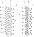
Figure 8 is a schematic enlarged detail of the closure formations indicated by the arrow VIII infigure 4 , -
Figure 9 is a schematic view showing the closure formations offigure 8 in the interlocked position, -
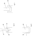
Figures 10-12 are schematic enlarged views showing different possible shapes of mutually interlockable projections and recesses of the closure formations, and -
Figure 13 is a perspective view of a reclosable pouch according to the present invention. - It should be appreciated that the attached drawings are schematic and not to scale with respect to real products. Various figures may not be represented in the same scale. Also, in various figures some elements may not be shown to better show other elements.
- With reference to
figure 1 numeral reference 10 indicates an apparatus for producing reclosable flexible pouches. - With reference to
figures 1 and 2 , theapparatus 10 comprises afeeding device 12 configured for feeding in a machine direction MD a continuousflexible sheet 14 having a longitudinal axis X extending along the machine direction MD. - The continuous
flexible sheet 14 may be unwound from a reel and may be printed with graphics. The continuousflexible sheet 14 is made of a material having heat-seal properties. The continuousflexible sheet 14 may have a multilayer structure comprising various plastic films, paper, air barrier layers, etc, as is common in packaging materials used for packaging food products. The continuousflexible sheet 14 may have at least one outer layer of thermoformable material. - The continuous
flexible sheet 14 may be made of a biodegradable and/or compostable material. The biodegradability of materials is defined according to the standard EN13432. In a possible embodiment the continuousflexible sheet 14 may be made of biodegradable and compostable bioplastic materials such as MATER-BI© or SPLASTICA. - In a possible embodiment the continuous
flexible sheet 14 may be made of a material recyclable with paper. The characteristics of the materials that can be recycled with paper may be defined by the standard Aticelca© 501/2017. The wording and icon "RECYCLABLE WITH PAPER - Aticelca© 501" on packages inform consumers about the recyclability with paper. The Aticelca® 501/2017 standard defines a test for recyclability of products (e.g. packaging material, printed material, articles for domestic use, etc.) made of more than 50% by weight of cellulosic materials. - With reference to
figure 2 , the continuousflexible sheet 14 has twolongitudinal side portions longitudinal side edges - With reference to
figures 1, 3 and7 , theapparatus 10 comprises a formingunit 23 configured for integrally forming in the twolongitudinal side portions flexible sheet 14 first and secondinterlockable closure formations longitudinal side edges - With reference to
figures 8 and 9 , each of the first and secondinterlockable closure formations projections 28 andrecesses 30 which are integrally formed on the surface of the twolongitudinal side portions flexible sheet 14 as the continuousflexible sheet 14 moves through the formingunit 23. - As shown in
figure 9 , theprojections 28 of thefirst closure formation 24 are configured for interlocking with therecesses 30 of thesecond closure formation 26 and theprojections 28 of thesecond closure formation 26 are configured for interlocking with therecesses 30 of thefirst closure formation 24. - In the configuration of
figure 3 in which the continuousflexible sheet 14 is flat at the exit of the formingunit 23 theprojections 30 of each of the first andsecond closure formations corresponding recesses 30 of theother closure formation recesses 30 of each of the first andsecond closure formations corresponding projections 28 of theother closure formation - The first and second
interlockable closure formations - With reference to
figure 7 , the formingunit 23 may comprise two ultrasonic formingdevices 32, each including ananvil 34 and a respectiveultrasonic horn 36. Theanvil 34 may be formed by a wheel rotating about an axis transverse to the machine direction MD. Theultrasonic horn 36 may include a vibrating rod cooperating with the outer surface of theanvil 34. In a possible embodiment, the ultrasonic horn may be formed by a vibrating roller rotating about an axis transverse to the machine direction MD. - The first and second
interlockable closure formations WO2010/085492 . This document discloses an apparatus and process for forming micro-hooks on a substrate for use as hook-type fasteners in touch fastening systems, wherein vibration energy is used to soften a substrate which is positioned between a mould and a source of vibration. The mould includes a plurality of cavities into which the softened substrate is forced to form the projections. The substrate may comprise a film, sheet, web, composite, laminate, etc. The source of vibration may be an ultrasonic horn. The process to form such micro-hooks may be operated in a continuous, semi-continuous or intermittent manner. - With reference to
figure 7 , eachanvil 34 has a plurality ofcavities 38 open on its outer cylindrical surface. Theultrasonic horns 36 compress the respectivelongitudinal side portions flexible sheet 14 against the outer cylindrical surfaces of therespective anvils 34 as the continuousflexible sheet 14 moves in the machine direction MD. - The vibrating energy produced by the
ultrasonic horns 36 liquifies or fluidifies locally the thermoformable material of the outer layer of the continuousflexible sheet 14, which penetrates in a fluid or liquid state in thecavities 38 of theanvils 34. The material of the continuousflexible sheet 14 which penetrates in the cavities of theanvils 34 cools in contact with the walls of thecavities 38 andforms projections 28 alternated torecesses 30 integral with the continuousflexible sheet 14. - As schematically shown in
figure 7 , at the exit of the formingunit 23 the continuousflexible sheet 14 has integrally formed first andsecond closure formations anvils 34 of the two ultrasonic formingdevices 32 are operated with a precise angular offset, such that theprojections 30 of thefirst closure formation 24 are transversally aligned to correspondingrecesses 30 of thesecond closure formation 26 and therecesses 30 of thefirst closure formation 24, are transversally aligned to correspondingprojections 28 of thesecond closure formation 26, and vice versa. - The first and
second closure formations closure formations anvil 34 an intermittent pattern ofcavities 38. Alternatively, eachanvil 34 may have a continuous pattern ofcavities 38 and theintermittent closure formations ultrasonic horns 36. As a further alternative, eachanvil 34 may have a continuous pattern ofcavities 38 and the intermittent first andsecond closure formations ultrasonic horns 36 from the outer cylindrical surfaces of therespective anvils 34. - In a possible embodiment, the forming
unit 23 may be a thermomechanical forming unit, in which the material of thelongitudinal side portions flexible sheet 14 is locally liquified or fluidified by heating and compression. - In order to form projections and cavities with dimensions sufficient for an effective interlocking, the continuous
flexible sheet 14 may be a monolayer sheet of thermoformable material or a multilayer sheet having an outer layer of thermoformable material, having a weight comprised between 10-300 g/m2. - The
cavities 38 of theanvil 34 may be shaped to formprojections 28 and recesses 30 with different shapes and dimensions.Figures 10-12 schematically show different possible shapes of theprojections 28 and recesses 30 of theclosure formations - In the embodiment of
figure 10 each of theprojections 28 has a roundedhead portion 40 connected to anarrower shank portion 42, and each of therecesses 30 has a V-shape with curved sides. - In the embodiment of
figure 11 each of theprojections 28 has a rectangular shape and each of therecesses 30 has a U-shape. - In the embodiment of
figure 12 therectangular projections 28 and theU-shaped recesses 30 have respective rounded corners. - With reference to
figures 1 and 4 , theapparatus 10 comprises afolding unit 44 configured for folding the continuousflexible sheet 14 about at least one foldingline 46 parallel to the longitudinal axis X. - In a possible embodiment, the
folding unit 44 may be configured for folding the continuousflexible sheet 14 about threefolding lines 46 parallel to the longitudinal axis X in a W-shaped configuration which opens to form a flat bottom. - After the longitudinal folding, the two
longitudinal side portions flexible sheet 14 are overlapped to each other so that the first andsecond closure formations - The folded continuous
flexible sheet 14 has a closed edge at the folding line(s) 46 and an open edge at the mutually facing side edges 20, 22. - With reference to
figures 1 and 5 , theapparatus 10 comprises a sealingunit 48 configured for joining to each other the twolongitudinal side portions flexible sheet 14 along sealinglines 50 extending between theclosed edge 46 and theopen edges flexible sheet 14. The sealingunit 48 may be a welding unit, for example an ultrasonic or thermocompression welding unit. - With reference to
figures 1 and 5 , theapparatus 10 comprises a cuttingunit 52 configured for cutting the continuous foldedflexible sheet 14 along cutting lines extending over thewelding lines 50, such that each cutting line is preceded and followed by a portion of arespective welding line 50. The cutting lines extend along the whole width of the said continuous foldedflexible sheet 14 so that downstream of the cutting unit 52 a continuous array of individualreclosable pouches 52 is formed. - The individual
reclosable pouches 52 are then filled. After filling, the mutually facing first andsecond closure formations reclosable pouches 52 are sealed between theedges closure formations -
Figure 13 schematically shows areclosable pouch 52 according to the present invention. - The reclosable
flexible pouch 52 comprises aflexible sheet 14 folded about at least one folding line 46 (preferably about three parallel folding lines 46) . - The
flexible sheet 14 has first and second mutually facingfront portions lines 50. The first and second mutually facingfront portions top edges interlockable closure formations top edges - The first and second
interlockable closure formations front portions - Each of the first and second
interlockable closure formations projections 28 and recesses 30 extending along a longitudinal direction X and configured for interlocking with therecesses 30 andprojections 28 of theother closure formation - The
projections 28 of each of the first and secondinterlockable closure formations recesses 30 of theother closure formation recesses 30 of each of the first and secondinterlockable closure formations projections 28 of theother closure formation - In a possible embodiment, the first and second
interlockable closure formations - The main advantages of the method according to the present invention are the following:
- low process temperatures,
- low power and energy required,
- high dimensional stability and precision of the reclosable closure formations,
- high manufacturing speeds,
- possibility of forming the closure formations in line with the formation of the pouches,
- possibility of customizing the shapes of the closure formations by appropriately forming the
anvils 34. - Of course, without prejudice to the principle of the invention, the details of construction and the embodiments can be varied, even significantly, with respect to those illustrated here without departing from the scope of the invention as defined by the following claims.
Claims (15)
- A reclosable flexible pouch (52), comprising a flexible sheet (14) folded about at least one folding line (46) and having first and second mutually facing front portions (16, 18) having respective side edges joined to each other along two sealing lines (50), the first and second mutually facing front portions (16, 18) having respective top edges (20, 22) and first and second interlockable closure formations (24, 26) adjacent to respective top edges (20, 22),
characterized in that said first and second interlockable closure formations (24, 26) are integrally formed with the respective mutually facing portions (16, 18), wherein each of said first and second interlockable closure formations (24, 26) has a succession of projections (28) and recesses (30) extending along a longitudinal direction (X) and configured for interlocking with the recesses (30) and projections (28) of the other closure formation (24, 26) . - The reclosable flexible pouch (52) of claim 1, wherein the projections (28) of each of said first and second interlockable closure formations (24, 26) are transversely aligned to corresponding recesses (30) of the other closure formation (24, 26) and the recesses (30) of each of said first and second interlockable closure formations (24, 26) are transversely aligned to corresponding projections (28) of the other closure formation (24, 26).
- The reclosable flexible pouch (52) of claim 1 or claim 2, wherein said first and second interlockable closure formations (24, 26) are equal to each other and offset with respect to each other along said longitudinal direction (X).
- The reclosable flexible pouch (52) of any of the preceding claims, wherein said flexible sheet (14) is made of a biodegradable and/or compostable material according to the standard EN13432.
- The reclosable flexible pouch (52) of any of the preceding claims, wherein said flexible sheet (14) is recyclable with paper according to the standard Aticelca© 501/2017.
- The reclosable flexible pouch (52) of any of the preceding claims, wherein said flexible sheet (14) is a monolayer sheet of thermoformable material or a multilayer sheet comprising at least one outer layer of thermoformable material.
- The reclosable flexible pouch (52) of claim 6, wherein said flexible sheet (14) has a weight comprised between 10-300 g/m2.
- A method for manufacturing reclosable flexible pouches (52), comprising:- feeding in a machine direction (MD) a continuous flexible sheet (14) having a longitudinal axis (X) extending along said machine direction (MD), two longitudinal side portions (16, 18) opposite to each other with respect to the longitudinal axis (X) and two opposite longitudinal side edges (20, 22),- integrally forming in said two longitudinal side portions (16, 18) first and second interlockable closure formations (24, 26) extending longitudinally adjacent to respective longitudinal side edges (20, 22), wherein each of said first and second interlockable closure formations (24, 26) has a succession of projections (28) and recesses (30) configured for interlocking with the recesses (30) and projections (28) of the other closure formation (24, 26),- folding said continuous flexible sheet (14) about at least one folding line (46) parallel to said longitudinal axis (X), and overlapping to each other said longitudinal side portions (16, 18) to form a continuous folded flexible sheet (14) having a closed edge (46) and an open edge (20, 22),- joining to each other the two overlapped longitudinal side portions (16, 18) along sealing lines (50), and- cutting said continuous folded flexible sheet (50) along cutting lines extending over said sealing lines (50) such that each cutting line is preceded and followed by a portion of a respective sealing line (50) .
- The method of claim 8, wherein the projections (28) of each of said first and second interlockable closure formations (24, 26) are transversely aligned to corresponding recesses (30) of the other closure formation (24, 26) and the recesses (30) of each of said first and second interlockable closure formations (24, 26) are transversely aligned to corresponding projections (28) of the other closure formation (24, 26),
- The method of claim 8 or claim 9, wherein said first and second interlockable closure formations (24, 26) are formed by locally liquifying or fluidifying thermoformable material on the surface of said continuous flexible sheet (14) and inserting the liquified or fluidified thermoformable material into cavities (38) of an anvil (34).
- The method of claim 10, wherein locally liquifying or fluidifying the thermoformable material is obtained by subjecting said continuous flexible sheet (14) to ultrasonic compression or to thermomechanical compression.
- The method of any of claims 8-11, wherein each of said first and second interlockable closure formations (24, 26) is formed intermittently in said machine direction (MD).
- An apparatus for manufacturing reclosable flexible pouches, comprising:- a feeding device (12) configured for feeding in a machine direction (MD) a continuous flexible sheet (14) having a longitudinal axis (X) extending along said machine direction (MD), two longitudinal side portions (16, 18) opposite to each other with respect to the longitudinal axis (X) and two opposite longitudinal side edges (20, 22),- a forming unit (23) configured for integrally forming in said two longitudinal side portions (16, 18) first and second interlockable closure formations (24, 26) extending longitudinally adjacent to respective longitudinal side edges (20, 22), wherein the forming unit (23) is configured for forming in each of said longitudinal side portions (16, 18) a succession of projections (28) and recesses (30) configured for interlocking with the recesses (30) and projections (28) of the other closure formation (24, 26),- a folding unit (44) configured for folding said continuous flexible sheet (14) about at least one folding line (46) parallel to said longitudinal axis (X), and for overlapping to each other said longitudinal side portions (16, 18) to form a continuous folded flexible sheet (14) having a closed edge (46) and an open edge (20, 22),- a sealing unit (48) configured for joining to each other the two overlapped longitudinal side portions (16, 18) along sealing lines (50), and- a cutting unit (52) configured for cutting said continuous folded flexible sheet (50) along cutting lines extending over said sealing lines (50) such that each cutting line is preceded and followed by a portion of a respective sealing line (50).
- The apparatus of claim 13, wherein said forming unit (23) comprises first and second ultrasonic forming devices (32) each including an anvil (34) having an outer surface provided with cavities (38) and an ultrasonic horn (36) cooperating with the outer surfaces of the respective anvil (34).
- The apparatus of claim 13 or claim 14, wherein the two anvils (34) of the two ultrasonic forming devices (32) are operated with an angular offset, such that the projections (30) of the first closure formation (24) are transversally aligned to corresponding recesses (30) of the second closure formation (26) and the recesses (30) of the first closure formation (24) are transversally aligned to corresponding projections (28) of the second closure formation (26), and vice versa.
Priority Applications (4)
| Application Number | Priority Date | Filing Date | Title |
|---|---|---|---|
| EP21213592.5A EP4194356A1 (en) | 2021-12-10 | 2021-12-10 | A reclosable flexible pouch and method and apparatus for manufacturing reclosable flexible pouches |
| US18/717,695 US20250042618A1 (en) | 2021-12-10 | 2022-11-14 | A reclosable flexible pouch and method and apparatus for manufacturing reclosable flexible pouches |
| EP22809217.7A EP4444623A1 (en) | 2021-12-10 | 2022-11-14 | A reclosable flexible pouch and method and apparatus for manufacturing reclosable flexible pouches |
| PCT/IB2022/060922 WO2023105321A1 (en) | 2021-12-10 | 2022-11-14 | A reclosable flexible pouch and method and apparatus for manufacturing reclosable flexible pouches |
Applications Claiming Priority (1)
| Application Number | Priority Date | Filing Date | Title |
|---|---|---|---|
| EP21213592.5A EP4194356A1 (en) | 2021-12-10 | 2021-12-10 | A reclosable flexible pouch and method and apparatus for manufacturing reclosable flexible pouches |
Publications (1)
| Publication Number | Publication Date |
|---|---|
| EP4194356A1 true EP4194356A1 (en) | 2023-06-14 |
Family
ID=78829358
Family Applications (2)
| Application Number | Title | Priority Date | Filing Date |
|---|---|---|---|
| EP21213592.5A Withdrawn EP4194356A1 (en) | 2021-12-10 | 2021-12-10 | A reclosable flexible pouch and method and apparatus for manufacturing reclosable flexible pouches |
| EP22809217.7A Pending EP4444623A1 (en) | 2021-12-10 | 2022-11-14 | A reclosable flexible pouch and method and apparatus for manufacturing reclosable flexible pouches |
Family Applications After (1)
| Application Number | Title | Priority Date | Filing Date |
|---|---|---|---|
| EP22809217.7A Pending EP4444623A1 (en) | 2021-12-10 | 2022-11-14 | A reclosable flexible pouch and method and apparatus for manufacturing reclosable flexible pouches |
Country Status (3)
| Country | Link |
|---|---|
| US (1) | US20250042618A1 (en) |
| EP (2) | EP4194356A1 (en) |
| WO (1) | WO2023105321A1 (en) |
Citations (7)
| Publication number | Priority date | Publication date | Assignee | Title |
|---|---|---|---|---|
| EP0023817A1 (en) * | 1979-08-06 | 1981-02-11 | Roeder Industrial Holdings Limited | Form-fill-seal apparatus and method of making reclosable bags |
| US4603434A (en) * | 1983-01-03 | 1986-07-29 | Mobil Oil Corporation | Ripple lock closure for flexible bags |
| EP0273327A2 (en) * | 1986-12-30 | 1988-07-06 | DowBrands Inc. | Method and apparatus for producing a reclosable bag film |
| EP0434447A1 (en) * | 1989-12-21 | 1991-06-26 | E.I. Du Pont De Nemours And Company | Assembling device to form a releasable bond between adjacent surface elements and method for manufacturing this assembling device |
| US20040066984A1 (en) * | 2002-10-04 | 2004-04-08 | Yi Li Jenny Jie | Built-in zipper bag and manufacturing method thereof |
| WO2010085492A1 (en) | 2009-01-20 | 2010-07-29 | Gerald Rocha | Method and apparatus for producing hook fasteners |
| US20210214129A1 (en) * | 2020-01-10 | 2021-07-15 | Progressive International Corporation | Flexible Container |
Family Cites Families (10)
| Publication number | Priority date | Publication date | Assignee | Title |
|---|---|---|---|---|
| US2035674A (en) * | 1933-02-11 | 1936-03-31 | Hookless Fastener Co | Fastening device |
| US4123826A (en) * | 1969-07-23 | 1978-11-07 | International Fastener Establishment | Separable fastener |
| US4812056A (en) * | 1985-03-25 | 1989-03-14 | The Dow Chemical Company | Reclosable, flexible container having an externally operated fastener |
| US5113555A (en) * | 1986-09-08 | 1992-05-19 | Minnesota Mining And Manufacturing Company | Container with intermeshable closure members |
| US5140727A (en) * | 1990-03-09 | 1992-08-25 | Dowbrands L.P. | Zipper for reclosable thermoplastic bag, process and apparatus for making |
| US5527112A (en) * | 1994-04-15 | 1996-06-18 | Dowbrands L.P. | Adhesive closure for flexible bag |
| US7850368B2 (en) * | 2004-06-04 | 2010-12-14 | S.C. Johnson & Son, Inc. | Closure device for a reclosable pouch |
| US7585111B2 (en) * | 2005-01-31 | 2009-09-08 | S.C. Johnson Home Storage, Inc. | Reclosable pouch and closure element therefor having interlocking closure profiles |
| US7340807B2 (en) * | 2005-01-31 | 2008-03-11 | S.C. Johnson Home Storage | Pouch and resealable closure mechanism therefor including a plurality of interlocking closure elements |
| US8622616B2 (en) * | 2010-06-03 | 2014-01-07 | Reynolds Presto Products, Inc. | Reclosable double zipper and methods |
-
2021
- 2021-12-10 EP EP21213592.5A patent/EP4194356A1/en not_active Withdrawn
-
2022
- 2022-11-14 EP EP22809217.7A patent/EP4444623A1/en active Pending
- 2022-11-14 WO PCT/IB2022/060922 patent/WO2023105321A1/en not_active Ceased
- 2022-11-14 US US18/717,695 patent/US20250042618A1/en active Pending
Patent Citations (7)
| Publication number | Priority date | Publication date | Assignee | Title |
|---|---|---|---|---|
| EP0023817A1 (en) * | 1979-08-06 | 1981-02-11 | Roeder Industrial Holdings Limited | Form-fill-seal apparatus and method of making reclosable bags |
| US4603434A (en) * | 1983-01-03 | 1986-07-29 | Mobil Oil Corporation | Ripple lock closure for flexible bags |
| EP0273327A2 (en) * | 1986-12-30 | 1988-07-06 | DowBrands Inc. | Method and apparatus for producing a reclosable bag film |
| EP0434447A1 (en) * | 1989-12-21 | 1991-06-26 | E.I. Du Pont De Nemours And Company | Assembling device to form a releasable bond between adjacent surface elements and method for manufacturing this assembling device |
| US20040066984A1 (en) * | 2002-10-04 | 2004-04-08 | Yi Li Jenny Jie | Built-in zipper bag and manufacturing method thereof |
| WO2010085492A1 (en) | 2009-01-20 | 2010-07-29 | Gerald Rocha | Method and apparatus for producing hook fasteners |
| US20210214129A1 (en) * | 2020-01-10 | 2021-07-15 | Progressive International Corporation | Flexible Container |
Also Published As
| Publication number | Publication date |
|---|---|
| US20250042618A1 (en) | 2025-02-06 |
| WO2023105321A1 (en) | 2023-06-15 |
| EP4444623A1 (en) | 2024-10-16 |
Similar Documents
| Publication | Publication Date | Title |
|---|---|---|
| AU2002305062B2 (en) | Gusseted packages | |
| US6986920B2 (en) | Composite web for making gusseted packages | |
| AU743250B2 (en) | Reinforced reclosable package seals | |
| EP0796802B1 (en) | Multiple film for bags | |
| JP5778681B2 (en) | Carton with resealable plastic header | |
| US20070230833A1 (en) | Reclosable Bag | |
| WO2015191504A1 (en) | Easy open and reclosable gusseted package with die-cut web and reclosure mechanism | |
| EP3344549B1 (en) | Method of forming a bonded tube for use as a package gusset | |
| WO2006062787A2 (en) | Easy opening rear seam bags and packaging methods | |
| US20220194018A1 (en) | Packages configured for improved sealing | |
| US20170233157A1 (en) | Film packaging and method of using same | |
| US20230382598A1 (en) | Fiber-based webs of closable bags | |
| US11731820B2 (en) | Packaging material and method for providing a packaging material | |
| US9475248B1 (en) | Method of manufacturing a flat bottom pouch | |
| US20120106877A1 (en) | Flexible packaging material and a package formed therewith | |
| US20180155084A1 (en) | Flat Patch Bottom Self Opening Style Bag and Method of Manufacture | |
| US20250042618A1 (en) | A reclosable flexible pouch and method and apparatus for manufacturing reclosable flexible pouches | |
| EP4194357A1 (en) | A zip strip for a flexible pouch and method and apparatus for manufacturing reclosable flexible pouches | |
| US20070181592A1 (en) | Dispenser package | |
| US3166457A (en) | Method of making bags | |
| SE521923C2 (en) | Packaging container and packaging material with a fastening strip against the inside | |
| US20180155086A1 (en) | Center Folded Bottom Self Opening Style Bag and Method of Manufacture | |
| JP4287252B2 (en) | Manufacturing method of package with chuck tape | |
| WO2019075170A1 (en) | Method of forming bottom-gusseted package with tape elements | |
| AU758157B2 (en) | Reinforced reclosable package seals |
Legal Events
| Date | Code | Title | Description |
|---|---|---|---|
| PUAI | Public reference made under article 153(3) epc to a published international application that has entered the european phase |
Free format text: ORIGINAL CODE: 0009012 |
|
| STAA | Information on the status of an ep patent application or granted ep patent |
Free format text: STATUS: THE APPLICATION HAS BEEN PUBLISHED |
|
| AK | Designated contracting states |
Kind code of ref document: A1 Designated state(s): AL AT BE BG CH CY CZ DE DK EE ES FI FR GB GR HR HU IE IS IT LI LT LU LV MC MK MT NL NO PL PT RO RS SE SI SK SM TR |
|
| STAA | Information on the status of an ep patent application or granted ep patent |
Free format text: STATUS: THE APPLICATION IS DEEMED TO BE WITHDRAWN |
|
| 18D | Application deemed to be withdrawn |
Effective date: 20231215 |