EP4194247A1 - Electric commercial vehicle comprising an impact device safety arrangement - Google Patents
Electric commercial vehicle comprising an impact device safety arrangement Download PDFInfo
- Publication number
- EP4194247A1 EP4194247A1 EP22211726.9A EP22211726A EP4194247A1 EP 4194247 A1 EP4194247 A1 EP 4194247A1 EP 22211726 A EP22211726 A EP 22211726A EP 4194247 A1 EP4194247 A1 EP 4194247A1
- Authority
- EP
- European Patent Office
- Prior art keywords
- electric power
- chassis
- unit
- impact device
- power module
- Prior art date
- Legal status (The legal status is an assumption and is not a legal conclusion. Google has not performed a legal analysis and makes no representation as to the accuracy of the status listed.)
- Pending
Links
Images



Classifications
-
- B—PERFORMING OPERATIONS; TRANSPORTING
- B60—VEHICLES IN GENERAL
- B60L—PROPULSION OF ELECTRICALLY-PROPELLED VEHICLES; SUPPLYING ELECTRIC POWER FOR AUXILIARY EQUIPMENT OF ELECTRICALLY-PROPELLED VEHICLES; ELECTRODYNAMIC BRAKE SYSTEMS FOR VEHICLES IN GENERAL; MAGNETIC SUSPENSION OR LEVITATION FOR VEHICLES; MONITORING OPERATING VARIABLES OF ELECTRICALLY-PROPELLED VEHICLES; ELECTRIC SAFETY DEVICES FOR ELECTRICALLY-PROPELLED VEHICLES
- B60L3/00—Electric devices on electrically-propelled vehicles for safety purposes; Monitoring operating variables, e.g. speed, deceleration or energy consumption
- B60L3/04—Cutting off the power supply under fault conditions
-
- B—PERFORMING OPERATIONS; TRANSPORTING
- B60—VEHICLES IN GENERAL
- B60L—PROPULSION OF ELECTRICALLY-PROPELLED VEHICLES; SUPPLYING ELECTRIC POWER FOR AUXILIARY EQUIPMENT OF ELECTRICALLY-PROPELLED VEHICLES; ELECTRODYNAMIC BRAKE SYSTEMS FOR VEHICLES IN GENERAL; MAGNETIC SUSPENSION OR LEVITATION FOR VEHICLES; MONITORING OPERATING VARIABLES OF ELECTRICALLY-PROPELLED VEHICLES; ELECTRIC SAFETY DEVICES FOR ELECTRICALLY-PROPELLED VEHICLES
- B60L3/00—Electric devices on electrically-propelled vehicles for safety purposes; Monitoring operating variables, e.g. speed, deceleration or energy consumption
- B60L3/0007—Measures or means for preventing or attenuating collisions
-
- B—PERFORMING OPERATIONS; TRANSPORTING
- B62—LAND VEHICLES FOR TRAVELLING OTHERWISE THAN ON RAILS
- B62D—MOTOR VEHICLES; TRAILERS
- B62D21/00—Understructures, i.e. chassis frame on which a vehicle body may be mounted
- B62D21/15—Understructures, i.e. chassis frame on which a vehicle body may be mounted having impact absorbing means, e.g. a frame designed to permanently or temporarily change shape or dimension upon impact with another body
-
- B—PERFORMING OPERATIONS; TRANSPORTING
- B62—LAND VEHICLES FOR TRAVELLING OTHERWISE THAN ON RAILS
- B62D—MOTOR VEHICLES; TRAILERS
- B62D33/00—Superstructures for load-carrying vehicles
- B62D33/06—Drivers' cabs
- B62D33/0604—Cabs insulated against vibrations or noise, e.g. with elastic suspension
-
- B—PERFORMING OPERATIONS; TRANSPORTING
- B60—VEHICLES IN GENERAL
- B60L—PROPULSION OF ELECTRICALLY-PROPELLED VEHICLES; SUPPLYING ELECTRIC POWER FOR AUXILIARY EQUIPMENT OF ELECTRICALLY-PROPELLED VEHICLES; ELECTRODYNAMIC BRAKE SYSTEMS FOR VEHICLES IN GENERAL; MAGNETIC SUSPENSION OR LEVITATION FOR VEHICLES; MONITORING OPERATING VARIABLES OF ELECTRICALLY-PROPELLED VEHICLES; ELECTRIC SAFETY DEVICES FOR ELECTRICALLY-PROPELLED VEHICLES
- B60L2200/00—Type of vehicles
- B60L2200/36—Vehicles designed to transport cargo, e.g. trucks
Definitions
- the invention relates to a commercial vehicle, comprising an impact device arranged for protecting a unit of the vehicle in case of a collision, by absorbing collision energy while switching off the high voltage system of the vehicle.
- Safety is a key development area for vehicles, such as trucks driven by an electric power source.
- One of the present targets defined by the EU is to have zero fatalities in road accidents in 2050.
- a general objective is to prevent hazardous situations, which may occur due to human or technical failures or due to lack of effective safety systems, e.g. after a collision.
- battery packs may be mounted to the chassis underneath the cabin, e.g. comparable to the position of a combustion engine installed in a conventionally powered vehicle.
- a number of electrical components, including high voltage (HV) wiring and connections, may be placed around these packs.
- HV high voltage
- the cabin may be moving rearward relative to the chassis, thereby impacting live HV components that are mounted in front of the battery pack.
- a damaged HV component may cause a hazardous situation, e.g. for the driver and passengers of the cabin or for first responders, due to a risk of electrocution.
- Known safety systems in battery electric vehicles may include passive measures, such as a safety cut loop which can be cut by rescue services, e.g. fire fighters, to switch off the high voltage system in case of an accident. During the period between the time of accident and the time of arrival of the rescue services, however, the safety of the driver and passengers may still be at risk.
- passive measures such as a safety cut loop which can be cut by rescue services, e.g. fire fighters, to switch off the high voltage system in case of an accident.
- rescue services e.g. fire fighters
- Other known safety systems may include active measures, such as crash sensors which can be used to trigger switching off the high voltage system based on a detected deceleration.
- Crash sensors may only act on deceleration levels above a certain threshold in a specific direction and may not be able to trigger a HV system switch-off when e.g. the deceleration levels are low or in case a collision is not exactly in line with the specific direction of the sensor.
- Increasing the sensitivity of the crash sensor may cause the HV system to switch off in unwanted situations, e.g. during emergency braking, which, in turn, creates a new hazardous situation.
- increasing the number of crash sensors to cover multiple directions may make the safety system more complex, and thereby prone to failure.
- aspects of the invention pertain to a commercial vehicle comprising an electric power module, a high voltage system, a control circuit, and an impact device.
- the electric power module is mounted to a chassis of the vehicle and arranged for providing electric power.
- the high voltage system is arranged for receiving electric power from the electric power module.
- the control circuit is coupled to the electric power module and arranged for providing a control signal.
- the control signal is arranged for switching the electric power module between an active state, in which electric power is provided to the high voltage system, and a passive safe state, in which electric power is switched off.
- the impact device forms a mechanical connection between the chassis and a unit of the vehicle, and is arranged for allowing a relative displacement between the unit and the chassis while maintaining the mechanical connection in case of a collision of the vehicle, to protect the unit by absorbing collision energy.
- the control circuit at least partially passes through the impact device.
- the impact device comprises an electrical conductor arranged for disconnecting by the relative movement between the chassis and the unit. When disconnected, the control circuit is interrupted, thereby switching the electric power module from the active state to the passive safe state.
- a simple and robust safety measure for protecting a driver or passenger of a commercial vehicle against high voltage (HV) hazards, in particular against risk of electric shock from damaged high voltage components can be provided in case of frontal impacts of the vehicle without the need for additional crash sensors which may not be able to detect all critical situations, such as low speed collisions.
- the presented safety measure can be triggered in all situations where the unit is moved relatively to the chassis, including situations in which the direction of the collision is at an angle to the driving direction of the vehicle, it may provide an effective measure that can reduce the risk of fire/explosion and contact with live HV parts, e.g. due to compression of HV components, by immediately switching off the HV system.
- the impact device is arranged for allowing a relative movement between the unit and the chassis, e.g. along a driving direction or lateral direction of the vehicle, between a normal condition and a shifted condition.
- the electrical conductor is arranged for disconnecting by a relative movement between the unit and the chassis from the normal condition to the shifted condition.
- the impact device absorbs collision energy by allowing the relative displacement between the unit, e.g. the cabin, and the chassis, while using the relative displacement to switch off the HV system of the commercial vehicle.
- the vehicle may be provided with more than one impact device, e.g. mounted at different positions and/or orientations between the unit and the chassis, to be able to detect collisions from different sides of the vehicle and/or with different angles of impact, and switch off the HV system accordingly.
- the impact device comprises a breaking element, wherein, prior to a collision, the breaking element is arranged for fixating the unit to the chassis in the normal condition, and wherein, in case of a collision, the breaking element is arranged for breaking to allow a relative movement between the unit and the chassis towards the shifted condition. Accordingly, collision energy can be absorbed by the impact device, while being able to interrupt the control circuit as soon as a collision force is detected, e.g. by having the breaking element form the electrical conductor, for example by being made of an electrically conductive material, to switch the electric power module from the active state to the passive safe state.
- the impact device can be arranged for interrupting the control circuit when the relative movement between the unit and the chassis exceeds a movement threshold, by disconnecting the electrical conductor.
- the control circuit is interrupted irreversibly, to prevent that the electric power module can unexpectedly be switched back from the passive safe state to the active state.
- the electrical conductor can be disconnected in a manner that separates the disconnected parts of the electrical conductor by a separation distance with a sufficient safety margin, e.g. a separation distance that cannot be bridged by accidental movements of the unit relative to the chassis, e.g. caused by the driver or passenger of the vehicle moving inside the cabin, or by rescue workers handling the vehicle.
- a sufficient safety margin e.g. a separation distance that cannot be bridged by accidental movements of the unit relative to the chassis, e.g. caused by the driver or passenger of the vehicle moving inside the cabin, or by rescue workers handling the vehicle.
- control circuit may comprise a one or more fuses, and the disconnected part corresponding to the supply side of the electrical conductor may be arranged to connect with the chassis, thereby creating a short circuit, and blow the one or more fuses.
- the movement threshold is measured from the normal condition.
- the movement threshold can for example be defined as a percentage of the total displacement possible between the normal condition and the shifted condition.
- the movement threshold can e.g. be smaller than 50% of the total possible displacement, such that the electric power module is switched to the passive safe state within the first halve of the maximum relative movement between the unit and the chassis. More preferably, the movement threshold is smaller than 25% of the total possible displacement, such that the electric power module is switched to the passive safe state within the first quarter of the maximum relative movement between the unit and the chassis.
- the unit is a cabin of the commercial vehicle.
- the impact device can protect the driver and passengers against impact by absorbing collision energy, by allowing the cabin to move relative to the chassis, while protecting the driver and passengers against electrocution by switching off the HV system of the vehicle.
- the impact device comprises at least one plate which is connected to the chassis, as well as a strip which in a lateral direction is positioned perpendicular to the at least one plate and with at least part of at least one of two longitudinal edges fixed to the at least one plate.
- a first end of the strip is connected to a connecting element that is connected to a transverse arm, and the transverse arm is connected to the cabin.
- the breaking element is mounted between the connecting element and the chassis, and the electrical conductor is arranged adjacent to the breaking element.
- the connecting element in case of a collision to absorb collision energy, is adapted to be distorted relative to the transverse arm by the breaking element being arranged to break first, thereby disconnecting the electrical conductor, prior to the strip being allowed to be torn loose from the at least one plate.
- the vehicle may comprise at least two impact devices, wherein the control circuit passes at least partially through each of the at least two impact devices in series.
- a redundant passive safety system can be provided, in which a disconnection of one of the electrical conductors of the at least two impact devices leads to switching the electric power module from the active state to the passive safe state, to switch of electric power to the high voltage system.
- the electrical conductor comprises a breakable electrical wire. Accordingly, the electrical conductor can be mounted adjacent to the breaking element and arranged for breaking when a tension force is applied on the electrical conductor, or when it is cut manually, e.g. by rescue services, to interrupt the control circuit.
- control circuit comprises a low power signal line arranged for providing the control signal, and wherein the electrical conductor is provided in the low power signal line.
- the electrical conductor can be arranged for disconnecting by the relative movement between the chassis and the unit, thereby providing fast and reliable switching of the electric power module from the active state to the passive safe state.
- the electric power module comprises one or more invertors, each provided with switchable elements, and the control signal is arranged for switching the electric power module to the active state by switching the switchable elements from a normally open position to a closed position. Accordingly, a disconnect of the electrical conductor, e.g. caused by a relative movement between the unit and the chassis, thereby interrupting the control circuit, can switch off the invertor.
- the electric power module comprises a power management system provided with contactors, and wherein the control signal is arranged for switching the electric power module to the active state by switching the contactors from a normally open position to a closed position.
- the power management system can be switched off when the control circuit is interrupted, e.g. by a disconnect of the electrical conductor caused by a relative movement between the unit and the chassis.
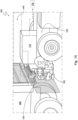
- FIGs 1A and 1B illustrate an embodiment of a commercial vehicle 100, such as a truck, e.g. a tractor-trailer combination or a box truck, a bus or other type of indoor or outdoor transport vehicle, a heavy duty vehicle, or agricultural vehicle.
- the commercial vehicle 100 comprises an electric power module 110, e.g. comprising a battery pack and a high voltage junction box.
- the vehicle further comprises a high voltage system 115 arranged for receiving electric power from the electric power module 110.
- the high voltage system 115 may comprise e.g. an electric motor for driving the vehicle, and/or other power electronics.
- the electric power module 110 is mounted to a chassis 120 of the vehicle 100 and is arranged for providing electric power to the high voltage system 115.
- the vehicle 100 further comprises an impact device 130, forming a mechanical connection between the chassis 120 and a unit 140 of the vehicle 100.
- the impact device 130 is arranged for allowing a relative movement DX between the unit 140 and the chassis 120 while maintaining the mechanical connection between the chassis 120 and the unit 140 in case of a collision of the vehicle 100, e.g. against the rear of a trailer of a preceding truck 200, to protect the unit 140 and/or or the electric power module 110 by absorbing collision energy.
- the unit 140 e.g. is the cabin of the vehicle 100
- the impact device 130 can protect the driver and passengers against impact by absorbing collision energy, by allowing the cabin to move relative to the chassis.
- the unit 140 can be the electric power module 110, or can be other components such as fuel cells, e.g. to reduce the forces acting on these modules or components during a collision, by allowing them to move relative to the chassis.
- the vehicle 100 further comprises a control circuit 150, as shown in FIG 5 , which is coupled to the electric power module 110 and arranged for providing a control signal, e.g. a signal arranged for controlling the power supply of components of the electric power module 110.
- the control circuit 150 at least partially passes through the impact device 130.
- the control signal may pass through a signal line, preferably a low power signal line, of the control circuit 150.
- the control signal can be arranged for switching the electric power module 110 between an active state, in which electric power is provided to the electric motor, and a passive safe state, in which electric power is switched off.
- the impact device 130 comprises an electrical conductor 135 arranged for disconnecting by the relative movement DX between the chassis 120 and the unit 140.
- the control circuit is interrupted, thereby switching the electric power module 110 from the active state to the passive safe state.
- the risk of electrical hazards e.g. due to a damaged high voltage system 115, can be mitigated for the cabin 140 including the driver and passengers of the vehicle 100.
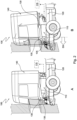
- FIGs 2A and 2B illustrate other or further embodiments of the vehicle 100.
- the impact device 130 is arranged for allowing a relative movement DX between the unit 140, e.g. the cabin of the vehicle 100, and the chassis 120, e.g. along a driving direction of the vehicle 100 or along a lateral direction of the vehicle 100, between a normal condition and a shifted condition.
- the unit 140 is a cabin of the vehicle 100, to protect the driver and passengers.
- the impact device 130 mechanically connects the unit 140 and the chassis 120 in a relative position and orientation in which the unit 140, e.g.
- the cabin, and the chassis 120 are aligned in a driving position.
- the unit 140 and the chassis 120 are shifted by the impact device 130 to a relative position and orientation in which the unit 140 and the chassis 120 are misaligned, e.g. displaced.
- the impact device 130 can e.g. allow a displacement between the normal condition and the shifted condition up to 40 centimeter, e.g between 20 and 40 centimeter, preferably between 30 and 40 centimeter, to absorb a sufficient amount of collision energy. Accordingly, the impact device 110 can provide an alternative solution to a crumple zone as used e.g. in passenger cars, by absorbing collision energy by allowing the relative displacement DX between the cabin 140 and the chassis 120.
- the present invention makes use of the relative displacement DX to switch the electric power module 110 from the active state to the passive safe state in which electric power to the high voltage system 115 is switched off, by having the impact device 130 comprise an electrical conductor 135 arranged for disconnecting by the relative movement DX between the chassis 120 and the unit 140.
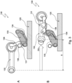
- FIGs 3A and 3B illustrate embodiments of the impact device 130.
- the impact device 130 comprises a breaking element 131.
- the breaking element 131 e.g. is an element of the impact device 130 that is arranged for breaking, e.g. breaking first, when a force exerted on the impact device 130 exceeds a predefined threshold, e.g. a breaking strength of the breaking element.
- a predefined threshold e.g. a breaking strength of the breaking element.
- the breaking element 131 can be regarded as a deliberately designed weakest link in the impact device 130.
- the breaking element 131 Prior to a collision, the breaking element 131 is arranged for fixating the unit to the chassis 120 in the normal condition, e.g. to prevent any relative movement between the unit and the chassis 120.
- the breaking element 131 can be mounted between a connecting element 136 and a plate 133.
- the plate 133 can e.g. be coupled to the chassis 120.
- the connecting element 136 can e.g. be coupled to the unit via a transverse arm 132.
- the impact device may further comprise a strip 134, which has a first end coupled to the connecting element 136 and a second end coupled to the plate 133 and has part of its longitudinal edge fixed to the plate 133, e.g. welded or brazed.
- the strip 134 and the plate 133 can be separated from each other along the fixated part of the longitudinal edge, to absorb collision energy.
- the mechanical strength of the plate 133 and the strip 134 can be higher than the mechanical strength of the fixated, e.g. welded, part of the longitudinal edge.
- the breaking element 135 may form the conducting element 135, as shown in FIG 3A , e.g. by being made of an electrically conducting material.
- the breaking element 131 is arranged for breaking, to allow a relative movement between the unit and the chassis towards the shifted condition.
- the breaking element 131 is broken, e.g. by a collision force, thereby allowing the relative movement DX between the plate 133 coupled to the chassis 120, and the transverse arm 132 coupled to the unit.
- the connecting element 136 is moved along with the transverse arm 132, thereby causing the connecting element 136 to be distorted and causing the strip 134 to be torn from the plate 133. Accordingly, collision energy can be absorbed by the impact device 130.
- the control circuit can be interrupted as soon as a relative displacement and/or a collision force applied on the impact device exceeds a threshold, e.g. a fracture strength or a breaking strength of the breaking element 131, to switch the electric power module from the active state to the passive safe state.
- a threshold e.g. a fracture strength or a breaking strength of the breaking element 131
- the distance S can be measured along the direction of the relative movement DX.
- the distance S between the normal condition, e.g. corresponding to the position of the transverse arm 132 relative to the chassis 120 as shown in FIG 3A and the shifted condition, e.g. corresponding to the position of the transverse arm 132 relative to the chassis 120 as shown in FIG 3B is up to 40 centimeter, e.g. in fully extended position of the impact device 130.
- the distance S between the normal condition and the shifted condition, e.g. in fully extended position of the impact device 130 is between 20 and 40 centimeter, or between 30 and 40 centimeter. In this way, the amount of collision energy that can be absorbed by the impact device 130 may be sufficient for protecting the unit, e.g. a cabin and its driver and passengers, against high impact collisions.
- the breaking element 131 is arranged for breaking to allow the relative movement DX when a collision force between the unit and the chassis 120 exceeds a threshold.
- the breaking element can be designed accordingly by comprising a material with a specific tensile strength, e.g. in combination with a minimum cross section area, to define a minimum breaking force for breaking the breaking element 131.
- a minimum breaking force may also be defined for the electrical conductor 135.
- the electrical conductor 135 may be arranged for disconnecting when a relative displacement between the transverse arm 132 and the chassis 120 exceeds a threshold, measured from the normal condition.
- the electrical conductor is arranged for disconnecting in the initial part of the distance S along the relative movement DX between the transverse arm 132 and the chassis 120, e.g. within the first 50% of the distance S, more preferably within the first 25% of the distance S.
- FIGs 4A and 4B illustrate other or further embodiments of the impact device 130.
- the impact device 130 comprises a plate 133 which is connected to the chassis 120, and a strip 134 which in a lateral direction is positioned perpendicular to the plate 133 and is fixed to the plate 133 with a part of at least one of its two longitudinal edges.
- the impact device 130 may comprise more than one plate 133, e.g. a pair of plates 133, such that the strip 134 is fixed with both longitudinal edges to the plates 133.
- the impact device 130 may comprise more than two plates 133, connected to more than one strip 134 in the manner described above.
- a first end of the strip 134 is connected to a connecting element 136 that is connected to a transverse arm 132.
- the transverse arm 132 can e.g. be connected to the cabin, or to another unit of the vehicle, such as the electric power module or a fuel cell.
- the breaking element 131 is mounted between the connecting element 136 and the chassis 120. As shown in FIGs 4A , the breaking element is coupled to the chassis 120 via the plate 133.
- the electrical conductor 135 is arranged adjacent to the breaking element 131.
- the electrical conductor 135 can for example be an electrical wire, optionally comprising a fuse or a connector, and arranged for breaking when a tension force is applied on the electrical conductor 135, to interrupt the control circuit.
- the electrical conductor may for instance comprise a breakable electrical wire.
- FIG 4B illustrates that, in case of a collision, the connecting element 136 is adapted to be distorted relative to the transverse arm 132 by the breaking element 131 being arranged to break first, thereby disconnecting the electrical conductor 135, prior to the strip 134 being allowed to be torn loose from the plate 133.
- an impact device 130 is provided that can absorb collision energy by converting relative movement DZ between the cabin and the chassis 120 into deformation of components of the impact device 130.
- the electrical conductor 135 being a separate entity from the breaking element 131, the electrical conductor 135 can e.g. be cut or manually interrupted to switch off the high voltage system of the vehicle, e.g. by rescue services, in case of a low impact collision in which the collision force is below the threshold, such that the breaking element 131 remains intact.
- FIGs 4A and 4B additionally illustrate several optional components of the impact device 130, for purposes of providing examples of further implementations of the impact device 130. These illustrated optional components may be obsolete in light of the basic functioning of the impact device described herein, or may be replaced by alternative solutions to provide similar effects.
- the connecting element 136 can be connected to the transverse arm 132 through a shaft 137 attached to the connecting element 136, to allow a rotation between the connection element 136 and the transverse arm 132 during the relative movement DX between the transverse arm 132 coupled to the cabin and the chassis 120.
- the first end of the strip 134 can be fixed to the shaft 137, e.g. through connection element 136 as illustrated in FIGs 4A and 4B .
- the strip 134 is torn from the plate 133 by a movement combining a translation and a rotation, thereby optimizing the amount of collision energy that can be absorbed by the impact device 130.
- the shaft 137 can be located in a central position in an eyelet 138 fixed to an end of the transverse arm 132, which eyelet has an inner diameter exceeding a diameter of the shaft 137.
- the connecting element 136 can be constrained with respect to the transverse arm, to maintain the mechanical connection between the cabin and the chassis 120, e.g. by a bearing.
- a flexible element 139 may optionally be present between the eyelet 138 and the shaft 137. Accordingly, in case of a collision when the connecting element 136 is distorted relative to the transverse arm 132, additional collision energy can be absorbed by the flexible element 139 being deformed, e.g. as shown in FIG 4B .
- FIG 5 provides a diagram of an embodiment of a control circuit 150 of the vehicle.
- the control circuit is for example coupled to a low voltage (e.g. 24V) circuit of the electric power module 110, which may further comprise a main switch 115, one or more high voltage relay boxes 111, a battery/power management system 112, and one or more invertors 113.
- a low voltage (e.g. 24V) circuit of the electric power module 110 which may further comprise a main switch 115, one or more high voltage relay boxes 111, a battery/power management system 112, and one or more invertors 113.
- the control circuit 150 may comprise a low power signal line 151 arranged for providing the control signal, e.g. a signal arranged for controlling an input of one or more of the components of the electric power module 110.
- the control signal can e.g. be a continuous signal.
- the low power signal line 151 e.g. passes through the impact device 130, and the control signal is arranged for switching the electric power module 110 between the active state and the passive safe state, e.g. by switching one or more invertors 113 and/or the power management system 112 between a condition in which they receive power, and a condition in which they cannot receive power.
- the electrical conductor 135, arranged for interrupting the control circuit 150, is provided in the low power signal line 151.
- the electrical conductor 135 is arranged for disconnecting by the relative movement between the chassis and the unit, thereby switching the electric power module 110 from the active state to the passive safe state.
- the control signal can be used for controlling a normally open switchable element in the one or more invertors 113 and/or in the power management system 112 to switch to a closed position, to switch the one or more invertors 113 and/or in the power management system 112 to the active state.
- the control signal is lost, or interrupted, the one or more invertors 113 and/or in the power management system 112 are switched back to the passive safe state by default, in which their power supply is shut off.
- the power management system 112 and the one or more invertors 113 can for example be arranged to not go back to the active state in case the electrical conductor 135 would unexpectedly get closed again.
- a key cycle from main switch 115 may e.g. be needed to reset the power management system 112 and the one or more invertors 113 such that they allow the active state again.
- the low power signal line 151 can e.g. be provided with one or more fuses 139.
- the breaking element interrupts the electrical conductor 135, the broken parts of the breaking element may for example create a short circuit, e.g. by connecting the supply side of the electrical conductor 135 to the vehicle chassis, thereby blowing the one or more fuses 139 and ensuring that the electric power module 110 remains in the passive safe state.
- the electric power module 110 comprises an invertor 113 provided with switchable elements, e.g. arranged for supplying power to the invertor 113.
- the switchable elements are configured to be in a normally open position.
- the control signal is arranged for switching the electric power module 110 to the active state by switching the switchable elements from the normally open position to a closed position, e.g. in which the invertor 113 is supplied with power.
- the switchable elements may be switched to the normally open position by default, thereby switching off the power supply of the invertor 113, and switching off the HV system of the vehicle accordingly.
- the electric power module 110 may further comprise a power management system 112 provided with contactors, e.g. arranged for supplying power to the power management system 112.
- the contactors can be configured to be in a normally open position.
- the control signal is arranged for switching the electric power module 110 to the active state by switching the contactors from the normally open position to a closed position, e.g. in which the power management system 112 receives power.
- the contactors may be switched to the normally open position by default when the control circuit 150 is interrupted, e.g. by the electrical conductor 135 disconnecting caused by a relative movement of the impact device described herein, so that the power supply of the power management system 112 is switched off, thereby switching off the HV system of the vehicle.
- control signal can be arranged for switching other components of the electric power module 110 and/or the vehicle 100 between an active state and a passive safe state, e.g. in which power supply is shut off by default.
- control circuit can be arranged for providing a redundant safety system for switching off the HV system of a commercial vehicle, e.g. driven or powered by an electric power source.
Landscapes
- Engineering & Computer Science (AREA)
- Transportation (AREA)
- Mechanical Engineering (AREA)
- Life Sciences & Earth Sciences (AREA)
- Sustainable Development (AREA)
- Sustainable Energy (AREA)
- Power Engineering (AREA)
- Chemical & Material Sciences (AREA)
- Combustion & Propulsion (AREA)
- Electric Propulsion And Braking For Vehicles (AREA)
Abstract
Description
- The invention relates to a commercial vehicle, comprising an impact device arranged for protecting a unit of the vehicle in case of a collision, by absorbing collision energy while switching off the high voltage system of the vehicle.
- Safety is a key development area for vehicles, such as trucks driven by an electric power source. One of the present targets defined by the EU is to have zero fatalities in road accidents in 2050. As such, a general objective is to prevent hazardous situations, which may occur due to human or technical failures or due to lack of effective safety systems, e.g. after a collision.
- For example in battery powered commercial vehicles, battery packs may be mounted to the chassis underneath the cabin, e.g. comparable to the position of a combustion engine installed in a conventionally powered vehicle. A number of electrical components, including high voltage (HV) wiring and connections, may be placed around these packs. For example, in case of a frontal collision of a truck against a trailer of a preceding truck, the cabin may be moving rearward relative to the chassis, thereby impacting live HV components that are mounted in front of the battery pack. A damaged HV component may cause a hazardous situation, e.g. for the driver and passengers of the cabin or for first responders, due to a risk of electrocution.
- Known safety systems in battery electric vehicles may include passive measures, such as a safety cut loop which can be cut by rescue services, e.g. fire fighters, to switch off the high voltage system in case of an accident. During the period between the time of accident and the time of arrival of the rescue services, however, the safety of the driver and passengers may still be at risk.
- Other known safety systems may include active measures, such as crash sensors which can be used to trigger switching off the high voltage system based on a detected deceleration. Crash sensors, however, may only act on deceleration levels above a certain threshold in a specific direction and may not be able to trigger a HV system switch-off when e.g. the deceleration levels are low or in case a collision is not exactly in line with the specific direction of the sensor. Increasing the sensitivity of the crash sensor may cause the HV system to switch off in unwanted situations, e.g. during emergency braking, which, in turn, creates a new hazardous situation. Similarly, increasing the number of crash sensors to cover multiple directions may make the safety system more complex, and thereby prone to failure.
- It is an object of the present invention to provide a safety system for a commercial vehicle , wherein the safety system is able to protect the driver and passengers against high voltage hazards in case of a collision, while being robust and simple.
- In summary, aspects of the invention pertain to a commercial vehicle comprising an electric power module, a high voltage system, a control circuit, and an impact device. The electric power module is mounted to a chassis of the vehicle and arranged for providing electric power. The high voltage system is arranged for receiving electric power from the electric power module. The control circuit is coupled to the electric power module and arranged for providing a control signal. The control signal is arranged for switching the electric power module between an active state, in which electric power is provided to the high voltage system, and a passive safe state, in which electric power is switched off. The impact device forms a mechanical connection between the chassis and a unit of the vehicle, and is arranged for allowing a relative displacement between the unit and the chassis while maintaining the mechanical connection in case of a collision of the vehicle, to protect the unit by absorbing collision energy. The control circuit at least partially passes through the impact device. The impact device comprises an electrical conductor arranged for disconnecting by the relative movement between the chassis and the unit. When disconnected, the control circuit is interrupted, thereby switching the electric power module from the active state to the passive safe state.
- Accordingly, a simple and robust safety measure for protecting a driver or passenger of a commercial vehicle against high voltage (HV) hazards, in particular against risk of electric shock from damaged high voltage components, can be provided in case of frontal impacts of the vehicle without the need for additional crash sensors which may not be able to detect all critical situations, such as low speed collisions. Since the presented safety measure can be triggered in all situations where the unit is moved relatively to the chassis, including situations in which the direction of the collision is at an angle to the driving direction of the vehicle, it may provide an effective measure that can reduce the risk of fire/explosion and contact with live HV parts, e.g. due to compression of HV components, by immediately switching off the HV system.
- In case of a collision, the impact device is arranged for allowing a relative movement between the unit and the chassis, e.g. along a driving direction or lateral direction of the vehicle, between a normal condition and a shifted condition. Preferably, the electrical conductor is arranged for disconnecting by a relative movement between the unit and the chassis from the normal condition to the shifted condition. Accordingly, the impact device absorbs collision energy by allowing the relative displacement between the unit, e.g. the cabin, and the chassis, while using the relative displacement to switch off the HV system of the commercial vehicle. The vehicle may be provided with more than one impact device, e.g. mounted at different positions and/or orientations between the unit and the chassis, to be able to detect collisions from different sides of the vehicle and/or with different angles of impact, and switch off the HV system accordingly.
- In other or further embodiments, the impact device comprises a breaking element, wherein, prior to a collision, the breaking element is arranged for fixating the unit to the chassis in the normal condition, and wherein, in case of a collision, the breaking element is arranged for breaking to allow a relative movement between the unit and the chassis towards the shifted condition. Accordingly, collision energy can be absorbed by the impact device, while being able to interrupt the control circuit as soon as a collision force is detected, e.g. by having the breaking element form the electrical conductor, for example by being made of an electrically conductive material, to switch the electric power module from the active state to the passive safe state.
- To be able to distinguish between acceleration forces under normal driving conditions of the vehicle, during which the unit and the chassis should remain fixed to each other, and collision forces, during which the unit and the chassis should move relative to each other, the impact device can be arranged for interrupting the control circuit when the relative movement between the unit and the chassis exceeds a movement threshold, by disconnecting the electrical conductor. Preferably, the control circuit is interrupted irreversibly, to prevent that the electric power module can unexpectedly be switched back from the passive safe state to the active state.
- For example, the electrical conductor can be disconnected in a manner that separates the disconnected parts of the electrical conductor by a separation distance with a sufficient safety margin, e.g. a separation distance that cannot be bridged by accidental movements of the unit relative to the chassis, e.g. caused by the driver or passenger of the vehicle moving inside the cabin, or by rescue workers handling the vehicle.
- Alternatively, or additionally, the control circuit may comprise a one or more fuses, and the disconnected part corresponding to the supply side of the electrical conductor may be arranged to connect with the chassis, thereby creating a short circuit, and blow the one or more fuses.
- Preferably, the movement threshold is measured from the normal condition. The movement threshold can for example be defined as a percentage of the total displacement possible between the normal condition and the shifted condition. The movement threshold can e.g. be smaller than 50% of the total possible displacement, such that the electric power module is switched to the passive safe state within the first halve of the maximum relative movement between the unit and the chassis. More preferably, the movement threshold is smaller than 25% of the total possible displacement, such that the electric power module is switched to the passive safe state within the first quarter of the maximum relative movement between the unit and the chassis.
- In some embodiments, the unit is a cabin of the commercial vehicle. As such, the impact device can protect the driver and passengers against impact by absorbing collision energy, by allowing the cabin to move relative to the chassis, while protecting the driver and passengers against electrocution by switching off the HV system of the vehicle.
- In other or further embodiments, the impact device comprises at least one plate which is connected to the chassis, as well as a strip which in a lateral direction is positioned perpendicular to the at least one plate and with at least part of at least one of two longitudinal edges fixed to the at least one plate. A first end of the strip is connected to a connecting element that is connected to a transverse arm, and the transverse arm is connected to the cabin. The breaking element is mounted between the connecting element and the chassis, and the electrical conductor is arranged adjacent to the breaking element. The connecting element, in case of a collision to absorb collision energy, is adapted to be distorted relative to the transverse arm by the breaking element being arranged to break first, thereby disconnecting the electrical conductor, prior to the strip being allowed to be torn loose from the at least one plate.
- To further protect the driver and/or passengers of the commercial vehicle against high voltage hazards, the vehicle may comprise at least two impact devices, wherein the control circuit passes at least partially through each of the at least two impact devices in series. In this way, a redundant passive safety system can be provided, in which a disconnection of one of the electrical conductors of the at least two impact devices leads to switching the electric power module from the active state to the passive safe state, to switch of electric power to the high voltage system.
- In some embodiments, the electrical conductor comprises a breakable electrical wire. Accordingly, the electrical conductor can be mounted adjacent to the breaking element and arranged for breaking when a tension force is applied on the electrical conductor, or when it is cut manually, e.g. by rescue services, to interrupt the control circuit.
- In other or further embodiments, the control circuit comprises a low power signal line arranged for providing the control signal, and wherein the electrical conductor is provided in the low power signal line. By having the electrical conductor in the low power signal line passing through the impact device, the electrical conductor can be arranged for disconnecting by the relative movement between the chassis and the unit, thereby providing fast and reliable switching of the electric power module from the active state to the passive safe state.
- In some embodiments, the electric power module comprises one or more invertors, each provided with switchable elements, and the control signal is arranged for switching the electric power module to the active state by switching the switchable elements from a normally open position to a closed position. Accordingly, a disconnect of the electrical conductor, e.g. caused by a relative movement between the unit and the chassis, thereby interrupting the control circuit, can switch off the invertor.
- In other or further embodiments, the electric power module comprises a power management system provided with contactors, and wherein the control signal is arranged for switching the electric power module to the active state by switching the contactors from a normally open position to a closed position. As such, the power management system can be switched off when the control circuit is interrupted, e.g. by a disconnect of the electrical conductor caused by a relative movement between the unit and the chassis.
- The invention will be further elucidated in the figures:
-
FIGs 1A and1B illustrate an embodiment of a commercial vehicle comprising an impact device; -
FIGs 2A and 2B illustrate other or further embodiments of the commercial vehicle; -
FIGs 3A and 3B illustrate embodiments of the impact device; -
FIGs 4A and 4B illustrate other or further embodiments of the impact device; -
FIG 5 provides a diagram of an embodiment of a control circuit of the commercial vehicle. - The invention is described more fully hereinafter with reference to the accompanying drawings, in which embodiments of the invention are shown. In the drawings, the absolute and relative sizes of systems, components, layers, and regions may be exaggerated for clarity. Embodiments may be described with reference to schematic and/or cross-section illustrations of possibly idealized embodiments and intermediate structures of the invention. In the description and drawings, like numbers refer to like elements throughout. Relative terms as well as derivatives thereof should be construed to refer to the orientation as then described or as shown in the drawing under discussion. These relative terms are for convenience of description and do not require that the system be constructed or operated in a particular orientation unless stated otherwise.
-
FIGs 1A and1B illustrate an embodiment of acommercial vehicle 100, such as a truck, e.g. a tractor-trailer combination or a box truck, a bus or other type of indoor or outdoor transport vehicle, a heavy duty vehicle, or agricultural vehicle. Thecommercial vehicle 100 comprises anelectric power module 110, e.g. comprising a battery pack and a high voltage junction box. The vehicle further comprises ahigh voltage system 115 arranged for receiving electric power from theelectric power module 110. Thehigh voltage system 115 may comprise e.g. an electric motor for driving the vehicle, and/or other power electronics. Theelectric power module 110 is mounted to achassis 120 of thevehicle 100 and is arranged for providing electric power to thehigh voltage system 115. - The
vehicle 100 further comprises animpact device 130, forming a mechanical connection between thechassis 120 and aunit 140 of thevehicle 100. Theimpact device 130 is arranged for allowing a relative movement DX between theunit 140 and thechassis 120 while maintaining the mechanical connection between thechassis 120 and theunit 140 in case of a collision of thevehicle 100, e.g. against the rear of a trailer of a precedingtruck 200, to protect theunit 140 and/or or theelectric power module 110 by absorbing collision energy. For example, when theunit 140 e.g. is the cabin of thevehicle 100, theimpact device 130 can protect the driver and passengers against impact by absorbing collision energy, by allowing the cabin to move relative to the chassis. Alternatively, or additionally, theunit 140 can be theelectric power module 110, or can be other components such as fuel cells, e.g. to reduce the forces acting on these modules or components during a collision, by allowing them to move relative to the chassis. - The
vehicle 100 further comprises acontrol circuit 150, as shown inFIG 5 , which is coupled to theelectric power module 110 and arranged for providing a control signal, e.g. a signal arranged for controlling the power supply of components of theelectric power module 110. Thecontrol circuit 150 at least partially passes through theimpact device 130. For example, the control signal may pass through a signal line, preferably a low power signal line, of thecontrol circuit 150. For example by having signal line mounted to the impact device, it can be broken by the relative movement between the unit and the chassis, thereby interrupting the control signal. As such, the control signal can be arranged for switching theelectric power module 110 between an active state, in which electric power is provided to the electric motor, and a passive safe state, in which electric power is switched off. - Back to
FIG 1 , theimpact device 130 comprises anelectrical conductor 135 arranged for disconnecting by the relative movement DX between thechassis 120 and theunit 140. When disconnected, the control circuit is interrupted, thereby switching theelectric power module 110 from the active state to the passive safe state. In this way, during a collision of thevehicle 100, e.g. against the rear of a precedingtruck 200, the risk of electrical hazards, e.g. due to a damagedhigh voltage system 115, can be mitigated for thecabin 140 including the driver and passengers of thevehicle 100. -
FIGs 2A and 2B illustrate other or further embodiments of thevehicle 100. In case of a collision, as shown inFIG 2B , theimpact device 130 is arranged for allowing a relative movement DX between theunit 140, e.g. the cabin of thevehicle 100, and thechassis 120, e.g. along a driving direction of thevehicle 100 or along a lateral direction of thevehicle 100, between a normal condition and a shifted condition. Preferably, theunit 140 is a cabin of thevehicle 100, to protect the driver and passengers. For example in the normal condition, e.g. prior to a collision as shown inFIG 2A , theimpact device 130 mechanically connects theunit 140 and thechassis 120 in a relative position and orientation in which theunit 140, e.g. the cabin, and thechassis 120 are aligned in a driving position. For example in the shifted condition, e.g. after a collision as shown inFIG 2B , theunit 140 and thechassis 120 are shifted by theimpact device 130 to a relative position and orientation in which theunit 140 and thechassis 120 are misaligned, e.g. displaced. - The
impact device 130 can e.g. allow a displacement between the normal condition and the shifted condition up to 40 centimeter, e.g between 20 and 40 centimeter, preferably between 30 and 40 centimeter, to absorb a sufficient amount of collision energy. Accordingly, theimpact device 110 can provide an alternative solution to a crumple zone as used e.g. in passenger cars, by absorbing collision energy by allowing the relative displacement DX between thecabin 140 and thechassis 120. The present invention makes use of the relative displacement DX to switch theelectric power module 110 from the active state to the passive safe state in which electric power to thehigh voltage system 115 is switched off, by having theimpact device 130 comprise anelectrical conductor 135 arranged for disconnecting by the relative movement DX between thechassis 120 and theunit 140. -
FIGs 3A and 3B illustrate embodiments of theimpact device 130. Theimpact device 130 comprises abreaking element 131. The breakingelement 131 e.g. is an element of theimpact device 130 that is arranged for breaking, e.g. breaking first, when a force exerted on theimpact device 130 exceeds a predefined threshold, e.g. a breaking strength of the breaking element. As such, the breakingelement 131 can be regarded as a deliberately designed weakest link in theimpact device 130. - Prior to a collision, the breaking
element 131 is arranged for fixating the unit to thechassis 120 in the normal condition, e.g. to prevent any relative movement between the unit and thechassis 120. For example as shown inFIG 3A , the breakingelement 131 can be mounted between a connectingelement 136 and aplate 133. Theplate 133 can e.g. be coupled to thechassis 120. The connectingelement 136 can e.g. be coupled to the unit via atransverse arm 132. The impact device may further comprise astrip 134, which has a first end coupled to the connectingelement 136 and a second end coupled to theplate 133 and has part of its longitudinal edge fixed to theplate 133, e.g. welded or brazed. Thestrip 134 and theplate 133 can be separated from each other along the fixated part of the longitudinal edge, to absorb collision energy. For example, in the direction of the relative movement DX, the mechanical strength of theplate 133 and thestrip 134 can be higher than the mechanical strength of the fixated, e.g. welded, part of the longitudinal edge. The breakingelement 135 may form the conductingelement 135, as shown inFIG 3A , e.g. by being made of an electrically conducting material. - In case of a collision, the breaking
element 131 is arranged for breaking, to allow a relative movement between the unit and the chassis towards the shifted condition. For example as shown inFIG 3B , the breakingelement 131 is broken, e.g. by a collision force, thereby allowing the relative movement DX between theplate 133 coupled to thechassis 120, and thetransverse arm 132 coupled to the unit. As a result of the relative movement DX being allowed by thebroken breaking element 131, the connectingelement 136 is moved along with thetransverse arm 132, thereby causing the connectingelement 136 to be distorted and causing thestrip 134 to be torn from theplate 133. Accordingly, collision energy can be absorbed by theimpact device 130. By having the breakingelement 131 form the conductingelement 135, the control circuit can be interrupted as soon as a relative displacement and/or a collision force applied on the impact device exceeds a threshold, e.g. a fracture strength or a breaking strength of the breakingelement 131, to switch the electric power module from the active state to the passive safe state. - The distance S can be measured along the direction of the relative movement DX. Preferably, the distance S between the normal condition, e.g. corresponding to the position of the
transverse arm 132 relative to thechassis 120 as shown inFIG 3A and the shifted condition, e.g. corresponding to the position of thetransverse arm 132 relative to thechassis 120 as shown inFIG 3B , is up to 40 centimeter, e.g. in fully extended position of theimpact device 130. For example, the distance S between the normal condition and the shifted condition, e.g. in fully extended position of theimpact device 130, is between 20 and 40 centimeter, or between 30 and 40 centimeter. In this way, the amount of collision energy that can be absorbed by theimpact device 130 may be sufficient for protecting the unit, e.g. a cabin and its driver and passengers, against high impact collisions. - In other or further preferred embodiments, the breaking
element 131 is arranged for breaking to allow the relative movement DX when a collision force between the unit and thechassis 120 exceeds a threshold. For example, the breaking element can be designed accordingly by comprising a material with a specific tensile strength, e.g. in combination with a minimum cross section area, to define a minimum breaking force for breaking thebreaking element 131. Such a minimum breaking force may also be defined for theelectrical conductor 135. Alternatively, or additionally, theelectrical conductor 135 may be arranged for disconnecting when a relative displacement between thetransverse arm 132 and thechassis 120 exceeds a threshold, measured from the normal condition. Preferably, the electrical conductor is arranged for disconnecting in the initial part of the distance S along the relative movement DX between thetransverse arm 132 and thechassis 120, e.g. within the first 50% of the distance S, more preferably within the first 25% of the distance S. -
FIGs 4A and 4B illustrate other or further embodiments of theimpact device 130. Theimpact device 130 comprises aplate 133 which is connected to thechassis 120, and astrip 134 which in a lateral direction is positioned perpendicular to theplate 133 and is fixed to theplate 133 with a part of at least one of its two longitudinal edges. Theimpact device 130 may comprise more than oneplate 133, e.g. a pair ofplates 133, such that thestrip 134 is fixed with both longitudinal edges to theplates 133. Alternatively, theimpact device 130 may comprise more than twoplates 133, connected to more than onestrip 134 in the manner described above. - A first end of the
strip 134 is connected to a connectingelement 136 that is connected to atransverse arm 132. Thetransverse arm 132 can e.g. be connected to the cabin, or to another unit of the vehicle, such as the electric power module or a fuel cell. - The breaking
element 131 is mounted between the connectingelement 136 and thechassis 120. As shown inFIGs 4A , the breaking element is coupled to thechassis 120 via theplate 133. Theelectrical conductor 135 is arranged adjacent to thebreaking element 131. Theelectrical conductor 135 can for example be an electrical wire, optionally comprising a fuse or a connector, and arranged for breaking when a tension force is applied on theelectrical conductor 135, to interrupt the control circuit. The electrical conductor may for instance comprise a breakable electrical wire. -
FIG 4B illustrates that, in case of a collision, the connectingelement 136 is adapted to be distorted relative to thetransverse arm 132 by the breakingelement 131 being arranged to break first, thereby disconnecting theelectrical conductor 135, prior to thestrip 134 being allowed to be torn loose from theplate 133. Accordingly, animpact device 130 is provided that can absorb collision energy by converting relative movement DZ between the cabin and thechassis 120 into deformation of components of theimpact device 130. By theelectrical conductor 135 being a separate entity from the breakingelement 131, theelectrical conductor 135 can e.g. be cut or manually interrupted to switch off the high voltage system of the vehicle, e.g. by rescue services, in case of a low impact collision in which the collision force is below the threshold, such that the breakingelement 131 remains intact. - Though not contributing to the present invention as such,
FIGs 4A and 4B additionally illustrate several optional components of theimpact device 130, for purposes of providing examples of further implementations of theimpact device 130. These illustrated optional components may be obsolete in light of the basic functioning of the impact device described herein, or may be replaced by alternative solutions to provide similar effects. - For example, the connecting
element 136 can be connected to thetransverse arm 132 through ashaft 137 attached to the connectingelement 136, to allow a rotation between theconnection element 136 and thetransverse arm 132 during the relative movement DX between thetransverse arm 132 coupled to the cabin and thechassis 120. - Optionally, the first end of the
strip 134 can be fixed to theshaft 137, e.g. throughconnection element 136 as illustrated inFIGs 4A and 4B . In this way, during the relative movement DX, thestrip 134 is torn from theplate 133 by a movement combining a translation and a rotation, thereby optimizing the amount of collision energy that can be absorbed by theimpact device 130. - As a further example shown in
FIGs 4A and 4B , theshaft 137 can be located in a central position in aneyelet 138 fixed to an end of thetransverse arm 132, which eyelet has an inner diameter exceeding a diameter of theshaft 137. As such, during the relative rotation, the connectingelement 136 can be constrained with respect to the transverse arm, to maintain the mechanical connection between the cabin and thechassis 120, e.g. by a bearing. - Additionally, a
flexible element 139 may optionally be present between theeyelet 138 and theshaft 137. Accordingly, in case of a collision when the connectingelement 136 is distorted relative to thetransverse arm 132, additional collision energy can be absorbed by theflexible element 139 being deformed, e.g. as shown inFIG 4B . -
FIG 5 provides a diagram of an embodiment of acontrol circuit 150 of the vehicle. The control circuit is for example coupled to a low voltage (e.g. 24V) circuit of theelectric power module 110, which may further comprise amain switch 115, one or more highvoltage relay boxes 111, a battery/power management system 112, and one ormore invertors 113. - The
control circuit 150 may comprise a lowpower signal line 151 arranged for providing the control signal, e.g. a signal arranged for controlling an input of one or more of the components of theelectric power module 110. The control signal can e.g. be a continuous signal. The lowpower signal line 151 e.g. passes through theimpact device 130, and the control signal is arranged for switching theelectric power module 110 between the active state and the passive safe state, e.g. by switching one ormore invertors 113 and/or thepower management system 112 between a condition in which they receive power, and a condition in which they cannot receive power. - The
electrical conductor 135, arranged for interrupting thecontrol circuit 150, is provided in the lowpower signal line 151. By having theelectrical conductor 135 in the lowpower signal line 151 passing through the impact device, theelectrical conductor 135 is arranged for disconnecting by the relative movement between the chassis and the unit, thereby switching theelectric power module 110 from the active state to the passive safe state. For example, the control signal can be used for controlling a normally open switchable element in the one ormore invertors 113 and/or in thepower management system 112 to switch to a closed position, to switch the one ormore invertors 113 and/or in thepower management system 112 to the active state. Conversely, when the control signal is lost, or interrupted, the one ormore invertors 113 and/or in thepower management system 112 are switched back to the passive safe state by default, in which their power supply is shut off. - As a double safety feature, the
power management system 112 and the one ormore invertors 113 can for example be arranged to not go back to the active state in case theelectrical conductor 135 would unexpectedly get closed again. A key cycle frommain switch 115 may e.g. be needed to reset thepower management system 112 and the one ormore invertors 113 such that they allow the active state again. - Additionally, the low
power signal line 151 can e.g. be provided with one or more fuses 139. In case the breaking element interrupts theelectrical conductor 135, the broken parts of the breaking element may for example create a short circuit, e.g. by connecting the supply side of theelectrical conductor 135 to the vehicle chassis, thereby blowing the one ormore fuses 139 and ensuring that theelectric power module 110 remains in the passive safe state. Preferably, theelectric power module 110 comprises aninvertor 113 provided with switchable elements, e.g. arranged for supplying power to theinvertor 113. The switchable elements are configured to be in a normally open position. The control signal is arranged for switching theelectric power module 110 to the active state by switching the switchable elements from the normally open position to a closed position, e.g. in which theinvertor 113 is supplied with power. As such, when thecontrol circuit 150 is interrupted, the switchable elements may be switched to the normally open position by default, thereby switching off the power supply of theinvertor 113, and switching off the HV system of the vehicle accordingly. - As illustrated in
FIG 5 , theelectric power module 110 may further comprise apower management system 112 provided with contactors, e.g. arranged for supplying power to thepower management system 112. The contactors can be configured to be in a normally open position. The control signal is arranged for switching theelectric power module 110 to the active state by switching the contactors from the normally open position to a closed position, e.g. in which thepower management system 112 receives power. As such, the contactors may be switched to the normally open position by default when thecontrol circuit 150 is interrupted, e.g. by theelectrical conductor 135 disconnecting caused by a relative movement of the impact device described herein, so that the power supply of thepower management system 112 is switched off, thereby switching off the HV system of the vehicle. - Alternatively, or additionally, the control signal can be arranged for switching other components of the
electric power module 110 and/or thevehicle 100 between an active state and a passive safe state, e.g. in which power supply is shut off by default. Accordingly, the control circuit can be arranged for providing a redundant safety system for switching off the HV system of a commercial vehicle, e.g. driven or powered by an electric power source. - It is thus believed that the operation and construction of the present invention will be apparent from the foregoing description and drawings appended thereto. For the purpose of clarity and a concise description features are described herein as part of the same or separate embodiments, however, it will be appreciated that the scope of the invention may include embodiments having combinations of all or some of the features described.
- The invention applies not only to automotive applications where the impact device is used for safety purposes, e.g. for switching off a high voltage system, but also to other technical, agricultural or industrial applications where an impact device is used. It will be clear to the skilled person that the invention is not limited to any embodiment herein described and that modifications are possible which may be considered within the scope of the appended claims. Also kinematic inversions are considered inherently disclosed and can be within the scope of the invention. In the claims, any reference signs shall not be construed as limiting the claim.
- The terms 'comprising' and 'including' when used in this description or the appended claims should not be construed in an exclusive or exhaustive sense but rather in an inclusive sense. Thus expression as 'including' or 'comprising' as used herein does not exclude the presence of other elements, additional structure or additional acts or steps in addition to those listed. Furthermore, the words 'a' and 'an' shall not be construed as limited to 'only one', but instead are used to mean `at least one', and do not exclude a plurality. Features that are not specifically or explicitly described or claimed may additionally be included in the structure of the invention without departing from its scope.
- Expressions such as: "means for ..." should be read as: "component configured for ..." or "member constructed to ..." and should be construed to include equivalents for the structures disclosed. The use of expressions like: "critical", "preferred", "especially preferred" etc. is not intended to limit the invention. To the extent that structure, material, or acts are considered to be essential they are inexpressively indicated as such. Additions, deletions, and modifications within the purview of the skilled person may generally be made without departing from the scope of the invention, as determined by the claims.
Claims (11)
- A commercial vehicle, comprising:- an electric power module, mounted to a chassis of the vehicle and arranged for providing electric power;- a high voltage system arranged for receiving electric power from the electric power module;- a control circuit, coupled to the electric power module and arranged for providing a control signal, wherein the control signal is arranged for switching the electric power module between an active state, in which electric power is provided to the high voltage system, and a passive safe state, in which electric power to the high voltage system is switched off; and- an impact device, forming a mechanical connection between the chassis and a unit of the vehicle, and arranged for allowing a relative movement between the unit and the chassis while maintaining the mechanical connection in case of a collision of the vehicle, to protect the unit by absorbing collision energy;wherein the control circuit at least partially passes through the impact device;wherein the impact device comprises an electrical conductor arranged for disconnecting by the relative movement between the chassis and the unit; andwherein, when disconnected, the control circuit is interrupted, thereby switching the electric power module from the active state to the passive safe state.
- The commercial vehicle according to claim 1, wherein, in case of a collision, the impact device is arranged for allowing a relative movement between the unit and the chassis, between a normal condition and a shifted condition, wherein the electrical conductor is arranged for disconnecting by a relative movement between the unit and the chassis from the normal condition to the shifted condition.
- The commercial vehicle according to claim 2, wherein the impact device comprises a breaking element, wherein, prior to a collision, the breaking element is arranged for fixating the unit to the chassis in the normal condition, and wherein, in case of a collision, the breaking element is arranged for breaking to allow a relative movement between the unit and the chassis towards the shifted condition.
- The commercial vehicle according to any preceding claim, wherein the impact device is arranged for interrupting the control circuit when the relative movement between the unit and the chassis exceeds a movement threshold, by disconnecting the electrical conductor.
- The commercial vehicle according to any preceding claim, wherein the unit is a cabin of the vehicle.
- The commercial vehicle according to claim 5, wherein the impact device comprises at least one plate which is connected to the chassis, as well as a strip which in a lateral direction is positioned perpendicular to the at least one plate and with at least part of at least one of two longitudinal edges fixed to the at least one plate, wherein a first end of the strip is connected to a connecting element that is connected to a transverse arm, wherein the transverse arm is connected to the cabin, wherein the breaking element is mounted between the connecting element and the chassis, wherein the electrical conductor is arranged adjacent to the breaking element, and wherein the connecting element, in case of a collision to absorb collision energy, is adapted to be distorted relative to the transverse arm by the breaking element being arranged to break first, thereby disconnecting the electrical conductor, prior to the strip being allowed to be torn loose from the at least one plate.
- The commercial vehicle according to any preceding claim, comprising at least two impact devices, wherein the control circuit passes at least partially through each of the at least two impact devices in series.
- The commercial vehicle according to any preceding claim, wherein the electrical conductor comprises a breakable electrical wire.
- The commercial vehicle according to any preceding claim, wherein the control circuit comprises a low power signal line arranged for providing the control signal, and wherein the electrical conductor is provided in the low power signal line.
- The commercial vehicle according to any preceding claim, wherein the electric power module comprises one or more invertors, each provided with switchable elements, and wherein the control signal is arranged for switching the electric power module to the active state by switching the switchable elements from a normally open position to a closed position.
- The commercial vehicle according to any preceding claim, wherein the electric power module comprises a power management system provided with contactors, and wherein the control signal is arranged for switching the electric power module to the active state by switching the contactors from a normally open position to a closed position.
Applications Claiming Priority (1)
| Application Number | Priority Date | Filing Date | Title |
|---|---|---|---|
| NL2030055A NL2030055B1 (en) | 2021-12-07 | 2021-12-07 | Commercial vehicle comprising an impact device |
Publications (1)
| Publication Number | Publication Date |
|---|---|
| EP4194247A1 true EP4194247A1 (en) | 2023-06-14 |
Family
ID=80999271
Family Applications (1)
| Application Number | Title | Priority Date | Filing Date |
|---|---|---|---|
| EP22211726.9A Pending EP4194247A1 (en) | 2021-12-07 | 2022-12-06 | Electric commercial vehicle comprising an impact device safety arrangement |
Country Status (2)
| Country | Link |
|---|---|
| EP (1) | EP4194247A1 (en) |
| NL (1) | NL2030055B1 (en) |
Citations (4)
| Publication number | Priority date | Publication date | Assignee | Title |
|---|---|---|---|---|
| DE102004059947A1 (en) * | 2004-09-27 | 2006-04-06 | Ks Engineering Gmbh | Collision protection system for a truck comprises a sliding mechanism via which the drivers cabin is coupled to the chassis, in which the cabin forms a predetermined deformation zone in its rear region outside of a survival chamber |
| DE102010050347B3 (en) * | 2010-11-05 | 2012-05-03 | Sew-Eurodrive Gmbh & Co. Kg | Device for producing secure operating condition of high-voltage intermediate circuit of e.g. lorry, has discharge switches separately arranged in current paths, and trigger device actuating circuit breakers based on state signal of vehicle |
| WO2019219179A1 (en) * | 2018-05-15 | 2019-11-21 | Edag Engineering Gmbh | Device for mounting a driver's cab of a vehicle |
| WO2021045668A1 (en) * | 2019-09-05 | 2021-03-11 | Scania Cv Ab | A battery junction box and a battery pack for a vehicle |
-
2021
- 2021-12-07 NL NL2030055A patent/NL2030055B1/en active
-
2022
- 2022-12-06 EP EP22211726.9A patent/EP4194247A1/en active Pending
Patent Citations (4)
| Publication number | Priority date | Publication date | Assignee | Title |
|---|---|---|---|---|
| DE102004059947A1 (en) * | 2004-09-27 | 2006-04-06 | Ks Engineering Gmbh | Collision protection system for a truck comprises a sliding mechanism via which the drivers cabin is coupled to the chassis, in which the cabin forms a predetermined deformation zone in its rear region outside of a survival chamber |
| DE102010050347B3 (en) * | 2010-11-05 | 2012-05-03 | Sew-Eurodrive Gmbh & Co. Kg | Device for producing secure operating condition of high-voltage intermediate circuit of e.g. lorry, has discharge switches separately arranged in current paths, and trigger device actuating circuit breakers based on state signal of vehicle |
| WO2019219179A1 (en) * | 2018-05-15 | 2019-11-21 | Edag Engineering Gmbh | Device for mounting a driver's cab of a vehicle |
| WO2021045668A1 (en) * | 2019-09-05 | 2021-03-11 | Scania Cv Ab | A battery junction box and a battery pack for a vehicle |
Also Published As
| Publication number | Publication date |
|---|---|
| NL2030055B1 (en) | 2023-06-22 |
Similar Documents
| Publication | Publication Date | Title |
|---|---|---|
| US10230231B2 (en) | High voltage cutoff for electrified vehicles | |
| US10532714B2 (en) | Safety switching device for switching on and safely switching off an electrical load | |
| CN110271433B (en) | Dynamically disconnectable battery system, method for operating same and motor vehicle | |
| US11876239B2 (en) | Directionally controlled failure of electric vehicle battery tray | |
| EP1478072A2 (en) | Apparatus and method for redundant power supply in a vehicle | |
| KR20230097120A (en) | Battery pack protection system and vehicle | |
| US12427843B2 (en) | Fastening arrangement of an energy store on a body floor for a motor vehicle and motor vehicle | |
| US20090096286A1 (en) | High voltage battery impact protection system for automotive vehicle | |
| CN103296322A (en) | Battery pack for a vehicle | |
| CN110861500A (en) | A high-voltage power-off safety system for electric vehicles | |
| NL2030055B1 (en) | Commercial vehicle comprising an impact device | |
| US11990299B2 (en) | Switch-off device, high-voltage onboard electrical system, and motor vehicle | |
| JP2000156142A (en) | Circuit breaker | |
| CN103802676B (en) | A kind of car load power control system | |
| CN217532573U (en) | High-voltage power-off system for vehicle and vehicle | |
| CN104854728A (en) | Battery with housing and motor vehicle with battery | |
| JP7272234B2 (en) | battery pack | |
| US20170323747A1 (en) | Pyrotechnic safety element | |
| CN104057828A (en) | Collision protection system and protection method thereof for high-voltage safety of electric/hybrid electric automobile | |
| CN111791707A (en) | Automatic power-off induction device for power battery after vehicle collision and overturn | |
| CN203788009U (en) | Disconnection control system of battery assembly, and battery assembly and vehicle with system | |
| EP4390999B1 (en) | Contactor device, high voltage power supply system and method for controlling a contactor device | |
| CN214267547U (en) | Lock head assembly for seat belt mortise lock, seat belt mortise lock system and vehicle | |
| KR20120010377A (en) | Apparatus and method for blocking high voltage of a vehicle battery pack | |
| JP7561338B2 (en) | On-board emergency power supply device and vehicle equipped with on-board emergency power supply device |
Legal Events
| Date | Code | Title | Description |
|---|---|---|---|
| PUAI | Public reference made under article 153(3) epc to a published international application that has entered the european phase |
Free format text: ORIGINAL CODE: 0009012 |
|
| STAA | Information on the status of an ep patent application or granted ep patent |
Free format text: STATUS: THE APPLICATION HAS BEEN PUBLISHED |
|
| AK | Designated contracting states |
Kind code of ref document: A1 Designated state(s): AL AT BE BG CH CY CZ DE DK EE ES FI FR GB GR HR HU IE IS IT LI LT LU LV MC ME MK MT NL NO PL PT RO RS SE SI SK SM TR |
|
| STAA | Information on the status of an ep patent application or granted ep patent |
Free format text: STATUS: REQUEST FOR EXAMINATION WAS MADE |
|
| 17P | Request for examination filed |
Effective date: 20231009 |
|
| RBV | Designated contracting states (corrected) |
Designated state(s): AL AT BE BG CH CY CZ DE DK EE ES FI FR GB GR HR HU IE IS IT LI LT LU LV MC ME MK MT NL NO PL PT RO RS SE SI SK SM TR |
|
| GRAP | Despatch of communication of intention to grant a patent |
Free format text: ORIGINAL CODE: EPIDOSNIGR1 |
|
| STAA | Information on the status of an ep patent application or granted ep patent |
Free format text: STATUS: GRANT OF PATENT IS INTENDED |