EP4193981A2 - Wheelchair restraint apparatus - Google Patents
Wheelchair restraint apparatus Download PDFInfo
- Publication number
- EP4193981A2 EP4193981A2 EP22208310.7A EP22208310A EP4193981A2 EP 4193981 A2 EP4193981 A2 EP 4193981A2 EP 22208310 A EP22208310 A EP 22208310A EP 4193981 A2 EP4193981 A2 EP 4193981A2
- Authority
- EP
- European Patent Office
- Prior art keywords
- wheelchair
- vehicle
- vehicle seat
- restraint
- seat
- Prior art date
- Legal status (The legal status is an assumption and is not a legal conclusion. Google has not performed a legal analysis and makes no representation as to the accuracy of the status listed.)
- Pending
Links
Images




Classifications
-
- A—HUMAN NECESSITIES
- A61—MEDICAL OR VETERINARY SCIENCE; HYGIENE
- A61G—TRANSPORT, PERSONAL CONVEYANCES, OR ACCOMMODATION SPECIALLY ADAPTED FOR PATIENTS OR DISABLED PERSONS; OPERATING TABLES OR CHAIRS; CHAIRS FOR DENTISTRY; FUNERAL DEVICES
- A61G3/00—Ambulance aspects of vehicles; Vehicles with special provisions for transporting patients or disabled persons, or their personal conveyances, e.g. for facilitating access of, or for loading, wheelchairs
- A61G3/08—Accommodating or securing wheelchairs or stretchers
- A61G3/0808—Accommodating or securing wheelchairs
Definitions
- the present disclosure relates to a wheelchair restraint apparatus.
- a system that provides an occupant of a wheelchair, restrained inside a vehicle such as a passenger car and the like, with a seat belt used in the vehicle is known (see Japanese Unexamined Patent Application Publication No. 2021-030877 ).
- a wheelchair restraint apparatus that renders easy adjustment of the restraining position of a wheelchair inside a vehicle.
- the wheelchair restraint apparatus configured to restrain a wheelchair inside a vehicle.
- the wheelchair restraint apparatus includes a main body having a seat belt, and a restraint mechanism to and from which the wheelchair is attachable and detachable; and a slide mechanism configured to cause the main body to slide with respect to the vehicle.
- the restraint mechanism is configured to restrain the wheelchair in a state where a part of the wheelchair is inserted to the restraint mechanism in a traveling direction of the wheelchair.
- Such configuration enables positioning of the wheelchair with the main body of the wheelchair restraint apparatus by inserting a part of the wheelchair to the restraint mechanism in the traveling direction of the wheelchair.
- the wheelchair can be restrained after the main body has been moved to a position where the wheelchair can be easily handled. Owing to the above, the adjustment of the restraining position of the wheelchair in the vehicle is facilitated, and an occupant of the wheelchair can appropriately use the seat belt disposed in the main body.
- the wheelchair restraint mechanism may further include a rotation mechanism configured to cause the main body to rotate with respect to the vehicle.
- a rotation mechanism configured to cause the main body to rotate with respect to the vehicle.
- the main body may be a vehicle seat.
- Such configuration enables a use of the seat belt disposed in the vehicle seat for the wheelchair. Consequently, it eliminates the necessity of providing the vehicle with a dedicated seat belt for wheelchairs.
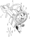
- a wheelchair restraint apparatus 1 shown in FIG. 1 is an apparatus for restraining a wheelchair 102 in a vehicle.
- the wheelchair restraint apparatus 1 includes a vehicle seat 2, and a slide mechanism 3.
- Examples of the vehicle in which the wheelchair restraint apparatus 1 is installed may include, automobiles, railroad vehicles, ships, boats, and aircrafts.
- Directions defined in the description hereafter and in the accompanying drawings correspond to directions from the vehicle seat 2.
- Front-rear directions, width directions, and up-down directions from the wheelchair 102 restrained to the vehicle seat 2 respectively correspond to front-rear directions, width directions, and up-down directions from the vehicle seat 2.
- the vehicle seat 2 is used as a seating in the vehicle and also serves as the main body to restrain the wheelchair 102 in the wheelchair restraint apparatus 1.
- the vehicle seat 2 includes a seat cushion 2A, a seatback 2B, a first leg 2C, a second leg 2D, a seat belt 2E (see FIG. 1 ), a belt buckle 2F, and a restraint mechanism 2G.
- the seat cushion 2A is a part that supports the buttocks of an occupant of the vehicle seat 2.
- the seatback 2B is a part that supports the back of the occupant of the vehicle seat 2.
- the seat cushion 2A is flipped up when the wheelchair 102 is restrained. In other words, the seat cushion 2A is configured to pivotally move between its seating position and flipped position.
- the first leg 2C and the second leg 2D support the seat cushion 2A and the seatback 2B.
- the first leg 2C and the second leg 2D are arranged apart from each other in the width directions.
- the first leg 2C is disposed on the left side of the second leg 2D.
- the first leg 2C and the second leg 2D are attached to the slide mechanism 3.
- the seat belt 2E shown in FIG. 1 is retained by the seatback 2B.
- the seat belt 2E has a (latch) plate, which can be fastened to and detached from the belt buckle 2F, disposed on an outer side of the seat cushion 2A in the width directions.
- the seat belt 2E extends from one shoulder portion of the seatback 2B to the belt buckle 2F to be worn by the occupant of the vehicle seat 2. In a state where the wheelchair 102 is restrained to the vehicle seat 2, the seat belt 2E can also be worn by an occupant of the wheelchair 102.
- the restraint mechanism 2G is a part to and from which the wheelchair 102 can be attached and detached.
- the restraint mechanism 2G is configured to restrain the wheelchair 2 in a state where a part of the wheelchair 102 (that is, an insertion portion 102D) is inserted to the restraint mechanism in a traveling direction of the wheelchair 102 (more specifically, in a direction towards which the wheelchair 102 moves in reverse).
- the restraint mechanism 2G is disposed below the seat cushion 2A and the seatback 2B of the vehicle seat 2.
- the restraint mechanism 2G includes a first striker 21A, and a second striker 21B.
- Each of the first striker 21A and the second striker 21B is a rod-like member that extends in the up-down directions.
- the first striker 21A and the second striker 21B are arranged apart from each other in the width directions of the wheelchair 102 restrained to the vehicle seat 2 (that is, in the width directions of the vehicle seat 2).
- the first striker 21A is disposed on the right side of the second striker 21B.
- the first striker 21A and the second striker 21B are arranged to align with each other in the width directions of the vehicle seat 2. In other words, the first striker 21A and the second striker 21B have the same front-rear-direction alignment on the vehicle seat 2.
- first striker 21A and the second striker 21B are disposed between the first leg 2C and the second leg 2D in the width directions of the vehicle seat 2.
- the distance between the first leg 2C and the first striker 21A is the same as the distance between the second leg 2D and the second striker 21B.
- the slide mechanism 3 is configured to cause the vehicle seat 2 to slide with respect to the vehicle.
- the slide mechanism 3 is disposed on a floor surface of the vehicle.
- the slide mechanism 3 is configured to cause the vehicle seat 2 to slide in the front-rear directions.
- the slide mechanism 3 includes a first rail 3A, and a second rail 3B, arranged apart from each other in the width directions of the vehicle seat 2.
- the first leg 2C is retained by the first rail 3A in a slideable manner.
- the second leg 2D is retained by the second rail 3B in a slideable manner.
- the vehicle seat 2 In both an occupied state (that is, a state where a person is seated in the vehicle seat 2) and a state where the wheelchair 102 is restrained, the vehicle seat 2 is slidable in the front-rear directions along the first rail 3A and the second rail 3B.
- Directions of extension of the first rail 3A and the second rail 3B are, for example, the front-rear directions of the vehicle.
- the slide mechanism 3 may be configured to cause the vehicle seat 2 to slide by using, for example, an actuator powered by electricity, air, hydraulic pressure, and the like.
- the slide mechanism 3 may also be configured to cause the vehicle seat 2 to slide manually.
- the wheelchair 102 includes a seat 102A, a first wheel 102B, a second wheel 102C, and an insertion portion 102D.
- the first wheel 102B and the second wheel 102C are each rotatably attached to the seat 102A.
- the first wheel 102B is situated on the left side of the second wheel 102C.
- the seat 102A, the first wheel 102B, and the second wheel 102C are publicly known components for wheelchairs.
- the wheelchair 102 is able to travel in the front-rear directions of the seat 102A.
- the insertion portion 102D is a part restrained by the vehicle seat 2 with its insertion into the restraint mechanism 2G of the vehicle seat 2.
- the insertion portion 102D is disposed between the first wheel 102B and the second wheel 102C in the width directions of the wheelchair 102.
- the insertion portion 102D includes a first latch mechanism 102E, a second latch mechanism 102F, and a release lever 102G.
- the first latch mechanism 102E is configured to retain the first striker 21A of the restraint mechanism 2G in a restraining space.
- the first latch mechanism 102E changes between a locked state, where the first latch mechanism 102E limits a rearward movement of the first striker 21A by closing the restraining space, and an unlocked state, where the first latch mechanism 102E opens the restraining space.
- the first latch mechanism 102E changes to the unlocked state in response to an imposition of a load from the rearward.
- the first striker 21A collides with the front of the first latch mechanism 102E in the locked state, and the restraining space of the first latch mechanism 102E opens. Consequently, the first striker 21A is housed in the restraining space of the first latch mechanism 102E.
- the first latch mechanism 102E is biased from the unlocked state to the locked state by an elastic element.
- this biasing force causes the first latch mechanism 102E to close the restraining space.
- the first striker 21A is locked as a consequence.
- the second latch mechanism 102F is configured to hold the second striker 21B of the restraint mechanism 2G within the restraining space.
- the second latch mechanism 102F is configured in the same manner as the first latch mechanism 102E. In other words, the second latch mechanism 102F changes from the locked state to the unlocked state by a collision with the second striker 21B and is also biased from the unlocked state to the locked state.
- the first striker 21A and the second striker 21B respectively engages with the first latch mechanism 102E and the second latch mechanism 102F. This causes the insertion portion 102D of the wheelchair 102 to be restrained by the restraint mechanism 2G.
- the first latch mechanism 102E and the second latch mechanism 102F are coupled to the release lever 102G. Manipulation of the release lever 102G causes the first latch mechanism 102E and the second latch mechanism 102F to change from the locked state to the unlocked state.
- the wheelchair 102 is caused to slide by the slide mechanism 3 together with the vehicle seat 2 in the front-rear directions. This enables the vehicle seat 2 to slide to a spacious area in the vehicle to restrain the wheelchair 102 and then slide to any desired position with the wheelchair 102.
- the seat belt 2E disposed in the vehicle seat 2 can be used for the wheelchair 102. Consequently, it eliminates the necessity of providing the vehicle with a dedicated seat belt for wheelchairs.
- a wheelchair restraint apparatus 1A shown in FIG. 5 is an apparatus for restraining the wheelchair 102 in a vehicle.
- the wheelchair restraint apparatus 1A includes the vehicle seat 2, the slide mechanism 3, and a rotation mechanism 5.
- the vehicle seat 2 and the slide mechanism 3 of the wheelchair restraint apparatus 1A are the same as those of the wheelchair restraint apparatus 1 shown in FIG. 1 .
- the wheelchair restraint apparatus 1A is the wheelchair restraint apparatus 1 in FIG. 1 with the rotation mechanism 5.
- the rotation mechanism 5 is configured to cause the vehicle seat 2 to rotate with respect to the vehicle.
- the rotation mechanism 5 includes an upper portion 51, and a lower portion 52.
- the upper portion 51 is fixed to the vehicle seat 2 (more specifically, to the first leg 2C and the second leg 2D).
- the lower portion 52 is retained by the slide mechanism 3 in a slideable manner.
- the lower portion 52 retains the upper portion 51 such that the upper portion 51 is rotatable about a rotation shaft, which extends parallel with the up-down directions.
- a rotation of the upper portion 51 with respect to the lower portion 52 causes the vehicle seat 2 to rotate with respect to the slide mechanism 3 and the floor surface of the vehicle.
- the rotation mechanism 5 causes the vehicle seat 2 to change its orientation such that the front-rear directions of the vehicle seat 2 intersects the sliding directions of the slide mechanism 3 (that is, the directions of extension of the first rail 3A and the second rail 3B).
- the vehicle seat 2 can slide while being oriented such that its front-rear directions are intersecting the sliding directions.
- the vehicle seat 2 is rotatable in both an occupied state (that is, a state where a person is seated in the vehicle seat 2) and a state where the wheelchair 102 is restrained.
- the wheelchair 102 can be restrained to the vehicle seat 2 after the vehicle seat 2 is rotated to be oriented such that the wheelchair 102 is easily restrained, and then the vehicle seat 2 and the wheelchair 102 can be rotated to any desirable orientation.
- the restraint mechanism of the vehicle seat and the configuration of the insertion portion of the wheelchair are merely examples.
- the insertion portion may also be fixed to the restraint mechanism by a structure other than a latch.
- the main body to which the wheelchair is restrained does not necessarily have to be the vehicle seat.
- the main body may be a structure or component other than the vehicle seat, such as a wall and a frame body installed in the vehicle.
- such structure or component that serves as the main body of the wheelchair restraint apparatus has a seat belt installed and is attached to the slide mechanism.
- Functions of one element in the aforementioned embodiments may be achieved by two or more elements. Functions of two or more elements may be integrated into one element. A part of the configuration in the aforementioned embodiments may be omitted. At least a part of the configuration in the aforementioned embodiments may be added to or replaced with other part of the configuration in the aforementioned embodiments. It should be noted that any and all modes included in the technical ideas that are identified by the languages recited in the claims are embodiments of the present disclosure.
Landscapes
- Health & Medical Sciences (AREA)
- Public Health (AREA)
- Life Sciences & Earth Sciences (AREA)
- Animal Behavior & Ethology (AREA)
- General Health & Medical Sciences (AREA)
- Veterinary Medicine (AREA)
- Seats For Vehicles (AREA)
- Passenger Equipment (AREA)
- Fittings On The Vehicle Exterior For Carrying Loads, And Devices For Holding Or Mounting Articles (AREA)
Abstract
Description
- The present disclosure relates to a wheelchair restraint apparatus.
- A system that provides an occupant of a wheelchair, restrained inside a vehicle such as a passenger car and the like, with a seat belt used in the vehicle is known (see
Japanese Unexamined Patent Application Publication No. 2021-030877 - To make a seat belt installed in a vehicle available also for a wheelchair, it is necessary to precisely adjust a restraining position of the wheelchair (particularly, alignment in width directions of the wheelchair). Depending on the restraining position, a space for handling the wheelchair may be too small to place the wheelchair in position without any problems.
- In one aspect of the present disclosure, it is preferable to provide a wheelchair restraint apparatus that renders easy adjustment of the restraining position of a wheelchair inside a vehicle.
- One aspect of the present disclosure is a wheelchair restraint apparatus configured to restrain a wheelchair inside a vehicle. The wheelchair restraint apparatus includes a main body having a seat belt, and a restraint mechanism to and from which the wheelchair is attachable and detachable; and a slide mechanism configured to cause the main body to slide with respect to the vehicle. The restraint mechanism is configured to restrain the wheelchair in a state where a part of the wheelchair is inserted to the restraint mechanism in a traveling direction of the wheelchair.
- Such configuration enables positioning of the wheelchair with the main body of the wheelchair restraint apparatus by inserting a part of the wheelchair to the restraint mechanism in the traveling direction of the wheelchair. In addition, because the main body to which the wheelchair is restrained is made slideable, the wheelchair can be restrained after the main body has been moved to a position where the wheelchair can be easily handled. Owing to the above, the adjustment of the restraining position of the wheelchair in the vehicle is facilitated, and an occupant of the wheelchair can appropriately use the seat belt disposed in the main body.
- In one aspect of the present disclosure, the wheelchair restraint mechanism may further include a rotation mechanism configured to cause the main body to rotate with respect to the vehicle. Such configuration enables adjustment of an insertion direction of the wheelchair to the main body. This consequently further facilitates the adjustment of the restraining position of the wheelchair in the vehicle.
- In one aspect of the present disclosure, the main body may be a vehicle seat. Such configuration enables a use of the seat belt disposed in the vehicle seat for the wheelchair. Consequently, it eliminates the necessity of providing the vehicle with a dedicated seat belt for wheelchairs.
- An example embodiment of the present disclosure will be described hereinafter by way of example with reference to the accompanying drawings, in which:
-
FIG. 1 is a schematic perspective view of a wheelchair restraint apparatus of an embodiment; -
FIG. 2 is a schematic perspective view of a vehicle seat of the wheelchair restraint apparatus inFIG. 1 ; -
FIG. 3 is a schematic perspective view of an engagement target portion of the vehicle seat inFIG. 2 ; -
FIG. 4 is a schematic perspective view of the wheelchair of the wheelchair restraint apparatus inFIG. 1 ; -
FIG. 5 is a schematic side view of a wheelchair restraint apparatus of an embodiment different from the embodiment inFIG. 1 ; and -
FIG. 6 is a schematic plan view of the wheelchair restraint apparatus inFIG. 5 . - A wheelchair restraint apparatus 1 shown in
FIG. 1 is an apparatus for restraining awheelchair 102 in a vehicle. The wheelchair restraint apparatus 1 includes a vehicle seat 2, and aslide mechanism 3. - Examples of the vehicle in which the wheelchair restraint apparatus 1 is installed may include, automobiles, railroad vehicles, ships, boats, and aircrafts. Directions defined in the description hereafter and in the accompanying drawings correspond to directions from the vehicle seat 2. Front-rear directions, width directions, and up-down directions from the
wheelchair 102 restrained to the vehicle seat 2 respectively correspond to front-rear directions, width directions, and up-down directions from the vehicle seat 2. - The vehicle seat 2 is used as a seating in the vehicle and also serves as the main body to restrain the
wheelchair 102 in the wheelchair restraint apparatus 1. - As shown in
FIG. 2 , the vehicle seat 2 includes aseat cushion 2A, aseatback 2B, afirst leg 2C, asecond leg 2D, aseat belt 2E (seeFIG. 1 ), abelt buckle 2F, and arestraint mechanism 2G. - The
seat cushion 2A is a part that supports the buttocks of an occupant of the vehicle seat 2. Theseatback 2B is a part that supports the back of the occupant of the vehicle seat 2. As shown inFIG. 2 , theseat cushion 2A is flipped up when thewheelchair 102 is restrained. In other words, theseat cushion 2A is configured to pivotally move between its seating position and flipped position. - The
first leg 2C and thesecond leg 2D support theseat cushion 2A and theseatback 2B. Thefirst leg 2C and thesecond leg 2D are arranged apart from each other in the width directions. Thefirst leg 2C is disposed on the left side of thesecond leg 2D. Thefirst leg 2C and thesecond leg 2D are attached to theslide mechanism 3. - The
seat belt 2E shown inFIG. 1 is retained by theseatback 2B. Theseat belt 2E has a (latch) plate, which can be fastened to and detached from thebelt buckle 2F, disposed on an outer side of theseat cushion 2A in the width directions. - The
seat belt 2E extends from one shoulder portion of theseatback 2B to thebelt buckle 2F to be worn by the occupant of the vehicle seat 2. In a state where thewheelchair 102 is restrained to the vehicle seat 2, theseat belt 2E can also be worn by an occupant of thewheelchair 102. - The
restraint mechanism 2G is a part to and from which thewheelchair 102 can be attached and detached. Therestraint mechanism 2G is configured to restrain the wheelchair 2 in a state where a part of the wheelchair 102 (that is, aninsertion portion 102D) is inserted to the restraint mechanism in a traveling direction of the wheelchair 102 (more specifically, in a direction towards which thewheelchair 102 moves in reverse). - As shown in
FIG. 3 , therestraint mechanism 2G is disposed below theseat cushion 2A and theseatback 2B of the vehicle seat 2. Therestraint mechanism 2G includes afirst striker 21A, and asecond striker 21B. - Each of the
first striker 21A and thesecond striker 21B is a rod-like member that extends in the up-down directions. Thefirst striker 21A and thesecond striker 21B are arranged apart from each other in the width directions of thewheelchair 102 restrained to the vehicle seat 2 (that is, in the width directions of the vehicle seat 2). - The
first striker 21A is disposed on the right side of thesecond striker 21B. Thefirst striker 21A and thesecond striker 21B are arranged to align with each other in the width directions of the vehicle seat 2. In other words, thefirst striker 21A and thesecond striker 21B have the same front-rear-direction alignment on the vehicle seat 2. - In addition, the
first striker 21A and thesecond striker 21B are disposed between thefirst leg 2C and thesecond leg 2D in the width directions of the vehicle seat 2. The distance between thefirst leg 2C and thefirst striker 21A is the same as the distance between thesecond leg 2D and thesecond striker 21B. - The
slide mechanism 3 is configured to cause the vehicle seat 2 to slide with respect to the vehicle. Theslide mechanism 3 is disposed on a floor surface of the vehicle. - More specifically, the
slide mechanism 3 is configured to cause the vehicle seat 2 to slide in the front-rear directions. Theslide mechanism 3 includes afirst rail 3A, and asecond rail 3B, arranged apart from each other in the width directions of the vehicle seat 2. Thefirst leg 2C is retained by thefirst rail 3A in a slideable manner. Thesecond leg 2D is retained by thesecond rail 3B in a slideable manner. - In both an occupied state (that is, a state where a person is seated in the vehicle seat 2) and a state where the
wheelchair 102 is restrained, the vehicle seat 2 is slidable in the front-rear directions along thefirst rail 3A and thesecond rail 3B. Directions of extension of thefirst rail 3A and thesecond rail 3B (that is, sliding directions of the vehicle seat 2) are, for example, the front-rear directions of the vehicle. - The
slide mechanism 3 may be configured to cause the vehicle seat 2 to slide by using, for example, an actuator powered by electricity, air, hydraulic pressure, and the like. Theslide mechanism 3 may also be configured to cause the vehicle seat 2 to slide manually. - As shown in
FIG. 4 , thewheelchair 102 includes aseat 102A, afirst wheel 102B, asecond wheel 102C, and aninsertion portion 102D. - The
first wheel 102B and thesecond wheel 102C are each rotatably attached to theseat 102A. Thefirst wheel 102B is situated on the left side of thesecond wheel 102C. Theseat 102A, thefirst wheel 102B, and thesecond wheel 102C are publicly known components for wheelchairs. Thewheelchair 102 is able to travel in the front-rear directions of theseat 102A. - The
insertion portion 102D is a part restrained by the vehicle seat 2 with its insertion into therestraint mechanism 2G of the vehicle seat 2. Theinsertion portion 102D is disposed between thefirst wheel 102B and thesecond wheel 102C in the width directions of thewheelchair 102. Theinsertion portion 102D includes afirst latch mechanism 102E, asecond latch mechanism 102F, and arelease lever 102G. - The
first latch mechanism 102E is configured to retain thefirst striker 21A of therestraint mechanism 2G in a restraining space. Thefirst latch mechanism 102E changes between a locked state, where thefirst latch mechanism 102E limits a rearward movement of thefirst striker 21A by closing the restraining space, and an unlocked state, where thefirst latch mechanism 102E opens the restraining space. - In the locked state, the
first latch mechanism 102E changes to the unlocked state in response to an imposition of a load from the rearward. Thus, as thewheelchair 102 moves to the rear towards the vehicle seat 2, thefirst striker 21A collides with the front of thefirst latch mechanism 102E in the locked state, and the restraining space of thefirst latch mechanism 102E opens. Consequently, thefirst striker 21A is housed in the restraining space of thefirst latch mechanism 102E. - The
first latch mechanism 102E is biased from the unlocked state to the locked state by an elastic element. Thus, when thefirst latch mechanism 102E is released from the load while thefirst striker 21A is housed in the restraining space, this biasing force causes thefirst latch mechanism 102E to close the restraining space. Thefirst striker 21A is locked as a consequence. - The
second latch mechanism 102F is configured to hold thesecond striker 21B of therestraint mechanism 2G within the restraining space. Thesecond latch mechanism 102F is configured in the same manner as thefirst latch mechanism 102E. In other words, thesecond latch mechanism 102F changes from the locked state to the unlocked state by a collision with thesecond striker 21B and is also biased from the unlocked state to the locked state. - By causing the
wheelchair 102 to move in reverse from a location ahead of the vehicle seat 2 towards the vehicle seat 2, thefirst striker 21A and thesecond striker 21B respectively engages with thefirst latch mechanism 102E and thesecond latch mechanism 102F. This causes theinsertion portion 102D of thewheelchair 102 to be restrained by therestraint mechanism 2G. - The
first latch mechanism 102E and thesecond latch mechanism 102F are coupled to therelease lever 102G. Manipulation of therelease lever 102G causes thefirst latch mechanism 102E and thesecond latch mechanism 102F to change from the locked state to the unlocked state. - When the occupant of the
wheelchair 102 restrained to the vehicle seat 2 moves thewheelchair 102 forward while manipulating therelease lever 102G, thewheelchair 102 is released from the vehicle seat 2. When the manipulation of therelease lever 102G is stopped, thefirst latch mechanism 102E and thesecond latch mechanism 102F return to the locked sate by the biasing force. - In a state where the
insertion portion 102D is restrained by therestraint mechanism 2G of the vehicle seat 2, thewheelchair 102 is caused to slide by theslide mechanism 3 together with the vehicle seat 2 in the front-rear directions. This enables the vehicle seat 2 to slide to a spacious area in the vehicle to restrain thewheelchair 102 and then slide to any desired position with thewheelchair 102. - According to the embodiment explained above in detail, the following effects can be obtained.
- (1a) By inserting a part of the wheelchair 102 (that is, the
insertion portion 102D) to therestraint mechanism 2G in the traveling direction of thewheelchair 102, positioning of thewheelchair 102 with the vehicle seat 2, which is the main body of the wheelchair restraint apparatus 1, can be enabled. In addition, since the vehicle seat 2, to which thewheelchair 102 is restrained, is made slideable, thewheelchair 102 can be restrained after the vehicle seat 2 has been moved to a position where thewheelchair 102 can be easily handled. Owing to the above, the adjustment of the restraining position of thewheelchair 102 in the vehicle is facilitated, and the occupant of thewheelchair 102 can appropriately use theseat belt 2E disposed in the vehicle seat 2. - (1b) By having the vehicle seat 2 serve as the main body of the wheelchair restraint apparatus 1, the
seat belt 2E disposed in the vehicle seat 2 can be used for thewheelchair 102. Consequently, it eliminates the necessity of providing the vehicle with a dedicated seat belt for wheelchairs. - A
wheelchair restraint apparatus 1A shown inFIG. 5 is an apparatus for restraining thewheelchair 102 in a vehicle. - The
wheelchair restraint apparatus 1A includes the vehicle seat 2, theslide mechanism 3, and arotation mechanism 5. The vehicle seat 2 and theslide mechanism 3 of thewheelchair restraint apparatus 1A are the same as those of the wheelchair restraint apparatus 1 shown inFIG. 1 . In other words, thewheelchair restraint apparatus 1A is the wheelchair restraint apparatus 1 inFIG. 1 with therotation mechanism 5. - The
rotation mechanism 5 is configured to cause the vehicle seat 2 to rotate with respect to the vehicle. Therotation mechanism 5 includes anupper portion 51, and alower portion 52. - The
upper portion 51 is fixed to the vehicle seat 2 (more specifically, to thefirst leg 2C and thesecond leg 2D). Thelower portion 52 is retained by theslide mechanism 3 in a slideable manner. Thelower portion 52 retains theupper portion 51 such that theupper portion 51 is rotatable about a rotation shaft, which extends parallel with the up-down directions. - A rotation of the
upper portion 51 with respect to thelower portion 52 causes the vehicle seat 2 to rotate with respect to theslide mechanism 3 and the floor surface of the vehicle. As shown inFIG. 6 , therotation mechanism 5 causes the vehicle seat 2 to change its orientation such that the front-rear directions of the vehicle seat 2 intersects the sliding directions of the slide mechanism 3 (that is, the directions of extension of thefirst rail 3A and thesecond rail 3B). In addition, the vehicle seat 2 can slide while being oriented such that its front-rear directions are intersecting the sliding directions. - The vehicle seat 2 is rotatable in both an occupied state (that is, a state where a person is seated in the vehicle seat 2) and a state where the
wheelchair 102 is restrained. Thus, thewheelchair 102 can be restrained to the vehicle seat 2 after the vehicle seat 2 is rotated to be oriented such that thewheelchair 102 is easily restrained, and then the vehicle seat 2 and thewheelchair 102 can be rotated to any desirable orientation. - According to the embodiment that has been explained above in detail, the following effect can be obtained.
- (2a) The insertion direction of the
wheelchair 102 to the vehicle seat 2 can be adjusted. This further facilitates the adjustment of the restraining position of thewheelchair 102 in the vehicle. - An embodiment of the present disclosure has been explained above. Nevertheless, the present disclosure can be carried out in various modifications without being limited to the aforementioned embodiments.
- (3a) In the wheelchair restraint apparatus of the aforementioned embodiments, the restraint mechanism of the vehicle seat and the configuration of the insertion portion of the wheelchair are merely examples. For example, the insertion portion may also be fixed to the restraint mechanism by a structure other than a latch.
- (3b) In the wheelchair restraint apparatus of the aforementioned embodiments, the main body to which the wheelchair is restrained does not necessarily have to be the vehicle seat. For example, the main body may be a structure or component other than the vehicle seat, such as a wall and a frame body installed in the vehicle. In this case, such structure or component that serves as the main body of the wheelchair restraint apparatus has a seat belt installed and is attached to the slide mechanism.
- (3c) Functions of one element in the aforementioned embodiments may be achieved by two or more elements. Functions of two or more elements may be integrated into one element. A part of the configuration in the aforementioned embodiments may be omitted. At least a part of the configuration in the aforementioned embodiments may be added to or replaced with other part of the configuration in the aforementioned embodiments. It should be noted that any and all modes included in the technical ideas that are identified by the languages recited in the claims are embodiments of the present disclosure.
Claims (3)
- A wheelchair restraint apparatus (1) configured to restrain a wheelchair (102) inside a vehicle, the apparatus comprising:a main body (2) comprising:a seat belt (2E), anda restraint mechanism (2G) to and from which the wheelchair is attachable and detachable; anda slide mechanism (3) configured to cause the main body to slide with respect to the vehicle,wherein the restraint mechanism is configured to restrain the wheelchair in a state where a part of the wheelchair is inserted to the restraint mechanism in a traveling direction of the wheelchair.
- The wheelchair restraint apparatus (1A) according to claim 1, further comprising a rotation mechanism (5) configured to cause the main body to rotate with respect to the vehicle.
- The wheelchair restraint apparatus according to claim 1 or 2, wherein the main body is a vehicle seat.
Applications Claiming Priority (1)
| Application Number | Priority Date | Filing Date | Title |
|---|---|---|---|
| US17/545,732 US12274651B2 (en) | 2021-12-08 | 2021-12-08 | Wheelchair restraint apparatus |
Publications (2)
| Publication Number | Publication Date |
|---|---|
| EP4193981A2 true EP4193981A2 (en) | 2023-06-14 |
| EP4193981A3 EP4193981A3 (en) | 2023-06-21 |
Family
ID=84360414
Family Applications (1)
| Application Number | Title | Priority Date | Filing Date |
|---|---|---|---|
| EP22208310.7A Pending EP4193981A3 (en) | 2021-12-08 | 2022-11-18 | Wheelchair restraint apparatus |
Country Status (4)
| Country | Link |
|---|---|
| US (1) | US12274651B2 (en) |
| EP (1) | EP4193981A3 (en) |
| JP (1) | JP7806664B2 (en) |
| CN (1) | CN116236348A (en) |
Families Citing this family (3)
| Publication number | Priority date | Publication date | Assignee | Title |
|---|---|---|---|---|
| GB2602064B (en) * | 2020-12-17 | 2023-05-10 | Priestman Goode Ltd | Vehicle seat for accommodating a wheelchair |
| US12274651B2 (en) * | 2021-12-08 | 2025-04-15 | Toyota Boshoku Kabushiki Kaisha | Wheelchair restraint apparatus |
| US12090097B2 (en) * | 2023-01-31 | 2024-09-17 | The Boeing Company | Platform system for securing a wheelchair in position within an internal cabin of a vehicle |
Citations (2)
| Publication number | Priority date | Publication date | Assignee | Title |
|---|---|---|---|---|
| US7641257B2 (en) * | 2005-09-22 | 2010-01-05 | Nmi Safety Systems Ltd. | Seating arrangement |
| JP2021030877A (en) | 2019-08-23 | 2021-03-01 | トヨタ自動車株式会社 | Vehicle interlock system |
Family Cites Families (16)
| Publication number | Priority date | Publication date | Assignee | Title |
|---|---|---|---|---|
| GB2176154B (en) | 1985-01-04 | 1988-05-25 | Unwin C N Ltds | Improvements relating to wheelchair restraints |
| GB2197628B (en) | 1986-11-14 | 1991-01-02 | Unwin C N Ltds | Improvements relating to dual purpose seat structures |
| US7229238B2 (en) * | 2004-03-25 | 2007-06-12 | Valeda Company Llc | Wheelchair docking system |
| GB2425721A (en) | 2005-05-04 | 2006-11-08 | Nmi Safety Systems Ltd | Vehicle seat with lateral and rotational movement with detachable squab |
| DE202005016461U1 (en) | 2005-10-19 | 2007-03-01 | Apener Maschinenbau und Förderanlagen Gustav Bruns GmbH & Co KG | back assembly |
| CN102038585B (en) * | 2010-11-01 | 2012-04-18 | 胡达广 | Self-location wheelchair carrying platform |
| NL1039037C2 (en) | 2011-09-15 | 2013-03-18 | Beheers En Beleggingsmij Verachtert B V | Safety-belt system in transport vehicles for able and disabled people. |
| CN105559985B (en) * | 2016-01-23 | 2017-11-07 | 长沙学院 | A kind of operator seat wheelchair-fixing device |
| JP6318439B2 (en) * | 2016-06-21 | 2018-05-09 | 本田技研工業株式会社 | Vehicle seat device |
| US10953987B2 (en) * | 2018-07-31 | 2021-03-23 | B/E Aerospace, Inc. | Aircraft interior configuration with flexible use space |
| DE202018003604U1 (en) * | 2018-08-03 | 2018-10-19 | Dittrich Werkzeug- und Formenbau GmbH | Retaining device for a wheelchair, in particular for a caregiver wheelchair, in a vehicle |
| JP7124603B2 (en) * | 2018-09-26 | 2022-08-24 | トヨタ自動車株式会社 | VEHICLE SEAT AND VEHICLE SEAT ARRANGEMENT STRUCTURE |
| US20200172225A1 (en) * | 2018-12-03 | 2020-06-04 | B/E Aerospace, Inc. | Aisle track system for aircraft and accessible lavatory configuration |
| GB2602064B (en) * | 2020-12-17 | 2023-05-10 | Priestman Goode Ltd | Vehicle seat for accommodating a wheelchair |
| US12274651B2 (en) * | 2021-12-08 | 2025-04-15 | Toyota Boshoku Kabushiki Kaisha | Wheelchair restraint apparatus |
| US12279997B2 (en) * | 2021-12-08 | 2025-04-22 | Toyota Boshoku Kabushiki Kaisha | Wheelchair restraint mechanism |
-
2021
- 2021-12-08 US US17/545,732 patent/US12274651B2/en active Active
-
2022
- 2022-11-15 JP JP2022182645A patent/JP7806664B2/en active Active
- 2022-11-18 EP EP22208310.7A patent/EP4193981A3/en active Pending
- 2022-12-06 CN CN202211555976.6A patent/CN116236348A/en active Pending
Patent Citations (2)
| Publication number | Priority date | Publication date | Assignee | Title |
|---|---|---|---|---|
| US7641257B2 (en) * | 2005-09-22 | 2010-01-05 | Nmi Safety Systems Ltd. | Seating arrangement |
| JP2021030877A (en) | 2019-08-23 | 2021-03-01 | トヨタ自動車株式会社 | Vehicle interlock system |
Also Published As
| Publication number | Publication date |
|---|---|
| US20230172776A1 (en) | 2023-06-08 |
| CN116236348A (en) | 2023-06-09 |
| US12274651B2 (en) | 2025-04-15 |
| JP2023085216A (en) | 2023-06-20 |
| EP4193981A3 (en) | 2023-06-21 |
| JP7806664B2 (en) | 2026-01-27 |
Similar Documents
| Publication | Publication Date | Title |
|---|---|---|
| US12274651B2 (en) | Wheelchair restraint apparatus | |
| US11123241B2 (en) | Vehicle seat and vehicle seat arrangement structure | |
| EP2269863B1 (en) | Stowable vehicle seat | |
| US10336215B2 (en) | Movable vehicle seat with integrated occupant restraint system | |
| JP3722798B2 (en) | Vehicle seat with folding position | |
| CN110293887B (en) | Seat structure for vehicle | |
| US7726730B2 (en) | Passenger seat device for motor vehicles | |
| US7252318B2 (en) | Seat device for vehicle | |
| US11583456B2 (en) | Wheelchair passenger restraint structure | |
| US8573699B2 (en) | Vehicle seat | |
| EP4193980A1 (en) | Wheelchair restraint mechanism | |
| CN111532236A (en) | Vehicle restraint system | |
| JP6992858B2 (en) | Vehicle seat structure | |
| JPWO2014192095A1 (en) | Vehicle seat | |
| KR20240027458A (en) | Rear seat for vehicle | |
| CN113619522A (en) | Seatbelt device for vehicle seat and vehicle including the same | |
| CZ28740U1 (en) | Car rear seat positioning device | |
| JP2007145302A (en) | Occupant restraint device | |
| EP2595844B1 (en) | A seat belt arrangement | |
| GB2293318A (en) | vehicle seat assembly with safety beam | |
| JP4156872B2 (en) | Vehicle seat group | |
| CN101312848B (en) | Mechanism for locking the track of a motor vehicle seat | |
| JPH10287157A (en) | Vehicular seat | |
| SE2451297A1 (en) | Vehicle cab with door locking system | |
| JPH0249071Y2 (en) |
Legal Events
| Date | Code | Title | Description |
|---|---|---|---|
| PUAI | Public reference made under article 153(3) epc to a published international application that has entered the european phase |
Free format text: ORIGINAL CODE: 0009012 |
|
| STAA | Information on the status of an ep patent application or granted ep patent |
Free format text: STATUS: REQUEST FOR EXAMINATION WAS MADE |
|
| PUAL | Search report despatched |
Free format text: ORIGINAL CODE: 0009013 |
|
| 17P | Request for examination filed |
Effective date: 20221118 |
|
| AK | Designated contracting states |
Kind code of ref document: A2 Designated state(s): AL AT BE BG CH CY CZ DE DK EE ES FI FR GB GR HR HU IE IS IT LI LT LU LV MC ME MK MT NL NO PL PT RO RS SE SI SK SM TR |
|
| AK | Designated contracting states |
Kind code of ref document: A3 Designated state(s): AL AT BE BG CH CY CZ DE DK EE ES FI FR GB GR HR HU IE IS IT LI LT LU LV MC ME MK MT NL NO PL PT RO RS SE SI SK SM TR |
|
| RIC1 | Information provided on ipc code assigned before grant |
Ipc: A61G 3/08 20060101AFI20230515BHEP |
|
| STAA | Information on the status of an ep patent application or granted ep patent |
Free format text: STATUS: EXAMINATION IS IN PROGRESS |
|
| 17Q | First examination report despatched |
Effective date: 20250729 |