EP4193853A1 - Aerosol generating device - Google Patents
Aerosol generating device Download PDFInfo
- Publication number
- EP4193853A1 EP4193853A1 EP21952125.9A EP21952125A EP4193853A1 EP 4193853 A1 EP4193853 A1 EP 4193853A1 EP 21952125 A EP21952125 A EP 21952125A EP 4193853 A1 EP4193853 A1 EP 4193853A1
- Authority
- EP
- European Patent Office
- Prior art keywords
- resonance
- aerosol generation
- pillar
- lead
- chamber
- Prior art date
- Legal status (The legal status is an assumption and is not a legal conclusion. Google has not performed a legal analysis and makes no representation as to the accuracy of the status listed.)
- Pending
Links
Images




Classifications
-
- A—HUMAN NECESSITIES
- A24—TOBACCO; CIGARS; CIGARETTES; SIMULATED SMOKING DEVICES; SMOKERS' REQUISITES
- A24F—SMOKERS' REQUISITES; MATCH BOXES; SIMULATED SMOKING DEVICES
- A24F40/00—Electrically operated smoking devices; Component parts thereof; Manufacture thereof; Maintenance or testing thereof; Charging means specially adapted therefor
- A24F40/40—Constructional details, e.g. connection of cartridges and battery parts
- A24F40/46—Shape or structure of electric heating means
-
- A—HUMAN NECESSITIES
- A24—TOBACCO; CIGARS; CIGARETTES; SIMULATED SMOKING DEVICES; SMOKERS' REQUISITES
- A24F—SMOKERS' REQUISITES; MATCH BOXES; SIMULATED SMOKING DEVICES
- A24F40/00—Electrically operated smoking devices; Component parts thereof; Manufacture thereof; Maintenance or testing thereof; Charging means specially adapted therefor
- A24F40/50—Control or monitoring
- A24F40/51—Arrangement of sensors
-
- H—ELECTRICITY
- H05—ELECTRIC TECHNIQUES NOT OTHERWISE PROVIDED FOR
- H05B—ELECTRIC HEATING; ELECTRIC LIGHT SOURCES NOT OTHERWISE PROVIDED FOR; CIRCUIT ARRANGEMENTS FOR ELECTRIC LIGHT SOURCES, IN GENERAL
- H05B6/00—Heating by electric, magnetic or electromagnetic fields
- H05B6/64—Heating using microwaves
- H05B6/6447—Method of operation or details of the microwave heating apparatus related to the use of detectors or sensors
-
- H—ELECTRICITY
- H05—ELECTRIC TECHNIQUES NOT OTHERWISE PROVIDED FOR
- H05B—ELECTRIC HEATING; ELECTRIC LIGHT SOURCES NOT OTHERWISE PROVIDED FOR; CIRCUIT ARRANGEMENTS FOR ELECTRIC LIGHT SOURCES, IN GENERAL
- H05B6/00—Heating by electric, magnetic or electromagnetic fields
- H05B6/64—Heating using microwaves
- H05B6/72—Radiators or antennas
-
- H—ELECTRICITY
- H05—ELECTRIC TECHNIQUES NOT OTHERWISE PROVIDED FOR
- H05B—ELECTRIC HEATING; ELECTRIC LIGHT SOURCES NOT OTHERWISE PROVIDED FOR; CIRCUIT ARRANGEMENTS FOR ELECTRIC LIGHT SOURCES, IN GENERAL
- H05B6/00—Heating by electric, magnetic or electromagnetic fields
- H05B6/64—Heating using microwaves
- H05B6/80—Apparatus for specific applications
-
- H—ELECTRICITY
- H05—ELECTRIC TECHNIQUES NOT OTHERWISE PROVIDED FOR
- H05B—ELECTRIC HEATING; ELECTRIC LIGHT SOURCES NOT OTHERWISE PROVIDED FOR; CIRCUIT ARRANGEMENTS FOR ELECTRIC LIGHT SOURCES, IN GENERAL
- H05B6/00—Heating by electric, magnetic or electromagnetic fields
- H05B6/64—Heating using microwaves
- H05B6/80—Apparatus for specific applications
- H05B6/802—Apparatus for specific applications for heating fluids
-
- A—HUMAN NECESSITIES
- A24—TOBACCO; CIGARS; CIGARETTES; SIMULATED SMOKING DEVICES; SMOKERS' REQUISITES
- A24F—SMOKERS' REQUISITES; MATCH BOXES; SIMULATED SMOKING DEVICES
- A24F40/00—Electrically operated smoking devices; Component parts thereof; Manufacture thereof; Maintenance or testing thereof; Charging means specially adapted therefor
- A24F40/20—Devices using solid inhalable precursors
Definitions
- the present invention relates to the technical field of electronic atomization, and more particularly to an aerosol generation device.
- a heat-not-burning (HNB) device is a kind of combination equipment including a heating device combined with an aerosol generation substance (such as a product of processed plant leaves).
- An external heating device heats, at a high temperature, the aerosol generation substance to a temperature that can generate an aerosol, but is not sufficient to cause burning, so that, without being caused to burn, the aerosol generation substance generates an aerosol desired by a user.
- the heat-not-burning devices that are currently available in the market generally adopts resistor heating means, namely a centered heating plate or a heating pin penetrates, at a center location of the aerosol generation substance, into the interior of the aerosol generation substance to proceed with heating.
- resistor heating means namely a centered heating plate or a heating pin penetrates, at a center location of the aerosol generation substance, into the interior of the aerosol generation substance to proceed with heating.
- Such a utensil takes a long time to wait for preheating before use, making it impossible to freely start or stop vaping, and the aerosol generation substance cannot be uniformly carbonized, leading to insufficient baking of the aerosol generation substance and low efficiency of utilization.
- the heating plate of the HNB utensil may easily cause generation of contaminants, which are hard to cleanse, in an aerosol generation substance extractor and a heating plate holder, and a portion of the aerosol generation substance that is in contact with the heating body may get locally excessively high temperature, causing partial decomposition and releasing substances that are harmful to human bodies.
- the resistor heating means is gradually replaced by microwave heating technology, which becomes a new solution of heating.
- the microwave heating technology has advantages in respect of high efficiency, timeliness, optionality, and non-delay heating, and is only effective of heating for specific substances having certain dielectric properties.
- microwave heating based atomization include: (a) instantaneous vaping or stopping being achievable as the microwave heating is radiation based heating, rather than heat conduction; (b) there being no plate breaking or heating plate cleansing issues as no heating plate is involved; and (c) the utilization efficiency of the aerosol generation substance being high and mouthfeel being consistent, and the mouthfeel being much closer to cigarettes.
- microwaves are often fed from one end into a resonance chamber, and this makes the heating to the aerosol generation substance inside the resonance chamber ununiform.
- the application aims to resolve one of the technical issues that the prior art or the related art is suffering.
- the embodiment of the application provides an aerosol generation device which comprises an enclosure, a resonance chamber arranged in the enclosure, the resonance chamber being capable of receiving and holding therein an aerosol generation substance; a microwave assembly, which is arranged on the enclosure, the microwave assembly being operable to feed microwaves to the interior of the resonance chamber; a resonance pillar, a first end of the resonance pillar connected to the chamber bottom wall of the resonance chamber, a second end of the resonance pillar facing the opening of the resonance chamber; probes, the number of the probes being at least two, the at least two probes arranged at intervals on the resonance pillar, the aerosol generation substance located between the at least two probes.
- the aerosol generation device provided in the application comprises the enclosure, the resonance chamber, the microwave assembly, the resonance pillar, and the probes.
- the resonance chamber is arranged in the enclosure.
- the microwave assembly is mounted on the enclosure, and the microwave assembly is operable to feed the microwaves into the resonance chamber.
- the resonance pillar is disposed inside the resonance chamber, and the resonance pillar has a diameter that is less than an inside diameter of the resonance chamber, and a gap is formed between the external wall of the resonance chamber and the internal wall the resonance chamber. The microwaves fed into the interior of the resonance chamber by the microwave assembly transmits along the resonance pillar.
- the first end of the resonance pillar is connected to the bottom wall of the resonance chamber, and the second end of the resonance pillar faces the opening of the resonance chamber, so that the microwaves so fed can transmit in a direction from the first end of the resonance pillar toward the second end.
- the aerosol generation substance is inserted from the opening of the resonance chamber into the interior of the resonance chamber, and the aerosol generation substance is set at a location of the resonance chamber that is adjacent to the opening.
- the microwaves transmitting through the resonance pillar act on the aerosol generation substance to have the aerosol generation substance heated to atomize.
- the microwaves transmitting through the resonance pillar to the aerosol generation substance act on an end of the aerosol generation substance.
- Plural probes are arranged on the resonance pillar, and the plural probes are distributed on the sidewall of the resonance pillar.
- the aerosol generation substance is located among the plural probes.
- the plural probes are arranged to distributed around the circumferential wall of the aerosol generation device.
- the probes may further transmit the microwaves that transmits through the resonance pillar, and the plural probes transmit the microwaves to circumferential wall locations of the aerosol generation substance, so that during a process of operation of the aerosol generation device, the microwaves transmits through the probes to a circumference of the aerosol generation substance to heat the aerosol generation substance from the circumference thereof, thereby reducing the distance that heat needs to travel inside the aerosol generation substance, and enhancing uniformity of heating to the aerosol generation substance to avoid incomplete heating of the aerosol generation substance and increase the utilization efficiency of the aerosol generation substance.
- the aerosol generation substance is arranged in the form of a bar, and the microwaves are acting on an end of the aerosol generation substance, and heat is conducted from the heated end of the aerosol generation substance toward an opposite end, so that the aerosol generation substance is heated in an incomplete way, and there occurs a problem that atomization is not done completely.
- the embodiment of the application provides the probes arranged to transmit the microwaves to the circumference of the aerosol generation substance, so that the aerosol generation substance can be heated in a more complete way.
- the microwaves are transmitted through the resonance pillar and the probes to the aerosol generation substance, to allow the microwaves to act on the aerosol generation substance.
- the aerosol generation substance absorbs the microwaves, and polar molecules contained in the aerosol generation substance become fast oscillating to convert into thermal energy to thereby heat and atomize the aerosol generation substance.
- a material of the resonance pillar is a metallic material.
- the resonance pillar is made of an elemental metal, such as iron, copper, and aluminum, or the resonance pillar is made of an alloy of iron, copper, and aluminum.
- the aerosol generation device may further comprise the following additional features:
- the at least two probes are uniformly arranged on the circumferential wall of the resonance pillar.
- the number of the probes is plural, and the plural probes are arranged on the circumferential wall of the resonance pillar, and the plural probes surround and define a receiving space.
- the aerosol generation substance is inserted into the resonance chamber, and the aerosol generation substance is located in the receiving space.
- the plural probes are uniformly arranged on the circumferential wall of the resonance pillar, and the plural probes are extended in a direction toward the opening of the resonance chamber, so that the probes are distributed on the circumference of the aerosol generation substance that is inserted into the resonance chamber, to thereby realize that the microwaves act on the aerosol generation substance in plural directions, and locations of action of the microwaves are more uniformly set and thus, uniformity of heating on the aerosol generation substance is enhanced, making the aerosol generation substance more completely atomized and increasing the utilization efficiency of the aerosol generation substance.
- the circumferential wall of the aerosol generation substance is in contact with the plural probes, and the microwaves outputted from the plural probes directly act on the circumferential wall of the aerosol generation substance.
- the microwaves outputted from the plural probes directly act on the circumferential wall of the aerosol generation substance.
- the number of the probes can be selected as two, three, four, five, or six.
- the number of the probes is set to be N, and an included angle between two adjacent probes is equal to 360°/N.
- the probes comprise a connecting portion which is connected to the circumferential wall of the resonance pillar; and an extending portion, a first end of the extending portion connected to the connecting portion, a second end of the extending portion extended in a direction toward the opening of the resonance chamber.
- the probe comprises the connecting portion and the extending portion.
- the probe is mounted to the circumferential wall of the resonance pillar by the connecting portion.
- the extending portion functions to further transmit the microwaves that transmit through the resonance pillar.
- An extending direction of the extending portion is set in a direction toward the opening of the resonance chamber, so as to have the extending portion located on the circumference of the aerosol generation substance to thereby have the aerosol generation substance the circumference uniformly heated.
- the extending portions of the plural probes are all extended in a direction toward the opening of the atomization chamber.
- the length of the extending portions of the plural probes is correspondingly set according to a size of the aerosol generation substance. For example, if the length of the plural probes is set to be relatively great and ends of the plural probes are set at a location that is close to an aerosol outputting portion of the aerosol generation substance, then the microwaves transmitting through the probes may act on the aerosol generation substance closed to the aerosol outputting portion, so as to achieve an effect of fast releasing aerosol in a process of use of the aerosol generation device, and reducing a time interval of preheating the aerosol generation substance.
- an included angle between the connecting portion and the extending portion is in a range from 80° to 100°.
- setting the included angle between the connecting portion and the extending portion to be from 80° to 100° could ensure that the extending portion is arranged in a manner of relatively parallel to the sidewall of the aerosol generation substance, making a distance between the aerosol generation substance and the extending portion relatively short and thus increasing the utilization efficiency of the microwaves transmitting through the probes to the aerosol generation substance.
- the connecting portion is arranged perpendicular to the circumferential wall of the resonance pillar, and the extending portion is arranged parallel with the circumferential wall of the resonance pillar, so that the included angle between the connecting portion and the extending portion is equal to 90°.
- the extending portions of the plural probes are arranged parallel with the circumferential wall of the resonance pillar, and this ensures that the extending portions of the plural probes are of the same distance from the circumferential wall of the aerosol generation substance to thereby further ensure the uniformity of microwave atomization of the aerosol generation substance induced by the microwaves transmitting through the plural probes.
- At least two of the connecting portions are of the same size; and/or at least two of the extending portions are of the same size.
- At least two of the connecting portions are of the same size, which ensures that the distance of the extending portion connected to each of the connecting portions from the resonance pillar is of the same size. Due to the resonance pillar and the aerosol generation substance arranged coaxial with each other, this ensures that the extending portions of the plural probes are of the same distance from the aerosol generation substance to thereby further ensure the uniformity of microwave atomization of the aerosol generation substance induced by the microwaves transmitting through the plural probes.
- the sizes of the extending portions of the plural probes to be the same size, it is possible to ensure that ends of the extending portions of the plural probes are all located on a same cross section of the aerosol generation substance so as to ensure the uniformity of the microwaves outputted therefrom.
- the microwave atomization device further comprises a holder, which is arranged in the resonance chamber, the holder and the resonance pillar arranged to face each other, the at least two probes circumferentially distributed around the circumferential wall of the holder; and an atomization chamber, which is arranged in the holder, the atomization chamber configured for receiving and holding the aerosol generation substance.
- the microwave atomization device further comprises the holder and the atomization chamber.
- the holder is arranged in the resonance chamber, and the atomization chamber is arranged inside the holder.
- An opening is formed in an end of the holder, and the opening is in communication with the atomization chamber.
- the aerosol generation substance is inserted through the opening into the interior of the holder.
- the holder functions to fix the aerosol generation substance in position.
- the aerosol generation substance generates solid or liquid wastes.
- the plural probes are circumferentially distributed around the external wall of the holder, so that the microwaves transmitting through the probes may directly act on the aerosol generation substance inside the atomization chamber of the holder.
- a material of the holder is a low dielectric loss material, such as: microwave-transparent ceramics, glass, and aluminum oxide.
- a center axis of the resonance pillar is coincident with a center axis of the atomization chamber.
- the resonance pillar and the atomization chamber are both of a regular shape.
- the resonance pillar and the atomization chamber are both cylindrical, and the center line of the resonance pillar is coincident with the center line of the atomization chamber, meaning the axis of the resonance pillar is coincident with the axis of the atomization chamber.
- the holder and the enclosure are detachably connected.
- the holder by arranging the holder to be detachably connected with the enclosure, users can individually remove the holder for cleansing. To cleanse off the wastes generated during an atomization process of the aerosol generation substance, it only needs to cleanse the holder that receives and holds the aerosol generation substance, and the electronic components of the aerosol generation device affected in a cleansing operation can be prevented.
- the second end of the resonance pillar and the holder abut on each other.
- the second end of the resonance pillar and the holder abut on each other, so that the distance between the aerosol generation substance and the resonance pillar is the thickness of a bottom wall of the holder.
- Arranging the resonance pillar and the holder to abut on each other could reduce, as much as possible, the spacing distance between the resonance pillar and the aerosol generation substance, and an amount of deterioration of the microwaves are made small in the transmission of the microwave through the resonance pillar.
- the microwave may easily fast deteriorate when transmitting in a gap between the aerosol generation substance and the resonance pillar, so that reducing the spacing distance between the resonance pillar and the aerosol generation substance as much as possible could reduce the amount of deterioration of the microwaves as much as possible to thereby allowing a relatively large amount of the microwaves to act on the aerosol generation substance to increase the heating rate of the aerosol generation substance.
- a cross-sectional area of the resonance pillar is smaller than or equal to a cross-sectional area of the holder.
- a sideway contour edge of the resonance pillar does not extend beyond a sideway contour edge of the holder, and consequently, a projection that the resonance pillar casts on the bottom wall of the resonance chamber falls within a range of a projection that the holder casts on the bottom wall of the resonance chamber, implying the holder is thicker than the resonance pillar.
- the microwaves directly acting on the aerosol generation substance in a condition of being not deteriorated or having a relatively small amount of deterioration, the aerosol generation substance can be heated in a relatively short period of time, thereby increasing the heating rate of the aerosol generation substance and helping achieve instantaneous heating.
- the enclosure comprises a first casing, the resonance pillar arranged in the first casing; and a second casing, which is detachably connected with the first casing.
- the enclosure comprises the first casing and the second casing that are detachably connected.
- the resonance pillar is connected to the bottom wall of an internal-cavity the first casing to allow users to separately cleanse and maintain the first casing and the second casing. And, when the first casing or the second casing is contaminated, it is possible to only replace the first casing or the second casing that has been contaminated, so as to reduce the daily maintenance expenditure of the aerosol generation device.
- the holder and the second casing are fixedly connected with each other, and when it is necessary to cleanse the holder, the second casing can be removed from the first casing, thereby achieving an effect of being easy to cleanse and maintain the first casing and the holder.
- the aerosol generation device comprises: a through hole, which is formed in the casing; and a pressure transducer, which is arranged in the casing, a detecting end of the pressure transducer being in communication with the resonance chamber using the through hole to detect a gas pressure value of the interior of the resonance chamber.
- the aerosol generation device further comprises the through hole, which is formed in the casing, and the pressure transducer, which is arranged to correspond to the through hole.
- the pressure transducer is operable to detect, through the through hole a gas pressure value of the interior of the resonance chamber. Since during a process of vaping by users, the gas pressure value of the interior of the resonance chamber may vary, and applying the pressure transducer to detect the gas pressure values enables inspection of whether or not the aerosol generation device is in a vaping condition. Further, based on the vaping condition of the aerosol generation device, control can be implemented on the operation of the microwave assembly.
- the microwave assembly comprises a microwave lead-in section, which is arranged on a sidewall of the enclosure; and a microwave emission source, which is connected to the microwave lead-in section, the microwaves outputted from the microwave emission source fed through the microwave lead-in section into the interior of the resonance chamber, to allow the microwaves to transmit in a direction from the first end of the resonance pillar toward the second end of the resonance pillar.
- the microwave emission source is operable to generate the microwaves, and the microwaves are transmitted through the microwave lead-in section into the interior of the resonance chamber.
- an entry site of the microwaves in the resonance chamber can be varied, so as to avoid components inside the resonance chamber and also to ensure stable transmission of the microwaves from the first end of the resonance pillar toward the second end of the resonance pillar.
- the microwave lead-in section comprises a first lead-in part, which is arranged on the sidewall of the enclosure; and a second lead-in part, a first end of the second lead-in part connected to the first lead-in part, the second lead-in part located inside the resonance chamber, a second end of the second lead-in part facing the chamber bottom wall of the resonance chamber.
- the microwave lead-in section is made up of two parts, which are the first lead-in part and the second lead-in part.
- the first lead-in part is mounted in the sidewall of the casing, and the first lead-in part is connected to the microwave emission source, so that the microwaves generated from the microwave emission source is fed through the first lead-in part into the interior of the resonance chamber.
- the second lead-in part changes a direction of transmission of the microwaves. Since the second lead-in part faces the bottom wall of the resonance chamber, the microwaves are transmitted toward the bottom wall of the resonance chamber. Microwaves at the bottom wall of the resonance chamber are transmitted through the resonance pillar toward the aerosol generation substance.
- the second lead-in part arranged to face the bottom wall of the resonance chamber ensures that the transmission of the microwaves through resonance pillar starts from the first end of the resonance pillar so as to avoid loss of the microwaves.
- the microwave lead-in section comprises a third lead-in part, which is arranged in the sidewall of the enclosure; and a fourth lead-in section, a first end of the fourth lead-in section connected to the third lead-in part, the fourth lead-in section located inside the resonance chamber, a second end of the fourth lead-in section facing the resonance pillar.
- the microwave lead-in section is made up of two parts, which are the first lead-in part and the second lead-in part.
- the first lead-in part is mounted to the sidewall of the casing, and the first lead-in part is connected to the microwave emission source, so that the microwaves generated from the microwave emission source are fed through the first lead-in part into the interior of the resonance chamber.
- the second lead-in part faces the resonance pillar, meaning the second lead-in part is parallel with the bottom wall of the resonance chamber, so that the second lead-in part has a shorter length and thus is capable of quickly transmitting the microwaves to the resonance pillar, avoiding loss of the microwaves.
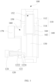
- FIGS. 1-12 for describing an aerosol generation device 100 according to some embodiments of the application.
- an embodiment of the application provides an aerosol generation device 100, which comprises: an enclosure 110, a resonance chamber, a microwave assembly 120, a resonance pillar 130, and probes 140.
- the enclosure 110, the resonance chamber is arranged in the enclosure 110, and the resonance chamber is configured to accommodate therein an aerosol generation substance;
- the aerosol generation device 100 provided in the application comprises: the enclosure 110, the resonance chamber, the microwave assembly 120, the resonance pillar 130, and the probes 140.
- the resonance chamber is arranged in the enclosure 110.
- the microwave assembly 120 is mounted on the enclosure 110, and the microwave assembly 120 is operable to feed the microwaves into the resonance chamber.
- the resonance pillar 130 is disposed in an interior of the resonance chamber, and the resonance pillar 130 has a diameter that is less than an inside diameter of the resonance chamber, and a gap is formed between the external wall of the resonance chamber and the internal wall the resonance chamber.
- the microwaves fed into the interior of the resonance chamber by the microwave assembly 120 transmits along the resonance pillar 130.
- the first end of the resonance pillar 130 is connected to the bottom wall of the resonance chamber, and the second end of the resonance pillar 130 faces the opening of the resonance chamber, so that the microwaves so fed can transmit in a direction from the first end of the resonance pillar 130 toward the second end.
- the aerosol generation substance is inserted from the opening of the resonance chamber into the interior of the resonance chamber, and the aerosol generation substance is set at a location of the resonance chamber that is adjacent to the opening.
- the microwaves transmitting through the resonance pillar 130 act on the aerosol generation substance to have the aerosol generation substance heated to atomize.
- the microwaves transmitting through the resonance pillar 130 to the aerosol generation substance act on an end of the aerosol generation substance.
- Plural probes 140 are arranged on the resonance pillar 130, and the plural probes 140 are distributed on a sidewall of the resonance pillar 130 at intervals.
- the aerosol generation substance is located among the plural probes 140.
- the plural probes 140 are arranged to be distributed around the circumferential wall of the aerosol generation device 100 such that the probes 140 may further transmit the microwaves that transmit through the resonance pillar 130, and the plural probes 140 transmit the microwaves to circumferential wall locations of the aerosol generation substance, so that during a process of operation of the aerosol generation device 100, the microwaves transmit through the probes 140 to a circumference of the aerosol generation substance to heat the aerosol generation substance from the circumference thereof, thereby reducing the distance that heat needs to travel inside the aerosol generation substance, and enhancing uniformity of heating to the aerosol generation substance to avoid incomplete heating of the aerosol generation substance and increase the utilization efficiency of the aerosol generation substance.
- the aerosol generation substance is arranged in the form of a bar, and the microwaves are acting on an end of the aerosol generation substance, and heat is conducted from the heated end of the aerosol generation substance toward an opposite end, so that the aerosol generation substance is heated in an incomplete way, and there occurs a problem that atomization is not done completely.
- the embodiment of the application provides the probes 140 arranged to transmit the microwaves to the circumference of the aerosol generation substance, so that the aerosol generation substance can be heated in a more complete way.
- the microwaves are transmitted through the resonance pillar 130 and the probes 140 to the aerosol generation substance, to allow the microwaves to act on the aerosol generation substance.
- the aerosol generation substance absorbs the microwaves, and polar molecules contained in the aerosol generation substance become fast oscillating to convert into thermal energy to thereby heat and atomize the aerosol generation substance.
- a material of the resonance pillar 130 is a metallic material.
- the resonance pillar 130 is made of an elemental metal, such as iron, copper, and aluminum, or the resonance pillar 130 is made of an alloy of iron, copper, and aluminum.
- the aerosol generation device 100 may further comprise the following additional features: In any one of the above embodiments, around the circumferential wall of the resonance pillar 130, the at least two probes 140 are uniformly arranged on the circumferential wall of the resonance pillar 130.
- the number of the probes 140 is plural, and the plural probes 140 are arranged on the circumferential wall of the resonance pillar 130, and the plural probes 140 surround and define a receiving space.
- the aerosol generation substance is inserted into the resonance chamber, and the aerosol generation substance is located in the receiving space.
- the plural probes 140 are uniformly arranged on the circumferential wall of the resonance pillar 130, and the plural probes 140 are extended in a direction toward the opening of the resonance chamber, so that the probes 140 are distributed on the circumference of the aerosol generation substance that is inserted into the resonance chamber, to thereby realize that the microwaves act in plural directions on the aerosol generation substance, and locations of action of the microwaves are more uniformly set and thus, uniformity of heating on the aerosol generation substance is enhanced, making the aerosol generation substance more completely atomized and increasing the utilization efficiency of the aerosol generation substance.
- a circumferential wall of the aerosol generation substance is in contact with the plural probes 140, and the microwaves outputted from the plural probes 140 directly act on the circumferential wall of the aerosol generation substance.
- the microwaves outputted from the plural probes 140 directly act on the circumferential wall of the aerosol generation substance.
- the number of the probes 140 can be selected as two, three, four, five, or six.
- the number of the probes 140 is set to be N, and an included angle between two adjacent probes 140 is equal to 360°/N.
- the probes 140 comprise: a connecting portion 142 and an extending portion 144.
- the connecting portion 142 is connected to the circumferential wall of the resonance pillar 130; and a first end of the extending portion 144 is connected to the connecting portion 142, and a second end of the extending portion 144 is extended in a direction toward the opening of the resonance chamber.
- the probe 140 comprises the connecting portion 142 and the extending portion 144.
- the probe 140 is mounted to the circumferential wall of the resonance pillar 130 by the connecting portion 142.
- the extending portion 144 can further transmit the microwaves that transmit through the resonance pillar 130.
- the extending direction of the extending portion 144 is set in a direction toward the opening of the resonance chamber, so as to have the extending portion 144 located on the circumference of the aerosol generation substance to thereby have the circumference of the aerosol generation substance uniformly heated.
- the extending portions 144 of the plural probes 140 are all extended in a direction toward the opening of the atomization chamber 152.
- the length of the extending portions 144 of the plural probes 140 is correspondingly set according to a size of the aerosol generation substance. For example, if the length of the plural probes 140 is set to be relatively great and ends of the plural probes 140 are set at a location that is close to an aerosol outputting portion of the aerosol generation substance, then the microwaves transmitting through the probes 140 may act on the aerosol generation substance closed to the aerosol outputting portion, so as to achieve an effect of fast releasing aerosol in a process of use of the aerosol generation device 100, and reducing a time interval of preheating the aerosol generation substance.
- an included angle between the connecting portion 142 and the extending portion 144 is in a range from 80° to 100°.
- setting the included angle between the connecting portion 142 and the extending portion 144 to be from 80° to 100° could ensure that the extending portion 144 is arranged in a manner of relatively parallel to the sidewall of the aerosol generation substance, making a distance between the aerosol generation substance and the extending portion 144 relatively short and thus increasing the utilization efficiency of the microwaves transmitting through the probes 140 to the aerosol generation substance.
- the connecting portion 142 is arranged perpendicular to the circumferential wall of the resonance pillar 130, and the extending portion 144 is arranged parallel with the circumferential wall of the resonance pillar 130, so that the included angle between the connecting portion 142 and the extending portion 144 is equal to 90°.
- the extending portions 144 of the plural probes 140 are arranged parallel with the circumferential wall of the resonance pillar 130, and this ensures that the extending portions 144 of the plural probes 140 are of the same distance from the circumferential wall of the aerosol generation substance to thereby further ensure the uniformity of microwave atomization of the aerosol generation substance induced by the microwaves transmitting through the plural probes 140.
- At least two of the connecting portions 142 are of the same size; and/or at least two of the extending portions 144 are of the same size.
- At least two of the connecting portions 142 are of the same size, which ensures that the distance of the extending portion 144 connected to each of the connecting portions 142 from the resonance pillar 130 is of the same size. Due to the resonance pillar 130 and the aerosol generation substance arranged coaxial with each other, this ensures that the extending portions 144 of the plural probes 140 are of the same distance from the aerosol generation substance to thereby further ensure the uniformity of microwave atomization of the aerosol generation substance induced by the microwaves transmitting through the plural probes 140.
- the sizes of the extending portions 144 of the plural probes 140 are the same size, it is possible to ensure that ends of the extending portions 144 of the plural probes 140 are all located on a same cross section of the aerosol generation substance so as to ensure the uniformity of the microwaves outputted therefrom.
- the microwave atomization device further comprises a holder 150 and an atomization chamber 152.
- the microwave atomization device further comprises the holder 150 and the atomization chamber 152.
- the holder 150 is arranged in the resonance chamber, and an interior of the holder 150 is provided with the atomization chamber 152.
- An opening is formed in an end of the holder 150, and the opening is in communication with the atomization chamber 152.
- the aerosol generation substance is inserted through the opening into the interior of the holder 150.
- the holder 150 functions to fix the aerosol generation substance in position. During a process of heating atomization, the aerosol generation substance generates solid or liquid wastes.
- the plural probes 140 are circumferentially distributed along the external wall of the holder 150, so that the microwaves transmitting through the probes 140 may directly act on the aerosol generation substance inside the atomization chamber 152 of the holder 150.
- a material of the holder 150 is a low dielectric loss material, such as: microwave-transparent ceramics, glass, and aluminum oxide and son on.
- a center axis of the resonance pillar 130 is coincident with a center axis of the atomization chamber 152.
- the resonance pillar 130 and the atomization chamber 152 are both of a regular shape.
- the resonance pillar 130 and the atomization chamber 152 are both cylindrical, and the center line of the resonance pillar 130 is coincident with the center line of the atomization chamber 152, meaning the axis of the resonance pillar 130 is coincident with the axis of the atomization chamber 152.
- the centers of the resonance pillar 130 and the aerosol generation substance coincide with each other, and this allows more of the microwaves transmitting through the resonance pillar 130 to act on the aerosol generation substance.
- the aerosol generation substance can be heated in a relatively short time period, so as to help achieve instantaneous heating.
- the holder 150 and the enclosure 110 are detachably connected with each other.
- the holder 150 by arranging the holder 150 to be detachably connected with the enclosure 110, users can individually detach the holder 150 for cleansing. To cleanse off the wastes generated during an atomization process of the aerosol generation substance, it only needs to cleanse the holder 150 that receives and holds the aerosol generation substance, and the electronic components of the aerosol generation device 100 affected in a cleansing operation can be prevented.
- the second end of the resonance pillar 130 and the holder 150 abut on each other.
- the second end of the resonance pillar 130 and the holder 150 abut on each other, so that the distance between the aerosol generation substance and the resonance pillar 130 is the thickness of a bottom wall of the holder 150.
- Arranging the resonance pillar 130 and the holder 150 to abut on each other could reduce, as much as possible, the spacing distance between the resonance pillar 130 and the aerosol generation substance, and an amount of deterioration of the microwaves are made small in the transmission of the microwaves through the resonance pillar 130.
- the microwaves may easily fast deteriorate when transmitting in a gap between the aerosol generation substance and the resonance pillar 130, so that reducing the spacing distance between the resonance pillar 130 and the aerosol generation substance as much as possible could reduce the amount of deterioration of the microwaves as much as possible to thereby allowing a relatively large amount of the microwaves to act on the aerosol generation substance to increase the heating rate of the aerosol generation substance.
- a cross-sectional area of the resonance pillar 130 is smaller than or equal to a cross-sectional area of the holder 150.
- a sideway contour edge of the resonance pillar 130 does not extend beyond a sideway contour edge of the holder 150, and consequently, a projection that the resonance pillar 130 casts on the bottom wall of the resonance chamber falls within a range of a projection that the holder 150 casts on the bottom wall of the resonance chamber, implying the holder 150 is thicker than the resonance pillar 130. This allows a majority of the microwaves that transmit through the resonance pillar 130 to directly act on the aerosol generation substance.
- the aerosol generation substance With the microwaves directly acting on the aerosol generation substance in a condition of being not deteriorated or having a relatively small amount of deterioration, the aerosol generation substance can be heated in a relatively short period of time, thereby increasing the heating rate of the aerosol generation substance and helping achieve instantaneous heating.
- the enclosure 110 comprises a first casing 112 and a second casing 114.
- the resonance pillar 130 is arranged in the first casing 112, and the second casing 114 is detachably connected with the first casing 112.
- the enclosure 110 comprises the first casing 112 and the second casing 114 that are detachably connected.
- the resonance pillar 130 is connected to a bottom wall of an internal-cavity of the first casing 112 to allow users to separately cleanse and maintain the first casing 112 and the second casing 114. And, when the first casing 112 or the second casing 114 is contaminated, it is possible to only replace the first casing 112 or the second casing 114 that has been contaminated, so as to reduce the daily maintenance expenditure of the aerosol generation device 100.
- the holder 150 and the second casing 114 are fixedly connected with each other, and when there is a need to cleanse the holder 150, the second casing 114 can be detached from the first casing 112, thereby achieving an effect of being easy to cleanse and maintain the first casing 112 and the holder 150.
- the aerosol generation device 100 comprises a through hole 160 and a pressure transducer 170.
- the through hole 160 is formed in the casing; and the pressure transducer 170 is arranged to the casing, the detecting end of the pressure transducer 170 being in communication with the resonance chamber using the through hole 160 to detect a gas pressure value of the interior of the resonance chamber.
- the aerosol generation device 100 further comprises the through hole 160, which is formed in the casing, and the pressure transducer 170, which is arranged to correspond to the through hole 160.
- the pressure transducer 170 is operable to detect, through the through hole 160 a gas pressure value of the interior of the resonance chamber. Since during a process of vaping by users, the gas pressure value of the interior of the resonance chamber may vary, and applying the pressure transducer 170 to detect the gas pressure value enables inspection of whether or not the aerosol generation device 100 is in a vaping condition. Further, based on the vaping condition of the aerosol generation device 100, control can be implemented on the operation of the microwave assembly 120.
- the microwave assembly 120 When the users stop vaping, it is possible to timely control the microwave assembly 120 to shut down the operation, so as to avoid wastage of electrical energy and the aerosol generation substance, and realizing effect of preheating the aerosol generation substance for the aerosol generation device 100 in a non-vaping condition and quickly heating the aerosol generation substance to an atomization temperature for the vaping condition, to thereby reduce energy consumption of energy and also enhance the atomization efficiency of the aerosol generation substance, and also improving the atomization of the aerosol generation substance to thus improve users' experience of use.
- the microwave assembly 120 comprises a microwave lead-in section 122 and a microwave emission source 124.
- the microwave lead-in section 122 is arranged on a sidewall of the enclosure 110; and the microwave emission source 124 is connected to the microwave lead-in section 122, the microwaves outputted from the microwave emission source 124 fed through the microwave lead-in section 122 into the interior of the resonance chamber, to allow the microwaves to transmit in a direction from the first end of the resonance pillar 130 toward the second end of the resonance pillar 130.
- the microwave emission source 124 is operable to generate the microwaves, and the microwaves are transmitted through the microwave lead-in section 122 into the interior of the resonance chamber.
- an entry site of the microwaves in the resonance chamber can be varied, so as to avoid components inside the resonance chamber and also to ensure stable transmission of the microwaves from the first end of the resonance pillar 130 toward the second end of the resonance pillar 130.
- the microwave lead-in section 122 comprises a first lead-in part 1222 and a second lead-in part 1224.
- the first lead-in part 1222 is arranged on the sidewall of the enclosure 110; and a first end of the second lead-in part 1224 is connected to the first lead-in part 1222, the second lead-in part 1224 located inside the resonance chamber, a second end of the second lead-in part 1224 facing the chamber bottom wall of the resonance chamber.
- the microwave lead-in section 122 is made up of two parts, which are the first lead-in part 1222 and the second lead-in part 1224.
- the first lead-in part 1222 is mounted in the sidewall of the casing, and the first lead-in part 1222 is connected to the microwave emission source 124, so that the microwaves generated from the microwave emission source 124 are fed through the first lead-in part 1222 into the interior of the resonance chamber.
- the second lead-in part 1224 changes a direction of transmission of the microwave. Since the second lead-in part 1224 faces the bottom wall of the resonance chamber, the microwaves are transmitted toward the bottom wall of the resonance chamber. Microwaves at the bottom wall of the resonance chamber are transmitted through the resonance pillar 130 toward the aerosol generation substance.
- the second lead-in part 1224 arranged to face the bottom wall of the resonance chamber ensures that the transmission of the microwaves starts from the first end of the resonance pillar 130 so as to avoid loss of the microwaves.
- the microwave lead-in section 122 comprises a third lead-in part 1226 and a fourth lead-in section 1228.
- the third lead-in part 1226 is arranged in the sidewall of the enclosure 110; and the first end of the fourth lead-in section 1228 is connected to the third lead-in part 1226, the fourth lead-in section 1228 located inside the resonance chamber, the second end of the fourth lead-in section 1228 facing the resonance pillar 130.
- the microwave lead-in section 122 is made up of two parts, which are the first lead-in part 1222 and the second lead-in part 1224.
- the first lead-in part 1222 is mounted on the sidewall of the casing, and the first lead-in part 1222 is connected to the microwave emission source 124, so that the microwaves generated from the microwave emission source 124 are fed through the first lead-in part 1222 into the interior of the resonance chamber.
- the second lead-in part 1224 faces the resonance pillar 130, meaning the second lead-in part 1224 is parallel with the bottom wall of the resonance chamber, so that the second lead-in part 1224 has a shorter length and thus is capable of quickly transmitting the microwaves to the resonance pillar 130, avoiding loss of the microwaves.
- connecting can be fixedly connecting among multiple objects, and can also be detachably connecting among multiple objects, or integrally connected; and can be directly connecting among multiple objects, and can also be indirectly connecting by means of an intermediate medium among multiple objects.
- connecting can be fixedly connecting among multiple objects, and can also be detachably connecting among multiple objects, or integrally connected; and can be directly connecting among multiple objects, and can also be indirectly connecting by means of an intermediate medium among multiple objects.
Landscapes
- Physics & Mathematics (AREA)
- Electromagnetism (AREA)
- Constitution Of High-Frequency Heating (AREA)
Abstract
Description
- The present invention relates to the technical field of electronic atomization, and more particularly to an aerosol generation device.
- A heat-not-burning (HNB) device is a kind of combination equipment including a heating device combined with an aerosol generation substance (such as a product of processed plant leaves). An external heating device heats, at a high temperature, the aerosol generation substance to a temperature that can generate an aerosol, but is not sufficient to cause burning, so that, without being caused to burn, the aerosol generation substance generates an aerosol desired by a user.
- The heat-not-burning devices that are currently available in the market generally adopts resistor heating means, namely a centered heating plate or a heating pin penetrates, at a center location of the aerosol generation substance, into the interior of the aerosol generation substance to proceed with heating. Such a utensil takes a long time to wait for preheating before use, making it impossible to freely start or stop vaping, and the aerosol generation substance cannot be uniformly carbonized, leading to insufficient baking of the aerosol generation substance and low efficiency of utilization. Secondly, the heating plate of the HNB utensil may easily cause generation of contaminants, which are hard to cleanse, in an aerosol generation substance extractor and a heating plate holder, and a portion of the aerosol generation substance that is in contact with the heating body may get locally excessively high temperature, causing partial decomposition and releasing substances that are harmful to human bodies. Thus, the resistor heating means is gradually replaced by microwave heating technology, which becomes a new solution of heating. The microwave heating technology has advantages in respect of high efficiency, timeliness, optionality, and non-delay heating, and is only effective of heating for specific substances having certain dielectric properties. Advantages of microwave heating based atomization include: (a) instantaneous vaping or stopping being achievable as the microwave heating is radiation based heating, rather than heat conduction; (b) there being no plate breaking or heating plate cleansing issues as no heating plate is involved; and (c) the utilization efficiency of the aerosol generation substance being high and mouthfeel being consistent, and the mouthfeel being much closer to cigarettes.
- In the prior art, microwaves are often fed from one end into a resonance chamber, and this makes the heating to the aerosol generation substance inside the resonance chamber ununiform.
- The application aims to resolve one of the technical issues that the prior art or the related art is suffering.
- In view of this, the embodiment of the application provides an aerosol generation device which comprises an enclosure, a resonance chamber arranged in the enclosure, the resonance chamber being capable of receiving and holding therein an aerosol generation substance; a microwave assembly, which is arranged on the enclosure, the microwave assembly being operable to feed microwaves to the interior of the resonance chamber; a resonance pillar, a first end of the resonance pillar connected to the chamber bottom wall of the resonance chamber, a second end of the resonance pillar facing the opening of the resonance chamber; probes, the number of the probes being at least two, the at least two probes arranged at intervals on the resonance pillar, the aerosol generation substance located between the at least two probes.
- The aerosol generation device provided in the application comprises the enclosure, the resonance chamber, the microwave assembly, the resonance pillar, and the probes. The resonance chamber is arranged in the enclosure. The microwave assembly is mounted on the enclosure, and the microwave assembly is operable to feed the microwaves into the resonance chamber. The resonance pillar is disposed inside the resonance chamber, and the resonance pillar has a diameter that is less than an inside diameter of the resonance chamber, and a gap is formed between the external wall of the resonance chamber and the internal wall the resonance chamber. The microwaves fed into the interior of the resonance chamber by the microwave assembly transmits along the resonance pillar. The first end of the resonance pillar is connected to the bottom wall of the resonance chamber, and the second end of the resonance pillar faces the opening of the resonance chamber, so that the microwaves so fed can transmit in a direction from the first end of the resonance pillar toward the second end. In a process of use of the aerosol generation device, the aerosol generation substance is inserted from the opening of the resonance chamber into the interior of the resonance chamber, and the aerosol generation substance is set at a location of the resonance chamber that is adjacent to the opening. The microwaves transmitting through the resonance pillar act on the aerosol generation substance to have the aerosol generation substance heated to atomize. The microwaves transmitting through the resonance pillar to the aerosol generation substance act on an end of the aerosol generation substance. Plural probes are arranged on the resonance pillar, and the plural probes are distributed on the sidewall of the resonance pillar. The aerosol generation substance is located among the plural probes. The plural probes are arranged to distributed around the circumferential wall of the aerosol generation device. The probes may further transmit the microwaves that transmits through the resonance pillar, and the plural probes transmit the microwaves to circumferential wall locations of the aerosol generation substance, so that during a process of operation of the aerosol generation device, the microwaves transmits through the probes to a circumference of the aerosol generation substance to heat the aerosol generation substance from the circumference thereof, thereby reducing the distance that heat needs to travel inside the aerosol generation substance, and enhancing uniformity of heating to the aerosol generation substance to avoid incomplete heating of the aerosol generation substance and increase the utilization efficiency of the aerosol generation substance.
- It is appreciated that, in the related art, the aerosol generation substance is arranged in the form of a bar, and the microwaves are acting on an end of the aerosol generation substance, and heat is conducted from the heated end of the aerosol generation substance toward an opposite end, so that the aerosol generation substance is heated in an incomplete way, and there occurs a problem that atomization is not done completely. The embodiment of the application provides the probes arranged to transmit the microwaves to the circumference of the aerosol generation substance, so that the aerosol generation substance can be heated in a more complete way.
- It is noted that the microwaves are transmitted through the resonance pillar and the probes to the aerosol generation substance, to allow the microwaves to act on the aerosol generation substance. The aerosol generation substance absorbs the microwaves, and polar molecules contained in the aerosol generation substance become fast oscillating to convert into thermal energy to thereby heat and atomize the aerosol generation substance.
- In an illustrative example, a material of the resonance pillar is a metallic material. For example, the resonance pillar is made of an elemental metal, such as iron, copper, and aluminum, or the resonance pillar is made of an alloy of iron, copper, and aluminum.
- Further, the aerosol generation device according to the above technical solution provided in the application may further comprise the following additional features:
In a feasible embodiment, around the circumferential wall of the resonance pillar, the at least two probes are uniformly arranged on the circumferential wall of the resonance pillar. - In the embodiment, the number of the probes is plural, and the plural probes are arranged on the circumferential wall of the resonance pillar, and the plural probes surround and define a receiving space. The aerosol generation substance is inserted into the resonance chamber, and the aerosol generation substance is located in the receiving space. The plural probes are uniformly arranged on the circumferential wall of the resonance pillar, and the plural probes are extended in a direction toward the opening of the resonance chamber, so that the probes are distributed on the circumference of the aerosol generation substance that is inserted into the resonance chamber, to thereby realize that the microwaves act on the aerosol generation substance in plural directions, and locations of action of the microwaves are more uniformly set and thus, uniformity of heating on the aerosol generation substance is enhanced, making the aerosol generation substance more completely atomized and increasing the utilization efficiency of the aerosol generation substance.
- In some embodiments, the circumferential wall of the aerosol generation substance is in contact with the plural probes, and the microwaves outputted from the plural probes directly act on the circumferential wall of the aerosol generation substance. In other words, after the circumference of the aerosol generation substance is heated, heat spreads from the circumference of the aerosol generation substance into the interior of the aerosol generation substance. Due to the probes uniformly distributed on the circumference of the aerosol generation substance, heating to the aerosol generation substance is made more uniformly.
- In some embodiments, the number of the probes can be selected as two, three, four, five, or six.
- In these embodiments, the number of the probes is set to be N, and an included angle between two adjacent probes is equal to 360°/N.
- In a feasible embodiment, the probes comprise a connecting portion which is connected to the circumferential wall of the resonance pillar; and an extending portion, a first end of the extending portion connected to the connecting portion, a second end of the extending portion extended in a direction toward the opening of the resonance chamber.
- In the embodiment, the probe comprises the connecting portion and the extending portion. The probe is mounted to the circumferential wall of the resonance pillar by the connecting portion. The extending portion functions to further transmit the microwaves that transmit through the resonance pillar. An extending direction of the extending portion is set in a direction toward the opening of the resonance chamber, so as to have the extending portion located on the circumference of the aerosol generation substance to thereby have the aerosol generation substance the circumference uniformly heated.
- It is noted that the extending portions of the plural probes are all extended in a direction toward the opening of the atomization chamber. The length of the extending portions of the plural probes is correspondingly set according to a size of the aerosol generation substance. For example, if the length of the plural probes is set to be relatively great and ends of the plural probes are set at a location that is close to an aerosol outputting portion of the aerosol generation substance, then the microwaves transmitting through the probes may act on the aerosol generation substance closed to the aerosol outputting portion, so as to achieve an effect of fast releasing aerosol in a process of use of the aerosol generation device, and reducing a time interval of preheating the aerosol generation substance.
- In a feasible embodiment, an included angle between the connecting portion and the extending portion is in a range from 80° to 100°.
- In the embodiment, setting the included angle between the connecting portion and the extending portion to be from 80° to 100° could ensure that the extending portion is arranged in a manner of relatively parallel to the sidewall of the aerosol generation substance, making a distance between the aerosol generation substance and the extending portion relatively short and thus increasing the utilization efficiency of the microwaves transmitting through the probes to the aerosol generation substance.
- In some embodiments, the connecting portion is arranged perpendicular to the circumferential wall of the resonance pillar, and the extending portion is arranged parallel with the circumferential wall of the resonance pillar, so that the included angle between the connecting portion and the extending portion is equal to 90°.
- In these embodiments, the extending portions of the plural probes are arranged parallel with the circumferential wall of the resonance pillar, and this ensures that the extending portions of the plural probes are of the same distance from the circumferential wall of the aerosol generation substance to thereby further ensure the uniformity of microwave atomization of the aerosol generation substance induced by the microwaves transmitting through the plural probes.
- In a feasible embodiment, at least two of the connecting portions are of the same size; and/or at least two of the extending portions are of the same size.
- In the embodiment, at least two of the connecting portions are of the same size, which ensures that the distance of the extending portion connected to each of the connecting portions from the resonance pillar is of the same size. Due to the resonance pillar and the aerosol generation substance arranged coaxial with each other, this ensures that the extending portions of the plural probes are of the same distance from the aerosol generation substance to thereby further ensure the uniformity of microwave atomization of the aerosol generation substance induced by the microwaves transmitting through the plural probes. By setting the sizes of the extending portions of the plural probes to be the same size, it is possible to ensure that ends of the extending portions of the plural probes are all located on a same cross section of the aerosol generation substance so as to ensure the uniformity of the microwaves outputted therefrom.
- In a feasible embodiment, the microwave atomization device further comprises a holder, which is arranged in the resonance chamber, the holder and the resonance pillar arranged to face each other, the at least two probes circumferentially distributed around the circumferential wall of the holder; and an atomization chamber, which is arranged in the holder, the atomization chamber configured for receiving and holding the aerosol generation substance.
- In the embodiment, the microwave atomization device further comprises the holder and the atomization chamber. The holder is arranged in the resonance chamber, and the atomization chamber is arranged inside the holder. An opening is formed in an end of the holder, and the opening is in communication with the atomization chamber. The aerosol generation substance is inserted through the opening into the interior of the holder. The holder functions to fix the aerosol generation substance in position. During a process of heating atomization, the aerosol generation substance generates solid or liquid wastes. By placing the aerosol generation substance inside the atomization chamber of the holder to atomize therein, it is possible to ensure the wastes do not enter the resonance chamber, ensuring that the resonance chamber is not contaminated. The plural probes are circumferentially distributed around the external wall of the holder, so that the microwaves transmitting through the probes may directly act on the aerosol generation substance inside the atomization chamber of the holder.
- It is appreciated that a material of the holder is a low dielectric loss material, such as: microwave-transparent ceramics, glass, and aluminum oxide.
- In a feasible arrangement, a center axis of the resonance pillar is coincident with a center axis of the atomization chamber.
- In the arrangement, the resonance pillar and the atomization chamber are both of a regular shape. As an example, the resonance pillar and the atomization chamber are both cylindrical, and the center line of the resonance pillar is coincident with the center line of the atomization chamber, meaning the axis of the resonance pillar is coincident with the axis of the atomization chamber. By having the centers of the resonance pillar and the atomization chamber coincident with each other, the centers of the resonance pillar and the aerosol generation substance coincide, and this allows more of the microwaves transmitting through the resonance pillar to be acting on the aerosol generation substance. By concentrating the microwaves to act on the aerosol generation substance, the aerosol generation substance can be heated in a relatively short time period, so as to help achieve instantaneous heating.
- In a feasible embodiment, the holder and the enclosure are detachably connected.
- In the embodiment, by arranging the holder to be detachably connected with the enclosure, users can individually remove the holder for cleansing. To cleanse off the wastes generated during an atomization process of the aerosol generation substance, it only needs to cleanse the holder that receives and holds the aerosol generation substance, and the electronic components of the aerosol generation device affected in a cleansing operation can be prevented.
- In a feasible arrangement, the second end of the resonance pillar and the holder abut on each other.
- In the arrangement, the second end of the resonance pillar and the holder abut on each other, so that the distance between the aerosol generation substance and the resonance pillar is the thickness of a bottom wall of the holder. Arranging the resonance pillar and the holder to abut on each other could reduce, as much as possible, the spacing distance between the resonance pillar and the aerosol generation substance, and an amount of deterioration of the microwaves are made small in the transmission of the microwave through the resonance pillar. The microwave may easily fast deteriorate when transmitting in a gap between the aerosol generation substance and the resonance pillar, so that reducing the spacing distance between the resonance pillar and the aerosol generation substance as much as possible could reduce the amount of deterioration of the microwaves as much as possible to thereby allowing a relatively large amount of the microwaves to act on the aerosol generation substance to increase the heating rate of the aerosol generation substance.
- In a feasible arrangement, by taking a cross-section of the resonance pillar and the holder in the direction perpendicular to a center line of the resonance pillar, a cross-sectional area of the resonance pillar is smaller than or equal to a cross-sectional area of the holder.
- In the arrangement, a sideway contour edge of the resonance pillar does not extend beyond a sideway contour edge of the holder, and consequently, a projection that the resonance pillar casts on the bottom wall of the resonance chamber falls within a range of a projection that the holder casts on the bottom wall of the resonance chamber, implying the holder is thicker than the resonance pillar. This allows a majority of the microwaves that transmit through the resonance pillar to directly act on the aerosol generation substance. With the microwaves directly acting on the aerosol generation substance in a condition of being not deteriorated or having a relatively small amount of deterioration, the aerosol generation substance can be heated in a relatively short period of time, thereby increasing the heating rate of the aerosol generation substance and helping achieve instantaneous heating.
- In a feasible arrangement, the enclosure comprises a first casing, the resonance pillar arranged in the first casing; and a second casing, which is detachably connected with the first casing.
- In the arrangement, the enclosure comprises the first casing and the second casing that are detachably connected. The resonance pillar is connected to the bottom wall of an internal-cavity the first casing to allow users to separately cleanse and maintain the first casing and the second casing. And, when the first casing or the second casing is contaminated, it is possible to only replace the first casing or the second casing that has been contaminated, so as to reduce the daily maintenance expenditure of the aerosol generation device.
- In some embodiments, the holder and the second casing are fixedly connected with each other, and when it is necessary to cleanse the holder, the second casing can be removed from the first casing, thereby achieving an effect of being easy to cleanse and maintain the first casing and the holder.
- In a feasible arrangement, the aerosol generation device comprises: a through hole, which is formed in the casing; and a pressure transducer, which is arranged in the casing, a detecting end of the pressure transducer being in communication with the resonance chamber using the through hole to detect a gas pressure value of the interior of the resonance chamber.
- In the arrangement, the aerosol generation device further comprises the through hole, which is formed in the casing, and the pressure transducer, which is arranged to correspond to the through hole. The pressure transducer is operable to detect, through the through hole a gas pressure value of the interior of the resonance chamber. Since during a process of vaping by users, the gas pressure value of the interior of the resonance chamber may vary, and applying the pressure transducer to detect the gas pressure values enables inspection of whether or not the aerosol generation device is in a vaping condition. Further, based on the vaping condition of the aerosol generation device, control can be implemented on the operation of the microwave assembly. When the users stop vaping, it is possible to timely control the microwave assembly to shut down the operation, so as to avoid wastage of electrical energy and the aerosol generation substance, and realizing effect of preheating the aerosol generation substance for the aerosol generation device in a non-vaping condition and quickly heating the aerosol generation substance to an atomization temperature for the vaping condition, to thereby reduce energy consumption and also enhance the atomization efficiency of the aerosol generation substance, and also improving the atomization of the aerosol generation substance to thus improve users' experience of use.
- In a feasible arrangement, the microwave assembly comprises a microwave lead-in section, which is arranged on a sidewall of the enclosure; and a microwave emission source, which is connected to the microwave lead-in section, the microwaves outputted from the microwave emission source fed through the microwave lead-in section into the interior of the resonance chamber, to allow the microwaves to transmit in a direction from the first end of the resonance pillar toward the second end of the resonance pillar.
- In the arrangement, the microwave emission source is operable to generate the microwaves, and the microwaves are transmitted through the microwave lead-in section into the interior of the resonance chamber. With the arrangement of the microwave lead-in section, an entry site of the microwaves in the resonance chamber can be varied, so as to avoid components inside the resonance chamber and also to ensure stable transmission of the microwaves from the first end of the resonance pillar toward the second end of the resonance pillar.
- In a feasible arrangement, the microwave lead-in section comprises a first lead-in part, which is arranged on the sidewall of the enclosure; and a second lead-in part, a first end of the second lead-in part connected to the first lead-in part, the second lead-in part located inside the resonance chamber, a second end of the second lead-in part facing the chamber bottom wall of the resonance chamber.
- In the arrangement, the microwave lead-in section is made up of two parts, which are the first lead-in part and the second lead-in part. The first lead-in part is mounted in the sidewall of the casing, and the first lead-in part is connected to the microwave emission source, so that the microwaves generated from the microwave emission source is fed through the first lead-in part into the interior of the resonance chamber. The second lead-in part changes a direction of transmission of the microwaves. Since the second lead-in part faces the bottom wall of the resonance chamber, the microwaves are transmitted toward the bottom wall of the resonance chamber. Microwaves at the bottom wall of the resonance chamber are transmitted through the resonance pillar toward the aerosol generation substance. The second lead-in part arranged to face the bottom wall of the resonance chamber ensures that the transmission of the microwaves through resonance pillar starts from the first end of the resonance pillar so as to avoid loss of the microwaves.
- In a feasible arrangement, the microwave lead-in section comprises a third lead-in part, which is arranged in the sidewall of the enclosure; and a fourth lead-in section, a first end of the fourth lead-in section connected to the third lead-in part, the fourth lead-in section located inside the resonance chamber, a second end of the fourth lead-in section facing the resonance pillar.
- In the arrangement, the microwave lead-in section is made up of two parts, which are the first lead-in part and the second lead-in part. The first lead-in part is mounted to the sidewall of the casing, and the first lead-in part is connected to the microwave emission source, so that the microwaves generated from the microwave emission source are fed through the first lead-in part into the interior of the resonance chamber. The second lead-in part faces the resonance pillar, meaning the second lead-in part is parallel with the bottom wall of the resonance chamber, so that the second lead-in part has a shorter length and thus is capable of quickly transmitting the microwaves to the resonance pillar, avoiding loss of the microwaves.
- Additional aspects and advantages of the application will become obvious from the following section of description or can be appreciated through implementation of the application.
- The above and/or additional aspects and advantages of the application will become apparent and readily understandable from the following description of embodiments, with reference to the attached drawings, in which:
-
FIG. 1 illustrates a first one of schematic structure diagrams showing an aerosol generation device according to embodiments of the application; -
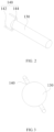
FIG. 2 illustrates a first one of schematic structure diagrams showing a resonance pillar and probes of the aerosol generation device according to the embodiments of the application; -
FIG. 3 illustrates a second one of schematic structure diagrams showing the resonance pillar and the probes of the aerosol generation device according to the embodiments of the application; -
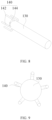
FIG. 4 illustrates a third one of schematic structure diagrams showing the resonance pillar and the probes of the aerosol generation device according to the embodiments of the application; -
FIG. 5 illustrates a fourth one of schematic structure diagrams showing the resonance pillar and the probes of the aerosol generation device according to the embodiments of the application; -
FIG. 6 illustrates a fifth one of schematic structure diagrams showing the resonance pillar and the probes of the aerosol generation device according to the embodiments of the application; -
FIG. 7 illustrates a sixth one of schematic structure diagrams showing the resonance pillar and the probes of the aerosol generation device according to the embodiments of the application; -
FIG. 8 illustrates a seventh one of schematic structure diagrams showing the resonance pillar and the probes of the aerosol generation device according to the embodiments of the application; -
FIG. 9 illustrates an eighth one of schematic structure diagrams showing the resonance pillar and the probes of the aerosol generation device according to the embodiments of the application; -
FIG. 10 illustrates a ninth one of schematic structure diagrams showing the resonance pillar and the probes of the aerosol generation device according to the embodiments of the application; -
FIG. 11 illustrates a tenth one of schematic structure diagrams showing the resonance pillar and the probes of the aerosol generation device according to the embodiments of the application; and -
FIG. 12 illustrates a second one of schematic structure diagrams showing the aerosol generation device according to the embodiments of the application. - wherein a corresponding relationship between the reference signs adopted in
FIGS. 1-12 and the parts is as follows: - 100 aerosol generation device; 110 enclosure; 112 first casing; 114 second casing; 120 microwave assembly; 122 microwave lead-in section; 1222 first lead-in part; 1224 second lead-in part; 1226 third lead-in part; 1228 fourth lead-in section; 124 microwave emission source; 130 resonance pillar; 140 probe; 142 connecting portion; 144 extending portion; 150 holder; 152 atomization chamber; 160 through hole; 170 pressure transducer.
- For better understanding of the above objectives, features, and advantages of the application, a detailed description of the application will be provided below with reference to the attached drawings and specific ways of embodiment. It is noted that without causing conflicts, embodiments of the application and features of the embodiments are combinable with each other.
- The description provided below gives an explanation to a lot of specifics and details for the purposes of better understanding of the application. However, the application can also be implemented by adopting other ways that are not described herein. Thus, the scope of protection that the application pursues is not limited to the specific embodiments disclosed below.
- In the following, reference is made to
FIGS. 1-12 for describing anaerosol generation device 100 according to some embodiments of the application. - As shown in
FIG. 1 , an embodiment of the application provides anaerosol generation device 100, which comprises: anenclosure 110, a resonance chamber, amicrowave assembly 120, aresonance pillar 130, and probes 140. - Wherein, the
enclosure 110, the resonance chamber is arranged in theenclosure 110, and the resonance chamber is configured to accommodate therein an aerosol generation substance; - the
microwave assembly 120 is arranged on theenclosure 110, themicrowave assembly 120 being operable to feed microwaves to the interior of the resonance chamber; - a first end of the
resonance pillar 130 is connected to the chamber bottom wall of the resonance chamber, and a second end of theresonance pillar 130 faces an opening of the resonance chamber; and - the number of the
probes 140 is at least two, and the at least twoprobes 140 are arranged, at intervals, on theresonance pillar 130, the aerosol generation substance located between the at least twoprobes 140. - The
aerosol generation device 100 provided in the application comprises: theenclosure 110, the resonance chamber, themicrowave assembly 120, theresonance pillar 130, and theprobes 140. The resonance chamber is arranged in theenclosure 110. Themicrowave assembly 120 is mounted on theenclosure 110, and themicrowave assembly 120 is operable to feed the microwaves into the resonance chamber. Theresonance pillar 130 is disposed in an interior of the resonance chamber, and theresonance pillar 130 has a diameter that is less than an inside diameter of the resonance chamber, and a gap is formed between the external wall of the resonance chamber and the internal wall the resonance chamber. The microwaves fed into the interior of the resonance chamber by themicrowave assembly 120 transmits along theresonance pillar 130. The first end of theresonance pillar 130 is connected to the bottom wall of the resonance chamber, and the second end of theresonance pillar 130 faces the opening of the resonance chamber, so that the microwaves so fed can transmit in a direction from the first end of theresonance pillar 130 toward the second end. In a process of use of theaerosol generation device 100, the aerosol generation substance is inserted from the opening of the resonance chamber into the interior of the resonance chamber, and the aerosol generation substance is set at a location of the resonance chamber that is adjacent to the opening. The microwaves transmitting through theresonance pillar 130 act on the aerosol generation substance to have the aerosol generation substance heated to atomize. The microwaves transmitting through theresonance pillar 130 to the aerosol generation substance act on an end of the aerosol generation substance.Plural probes 140 are arranged on theresonance pillar 130, and theplural probes 140 are distributed on a sidewall of theresonance pillar 130 at intervals. The aerosol generation substance is located among the plural probes 140. Theplural probes 140 are arranged to be distributed around the circumferential wall of theaerosol generation device 100 such that theprobes 140 may further transmit the microwaves that transmit through theresonance pillar 130, and theplural probes 140 transmit the microwaves to circumferential wall locations of the aerosol generation substance, so that during a process of operation of theaerosol generation device 100, the microwaves transmit through theprobes 140 to a circumference of the aerosol generation substance to heat the aerosol generation substance from the circumference thereof, thereby reducing the distance that heat needs to travel inside the aerosol generation substance, and enhancing uniformity of heating to the aerosol generation substance to avoid incomplete heating of the aerosol generation substance and increase the utilization efficiency of the aerosol generation substance. - It is appreciated that, in the related art, the aerosol generation substance is arranged in the form of a bar, and the microwaves are acting on an end of the aerosol generation substance, and heat is conducted from the heated end of the aerosol generation substance toward an opposite end, so that the aerosol generation substance is heated in an incomplete way, and there occurs a problem that atomization is not done completely. The embodiment of the application provides the
probes 140 arranged to transmit the microwaves to the circumference of the aerosol generation substance, so that the aerosol generation substance can be heated in a more complete way. - It is noted that the microwaves are transmitted through the
resonance pillar 130 and theprobes 140 to the aerosol generation substance, to allow the microwaves to act on the aerosol generation substance. The aerosol generation substance absorbs the microwaves, and polar molecules contained in the aerosol generation substance become fast oscillating to convert into thermal energy to thereby heat and atomize the aerosol generation substance. - In an illustrative example, a material of the
resonance pillar 130 is a metallic material. For example, theresonance pillar 130 is made of an elemental metal, such as iron, copper, and aluminum, or theresonance pillar 130 is made of an alloy of iron, copper, and aluminum. - Further, the
aerosol generation device 100 according to the above technical solution provided in the application may further comprise the following additional features:
In any one of the above embodiments, around the circumferential wall of theresonance pillar 130, the at least twoprobes 140 are uniformly arranged on the circumferential wall of theresonance pillar 130. - In the embodiment, the number of the
probes 140 is plural, and theplural probes 140 are arranged on the circumferential wall of theresonance pillar 130, and theplural probes 140 surround and define a receiving space. The aerosol generation substance is inserted into the resonance chamber, and the aerosol generation substance is located in the receiving space. Theplural probes 140 are uniformly arranged on the circumferential wall of theresonance pillar 130, and theplural probes 140 are extended in a direction toward the opening of the resonance chamber, so that theprobes 140 are distributed on the circumference of the aerosol generation substance that is inserted into the resonance chamber, to thereby realize that the microwaves act in plural directions on the aerosol generation substance, and locations of action of the microwaves are more uniformly set and thus, uniformity of heating on the aerosol generation substance is enhanced, making the aerosol generation substance more completely atomized and increasing the utilization efficiency of the aerosol generation substance. - In some embodiments, a circumferential wall of the aerosol generation substance is in contact with the
plural probes 140, and the microwaves outputted from theplural probes 140 directly act on the circumferential wall of the aerosol generation substance. In other words, after the circumference of the aerosol generation substance is heated, heat spreads from the circumference of the aerosol generation substance into the interior of the aerosol generation substance. Due to theprobes 140 uniformly distributed on the circumference of the aerosol generation substance, heating to the aerosol generation substance is made more uniformly. - As shown in
FIGS. 2, 3 ,4, 5 ,6, 7 ,8, 9 ,10, and 11 , in some embodiments, the number of theprobes 140 can be selected as two, three, four, five, or six. - In these embodiments, the number of the
probes 140 is set to be N, and an included angle between twoadjacent probes 140 is equal to 360°/N. - In any one of the above embodiments, the
probes 140 comprise: a connectingportion 142 and an extendingportion 144. - Wherein, the connecting
portion 142 is connected to the circumferential wall of theresonance pillar 130; and
a first end of the extendingportion 144 is connected to the connectingportion 142, and a second end of the extendingportion 144 is extended in a direction toward the opening of the resonance chamber. - In the embodiment, the
probe 140 comprises the connectingportion 142 and the extendingportion 144. Theprobe 140 is mounted to the circumferential wall of theresonance pillar 130 by the connectingportion 142. The extendingportion 144 can further transmit the microwaves that transmit through theresonance pillar 130. The extending direction of the extendingportion 144 is set in a direction toward the opening of the resonance chamber, so as to have the extendingportion 144 located on the circumference of the aerosol generation substance to thereby have the circumference of the aerosol generation substance uniformly heated. - It is noted that the extending
portions 144 of theplural probes 140 are all extended in a direction toward the opening of theatomization chamber 152. The length of the extendingportions 144 of theplural probes 140 is correspondingly set according to a size of the aerosol generation substance. For example, if the length of theplural probes 140 is set to be relatively great and ends of theplural probes 140 are set at a location that is close to an aerosol outputting portion of the aerosol generation substance, then the microwaves transmitting through theprobes 140 may act on the aerosol generation substance closed to the aerosol outputting portion, so as to achieve an effect of fast releasing aerosol in a process of use of theaerosol generation device 100, and reducing a time interval of preheating the aerosol generation substance. - In any one of the above embodiments, an included angle between the connecting
portion 142 and the extendingportion 144 is in a range from 80° to 100°. - In the embodiment, setting the included angle between the connecting
portion 142 and the extendingportion 144 to be from 80° to 100° could ensure that the extendingportion 144 is arranged in a manner of relatively parallel to the sidewall of the aerosol generation substance, making a distance between the aerosol generation substance and the extendingportion 144 relatively short and thus increasing the utilization efficiency of the microwaves transmitting through theprobes 140 to the aerosol generation substance. - In some embodiments, the connecting
portion 142 is arranged perpendicular to the circumferential wall of theresonance pillar 130, and the extendingportion 144 is arranged parallel with the circumferential wall of theresonance pillar 130, so that the included angle between the connectingportion 142 and the extendingportion 144 is equal to 90°. - In these embodiments, the extending
portions 144 of theplural probes 140 are arranged parallel with the circumferential wall of theresonance pillar 130, and this ensures that the extendingportions 144 of theplural probes 140 are of the same distance from the circumferential wall of the aerosol generation substance to thereby further ensure the uniformity of microwave atomization of the aerosol generation substance induced by the microwaves transmitting through the plural probes 140. - In any one of the above embodiments, at least two of the connecting
portions 142 are of the same size; and/or at least two of the extendingportions 144 are of the same size. - In the embodiment, at least two of the connecting
portions 142 are of the same size, which ensures that the distance of the extendingportion 144 connected to each of the connectingportions 142 from theresonance pillar 130 is of the same size. Due to theresonance pillar 130 and the aerosol generation substance arranged coaxial with each other, this ensures that the extendingportions 144 of theplural probes 140 are of the same distance from the aerosol generation substance to thereby further ensure the uniformity of microwave atomization of the aerosol generation substance induced by the microwaves transmitting through the plural probes 140. By setting the sizes of the extendingportions 144 of theplural probes 140 to be the same size, it is possible to ensure that ends of the extendingportions 144 of theplural probes 140 are all located on a same cross section of the aerosol generation substance so as to ensure the uniformity of the microwaves outputted therefrom. - As shown in
FIGS. 1 and12 , in any one of the above embodiments, the microwave atomization device further comprises aholder 150 and anatomization chamber 152. - wherein, the
holder 150 is arranged in the resonance chamber, theholder 150 and theresonance pillar 130 arranged to face each other, the at least twoprobes 140 circumferentially distributed around the circumferential wall of theholder 150; and - the
atomization chamber 152 arranged in theholder 150 and configured to receive and hold the aerosol generation substance. - In the embodiment, the microwave atomization device further comprises the
holder 150 and theatomization chamber 152. Theholder 150 is arranged in the resonance chamber, and an interior of theholder 150 is provided with theatomization chamber 152. An opening is formed in an end of theholder 150, and the opening is in communication with theatomization chamber 152. The aerosol generation substance is inserted through the opening into the interior of theholder 150. Theholder 150 functions to fix the aerosol generation substance in position. During a process of heating atomization, the aerosol generation substance generates solid or liquid wastes. Placing the aerosol generation substance inside theatomization chamber 152 of theholder 150 to atomize therein, which can ensure that the wastes do not enter the resonance chamber and the resonance chamber is not contaminated. Theplural probes 140 are circumferentially distributed along the external wall of theholder 150, so that the microwaves transmitting through theprobes 140 may directly act on the aerosol generation substance inside theatomization chamber 152 of theholder 150. - It is appreciated that a material of the
holder 150 is a low dielectric loss material, such as: microwave-transparent ceramics, glass, and aluminum oxide and son on. - In any one of the above embodiments, a center axis of the
resonance pillar 130 is coincident with a center axis of theatomization chamber 152. - In the embodiment, the
resonance pillar 130 and theatomization chamber 152 are both of a regular shape. As an example, theresonance pillar 130 and theatomization chamber 152 are both cylindrical, and the center line of theresonance pillar 130 is coincident with the center line of theatomization chamber 152, meaning the axis of theresonance pillar 130 is coincident with the axis of theatomization chamber 152. By having the centers of theresonance pillar 130 and theatomization chamber 152 coincident with each other, the centers of theresonance pillar 130 and the aerosol generation substance coincide with each other, and this allows more of the microwaves transmitting through theresonance pillar 130 to act on the aerosol generation substance. By concentrating the microwaves to act on the aerosol generation substance, the aerosol generation substance can be heated in a relatively short time period, so as to help achieve instantaneous heating. - As shown in
FIGS. 1 and12 , in any one of the above embodiments, theholder 150 and theenclosure 110 are detachably connected with each other. - In the embodiment, by arranging the
holder 150 to be detachably connected with theenclosure 110, users can individually detach theholder 150 for cleansing. To cleanse off the wastes generated during an atomization process of the aerosol generation substance, it only needs to cleanse theholder 150 that receives and holds the aerosol generation substance, and the electronic components of theaerosol generation device 100 affected in a cleansing operation can be prevented. - In any one of the above embodiments, the second end of the
resonance pillar 130 and theholder 150 abut on each other. - In the embodiment, the second end of the
resonance pillar 130 and theholder 150 abut on each other, so that the distance between the aerosol generation substance and theresonance pillar 130 is the thickness of a bottom wall of theholder 150. Arranging theresonance pillar 130 and theholder 150 to abut on each other could reduce, as much as possible, the spacing distance between theresonance pillar 130 and the aerosol generation substance, and an amount of deterioration of the microwaves are made small in the transmission of the microwaves through theresonance pillar 130. The microwaves may easily fast deteriorate when transmitting in a gap between the aerosol generation substance and theresonance pillar 130, so that reducing the spacing distance between theresonance pillar 130 and the aerosol generation substance as much as possible could reduce the amount of deterioration of the microwaves as much as possible to thereby allowing a relatively large amount of the microwaves to act on the aerosol generation substance to increase the heating rate of the aerosol generation substance. - As shown in
FIGS. 1 and12 , in any one of the above embodiments, by taking a cross-section of theresonance pillar 130 and theholder 150 in the direction perpendicular to a center line of theresonance pillar 130, a cross-sectional area of theresonance pillar 130 is smaller than or equal to a cross-sectional area of theholder 150. - In the embodiment, a sideway contour edge of the
resonance pillar 130 does not extend beyond a sideway contour edge of theholder 150, and consequently, a projection that theresonance pillar 130 casts on the bottom wall of the resonance chamber falls within a range of a projection that theholder 150 casts on the bottom wall of the resonance chamber, implying theholder 150 is thicker than theresonance pillar 130. This allows a majority of the microwaves that transmit through theresonance pillar 130 to directly act on the aerosol generation substance. With the microwaves directly acting on the aerosol generation substance in a condition of being not deteriorated or having a relatively small amount of deterioration, the aerosol generation substance can be heated in a relatively short period of time, thereby increasing the heating rate of the aerosol generation substance and helping achieve instantaneous heating. - As shown in
FIGS. 1 and12 , in any one of the above embodiments, theenclosure 110 comprises afirst casing 112 and asecond casing 114. - In the above, the
resonance pillar 130 is arranged in thefirst casing 112, and thesecond casing 114 is detachably connected with thefirst casing 112. - In the embodiment, the
enclosure 110 comprises thefirst casing 112 and thesecond casing 114 that are detachably connected. Theresonance pillar 130 is connected to a bottom wall of an internal-cavity of thefirst casing 112 to allow users to separately cleanse and maintain thefirst casing 112 and thesecond casing 114. And, when thefirst casing 112 or thesecond casing 114 is contaminated, it is possible to only replace thefirst casing 112 or thesecond casing 114 that has been contaminated, so as to reduce the daily maintenance expenditure of theaerosol generation device 100. - In some embodiments, the
holder 150 and thesecond casing 114 are fixedly connected with each other, and when there is a need to cleanse theholder 150, thesecond casing 114 can be detached from thefirst casing 112, thereby achieving an effect of being easy to cleanse and maintain thefirst casing 112 and theholder 150. - As shown in
FIGS. 1 and12 , in any one of the above embodiments, theaerosol generation device 100 comprises a throughhole 160 and apressure transducer 170. - The through
hole 160 is formed in the casing; and
thepressure transducer 170 is arranged to the casing, the detecting end of thepressure transducer 170 being in communication with the resonance chamber using the throughhole 160 to detect a gas pressure value of the interior of the resonance chamber. - In the embodiment, the
aerosol generation device 100 further comprises the throughhole 160, which is formed in the casing, and thepressure transducer 170, which is arranged to correspond to the throughhole 160. Thepressure transducer 170 is operable to detect, through the through hole 160 a gas pressure value of the interior of the resonance chamber. Since during a process of vaping by users, the gas pressure value of the interior of the resonance chamber may vary, and applying thepressure transducer 170 to detect the gas pressure value enables inspection of whether or not theaerosol generation device 100 is in a vaping condition. Further, based on the vaping condition of theaerosol generation device 100, control can be implemented on the operation of themicrowave assembly 120. When the users stop vaping, it is possible to timely control themicrowave assembly 120 to shut down the operation, so as to avoid wastage of electrical energy and the aerosol generation substance, and realizing effect of preheating the aerosol generation substance for theaerosol generation device 100 in a non-vaping condition and quickly heating the aerosol generation substance to an atomization temperature for the vaping condition, to thereby reduce energy consumption of energy and also enhance the atomization efficiency of the aerosol generation substance, and also improving the atomization of the aerosol generation substance to thus improve users' experience of use. - As shown in
FIGS. 1 and12 , in any one of the above embodiments, themicrowave assembly 120 comprises a microwave lead-insection 122 and amicrowave emission source 124. - The microwave lead-in
section 122 is arranged on a sidewall of theenclosure 110; and
themicrowave emission source 124 is connected to the microwave lead-insection 122, the microwaves outputted from themicrowave emission source 124 fed through the microwave lead-insection 122 into the interior of the resonance chamber, to allow the microwaves to transmit in a direction from the first end of theresonance pillar 130 toward the second end of theresonance pillar 130. - In the embodiment, the
microwave emission source 124 is operable to generate the microwaves, and the microwaves are transmitted through the microwave lead-insection 122 into the interior of the resonance chamber. With the arrangement of the microwave lead-insection 122, an entry site of the microwaves in the resonance chamber can be varied, so as to avoid components inside the resonance chamber and also to ensure stable transmission of the microwaves from the first end of theresonance pillar 130 toward the second end of theresonance pillar 130. - As shown in
FIG. 1 , in any one of the above embodiments, the microwave lead-insection 122 comprises a first lead-inpart 1222 and a second lead-inpart 1224. - In the above, the first lead-in
part 1222 is arranged on the sidewall of theenclosure 110; and
a first end of the second lead-inpart 1224 is connected to the first lead-inpart 1222, the second lead-inpart 1224 located inside the resonance chamber, a second end of the second lead-inpart 1224 facing the chamber bottom wall of the resonance chamber. - In the embodiment, the microwave lead-in
section 122 is made up of two parts, which are the first lead-inpart 1222 and the second lead-inpart 1224. The first lead-inpart 1222 is mounted in the sidewall of the casing, and the first lead-inpart 1222 is connected to themicrowave emission source 124, so that the microwaves generated from themicrowave emission source 124 are fed through the first lead-inpart 1222 into the interior of the resonance chamber. The second lead-inpart 1224 changes a direction of transmission of the microwave. Since the second lead-inpart 1224 faces the bottom wall of the resonance chamber, the microwaves are transmitted toward the bottom wall of the resonance chamber. Microwaves at the bottom wall of the resonance chamber are transmitted through theresonance pillar 130 toward the aerosol generation substance. The second lead-inpart 1224 arranged to face the bottom wall of the resonance chamber ensures that the transmission of the microwaves starts from the first end of theresonance pillar 130 so as to avoid loss of the microwaves. - As shown in
FIG. 12 , in any one of the above embodiments, the microwave lead-insection 122 comprises a third lead-inpart 1226 and a fourth lead-insection 1228. - In the above, the third lead-in
part 1226 is arranged in the sidewall of theenclosure 110; and
the first end of the fourth lead-insection 1228 is connected to the third lead-inpart 1226, the fourth lead-insection 1228 located inside the resonance chamber, the second end of the fourth lead-insection 1228 facing theresonance pillar 130. - In the embodiment, the microwave lead-in
section 122 is made up of two parts, which are the first lead-inpart 1222 and the second lead-inpart 1224. The first lead-inpart 1222 is mounted on the sidewall of the casing, and the first lead-inpart 1222 is connected to themicrowave emission source 124, so that the microwaves generated from themicrowave emission source 124 are fed through the first lead-inpart 1222 into the interior of the resonance chamber. The second lead-inpart 1224 faces theresonance pillar 130, meaning the second lead-inpart 1224 is parallel with the bottom wall of the resonance chamber, so that the second lead-inpart 1224 has a shorter length and thus is capable of quickly transmitting the microwaves to theresonance pillar 130, avoiding loss of the microwaves. - It is to be noted that in the claims, the specification, and the drawings of the specification of the application, the term "multiple" indicates two or more than two, and unless otherwise and specifically indicated, the direction or positional relationship indicated by the terms "up" and "down", which is based on the direction or positional relationship shown in the drawings, is provide for easy illustration of the application and to make the description simple, and is not intended for suggesting or implying a device or a component indicated thereby must show the specific direction as described or must be constructed and operated in a specific direction. Thus, such descriptions should not be construed as limiting to the application. The terms "connecting", "mounting", and "fixing" should be should be interpreted in the broadest sense. For example, "connecting" can be fixedly connecting among multiple objects, and can also be detachably connecting among multiple objects, or integrally connected; and can be directly connecting among multiple objects, and can also be indirectly connecting by means of an intermediate medium among multiple objects. For those having ordinary skill in the art, the specific meanings of such terms as used in the application can be understood according to specific situations of the above context.
- In the claims, the specification, and the drawings of the specification of the application, the terms "one embodiment", "some embodiments", and "specific embodiments" as used herein indicate a combination of specific characteristics, structures, materials, or features described in the embodiment or example is included in at least one embodiment or example of the application. In the claims, the specification, and the drawings of the specification of the application, an illustrative reference to the above terms does not suggest being applied to the same embodiment or example. Further, the description of the specific characteristics, structures, materials, or features can be combined, in any appropriate form, in any one or multiple embodiments or examples.
- The description provided above illustrate only the preferred embodiments of the application and is not intended to limit the application. For artisans having ordinary skill, the application can be modified and varies in various ways. Thus, all modifications, equivalent substitutions, and improvements, which are made within the spirit and scope of the application should be construed falling within the scope of protection that the application pursues.
Claims (15)
- An aerosol generation device, comprising:an enclosure, wherein a resonance chamber is arranged in the enclosure, and the resonance chamber is configured to receive therein the aerosol generation substance;a microwave assembly arranged on the enclosure, wherein the microwave assembly is operable to feed microwaves to the interior of the resonance chamber;a resonance pillar, wherein a first end of the resonance pillar is connected to the chamber bottom wall of the resonance chamber, and a second end of the resonance pillar is facing the opening of the resonance chamber; andprobes, wherein the number of the probes is at least two, the at least two probes are arranged at intervals on the resonance pillar, and the aerosol generation substance is located between the at least two probes.
- The aerosol generation device according to claim 1, wherein:
around the circumferential wall of the resonance pillar, the at least two probes are evenly arranged. - The aerosol generation device according to claim 1, wherein the probes comprise:a connecting portion, connected to the circumferential wall of the resonance pillar; andan extending portion, wherein a first end of the extending portion is connected to the connecting portion, and a second end of the extending portion is extended in a direction toward the opening of the resonance chamber.
- The aerosol generation device according to claim 3, wherein:
the angle between the connecting portion and the extending portion is in a range from 80° to 100°. - The aerosol generation device according to claim 3, wherein:at least two of the connecting portions are of the same size; and/orat least two of the extending portions are of the same size.
- The aerosol generation device according to any of claims 1-5, further comprising:a holder, which is arranged in the resonance chamber, wherein the holder and the resonance pillar are arranged to face each other, and the at least two probes are circumferentially arranged around the circumferential wall of the holder; andan atomization chamber, which is arranged in the holder, wherein the atomization chamber is configured to receive and hold the aerosol generation substance.
- The aerosol generation device according to claim 6, wherein:
the center line of the resonance pillar is coincident with the center line of the atomization chamber. - The aerosol generation device according to claim 6, wherein:
the holder and the enclosure are detachably connected. - The aerosol generation device according to claim 6, wherein:
the second end of the resonance pillar and the holder abut on each other. - The aerosol generation device according to claim 6, wherein:
by taking a cross-section of the resonance pillar and the holder in the direction perpendicular to the center line of the resonance pillar, the cross-sectional area of the resonance pillar is smaller than or equal to the cross-sectional area of the holder. - The aerosol generation device according to any of claims 1-5, wherein the enclosure comprises:a first casing, wherein the resonance pillar is arranged in the first casing; anda second casing, which is detachably connected with the first casing.
- The aerosol generation device according to claim 11, wherein the aerosol generation device comprises:a through hole, which is formed in the casing; anda pressure transducer, which is arranged in the casing, wherein a detecting end of the pressure transducer is in communication with the resonance chamber using the through hole to detect a gas pressure value of the interior of the resonance chamber.
- The aerosol generation device according to any of claims 1-5, wherein the microwave assembly comprises:a microwave lead-in section, which is arranged in the sidewall of the enclosure; anda microwave emission source, which is connected to the microwave lead-in section, wherein the microwaves outputted from the microwave emission source are fed through the microwave lead-in section into the interior of the resonance chamber, to allow the microwaves to transmit in the direction from the first end of the resonance pillar toward the second end of the resonance pillar.
- The aerosol generation device according to claim 13, wherein the microwave lead-in section comprises:a first lead-in part, which is arranged in the sidewall of the enclosure; anda second lead-in part, wherein a first end of the second lead-in part is connected to the first lead-in part, the second lead-in part is located inside the resonance chamber, and a second end of the second lead-in part is facing the chamber bottom wall of the resonance chamber.
- The aerosol generation device according to claim 13, wherein the microwave lead-in section comprises:a third lead-in part, which is arranged in the sidewall of the enclosure; anda fourth lead-in section, wherein a first end of the fourth lead-in section are connected to the third lead-in part, the fourth lead-in section is located inside the resonance chamber, and a second end of the fourth lead-in section is facing the resonance pillar.
Applications Claiming Priority (1)
| Application Number | Priority Date | Filing Date | Title |
|---|---|---|---|
| PCT/CN2021/124893 WO2023065138A1 (en) | 2021-10-20 | 2021-10-20 | Aerosol generating device |
Publications (2)
| Publication Number | Publication Date |
|---|---|
| EP4193853A1 true EP4193853A1 (en) | 2023-06-14 |
| EP4193853A4 EP4193853A4 (en) | 2024-01-17 |
Family
ID=86057884
Family Applications (1)
| Application Number | Title | Priority Date | Filing Date |
|---|---|---|---|
| EP21952125.9A Pending EP4193853A4 (en) | 2021-10-20 | 2021-10-20 | AEROSOL GENERATION DEVICE |
Country Status (4)
| Country | Link |
|---|---|
| EP (1) | EP4193853A4 (en) |
| JP (1) | JP7481495B2 (en) |
| KR (1) | KR102918786B1 (en) |
| WO (1) | WO2023065138A1 (en) |
Cited By (1)
| Publication number | Priority date | Publication date | Assignee | Title |
|---|---|---|---|---|
| EP4516139A1 (en) * | 2023-08-30 | 2025-03-05 | KT&G Corporation | Heater assembly and aerosol generating device including the same |
Families Citing this family (1)
| Publication number | Priority date | Publication date | Assignee | Title |
|---|---|---|---|---|
| KR20250035912A (en) * | 2023-09-06 | 2025-03-13 | 주식회사 케이티앤지 | Aerosol generating device and methods for controlling aerosol generating devices |
Family Cites Families (16)
| Publication number | Priority date | Publication date | Assignee | Title |
|---|---|---|---|---|
| CN103315404A (en) * | 2013-07-17 | 2013-09-25 | 中国烟草总公司郑州烟草研究院 | Non-combustion-type tobacco smoking device based on microwave heating |
| CA2876267A1 (en) * | 2013-12-31 | 2015-06-30 | Martin Tremblay | Electronic vaping device |
| WO2019222456A1 (en) * | 2018-05-16 | 2019-11-21 | Intrepid Brands, LLC | Radio-frequency heating medium |
| CN108777893A (en) * | 2018-06-26 | 2018-11-09 | 东莞市国研电热材料有限公司 | Microwave heating device for electronic cigarette |
| CN108552613A (en) * | 2018-07-16 | 2018-09-21 | 云南中烟工业有限责任公司 | A kind of microwave resonance causes the electronic cigarette of atomization |
| CN108552614A (en) * | 2018-07-16 | 2018-09-21 | 云南中烟工业有限责任公司 | A kind of microwave resonance atomizer for electronic cigarette |
| CN108552612A (en) * | 2018-07-16 | 2018-09-21 | 云南中烟工业有限责任公司 | A kind of microwave cavity for electronic cigarette |
| JP2020021678A (en) * | 2018-08-02 | 2020-02-06 | 日本無線株式会社 | Microwave heating device |
| KR102178423B1 (en) * | 2018-11-09 | 2020-11-16 | 주식회사 이엠텍 | Microwave heating type fine particle generator |
| PT3747289T (en) | 2019-06-06 | 2022-04-21 | Nvx Labs Gmbh | MICROWAVE HEATING UNIT AND METHOD |
| KR102389832B1 (en) | 2019-06-18 | 2022-04-22 | 주식회사 케이티앤지 | Apparatus for generating aerosol by using microwave and method thereof |
| CN110279150A (en) * | 2019-06-19 | 2019-09-27 | 云南巴菰生物科技有限公司 | A kind of outer conductor heating chamber for microwave heating not combustion apparatus |
| CN112137167B (en) * | 2019-06-28 | 2024-08-20 | 北京航天雷特机电工程有限公司 | Microwave antenna and electronic cigarette |
| PH12021552719A1 (en) * | 2019-07-19 | 2022-07-11 | Philip Morris Products Sa | An aerosol-generating system and method using dielectric heating |
| KR102431608B1 (en) * | 2020-04-06 | 2022-08-11 | 주식회사 케이티앤지 | Aerosol generating device |
| CN112044370A (en) | 2020-09-27 | 2020-12-08 | 深圳易佳特科技有限公司 | An aerosol generating device heated by microwave |
-
2021
- 2021-10-20 WO PCT/CN2021/124893 patent/WO2023065138A1/en not_active Ceased
- 2021-10-20 KR KR1020227038190A patent/KR102918786B1/en active Active
- 2021-10-20 EP EP21952125.9A patent/EP4193853A4/en active Pending
- 2021-10-20 JP JP2022566627A patent/JP7481495B2/en active Active
Cited By (1)
| Publication number | Priority date | Publication date | Assignee | Title |
|---|---|---|---|---|
| EP4516139A1 (en) * | 2023-08-30 | 2025-03-05 | KT&G Corporation | Heater assembly and aerosol generating device including the same |
Also Published As
| Publication number | Publication date |
|---|---|
| KR20230058006A (en) | 2023-05-02 |
| KR102918786B1 (en) | 2026-01-27 |
| JP2023549991A (en) | 2023-11-30 |
| JP7481495B2 (en) | 2024-05-10 |
| EP4193853A4 (en) | 2024-01-17 |
| WO2023065138A1 (en) | 2023-04-27 |
Similar Documents
| Publication | Publication Date | Title |
|---|---|---|
| JP7769131B2 (en) | Atomizers and electronic atomizers | |
| EP4494500A1 (en) | Heating body and heating atomization device | |
| WO2023165209A1 (en) | Microwave heating assembly, and aerosol generation device and aerosol generating system | |
| WO2023151328A1 (en) | Atomizer and electronic atomization device | |
| EP4193855A1 (en) | Aerosol-generating assembly and aerosol-generating system | |
| CN219373809U (en) | Electronic atomizing device | |
| CN217509910U (en) | Heating element and electronic atomization device | |
| CN217161107U (en) | Aerosol generating device | |
| EP4342313B1 (en) | Atomization assembly for use in electromagnetic heating device | |
| JP7481495B2 (en) | Aerosol Generator | |
| EP4417070A1 (en) | Aerosol generating device and control method and control device therefor, and readable storage medium | |
| CN216701625U (en) | Atomizing pipe and atomizer | |
| EP4427618A1 (en) | Atomizer and electronic atomization device | |
| EP4464181A1 (en) | Atomizer and electronic atomization device | |
| WO2024114147A1 (en) | Heating element, electronic atomization apparatus, and atomization method | |
| JP2025186521A (en) | aerosol generator | |
| CN117981911A (en) | Aerosol generating device and microwave heating component thereof | |
| KR100394994B1 (en) | Plasma torch using of microwave | |
| EP4497336A1 (en) | Aerosol generation device and manufacturing method therefor | |
| EP4183270A1 (en) | Aerosol generating matrix, and aerosol generating apparatus and system | |
| KR20240018387A (en) | Heat generating structure and electronic atomization device | |
| CN116807078A (en) | aerosol generating device | |
| WO2023065945A1 (en) | Aerosol generation device and aerosol generation system | |
| EP4193857A1 (en) | Aerosol generating apparatus and control method for aerosol generating apparatus | |
| JPH01176700A (en) | Thermal plasma generator |
Legal Events
| Date | Code | Title | Description |
|---|---|---|---|
| STAA | Information on the status of an ep patent application or granted ep patent |
Free format text: STATUS: UNKNOWN |
|
| STAA | Information on the status of an ep patent application or granted ep patent |
Free format text: STATUS: THE INTERNATIONAL PUBLICATION HAS BEEN MADE |
|
| PUAI | Public reference made under article 153(3) epc to a published international application that has entered the european phase |
Free format text: ORIGINAL CODE: 0009012 |
|
| STAA | Information on the status of an ep patent application or granted ep patent |
Free format text: STATUS: REQUEST FOR EXAMINATION WAS MADE |
|
| 17P | Request for examination filed |
Effective date: 20230210 |
|
| AK | Designated contracting states |
Kind code of ref document: A1 Designated state(s): AL AT BE BG CH CY CZ DE DK EE ES FI FR GB GR HR HU IE IS IT LI LT LU LV MC MK MT NL NO PL PT RO RS SE SI SK SM TR |
|
| REG | Reference to a national code |
Ref country code: DE Ref legal event code: R079 Free format text: PREVIOUS MAIN CLASS: A24F0040100000 Ipc: A24F0040460000 |
|
| A4 | Supplementary search report drawn up and despatched |
Effective date: 20231220 |
|
| RIC1 | Information provided on ipc code assigned before grant |
Ipc: H05B 6/64 20060101ALI20231214BHEP Ipc: A24F 40/20 20200101ALI20231214BHEP Ipc: A24F 40/46 20200101AFI20231214BHEP |
|
| RAP3 | Party data changed (applicant data changed or rights of an application transferred) |
Owner name: SHENZHEN MERIT TECHNOLOGY CO., LTD. Owner name: SHENZHEN SMOORE TECHNOLOGY LIMITED |
|
| DAV | Request for validation of the european patent (deleted) | ||
| DAX | Request for extension of the european patent (deleted) | ||
| RAP3 | Party data changed (applicant data changed or rights of an application transferred) |
Owner name: SHENZHEN MERIT TECHNOLOGY CO., LTD. Owner name: SHENZHEN SMOORE TECHNOLOGY LIMITED |