EP4193825A1 - Haspel - Google Patents
Haspel Download PDFInfo
- Publication number
- EP4193825A1 EP4193825A1 EP22202733.6A EP22202733A EP4193825A1 EP 4193825 A1 EP4193825 A1 EP 4193825A1 EP 22202733 A EP22202733 A EP 22202733A EP 4193825 A1 EP4193825 A1 EP 4193825A1
- Authority
- EP
- European Patent Office
- Prior art keywords
- reel
- star
- star arms
- another
- arms
- Prior art date
- Legal status (The legal status is an assumption and is not a legal conclusion. Google has not performed a legal analysis and makes no representation as to the accuracy of the status listed.)
- Granted
Links
Images



Classifications
-
- A—HUMAN NECESSITIES
- A01—AGRICULTURE; FORESTRY; ANIMAL HUSBANDRY; HUNTING; TRAPPING; FISHING
- A01D—HARVESTING; MOWING
- A01D57/00—Delivering mechanisms for harvesters or mowers
- A01D57/01—Devices for leading crops to the mowing apparatus
- A01D57/02—Devices for leading crops to the mowing apparatus using reels
-
- A—HUMAN NECESSITIES
- A01—AGRICULTURE; FORESTRY; ANIMAL HUSBANDRY; HUNTING; TRAPPING; FISHING
- A01D—HARVESTING; MOWING
- A01D80/00—Parts or details of, or accessories for, haymakers
- A01D80/02—Tines; Attachment of tines
Definitions
- the invention relates to a reel for a cutting unit, comprising a reel support tube with reel stars arranged thereon, on the star arms of which tine rods are arranged that extend parallel to the reel support tube.
- Cutting units have a housing and an elongate transverse conveying device which extends between side parts of the housing and by means of which plants can be conveyed to a central region of the cutting unit. Furthermore, the cutting mechanism comprises at least one cutting device, by means of which plants to be harvested can be cut. Reels are used on headers to feed standing crops to the cutter bar and the cross conveyor.
- the reel is rotatably mounted about an axis of rotation oriented along the reel support tube and has a multiplicity of tine bars extending parallel to the reel support tube and over its length.
- the tine bars each include a plurality of reel tines.
- the tine bars are each mounted so that they can rotate around their shaft axis, so that the angle of the reel tines can be adjusted.
- the reel tines When the reel rotates, the reel tines are guided along a complex path by an adjusting mechanism, which ensures that the plants are optimally fed to the cutter bar and the cross conveyor.
- the reel tines of adjacent tine bars are arranged offset to one another so that the curved paths of the reel tines of adjacent tine bars do not intersect and a larger effective area is covered by the reel tines.
- the cutterbar width for capturing the plants is essential.
- the cutterbar width describes the extension of the cutterbar transversely to the direction of travel and has a significant influence on the time required for a harvesting process.
- efforts are increasing to minimize the total weight of the cutterbar and thus also the reel.
- the bending stiffness is of great importance for the reel. Deflection of the reel should be avoided so that the distance between the reel tines and the cutter bar is even across the width of the cutterbar.
- the coiler carrying tube represents the rigid support and thus contributes about one third of the load total weight of the reel.
- the high weight of the reel support tube is to be regarded as a disadvantage.
- a reel is in the DE 10 2011 118 315 A1 disclosed.
- the DE 10 2011 118 315 A1 makes it its mission to reduce the weight of the reel.
- a targeted reinforcement of the reel stars arranged at the ends of the reel support tube is proposed.
- the disadvantage is that the adjustment mechanism for adjusting the position of the reel tines is usually provided at the end of the reel support tube, and therefore there is only little space for reinforced reel stars.
- a reel for a cutting unit comprising a reel support tube with reel stars arranged thereon, on the star arms of which tine rods are arranged that extend parallel to the reel support tube, with adjacent star arms of at least one reel star being arranged with a track offset relative to one another, at least in sections.
- the invention has many advantages.
- a large number of reel tines are located on the tine bars.
- the reel tines of adjacent tine bars are offset from one another.
- a track-offset arrangement of the star arms of a reel star makes it possible for the respective star arms of the reel star to have the same distance from the respective reel tines of the tine bar assigned to the respective star arm.
- the star arms of a reel star can be made wider and thus more rigid without restricting the movement radius of the reel tines.
- the reel tines on the tine bars can engage in the reel without colliding.
- the arrangement of the reel stars with offset star arms enables a more rigid design of the entire reel, so that the moments acting on the reel support tube are reduced and the weight of the reel support tube can thus be reduced.
- As a track offset in sections is here and preferably to be understood that at a Rotational movement of the reel support tube resulting enveloping circle of a star arm is at least partially offset axially to the enveloping circle of the adjacent star arms.
- the adjacent star arms of the at least one reel star can preferably be arranged track-offset with respect to one another at least at the ends in an area facing the tine bars.
- the star arms of the penultimate reel star are arranged with a track offset relative to one another. Studies have shown that such an arrangement is particularly advantageous for increasing the flexural rigidity of the reel.
- a further advantage of positioning the off-track star arms at a distance from the end faces results from the fact that the adjusting mechanism for guiding the reel tines along a curved path is arranged on the end faces of the reel and therefore little space is available on the end faces for arranging off-track star arms.
- the star arms arranged at least in sections with a track offset relative to one another can be reinforced, the reinforced star arms preferably being designed to be more rigid than the star arms of the other reel stars, which in particular have star arms arranged on the same track as one another.
- the reinforced design of the star arms improves the transmission of moments and forces between the tine bars and the reel support tube.
- the star arms can preferably have a wider extension than the star arms of the other reel stars, which are designed in particular with star arms arranged on the same track as one another.
- the reinforced star arms extend in the axial direction of the reel support tube over a longer distance than the star arms arranged on the same track as one another.
- the star arms can be designed as double T-beams for reinforcement, with the respective double T-beam preferably having a trapezoidal area facing the reel support tube and an essentially triangular area adjoining this in the radial direction of the reel support tube includes, wherein the triangular area is narrower than the trapezoidal area.
- the triangular area is narrower than the trapezoidal area.
- a further advantageous embodiment provides that the tine rods are subjected to a tensile force by the star arms, which are arranged at least in sections with a track offset relative to one another, with the respective penultimate reel stars preferably having star arms which are arranged at least in sections with a track offset with respect to one another, and the tine rods being braced between these penultimate reel stars.
- the bracing of the tine rods between the reel stars so that they preferably only absorb tensile forces in the operating state and are thus permanently subjected to a tensile force, makes it possible to increase the flexural rigidity of the reel.
- the weight of the reel support tube can be reduced, so that the overall weight of the reel decreases.
- the tine rods are mounted on the star arms by means of axial bearings, the axial bearings preferably being displaceably arranged on the tine rods and the axial bearings being fixed in their position by means of at least one locking device, in particular a clamping nut.
- the tine bars can be subjected to a tensile force in a simple manner.
- the tine bars can comprise a large number of reel tines, with the reel tines of adjacent tine bars being arranged in a track-offset manner with respect to one another.
- the harvested crop is detected by the reel tines 7 of the reel 8 and directed to the cutter bar 9 and cut off by it.
- the crop that has been cut is then conveyed continuously to the center by the intake auger 10 and is transferred there to the feederhouse 11 which feeds the harvested crop to the threshing device 5 .
- the reel 8 can be adjusted in the horizontal and vertical direction and supports uniform crop transport. It consists of an axially arranged and driven reel support tube 12, to which reel stars 13 are attached at intervals.
- a plurality of tine rods 14 extending over the entire width of the reel 8 are arranged on its circumference. At these controlled distance reel tines 7 are attached, which are designed as single or double tines and are made of resilient steel or plastic.
- the tine strands 14 consist of a rolled or extruded hollow profile.
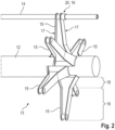
- FIG 2 a schematic view of a reel star 13 is shown.
- the reel star 13 comprises six star arms 15.
- the star arms 15 are arranged one behind the other on the reel support tube 12 in the circumferential direction of the latter and extend like spokes in the radial direction.
- An annular hub (not shown) can be arranged on the reel support tube 12, the star arms 15 being fastened radially on the outside in a stationary manner on the hub.
- the star arms 15 are preferably screwed to the hub or directly to the reel support tube 12 so that they can be replaced individually if damaged.
- the adjacent star arms 15 of the reel star 13 are offset from one another. Adjacent star arms 15 are to be understood here as two consecutive star arms 15 of a reel star 13 in the circumferential direction of the reel support tube 12 .
- the enveloping circle of a star arm 15 resulting from a rotational movement of the reel support tube 12 is axially offset to the enveloping circle of the adjacent star arms 15 .
- the adjacent star arms 15 of a reel star 13 are arranged in sections in their area facing the tine bars 14 with a track offset relative to one another.
- the adjacent star arms 15 of a reel star 13 are arranged track-offset to one another over their entire extent.
- the star arms 15, which are arranged offset relative to one another, are reinforced. These reinforced star arms 15 are more rigid than the star arms 15 of the other reel stars 13 that are arranged on the same track. To strengthen the star arms 15 and in particular to increase their flexural rigidity, the star arms 15 that are offset from one another have a wider extension in the axial direction of the reel support tube 12 than the reel stars 13 with star arms 15 arranged on the same track as each other. Due to the wider extension of the star arms 15, moments and forces can be better transferred from the tine bars 14 to the reel support tube 12. This is also favored by the fact that the reinforced star arms 15 are designed as double T-beams. The T-shaped end faces 17 are aligned in the axial direction of the reel support tube 12 .
- the reinforced star arms 15 comprise a wide trapezoidal area 18 facing the reel support pipe 12 and a narrower, essentially triangular area 19 which adjoins the trapezoidal area 18 radially on the outside.
- the widest side of the trapezoidal area 18 faces the reel support tube 12 .
- the moments acting on the star arms 15 are greater in the wider, trapezoidal area than in the narrower, triangular area, so that the design of the star arms 15 is particularly advantageous with regard to the force and moment transmission between the tine bars 14 and the reel support tube 12 .
- a reel 8 is shown schematically in a front view.
- the reel 8 shown comprises seven reel stars 13.
- the penultimate reel stars 13 comprise adjacent star arms 15 which are arranged in a track-offset manner with respect to one another, with the other reel stars 13 having star arms 15 arranged on the same track as one another.
- the star arms 15, which are arranged offset relative to one another are subjected to a tensile force.
- the tine rods 14 are braced between the two penultimate reel stars 13 .
- Studies have shown that such an arrangement of the reel stars 13 is particularly advantageous for the flexural rigidity of the reel 8 .
- the star arms 15 of the penultimate reel stars 13 are reinforced so that they are designed to absorb the high tensile forces acting due to their increased bending stiffness.
- the reel teeth 7 in the circumferential direction of Reel 8 of adjacent tine bars 14 are offset from each other, so that the envelope curves of the reel tines 7 of adjacent tine bars 14 do not overlap and the effective range of the reel tines 7 is expanded.
- the reel tines 7 are guided along a complex trajectory during a rotation of the reel 8 in order to achieve optimal feeding of the plants towards the cutter bar 9 .
- the reel tines 7 usually engage in the reel. Due to the fact that the star arms 15 of the penultimate reel stars 13 are offset from one another, they can be made wider without colliding with the reel tines 7 . In other words, the off-track arrangement of the reinforced star arms 15 of a reel star 13 is adapted to the track offset of the reel tines 7 .
- an axial bearing 20 is shown with a clamping nut 16 located on an end face of the axial bearing 20 .
- the tine rods 14 are mounted by means of axial bearings 20 in the star arms 15, which are arranged in a track-offset manner with respect to one another.
- the axial bearings 20 are arranged so as to be displaceable on the tine rods 14 and are fixed in their position by means of the clamping nut 16 . This makes it possible in a simple manner to fix the star arms 15 in a position in which a tensile force from the respective star arm 15 acts on the respective tine bar 14 .
Landscapes
- Life Sciences & Earth Sciences (AREA)
- Environmental Sciences (AREA)
- Outside Dividers And Delivering Mechanisms For Harvesters (AREA)
Abstract
Description
- Die Erfindung betrifft eine Haspel für ein Schneidwerk umfassend ein Haspeltragrohr mit darauf angeordneten Haspelsternen, an deren Sternarmen sich parallel zu dem Haspeltragrohr erstreckende Zinkenstangen angeordnet sind.
- Schneidwerke weisen ein Gehäuse sowie eine langgestreckte, sich zwischen Seitenteilen des Gehäuses erstreckende Querfördereinrichtung auf, mittels der Pflanzen hin zu einem mittigen Bereich des Schneidwerks förderbar sind. Ferner umfasst das Schneidwerk mindestens eine Schneideinrichtung, mittels der zu erntende Pflanzen schneidbar sind. Haspeln finden an Schneidwerken Verwendung, um stehendes Erntegut dem Messerbalken und der Querfördereinrichtung zuzuführen. Hierfür ist die Haspel um eine sich entlang des Haspeltragrohrs orientierte Rotationsachse drehbar gelagert und besitzt eine Vielzahl von parallel zu dem Haspeltragrohr und sich über dessen länge erstreckende Zinkenstangen. Die Zinkenstangen umfassen jeweils eine Vielzahl von Haspelzinken. Zusätzlich sind die Zinkenstangen jeweils um ihre Wellenachse drehbeweglich gelagert, sodass der Winkel der Haspelzinken einstellbar ist. Die Haspelzinken werden bei einer Rotation der Haspel von einem Stellmechanismus entlang einer komplexen Bahn geführt, wodurch eine optimierte Zuführung der Pflanzen hin zu dem Messerbalken und der Querfördereinrichtung gewährleistet ist. Die Haspelzinken benachbarter Zinkenstangen sind versetzt zueinander angeordnet, sodass sich die Kurvenbahnen der Haspelzinken benachbarter Zinkenstangen nicht schneiden und ein größerer Wirkbereich von den Haspelzinken erfasst wird.
- Um den Ernteprozess zu optimieren, ist die Schneidwerksbreite zur Erfassung der Pflanzen Wesentlich. Die Schneidwerksbreite beschreibt die Erstreckung des Schneidwerks quer zur Fahrtrichtung und beeinflusst maßgeblich die benötigte Zeitdauer eines Erntevorgangs. Im Zuge immer größer werdender Schneidwerksbreiten steigt die Bestrebung das Gesamtgewicht des Schneidwerks und somit auch der Haspel zu minimieren.
- Für die Haspel ist die Biegesteifigkeit von großer Wichtigkeit. Ein Durchbiegen der Haspel soll vermieden werden, damit über die Schneidwerksbreite der Förderabstand der Haspelzinken zum Messerbalken gleichmäßig ist. Üblicherweise stellt zur Vermeidung eines Durchbiegens das Haspeltragrohr den biegesteifen Träger dar und trägt somit ca. ein Drittel zum Gesamtgewicht der Haspel bei. Das hohe Gewicht des Haspeltragrohrs ist als nachteilig anzusehen.
- Eine Haspel ist in der
DE 10 2011 118 315 A1 offenbart. DieDE 10 2011 118 315 A1 macht es sich zur Aufgabe, das Gewicht der Haspel zu reduzieren. Hierfür wird eine gezielte Verstärkung der endseitig an dem Haspeltragrohr angeordneten Haspelsterne vorgeschlagen. Nachteilig ist jedoch, dass endseitig am Haspeltragrohr üblicherweise der Stellmechanismus zum Einstellen der Position der Haspelzinken vorgesehen ist und somit nur wenig Raum für verstärkt ausgeführte Haspelsterne zur Verfügung steht. - Es ist Aufgabe der Erfindung, die beschriebenen Nachteile des Standes der Technik zu vermeiden und insbesondere eine biegesteifere Haspel mit verringertem Gewicht des Haspelrohrs zu schaffen.
- Diese Aufgabe wird erfindungsgemäß durch die kennzeichnenden Merkmale des Anspruchs 1 gelöst.
- Gemäß dem Anspruch 1 wird eine Haspel für ein Schneidwerk umfassend ein Haspeltragrohr mit darauf angeordneten Haspelsternen, an deren Sternarmen sich parallel zu dem Haspeltragrohr erstreckende Zinkenstangen angeordnet sind, vorgeschlagen, wobei benachbarte Sternarme zumindest eines Haspelsterns zumindest abschnittsweise spurversetzt zueinander angeordnet sind.
- Die Erfindung hat viele Vorteile. Auf den Zinkenstangen befinden sich eine Vielzahl von Haspelzinken. Die Haspelzinken benachbarter Zinkenstangen sind spurversetzt zueinander angeordnet. Eine spurversetzte Anordnung der Sternarme eines Haspelsterns ermöglicht es, dass die jeweiligen Sternarme des Haspelsterns den gleichen Abstand zu den jeweiligen Haspelzinken der dem jeweiligen Sternarm zugeordneten Zinkenstange aufweisen. Hierdurch können die Sternarme eines Haspelsterns breiter und somit Biegesteifer ausgeführt sein, ohne dass der Bewegungsradius der Haspelzinken eingeschränkt ist. Die auf den Zinkenstangen befindlichen Haspelzinken können kollisionsfrei in die Haspel eingreifen. Durch die Anordnung der Haspelsterne mit spurversetzten Sternarmen wird eine biegesteifere Ausführung der gesamten Haspel ermöglicht, sodass die auf das Haspeltragrohr wirkenden Momente reduziert sind und somit das Gewicht des Haspeltragrohrs verringerbar ist. Als abschnittsweise spurversetzt ist hier und vorzugsweise zu verstehen, dass der sich bei einer Rotationsbewegung des Haspeltragrohrs ergebende Hüllkreis eines Sternarms zumindest abschnittsweise axial versetzt zu dem Hüllkreis der benachbarten Sternarme ist.
- Vorzugsweise können die benachbarten Sternarme des zumindest einen Haspelsterns zumindest endseitig in einem den Zinkenstangen zugewandten Bereich spurversetzt zueinander angeordnet sein.
- In einer vorteilhaften Weiterbildung ist vorgesehen, dass die Sternarme der vorletzten Haspelsterne spurversetzt zueinander angeordnet sind. Untersuchungen haben gezeigt, dass eine derartige Anordnung besonders vorteilhaft zur Erhöhung der Biegesteifigkeit der Haspel ist. Ein weiterer Vorteil einer zu den Stirnseiten beabstandeten Positionierung der spurversetzten Sternarme ergibt sich dadurch, dass an den Stirnseiten der Haspel die Stellmechanik zur Führung der Haspelzinken entlang einer Kurvenbahn angeordnet ist und somit an den Stirnseiten wenig Bauraum zur Anordnung spurversetzter Sternarme zur Verfügung steht.
- In einer weiteren vorteilhaften Weiterbildung können die zumindest abschnittsweise spurversetzt zueinander angeordneten Sternarme verstärkt ausgeführt sein, wobei vorzugsweise die verstärkt ausgeführten Sternarme gegenüber den Sternarmen der weiteren Haspelsterne, die insbesondere spurgleich zueinander angeordnete Sternarme aufweisen, biegesteifer ausgeführt sind. Durch die verstärkte Ausführung der Sternarme wird die Übertragung von Momenten und Kräften zwischen den Zinkenstangen und dem Haspeltragrohr begünstigt. Zur Gewichtsreduzierung der Haspel ist es bevorzugt, dass ausschließlich zwei auf dem Haspeltragrohr angeordnete Haspelsterne spurversetzt und verstärkt ausgeführte Sternarme aufweisen.
- Vorzugsweise können zur Verstärkung die Sternarme eine breitere Erstreckung als die Sternarme der weiteren Haspelsterne, die insbesondere mit spurgleich zueinander angeordneten Sternarmen ausgeführt sind, aufweisen. Mit anderen Worten erstrecken sich die verstärkt ausgeführten Sternarme in axialer Richtung des Haspeltragrohrs über eine längere Strecke als die spurgleich zueinander angeordneten Sternarme.
- In einer vorteilhaften Ausgestaltung können zur Verstärkung die Sternarme als doppel T-Träger ausgeführt sein, wobei vorzugsweise der jeweilige doppel T-Träger einen dem Haspeltragrohr zugewandten trapezförmigen Bereich und einen sich hieran in radialer Richtung des Haspeltragrohrs anschließenden im Wesentlichen dreieckförmigen Bereich umfasst, wobei der dreieckförmige Bereich schmaler als der trapezförmige Bereich ausgebildet ist. Eine derartige Ausgestaltung ist besonders vorteilhaft zur Übertragung von Kräften und Momenten zwischen den Zinkenstangen und dem Haspeltragrohr, da die wirkenden Momente verstärkt in dem trapezförmigen Bereich wirken, der breiter und somit biegesteifer als der dreieckförmige Bereich ausgeführt ist. Der schmalere im Wesentlichen dreieckförmige Bereich ist benachbart zum Hüllkreis der Haspelzinken, wobei durch die schmalere Ausführung dieses Bereichs eine Kollision mit den Haspelzinken vermeidbar ist.
- Eine weitere vorteilhafte Ausgestaltung sieht vor, dass die Zinkenstangen durch die zumindest abschnittsweise spurversetzt zueinander angeordneten Sternarme mit einer Zugkraft beaufschlagt sind, wobei vorzugsweise die jeweils vorletzten Haspelsterne jeweils zumindest abschnittsweise spurversetzt zueinander angeordnete Sternarme aufweisen und die Zinkenstangen zwischen diesen vorletzten Haspelsternen verspannt sind. Die Verspannung der Zinkenstangen zwischen den Haspelsternen, sodass diese vorzugsweise im Betriebszustand ausschließlich Zugkräfte aufnehmen und somit dauerhaft mit einer Zugkraft beaufschlagt sind, ermöglicht es die Biegesteifigkeit der Haspel zu erhöhen. Zugleich kann das Gewicht des Haspeltragrohrs reduziert werden, sodass das Gesamtgewicht der Haspel abnimmt.
- Besonders bevorzugt ist es, wenn die Zinkenstangen mittels Axiallagern an den Sternarmen gelagert sind, wobei vorzugsweise die Axiallager verschiebbeweglich auf den Zinkenstangen angeordnet sind und die Axiallager mittels zumindest einer Feststelleinrichtung, insbesondere einer Klemmutter in ihrer Position festgesetzt sind. Hierdurch sind die Zinkenstangen auf einfache Art und Weise mit einer Zugkraft beaufschlagbar.
- Insbesondere können die Zinkenstangen eine Vielzahl von Haspelzinken umfassen, wobei die Haspelzinken benachbarter Zinkenstangen spurversetzt zueinander angeordnet sind.
- Weitere vorteilhafte Ausgestaltungen sind Gegenstand weiterer Unteransprüche und werden nachfolgend an Hand eines in mehreren Figuren dargestellten Ausführungsbeispiels beschrieben. Es zeigen:
- Figur 1
- Eine Seitenansicht des vorderen Bereichs eines Mähdreschers mit einem daran angeordneten Schneidwerk;
- Figur 2
- Eine schematische Ansicht eines Haspelsterns;
- Figur 3
- Eine Frontansicht einer Haspel;
- Fig. 4
- Ein Axiallager mit einer Klemmutter
- Bei einem in der
Fig. 1 teilweise dargestellten Mähdrescher 1 mit Schneidwerk 2, Triebrädern 3, Fahrerkabine 4, Drescheinrichtung 5 und Korntank 6 wird das Erntegut von den Haspelzinken 7 der Haspel 8 erfasst und zum Messerbalken 9 geleitet und von diesem abgeschnitten. Das geschnittene Gut wird anschließend von der Einzugsschnecke 10 kontinuierlich zur Mitte gefördert und dort an den Schrägförderer 11 übergeben, der das Erntegut der Drescheinrichtung 5 zuführt. Die Haspel 8 ist in horizontaler und vertikaler Richtung einstellbar und unterstützt die gleichmäßige Erntegutförderung. Sie besteht aus einem axial angeordneten und angetriebenen Haspeltragrohr 12, an der in Abständen Haspelsterne 13 befestigt sind. An deren Umfang sind mehrere, über die gesamte Breite der Haspel 8 durchgehende Zinkenstangen 14 angeordnet. An diesen sind mit Abstand gesteuerte Haspelzinken 7 befestigt, die als Einfach- oder Doppelzinken ausgebildet sind und aus federndem Stahl oder Kunststoff hergestellt sind. Die Zinkenstrangen 14 bestehen aus einem gewalzten oder stranggepressten Hohlprofil. - In
Figur 2 ist eine schematische Ansicht eines Haspelsterns 13 dargestellt. Der Haspelstern 13 umfasst sechs Sternarme 15. Die Sternarme 15 sind in Umfangsrichtung des Haspeltragrohrs 12 hintereinander auf diesem angeordnet und erstrecken sich speichenförmig in radialer Richtung. Auf dem Haspeltragrohr 12 kann eine ringförmige Nabe (nicht gezeigt) angeordnet sein, wobei die Sternarme 15 radial außenseitig ortsfest auf der Nabe befestigt sind. Die Sternarme 15 sind vorzugsweise mit der Nabe oder unmittelbar mit dem Haspeltragrohr 12 verschraubt, sodass diese bei einer Beschädigung einzeln austauschbar sind. Die benachbarten Sternarme 15 des Haspelsterns 13 sind zueinander spurversetzt angeordnet. Als benachbarte Sternarme 15 sind hier zwei in Umfangsrichtung des Haspeltragrohrs 12 aufeinanderfolgende Sternarme 15 eines Haspelsterns 13 zu verstehen. Als spurversetzt ist hier und vorzugsweise zu verstehen, dass der sich bei einer Rotationsbewegung des Haspeltragrohrs 12 ergebende Hüllkreis eines Sternarms 15 axial versetzt zu dem Hüllkreis der benachbarten Sternarme 15 ist. In einer ersten Ausführungsform sind die benachbarten Sternarme 15 eines Haspelsterns 13 abschnittsweise in ihrem den Zinkenstangen 14 zugewandten Bereich spurversetzt zueinander angeordnet. In einer alternativen und inFig. 2 gezeigten Ausführungsform sind die benachbarten Sternarme 15 eines Haspelsterns 13 in ihrer gesamten Erstreckung spurversetzt zueinander angeordnet. - Die spurversetzt zueinander angeordneten Sternarme 15 sind verstärkt ausgeführt. Diese verstärkt ausgeführten Sternarme 15 sind biegesteifer als die spurgleich angeordneten Sternarmen 15 der weiteren Haspelsterne 13. Zur Verstärkung der Sternarme 15 und insbesondere zur Erhöhung deren Biegesteifigkeit, weisen die spurversetzt zueinander angeordneten Sternarme 15 eine breitere Erstreckung in axialer Richtung des Haspeltragrohrs 12 auf als die Haspelsterne 13 mit spurgleich zueinander angeordneten Sternarmen 15. Durch die breitere Erstreckung der Sternarme 15 sind Momente und Kräfte besser von den Zinkenstangen 14 auf das Haspeltragrohr 12 übertragbar. Begünstigt wird dies ebenfalls dadurch, dass die verstärkt ausgeführten Sternarme 15 als doppel T-Träger ausgebildet sind. Die T-förmigen Stirnseiten 17 sind in axialer Richtung des Haspeltragrohrs 12 ausgerichtet.
- Die verstärkt ausgeführten Sternarme 15 umfassen einen dem Haspeltragrohr 12 zugewandten breiten trapezförmigen Bereich 18 und einen schmaleren im Wesentlichen dreieckförmigen Bereich 19, der sich radial außenseitig an den trapezförmigen Bereich 18 anschließt. Die breiteste Seite des trapezförmigen Bereichs 18 ist dem Haspeltragrohr 12 zugewandt. Hierdurch wird eine Kraftübertragung von den Sternarmen 15 auf das Haspeltragrohr 12 begünstigt. Die auf die Sternarme 15 wirkenden Momente sind in dem breiteren, trapezförmigen Bereich größer als in dem schmaleren dreieckförmigen Bereich, sodass die Ausführung der Sternarme 15 hinsichtlich der Kraft- und Momentübertragung zwischen den Zinkenstangen 14 und dem Haspeltragrohr 12 besonders vorteilhaft ist.
- In
Figur 3 ist eine Haspel 8 schematisch in einer Frontansicht dargestellt. Die dargestellte Haspel 8 umfasst sieben Haspelsterne 13. Hier und vorzugsweise umfassen die vorletzten Haspelsterne 13 benachbarte Sternarme 15, die spurversetzt zueinander angeordnet sind, wobei die weiteren Haspelsterne 13 mit spurgleich zueinander angeordneten Sternarmen 15 ausgebildet sind. Zur Erhöhung der Biegesteifigkeit der Haspel 8 sind die spurversetzt zueinander angeordneten Sternarme 15 mit einer Zugkraft beaufschlagt. Hierfür sind die Zinkenstangen 14 zwischen den beiden vorletzten Haspelsternen 13 verspannt. Untersuchungen haben gezeigt, dass eine derartige Anordnung der Haspelsterne 13 besonders vorteilhaft für die Biegesteifigkeit der Haspel 8 ist. Die Sternarme 15 der vorletzten Haspelsterne 13 sind verstärkt ausgeführt, sodass diese aufgrund ihrer erhöhten Biegesteifigkeit zur Aufnahme der hohen wirkenden Zugkräfte ausgebildet sind. - Auf den Zinkenstangen 14 sind eine Mehrzahl von in
Fig. 3 exemplarisch angedeuteten und an sich bekannten Haspelzinken 7 angeordnet. Die Haspelzinken 7 von in Umfangrichtung der Haspel 8 benachbarter Zinkenstangen 14 sind spurversetzt zueinander angeordnet, sodass die Hüllkurven der Haspelzinken 7 benachbarter Zinkenstangen 14 sich nicht überlagern und der Wirkbereich der Haspelzinken 7 erweitert ist. Die Haspelzinken 7 werden während einer Rotation der Haspel 8 entlang einer komplexen Bahnkurve geführt, um eine optimale Zuführung der Pflanzen hin zu dem Messerbalken 9 zu erreichen. Hierbei greifen die Haspelzinken 7 üblicherweise in die Haspel ein. Dadurch, dass die Sternarme 15 der vorletzten Haspelsterne 13 spurversetzt zueinander angeordnet sind, können diese breiter ausgeführt werden, ohne dass diese mit den Haspelzinken 7 kollidieren. Mit anderen Worten ist die spurversetzte Anordnung der verstärkt ausgeführten Sternarme 15 eines Haspelsterns 13 an den Spurversatz der Haspelzinken 7 angepasst. - In
Figur 4 ist ein Axiallager 20 mit einer an einer Stirnseite des Axiallagers 20 befindlichen Klemmutter 16 dargestellt. Hier und vorzugsweise sind die Zinkenstangen 14 mittels Axiallagern 20 in den spurversetzt zueinander angeordneten Sternarmen 15 gelagert. Die Axiallager 20 sind hierfür verschiebbeweglich auf den Zinkenstangen 14 angeordnet und mittels der Klemmutter 16 in ihrer Position fixiert. Dies ermöglicht auf einfache Art und Weise die Sternarme 15 in einer Position zu fixieren, in der eine Zugkraft von dem jeweiligen Sternarm 15 auf die jeweilige Zinkenstange 14 wirkt. -
- 1
- Mähdrescher
- 2
- Schneidwerk
- 3
- Triebrad
- 4
- Fahrerkabine
- 5
- Drescheinrichtung
- 6
- Korntank
- 7
- Haspelzinken
- 8
- Haspel
- 9
- Messerbalken
- 10
- Einzugsschnecke
- 11
- Schrägförderer
- 12
- Haspeltragrohr
- 13
- Haspelstern
- 14
- Zinkenstange
- 15
- Sternarm
- 16
- Klemmutter
- 17
- Stirnseite
- 18
- Trapezförmiger Bereich
- 19
- Dreieckförmiger Bereich
- 20
- Axiallager
Claims (9)
- Haspel (8) für ein Schneidwerk (2) umfassend ein Haspeltragrohr (12) mit darauf angeordneten Haspelsternen (13), an deren Sternarmen (15) sich parallel zu dem Haspeltragrohr (12) erstreckende Zinkenstangen (14) angeordnet sind,
dadurch gekennzeichnet, dass
benachbarte Sternarme (15) zumindest eines Haspelsterns (13) zumindest abschnittsweise spurversetzt zueinander angeordnet sind. - Haspel (8) nach Anspruch 1, dadurch gekennzeichnet, dass die benachbarten Sternarme (15) des zumindest einen Haspelsterns (13) zumindest endseitig in einem den Zinkenstangen (14) zugewandten Bereich spurversetzt zueinander angeordnet sind.
- Haspel (8) nach einem der Ansprüche 1 bis 2, dadurch gekennzeichnet, dass die Sternarme (15) der vorletzten Haspelsterne (13) spurversetzt zueinander angeordnet sind.
- Haspel (8) nach einem der Ansprüche 1 bis 3, dadurch gekennzeichnet, dass die zumindest abschnittsweise spurversetzt zueinander angeordneten Sternarme (15) verstärkt ausgeführt sind, wobei vorzugsweise die verstärkt ausgeführten Sternarme (15) gegenüber den Sternarmen (15) der weiteren Haspelsterne (13), die insbesondere spurgleich zueinander angeordnete Sternarme (15) aufweisen, biegesteifer ausgeführt sind.
- Haspel (8) nach Anspruch 4, dadurch gekennzeichnet, dass zur Verstärkung die Sternarme (15) eine breitere Erstreckung als die Sternarme (15) der weiteren Haspelsterne (13), die insbesondere mit spurgleich zueinander angeordneten Sternarmen (15) ausgeführt sind, aufweisen.
- Haspel (8) nach einem der Ansprüche 4 bis 5, dadurch gekennzeichnet, dass zur Verstärkung die Sternarme (15) als doppel T-Träger ausgeführt sind, wobei vorzugsweise der jeweilige doppel T-Träger einen dem Haspeltragrohr (12) zugewandten trapezförmigen Bereich (18) und einen sich hieran in radialer Richtung des Haspeltragrohrs (12) anschließenden im Wesentlichen dreieckförmigen Bereich (19) umfasst, wobei der dreieckförmige Bereich (19) schmaler als der trapezförmige Bereich (18) ausgebildet ist.
- Haspel (8) nach einem der Ansprüche 1 bis 6, dadurch gekennzeichnet, dass die Zinkenstangen (14) durch die zumindest abschnittsweise spurversetzt zueinander angeordneten Sternarme (15) mit einer Zugkraft beaufschlagt sind, wobei vorzugsweise die jeweils vorletzten Haspelsterne (13) jeweils zumindest abschnittsweise spurversetzt zueinander angeordnete Sternarme (15) aufweisen und die Zinkenstangen (14) zwischen diesen vorletzten Haspelsternen (13) verspannt sind.
- Haspel (8) nach einem der Ansprüche 1 bis 7, dadurch gekennzeichnet, dass die Zinkenstangen (14) mittels Axiallagern (20) an den Sternarmen (15) gelagert sind, wobei vorzugsweise die Axiallager (20) verschiebbeweglich auf den Zinkenstangen (14) angeordnet sind und die Axiallager (20) mittels zumindest einer Feststelleinrichtung, insbesondere einer Klemmutter (16) in ihrer Position festgesetzt sind.
- Haspel (8) nach einem der Ansprüche 1 bis 8, dadurch gekennzeichnet, dass die Zinkenstangen (14) eine Vielzahl von Haspelzinken (7) umfassen, wobei die Haspelzinken (7) benachbarter Zinkenstangen (14) spurversetzt zueinander angeordnet sind.
Applications Claiming Priority (1)
| Application Number | Priority Date | Filing Date | Title |
|---|---|---|---|
| DE102021132420.3A DE102021132420A1 (de) | 2021-12-09 | 2021-12-09 | Haspel |
Publications (2)
| Publication Number | Publication Date |
|---|---|
| EP4193825A1 true EP4193825A1 (de) | 2023-06-14 |
| EP4193825B1 EP4193825B1 (de) | 2024-05-15 |
Family
ID=83903010
Family Applications (1)
| Application Number | Title | Priority Date | Filing Date |
|---|---|---|---|
| EP22202733.6A Active EP4193825B1 (de) | 2021-12-09 | 2022-10-20 | Haspel |
Country Status (2)
| Country | Link |
|---|---|
| EP (1) | EP4193825B1 (de) |
| DE (1) | DE102021132420A1 (de) |
Citations (4)
| Publication number | Priority date | Publication date | Assignee | Title |
|---|---|---|---|---|
| US4016710A (en) * | 1976-05-12 | 1977-04-12 | J. E. Love Company | Bat support spider for a harvester reel |
| EP1716740A1 (de) * | 2005-04-26 | 2006-11-02 | CLAAS Selbstfahrende Erntemaschinen GmbH | Schneidwerk |
| DE102011118315A1 (de) | 2011-11-11 | 2013-05-16 | Biso Schrattenecker Gmbh | Haspel für eine Erntemaschine |
| EP2798941A1 (de) * | 2013-05-02 | 2014-11-05 | Deere & Company | Haspel für einen Erntekopf |
-
2021
- 2021-12-09 DE DE102021132420.3A patent/DE102021132420A1/de active Pending
-
2022
- 2022-10-20 EP EP22202733.6A patent/EP4193825B1/de active Active
Patent Citations (4)
| Publication number | Priority date | Publication date | Assignee | Title |
|---|---|---|---|---|
| US4016710A (en) * | 1976-05-12 | 1977-04-12 | J. E. Love Company | Bat support spider for a harvester reel |
| EP1716740A1 (de) * | 2005-04-26 | 2006-11-02 | CLAAS Selbstfahrende Erntemaschinen GmbH | Schneidwerk |
| DE102011118315A1 (de) | 2011-11-11 | 2013-05-16 | Biso Schrattenecker Gmbh | Haspel für eine Erntemaschine |
| EP2798941A1 (de) * | 2013-05-02 | 2014-11-05 | Deere & Company | Haspel für einen Erntekopf |
Also Published As
| Publication number | Publication date |
|---|---|
| EP4193825B1 (de) | 2024-05-15 |
| DE102021132420A1 (de) | 2023-06-15 |
Similar Documents
| Publication | Publication Date | Title |
|---|---|---|
| EP0880885B1 (de) | Mähdrescher | |
| EP0824856B1 (de) | Maschine zum reihenunabhängigen Mähen und Häckseln von Mais und dgl. stengelartigem Erntegut | |
| DE19861245B4 (de) | Mähdrescher mit einem Rotationsförderer | |
| DE2848451A1 (de) | Reihenschneid-anbaugeraet | |
| EP0748583A1 (de) | Mähdrescher | |
| EP2481277A1 (de) | Dreschwerk eines Mähdreschers | |
| DE102011118315A1 (de) | Haspel für eine Erntemaschine | |
| DE2609641C2 (de) | Rotor für Mähdrescher der Axialflußbauart | |
| DE2262826A1 (de) | Maehwerkhaspel mit zinkensteuerung | |
| DE102018121273A1 (de) | Aufnahmevorrichtung für eine Erntemaschine mit Stützelementen für die Abstreifer der Aufnahmevorrichtung | |
| EP4193825B1 (de) | Haspel | |
| DE19802672C2 (de) | Mähdrescher | |
| DE102012204416A1 (de) | Mehrtrommeldreschwerk | |
| EP2179639A1 (de) | Lageranordnung für einen Zinkenträger an einer Haspel einer Erntemaschine | |
| EP1709861B1 (de) | Auswurfkrümmer für einen Feldhäcksler | |
| DE2713502A1 (de) | Querfoerdereinrichtung auf einem maehdrescher-schneidtisch | |
| DE2835774A1 (de) | Dreschspalteinstellung fuer maehdrescher der axialflussbauart | |
| DE202019104058U1 (de) | Aufnahmevorrichtung mit in Gruppen angeordneten Förderzinken | |
| EP4011190B1 (de) | Strohhäcksler | |
| EP3763198B1 (de) | Dreschtrommel einer dreschvorrichtung für einen mähdrescher | |
| DE102011083059B4 (de) | Dreschwerk mit einem unterschlächtig fördernden Abgabeförderer | |
| DE102004001383B3 (de) | Haspel für eine Erntegutbergungseinrichtung | |
| EP4118948B1 (de) | Haspel für eine erntemaschine | |
| DE29909358U1 (de) | Pflückvorsatz für Geräte zum Ernten von Körnerfrüchten | |
| DE102004028550A1 (de) | Haspel für eine Erntegutbergungseinrichtung |
Legal Events
| Date | Code | Title | Description |
|---|---|---|---|
| PUAI | Public reference made under article 153(3) epc to a published international application that has entered the european phase |
Free format text: ORIGINAL CODE: 0009012 |
|
| STAA | Information on the status of an ep patent application or granted ep patent |
Free format text: STATUS: THE APPLICATION HAS BEEN PUBLISHED |
|
| AK | Designated contracting states |
Kind code of ref document: A1 Designated state(s): AL AT BE BG CH CY CZ DE DK EE ES FI FR GB GR HR HU IE IS IT LI LT LU LV MC ME MK MT NL NO PL PT RO RS SE SI SK SM TR |
|
| P01 | Opt-out of the competence of the unified patent court (upc) registered |
Effective date: 20230614 |
|
| STAA | Information on the status of an ep patent application or granted ep patent |
Free format text: STATUS: REQUEST FOR EXAMINATION WAS MADE |
|
| 17P | Request for examination filed |
Effective date: 20231214 |
|
| RBV | Designated contracting states (corrected) |
Designated state(s): AL AT BE BG CH CY CZ DE DK EE ES FI FR GB GR HR HU IE IS IT LI LT LU LV MC ME MK MT NL NO PL PT RO RS SE SI SK SM TR |
|
| GRAP | Despatch of communication of intention to grant a patent |
Free format text: ORIGINAL CODE: EPIDOSNIGR1 |
|
| STAA | Information on the status of an ep patent application or granted ep patent |
Free format text: STATUS: GRANT OF PATENT IS INTENDED |
|
| RIC1 | Information provided on ipc code assigned before grant |
Ipc: A01D 80/02 20060101ALI20240131BHEP Ipc: A01D 57/02 20060101AFI20240131BHEP |
|
| INTG | Intention to grant announced |
Effective date: 20240213 |
|
| GRAS | Grant fee paid |
Free format text: ORIGINAL CODE: EPIDOSNIGR3 |
|
| GRAA | (expected) grant |
Free format text: ORIGINAL CODE: 0009210 |
|
| STAA | Information on the status of an ep patent application or granted ep patent |
Free format text: STATUS: THE PATENT HAS BEEN GRANTED |
|
| AK | Designated contracting states |
Kind code of ref document: B1 Designated state(s): AL AT BE BG CH CY CZ DE DK EE ES FI FR GB GR HR HU IE IS IT LI LT LU LV MC ME MK MT NL NO PL PT RO RS SE SI SK SM TR |
|
| REG | Reference to a national code |
Ref country code: CH Ref legal event code: EP |
|
| REG | Reference to a national code |
Ref country code: IE Ref legal event code: FG4D Free format text: LANGUAGE OF EP DOCUMENT: GERMAN |
|
| REG | Reference to a national code |
Ref country code: DE Ref legal event code: R096 Ref document number: 502022000905 Country of ref document: DE |
|
| REG | Reference to a national code |
Ref country code: LT Ref legal event code: MG9D |
|
| REG | Reference to a national code |
Ref country code: NL Ref legal event code: MP Effective date: 20240515 |
|
| PG25 | Lapsed in a contracting state [announced via postgrant information from national office to epo] |
Ref country code: IS Free format text: LAPSE BECAUSE OF FAILURE TO SUBMIT A TRANSLATION OF THE DESCRIPTION OR TO PAY THE FEE WITHIN THE PRESCRIBED TIME-LIMIT Effective date: 20240915 |
|
| PG25 | Lapsed in a contracting state [announced via postgrant information from national office to epo] |
Ref country code: BG Free format text: LAPSE BECAUSE OF FAILURE TO SUBMIT A TRANSLATION OF THE DESCRIPTION OR TO PAY THE FEE WITHIN THE PRESCRIBED TIME-LIMIT Effective date: 20240515 |
|
| PG25 | Lapsed in a contracting state [announced via postgrant information from national office to epo] |
Ref country code: HR Free format text: LAPSE BECAUSE OF FAILURE TO SUBMIT A TRANSLATION OF THE DESCRIPTION OR TO PAY THE FEE WITHIN THE PRESCRIBED TIME-LIMIT Effective date: 20240515 Ref country code: FI Free format text: LAPSE BECAUSE OF FAILURE TO SUBMIT A TRANSLATION OF THE DESCRIPTION OR TO PAY THE FEE WITHIN THE PRESCRIBED TIME-LIMIT Effective date: 20240515 |
|
| PG25 | Lapsed in a contracting state [announced via postgrant information from national office to epo] |
Ref country code: GR Free format text: LAPSE BECAUSE OF FAILURE TO SUBMIT A TRANSLATION OF THE DESCRIPTION OR TO PAY THE FEE WITHIN THE PRESCRIBED TIME-LIMIT Effective date: 20240816 |
|
| PG25 | Lapsed in a contracting state [announced via postgrant information from national office to epo] |
Ref country code: PT Free format text: LAPSE BECAUSE OF FAILURE TO SUBMIT A TRANSLATION OF THE DESCRIPTION OR TO PAY THE FEE WITHIN THE PRESCRIBED TIME-LIMIT Effective date: 20240916 |
|
| PG25 | Lapsed in a contracting state [announced via postgrant information from national office to epo] |
Ref country code: NL Free format text: LAPSE BECAUSE OF FAILURE TO SUBMIT A TRANSLATION OF THE DESCRIPTION OR TO PAY THE FEE WITHIN THE PRESCRIBED TIME-LIMIT Effective date: 20240515 |
|
| PG25 | Lapsed in a contracting state [announced via postgrant information from national office to epo] |
Ref country code: ES Free format text: LAPSE BECAUSE OF FAILURE TO SUBMIT A TRANSLATION OF THE DESCRIPTION OR TO PAY THE FEE WITHIN THE PRESCRIBED TIME-LIMIT Effective date: 20240515 |
|
| PG25 | Lapsed in a contracting state [announced via postgrant information from national office to epo] |
Ref country code: PL Free format text: LAPSE BECAUSE OF FAILURE TO SUBMIT A TRANSLATION OF THE DESCRIPTION OR TO PAY THE FEE WITHIN THE PRESCRIBED TIME-LIMIT Effective date: 20240515 |
|
| PG25 | Lapsed in a contracting state [announced via postgrant information from national office to epo] |
Ref country code: LV Free format text: LAPSE BECAUSE OF FAILURE TO SUBMIT A TRANSLATION OF THE DESCRIPTION OR TO PAY THE FEE WITHIN THE PRESCRIBED TIME-LIMIT Effective date: 20240515 |
|
| PG25 | Lapsed in a contracting state [announced via postgrant information from national office to epo] |
Ref country code: PT Free format text: LAPSE BECAUSE OF FAILURE TO SUBMIT A TRANSLATION OF THE DESCRIPTION OR TO PAY THE FEE WITHIN THE PRESCRIBED TIME-LIMIT Effective date: 20240916 Ref country code: PL Free format text: LAPSE BECAUSE OF FAILURE TO SUBMIT A TRANSLATION OF THE DESCRIPTION OR TO PAY THE FEE WITHIN THE PRESCRIBED TIME-LIMIT Effective date: 20240515 Ref country code: NO Free format text: LAPSE BECAUSE OF FAILURE TO SUBMIT A TRANSLATION OF THE DESCRIPTION OR TO PAY THE FEE WITHIN THE PRESCRIBED TIME-LIMIT Effective date: 20240815 Ref country code: NL Free format text: LAPSE BECAUSE OF FAILURE TO SUBMIT A TRANSLATION OF THE DESCRIPTION OR TO PAY THE FEE WITHIN THE PRESCRIBED TIME-LIMIT Effective date: 20240515 Ref country code: LV Free format text: LAPSE BECAUSE OF FAILURE TO SUBMIT A TRANSLATION OF THE DESCRIPTION OR TO PAY THE FEE WITHIN THE PRESCRIBED TIME-LIMIT Effective date: 20240515 Ref country code: IS Free format text: LAPSE BECAUSE OF FAILURE TO SUBMIT A TRANSLATION OF THE DESCRIPTION OR TO PAY THE FEE WITHIN THE PRESCRIBED TIME-LIMIT Effective date: 20240915 Ref country code: HR Free format text: LAPSE BECAUSE OF FAILURE TO SUBMIT A TRANSLATION OF THE DESCRIPTION OR TO PAY THE FEE WITHIN THE PRESCRIBED TIME-LIMIT Effective date: 20240515 Ref country code: GR Free format text: LAPSE BECAUSE OF FAILURE TO SUBMIT A TRANSLATION OF THE DESCRIPTION OR TO PAY THE FEE WITHIN THE PRESCRIBED TIME-LIMIT Effective date: 20240816 Ref country code: FI Free format text: LAPSE BECAUSE OF FAILURE TO SUBMIT A TRANSLATION OF THE DESCRIPTION OR TO PAY THE FEE WITHIN THE PRESCRIBED TIME-LIMIT Effective date: 20240515 Ref country code: ES Free format text: LAPSE BECAUSE OF FAILURE TO SUBMIT A TRANSLATION OF THE DESCRIPTION OR TO PAY THE FEE WITHIN THE PRESCRIBED TIME-LIMIT Effective date: 20240515 Ref country code: BG Free format text: LAPSE BECAUSE OF FAILURE TO SUBMIT A TRANSLATION OF THE DESCRIPTION OR TO PAY THE FEE WITHIN THE PRESCRIBED TIME-LIMIT Effective date: 20240515 Ref country code: RS Free format text: LAPSE BECAUSE OF FAILURE TO SUBMIT A TRANSLATION OF THE DESCRIPTION OR TO PAY THE FEE WITHIN THE PRESCRIBED TIME-LIMIT Effective date: 20240815 |
|
| PG25 | Lapsed in a contracting state [announced via postgrant information from national office to epo] |
Ref country code: DK Free format text: LAPSE BECAUSE OF FAILURE TO SUBMIT A TRANSLATION OF THE DESCRIPTION OR TO PAY THE FEE WITHIN THE PRESCRIBED TIME-LIMIT Effective date: 20240515 |
|
| PG25 | Lapsed in a contracting state [announced via postgrant information from national office to epo] |
Ref country code: EE Free format text: LAPSE BECAUSE OF FAILURE TO SUBMIT A TRANSLATION OF THE DESCRIPTION OR TO PAY THE FEE WITHIN THE PRESCRIBED TIME-LIMIT Effective date: 20240515 |
|
| PG25 | Lapsed in a contracting state [announced via postgrant information from national office to epo] |
Ref country code: CZ Free format text: LAPSE BECAUSE OF FAILURE TO SUBMIT A TRANSLATION OF THE DESCRIPTION OR TO PAY THE FEE WITHIN THE PRESCRIBED TIME-LIMIT Effective date: 20240515 |
|
| PG25 | Lapsed in a contracting state [announced via postgrant information from national office to epo] |
Ref country code: SK Free format text: LAPSE BECAUSE OF FAILURE TO SUBMIT A TRANSLATION OF THE DESCRIPTION OR TO PAY THE FEE WITHIN THE PRESCRIBED TIME-LIMIT Effective date: 20240515 Ref country code: RO Free format text: LAPSE BECAUSE OF FAILURE TO SUBMIT A TRANSLATION OF THE DESCRIPTION OR TO PAY THE FEE WITHIN THE PRESCRIBED TIME-LIMIT Effective date: 20240515 |
|
| PG25 | Lapsed in a contracting state [announced via postgrant information from national office to epo] |
Ref country code: SM Free format text: LAPSE BECAUSE OF FAILURE TO SUBMIT A TRANSLATION OF THE DESCRIPTION OR TO PAY THE FEE WITHIN THE PRESCRIBED TIME-LIMIT Effective date: 20240515 |
|
| PG25 | Lapsed in a contracting state [announced via postgrant information from national office to epo] |
Ref country code: SM Free format text: LAPSE BECAUSE OF FAILURE TO SUBMIT A TRANSLATION OF THE DESCRIPTION OR TO PAY THE FEE WITHIN THE PRESCRIBED TIME-LIMIT Effective date: 20240515 Ref country code: SK Free format text: LAPSE BECAUSE OF FAILURE TO SUBMIT A TRANSLATION OF THE DESCRIPTION OR TO PAY THE FEE WITHIN THE PRESCRIBED TIME-LIMIT Effective date: 20240515 Ref country code: RO Free format text: LAPSE BECAUSE OF FAILURE TO SUBMIT A TRANSLATION OF THE DESCRIPTION OR TO PAY THE FEE WITHIN THE PRESCRIBED TIME-LIMIT Effective date: 20240515 Ref country code: EE Free format text: LAPSE BECAUSE OF FAILURE TO SUBMIT A TRANSLATION OF THE DESCRIPTION OR TO PAY THE FEE WITHIN THE PRESCRIBED TIME-LIMIT Effective date: 20240515 Ref country code: DK Free format text: LAPSE BECAUSE OF FAILURE TO SUBMIT A TRANSLATION OF THE DESCRIPTION OR TO PAY THE FEE WITHIN THE PRESCRIBED TIME-LIMIT Effective date: 20240515 Ref country code: CZ Free format text: LAPSE BECAUSE OF FAILURE TO SUBMIT A TRANSLATION OF THE DESCRIPTION OR TO PAY THE FEE WITHIN THE PRESCRIBED TIME-LIMIT Effective date: 20240515 |
|
| REG | Reference to a national code |
Ref country code: DE Ref legal event code: R097 Ref document number: 502022000905 Country of ref document: DE |
|
| PLBE | No opposition filed within time limit |
Free format text: ORIGINAL CODE: 0009261 |
|
| STAA | Information on the status of an ep patent application or granted ep patent |
Free format text: STATUS: NO OPPOSITION FILED WITHIN TIME LIMIT |
|
| 26N | No opposition filed |
Effective date: 20250218 |
|
| PG25 | Lapsed in a contracting state [announced via postgrant information from national office to epo] |
Ref country code: SI Free format text: LAPSE BECAUSE OF FAILURE TO SUBMIT A TRANSLATION OF THE DESCRIPTION OR TO PAY THE FEE WITHIN THE PRESCRIBED TIME-LIMIT Effective date: 20240515 |
|
| PG25 | Lapsed in a contracting state [announced via postgrant information from national office to epo] |
Ref country code: MC Free format text: LAPSE BECAUSE OF FAILURE TO SUBMIT A TRANSLATION OF THE DESCRIPTION OR TO PAY THE FEE WITHIN THE PRESCRIBED TIME-LIMIT Effective date: 20240515 |
|
| PG25 | Lapsed in a contracting state [announced via postgrant information from national office to epo] |
Ref country code: LU Free format text: LAPSE BECAUSE OF NON-PAYMENT OF DUE FEES Effective date: 20241020 |
|
| PG25 | Lapsed in a contracting state [announced via postgrant information from national office to epo] |
Ref country code: FR Free format text: LAPSE BECAUSE OF NON-PAYMENT OF DUE FEES Effective date: 20241031 |
|
| PG25 | Lapsed in a contracting state [announced via postgrant information from national office to epo] |
Ref country code: SE Free format text: LAPSE BECAUSE OF FAILURE TO SUBMIT A TRANSLATION OF THE DESCRIPTION OR TO PAY THE FEE WITHIN THE PRESCRIBED TIME-LIMIT Effective date: 20240515 |
|
| PG25 | Lapsed in a contracting state [announced via postgrant information from national office to epo] |
Ref country code: IE Free format text: LAPSE BECAUSE OF NON-PAYMENT OF DUE FEES Effective date: 20241020 |
|
| PGFP | Annual fee paid to national office [announced via postgrant information from national office to epo] |
Ref country code: DE Payment date: 20251021 Year of fee payment: 4 |
|
| PGFP | Annual fee paid to national office [announced via postgrant information from national office to epo] |
Ref country code: AT Payment date: 20260113 Year of fee payment: 4 |
|
| PGFP | Annual fee paid to national office [announced via postgrant information from national office to epo] |
Ref country code: IT Payment date: 20251031 Year of fee payment: 4 |
|
| PGFP | Annual fee paid to national office [announced via postgrant information from national office to epo] |
Ref country code: BE Payment date: 20251021 Year of fee payment: 4 |
|
| PG25 | Lapsed in a contracting state [announced via postgrant information from national office to epo] |
Ref country code: CY Free format text: LAPSE BECAUSE OF FAILURE TO SUBMIT A TRANSLATION OF THE DESCRIPTION OR TO PAY THE FEE WITHIN THE PRESCRIBED TIME-LIMIT; INVALID AB INITIO Effective date: 20221020 |
|
| PG25 | Lapsed in a contracting state [announced via postgrant information from national office to epo] |
Ref country code: HU Free format text: LAPSE BECAUSE OF FAILURE TO SUBMIT A TRANSLATION OF THE DESCRIPTION OR TO PAY THE FEE WITHIN THE PRESCRIBED TIME-LIMIT; INVALID AB INITIO Effective date: 20221020 |