EP4193452B1 - Nutverschluss für eine elektrische maschine - Google Patents
Nutverschluss für eine elektrische maschine Download PDFInfo
- Publication number
- EP4193452B1 EP4193452B1 EP21786793.6A EP21786793A EP4193452B1 EP 4193452 B1 EP4193452 B1 EP 4193452B1 EP 21786793 A EP21786793 A EP 21786793A EP 4193452 B1 EP4193452 B1 EP 4193452B1
- Authority
- EP
- European Patent Office
- Prior art keywords
- slot
- electric machine
- electrical machine
- fluid
- cooling
- Prior art date
- Legal status (The legal status is an assumption and is not a legal conclusion. Google has not performed a legal analysis and makes no representation as to the accuracy of the status listed.)
- Active
Links
Images


Classifications
-
- H—ELECTRICITY
- H02—GENERATION; CONVERSION OR DISTRIBUTION OF ELECTRIC POWER
- H02K—DYNAMO-ELECTRIC MACHINES
- H02K3/00—Details of windings
- H02K3/46—Fastening of windings on the stator or rotor structure
- H02K3/48—Fastening of windings on the stator or rotor structure in slots
- H02K3/487—Slot-closing devices
-
- H—ELECTRICITY
- H02—GENERATION; CONVERSION OR DISTRIBUTION OF ELECTRIC POWER
- H02K—DYNAMO-ELECTRIC MACHINES
- H02K3/00—Details of windings
- H02K3/04—Windings characterised by the conductor shape, form or construction, e.g. with bar conductors
- H02K3/24—Windings characterised by the conductor shape, form or construction, e.g. with bar conductors with channels or ducts for cooling medium between the conductors
-
- H—ELECTRICITY
- H02—GENERATION; CONVERSION OR DISTRIBUTION OF ELECTRIC POWER
- H02K—DYNAMO-ELECTRIC MACHINES
- H02K5/00—Casings; Enclosures; Supports
- H02K5/04—Casings or enclosures characterised by the shape, form or construction thereof
- H02K5/20—Casings or enclosures characterised by the shape, form or construction thereof with channels or ducts for flow of cooling medium
-
- H—ELECTRICITY
- H02—GENERATION; CONVERSION OR DISTRIBUTION OF ELECTRIC POWER
- H02K—DYNAMO-ELECTRIC MACHINES
- H02K9/00—Arrangements for cooling or ventilating
- H02K9/19—Arrangements for cooling or ventilating for machines with closed casing and closed-circuit cooling using a liquid cooling medium, e.g. oil
- H02K9/20—Arrangements for cooling or ventilating for machines with closed casing and closed-circuit cooling using a liquid cooling medium, e.g. oil wherein the cooling medium vaporises within the machine casing
-
- H—ELECTRICITY
- H02—GENERATION; CONVERSION OR DISTRIBUTION OF ELECTRIC POWER
- H02K—DYNAMO-ELECTRIC MACHINES
- H02K9/00—Arrangements for cooling or ventilating
- H02K9/22—Arrangements for cooling or ventilating by solid heat conducting material embedded in, or arranged in contact with, the stator or rotor, e.g. heat bridges
- H02K9/225—Heat pipes
Definitions
- the invention further relates to a method for cooling an electrical machine and/or a method for simulating operation of the electrical machine. Furthermore, the invention relates to a computer program for carrying out one of the methods, in particular when running in a control unit.
- An electrical machine is, for example, a motor or a generator. Electrical machines can be synchronous machines or asynchronous machines.
- the electrical machine has electrical conductors in an active part.
- the active part is, for example, a stator and/or a rotor of the electrical machine.
- the electrical conductors can be positioned in slots, whereby the slots can be closed using a slot closure.
- Losses occur when the electrical machine is operating. Losses are converted into heat in such electrical rotating machines, for example motors and generators, in particular in current-carrying windings, dynamo sheet metal bodies and solid iron parts.
- the machine components are heated. Cooling can be carried out to counteract the heating.
- the purpose of machine cooling is in particular to dissipate the heat losses that occur to the environment in order not to exceed component temperature limits.
- the cooling or the operating temperatures that arise influence the machine efficiency, the machine utilization, the manufacturing costs and/or possibly, especially in the case of permanently excited machines, the material costs.
- the cooling fluid can, for example, gaseous (e.g. air) or liquid (e.g. water).
- One object of the invention is to improve the cooling of an electrical machine.
- the fluid is guided in an open cooling circuit and/or in a closed cooling circuit.
- the fluid can be guided through a heat exchanger that releases the heat absorbed by the fluid, for example, to air.
- a fan is particularly to be provided, although a fanless design is also possible.
- the invention can be used to improve a wide variety of cooling concepts.
- components with an inherent heat development that are in direct contact with air can be cooled in a closed circuit (in particular a closed air circuit) and the heat absorbed by the air is subsequently released to the environment in an air-water or air-air heat exchanger (heat exchanger) without significantly increasing the system complexity.
- the slot closure has a large number of channels. This allows the fluid to be returned, for example. This can also be used to balance the temperature distribution across the slot through the fluid.
- the slot closure has an opening, whereby the opening opens the channel to the air gap of the electrical machine. This allows fluid to escape for increased cooling. If the fluid (gas) expands as it exits, additional cooling can be achieved.
- the opening has a nozzle or the opening is designed as a nozzle.
- the direction of the escaping air can be specified by the nozzle or nozzles.
- the use of a nozzle is also suitable for expanding a gas.
- the slot closure has a surface which is designed three-dimensionally in order to achieve an enlargement of the surface, which is directed towards the air gap when the slot seal is installed in the electrical machine. This improves heat dissipation.
- An electrical machine has a slot in an active part of the electrical machine.
- an electrical machine has a plurality of slots, with electrical windings laid in the slots of the active part of the electrical machine.
- the slot or slots are closed with a slot closure.
- the design of the slot closure is described here in various variations.
- the slot closure or slot closures have one or more channels.
- the electrical machine can, for example, only have slot closures with channels or also a mixture of slot closures with and without a channel. This depends, for example, on the required cooling capacity.
- a slot closure has one channel or a plurality of channels. Furthermore, in one embodiment of the electrical machine, this only has slot closures with one channel each. In another embodiment of the electrical machine, these slot closures have at least two channels each. In another embodiment of the electrical machine, these slot closures have a different number of channels. Slot closures with a different number of channels can therefore alternate or connect over the circumference of the electrical machine. In this way, different cooling requirements of the electrical machine can be met flexibly.
- the slot closure can have a wedge shape. This is why the slot closure can also be referred to as a slot closure wedge.
- the slot closure closes in slots of an active part of the electrical machine.
- the active part of the electrical machine is a stator and/or a rotor of the electrical machine.
- the channel in the slot closure and/or the slot closure is in the same radial position as a scattering web. This results in a compact design, for example.
- the slot closure has a first surface which faces the slot or the slot base and a second surface which faces away from the slot or the slot base, wherein the second surface can give off more heat energy than the first surface, wherein the second surface is directed towards the air gap of the electrical machine. In this way, more heat energy is conducted to the air gap.
- a cooling fluid such as air or water can be guided through the air gap.
- the second surface has, for example, a greater surface roughness than the first surface. This means that the second surface can be made larger than the first surface.
- the second surface can, for example, also have a wave shape, jagged shape or comb shape, wherein these shapes result in an enlargement of the surface compared to a two-dimensional flat surface.
- At least one wedge can be designed in such a way that that it has openings at defined intervals in the direction of the air gap through which the cooling medium can escape.
- the openings can have a nozzle geometry. This allows the cooling medium to be sprayed directly onto the rotor in order to cool it as well. In order not to affect the electromagnetic properties of the machine, it is advantageous to pay attention to the material selection of the wedges.
- a fluid for cooling the electrical machine is guided through the channel.
- the cooling medium (fluid) is thus close to the area of the electrical machine that leads to the heating of the electrical machine. In this way, efficient cooling of the electrical machine is possible.
- the fluid is guided into the air gap of the electrical machine and in particular sprayed or directed onto the rotor of the electrical machine. This can further increase the cooling effect.
- the spraying or directing of the fluid onto the rotor is made possible, for example, by holes, slots, open pores and/or nozzles in the channel or slot closure.
- this method is simulated.
- the cooling of an electrical machine can be simulated.
- This can also be used to simulate the operation of the electrical machine and, in particular, the operating states depending on the required power.
- the method therefore relates to simulated operation.
- the operation of the electrical machine in a wind turbine or a machine device is simulated. This can, for example, improve the design of the wind turbine or the machine device.
- the machine device is, for example, a pump device, a compressor device (compressor), an electric locomotive or the like.
- the simulation also makes it possible to create a digital twin. For example, monitoring can take place in parallel with the operation of the electrical machine in order to calculate a peak power that can still be accessed for a certain period of time and/or to detect an impending error.
- a computer program product can be provided which has computer-executable program means and, when executed on a computer device with processor means and data storage means, is suitable for carrying out a method according to one of the types described.
- An underlying task can thus be solved by a computer program product which is designed to simulate an operating behavior of the electrical machine.
- the computer program product can include data from the electrical machine.
- the computer program product can also have a data interface via which operating parameters such as a speed, a motor current and/or a temperature can be specified or imported.
- the computer program product can also also have a data interface for outputting simulation results.
- the electrical machine, the operating behavior of which can be simulated using the computer program product is designed in particular according to at least one of the embodiments outlined.
- the computer program product can be designed as a so-called digital twin, for example.
- a computer program product or the computer program product thus has computer-executable program means and is suitable for execution on a computer device with processor means and data storage means in order to simulate at least one of the described methods of at least one of the described electrical machines.
- FIG 1 shows a longitudinal section through an electrical machine 10.
- the rotary electrical machine 10 has a rotor 2 (also called a runner) and a stator 3 with a stator laminated core and winding heads 4.
- the rotor 2 is arranged on a rotor shaft 14.
- the rotor shaft 14 is mounted in bearings 15 so that the rotor shaft 14 can rotate about a rotation axis 16.
- axial means a direction parallel to the rotation axis 16.
- Ring is a direction orthogonal to the axial direction directly towards or away from the rotation axis 6.
- Tangential is a direction that is both orthogonal to the axial direction and orthogonal to the radial direction. Tangential is therefore a direction that is directed in a circle around the rotation axis 6 at a constant axial position and at a constant radial distance from the rotation axis 16.
- the stator lamination package has stator laminations 13.
- the stator lamination package has grooves 12. These grooves 12 are stator grooves and run parallel to the rotation axis 16 of the electrical machine 10. They are arranged in a circle around the rotation axis 16 (see FIG 2 ).
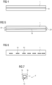
- FIG 4 shows a plan view of a slot closure 1, which has an opening 19 which extends over the length of the slot closure 19 and is centered.
- the representation according to FIG 7 shows a cross-section of a slotted seal 1.
- the slotted seal 1 has retaining webs 18 and a channel 6.
- the channel 6 has an opening 19 which is designed as a nozzle.
- the opening 19 tapers towards the outlet and thus forms the nozzle.
- the nozzle can be used to better determine the outlet direction of the fluid, for example.
Landscapes
- Engineering & Computer Science (AREA)
- Power Engineering (AREA)
- Motor Or Generator Cooling System (AREA)
Description
- Die Erfindung betrifft einen Nutverschluss einer elektrischen Maschine, sowie auch eine elektrische Maschine. Das Dokument
US2009127967 offenbart eine entsprechende elektrische Maschine des Standes der Technik. - Die Erfindung betrifft weiterhin ein Verfahren zur Kühlung einer elektrischen Maschine und/oder ein Verfahren zur Simulation eines Betriebs der elektrischen Maschine. Des Weiteren betrifft die Erfindung ein Computerprogramm zur Durchführung eines der Verfahren, insbesondere bei Ablauf in einer Steuereinheit.
- Eine elektrische Maschine ist beispielsweise ein Motor oder ein Generator. Elektrische Maschinen können Synchronmaschinen oder Asynchronmaschinen sein. Die elektrische Maschine weist elektrische Leiter in einem Aktivteil aus. Das Aktivteil ist beispielsweise ein Stator und/oder ein Läufer der elektrischen Maschine. Die elektrischen Leiter können in Nuten positioniert sein, wobei die Nuten mittels eines Nutverschlusses verschließbar sind.
- Beim Betrieb der elektrischen Maschine entstehen Verluste. Verluste werden in derartigen elektrischen rotierenden Maschinen, beispielsweise Motoren und Generatoren, insbesondere in stromdurchflossenen Wicklungen, Dynamoblechkörpern und massiven Eisenteilen, in Wärme umgesetzt. Die Maschinenbauteile werden erwärmt. Um der Erwärmung entgegenzuwirken kann eine Kühlung durchgeführt werden. Zweck einer Maschinenkühlung ist insbesondere das Abführen der auftretenden Verlustwärmeströme an die Umgebung, um Bauteiltemperaturgrenzen nicht zu überschreiten. Darüber hinaus beeinflussen die Kühlung bzw. die sich einstellenden Betriebstemperaturen den Maschinenwirkungsgrad, die Maschinenausnutzung, die Fertigungskosten und/oder gegebenenfalls, insbesondere bei permanenterregten Maschinen, die Materialkosten. Es gibt offene und geschlossene Kühlkreisläufe. Das Kühlfluid kann beispielsweise gasförmig (z.B. Luft) oder flüssig (z.B. Wasser) sein. Ferner werden insbesondere durch die Wahl des Kühlverfahrens bei geschlossenem Kühlkreislauf die Größe des Rückkühlwerks, die volumetrische und gravimetrische Leistungsdichte und die Kosten der gesamten Maschine, insbesondere des Rückkühlwerks, skaliert. Die fortschreitende Drehmomenten- bzw. Leistungsdichte-steigerung von elektrischen Maschinen, insbesondere von elektrischen Großmaschinen mit Nennleistungen im Megawattbereich (z.B. 1 bis 90 MW), wird vorrangig durch kühltechnische Maßnahmen begrenzt, da die Volumina der Verlustquellen kubisch, deren wärmeabführende Flächen jedoch nur quadratisch ansteigen.
- Eine Aufgabe der Erfindung ist es die Kühlung einer elektrischen Maschine zu verbessern.
- Eine Lösung der Aufgabe gelingt bei einem Nutverschluss nach Anspruch 1, bei einem Verfahren nach Anspruch 7 bzw. bei einem Computerprogrammprodukt nach Anspruch 12.
- Ein Nutverschluss dient zum Verschließen einer Nut eines Aktivteils einer elektrischen Maschine. Der Nutverschluss weist einen Kanal zur Führung eines Fluids auf. Damit weist eine elektrische Maschine Nuten auf, wobei die Nuten jeweils einen Luftverschluss aufweisen, wobei der Nutverschluss einen Kanal zur Führung eines Fluids aufweist. Das Fluid ist beispielsweise gasförmig (zum Beispiel Luft) oder flüssig (zum Beispiel Wasser). So sind verschiedene Konzepte für die elektrische Maschine unter Einbeziehung einer Verdampfung oder ohne Verdampfung realisierbar. Es ist beispielsweise möglich als Fluid Gase wie Helium oder Wasserstoff zu verwenden. Dies kann insbesondere bei Drücken über dem Umgebungsdruck geschehen. So können insbesondere im Vergleich mit Luft günstigere Wärmekapazitäten und Wärmeübergangskoeffizienten bei gleichzeitig geringeren Ventilationsverlusten genutzt werden. Darüber hinaus können als Fluid neben Wasser z.B. auch Öle, wie z.B. Silikonöle oder Ester, Polyfluorierte Alkylverbindungen, etc., verwendet werden.
- Das Fluid ist in einem offenen Kühlkreislauf und/oder in einem geschlossenen Kühlkreislauf geführt. So kann das Fluid beispielsweise über einen Wärmetauscher geführt werden, der die von dem Fluid aufgenommene Wärme z.B. an Luft abgibt. Hierfür ist insbesondere ein Lüfter vorzusehen, wobei auch eine lüfterlose Ausführung möglich ist. Durch die Erfindung können insbesondere verschiedenste Kühlkonzepte verbessert werden. So können in einer Ausgestaltung eines Kühlkonzeptes auch Bauteile mit einer inhärenten Wärmeentwicklung, die in direktem Kontakt mit Luft (Kühlluft) sind, in einem geschlossenen Kreislauf (insbesondere also einem geschlossenen Luftkreislauf) gekühlt sein und die dabei von der Luft aufgenommene Wärme in der Folge in einem Luft-Wasser- oder Luft-Luft-Wärmeübertrager (Wärmetauscher) an die Umgebung abgegeben wird, ohne die Systemkomplexität signifikant zu erhöhen.
- In einer Ausgestaltung des Nutverschlusses weist dieser eine Vielzahl von Kanälen auf. Dadurch kann beispielsweise eine Rückleitung des Fluids durchgeführt werden. Dies kann auch zum Ausgleich der Temperaturverteilung über die Nut durch das Fluid dienen.
- In einer Ausgestaltung des Nutverschlusses weist der Nutverschluss eine Öffnung auf, wobei die Öffnung den Kanal zum Luftspalt der elektrischen Maschine (hin) öffnet. Dadurch kann Fluid zu einer verstärkten Kühlung austreten. Entspannt sich das Fluid (Gas) beim Austritt, so kann eine zusätzliche Kühlung erreicht werden.
- In einer Ausgestaltung des Nutverschlusses weist die Öffnung eine Düse auf bzw. ist die Öffnung als eine Düse ausgestaltet. Durch die Düse, bzw. durch Düsen ist eine Richtung der austretenden Luft vorgebbar. Auch zum Entspannen eines Gases ist die Verwendung eine Düse geeignet.
- In einer Ausgestaltung des Nutverschlusses weist in dieser eine Oberfläche auf welche dreidimensional ausgeführt ist, um eine Oberflächenvergrößerung der Oberfläche zu erreichen, welche im Einbauzustand des Nutverschlusses in die elektrische Maschine zum Luftspalt hin gerichtet ist. Dies verbessert die Wärmeabfuhr.
- Eine elektrische Maschine weist eine Nut in einem Aktivteil der elektrischen Maschine auf. Insbesondere weist eine elektrische Maschine eine Vielzahl von Nuten auf, wobei in den Nuten des Aktivteils der elektrischen Maschine elektrische Wicklungen gelegt sind. Die Nut bzw. die Nuten sind mit einem Nutverschluss verschlossen. Die Ausgestaltung des Nutverschlusses ist hier in verschiedenen Variationen beschrieben. Der Nutverschluss bzw. die Nutverschlüsse weisen einen oder mehrere Kanäle auf. Die elektrische Maschine kann beispielsweise nur Nutverschlüsse mit Kanälen aufweisen oder auch eine Mischung aus Nutverschlüssen mit und ohne einen Kanal. Dies hängt beispielsweise von der erforderlichen Kühlleistung ab.
- In einer Ausgestaltung der elektrischen Maschine weist ein Nutverschluss einen Kanal oder eine Vielzahl von Kanälen auf. Weiterhin weist in einer Ausgestaltung der elektrischen Maschine diese nur Nutverschlüsse mit jeweils einem Kanal auf. In einer weiteren Ausgestaltung der elektrischen Maschine weist diese Nutverschlüsse mit jeweils zumindest zwei Kanälen auf. In einer weiteren Ausgestaltung der elektrischen Maschine weisen diese Nutverschlüsse eine unterschiedliche Anzahl von Kanälen auf. Es können sich über den Umfang der elektrischen Maschine also Nutverschlüsse mit einer unterschiedlichen Anzahl von Kanälen abwechseln bzw. anschließen. Derart kann auf unterschiedliche Kühlungserfordernisse der elektrischen Maschine flexibel eingegangen werden.
- Der Nutverschluss kann eine Keilform aufweisen. Deswegen kann der Nutverschluss auch als Nutverschlusskeil bezeichnet werden. Der Nutverschluss verschließt in Nuten eines Aktivteils der elektrischen Maschine. Das Aktivteil der elektrischen Maschine ist ein Stator und/oder ein Läufer der elektrischen Maschine.
- In einer Ausgestaltung der elektrischen Maschine ist der Kanal im Nutverschluss und/oder der Nutverschluss in der gleichen radialen Position, wie ein Streusteg. Dadurch ergibt sich z.B. eine kompakte Bauweise.
- In einer Ausgestaltung der elektrischen Maschine weist der der Nutverschluss eine erste Oberfläche auf, welche der Nut, bzw. dem Nutgrund, zugewandt ist und eine zweite Oberfläche auf, welche der Nut, bzw. dem Nutgrund, abgewandt ist, wobei die zweite Oberfläche mehr Wärmeenergie abgeben kann, als die erste Oberfläche, wobei die zweite Oberfläche zum Luftspalt der elektrischen Maschine gerichtet ist. So wird mehr Wärmeenergie zum Luftspalt geleitet. Durch den Luftspalt kann ein Kühlfluid wie Luft oder Wasser geführt sein. Die zweite Oberfläche weist beispielsweise eine größere Oberflächenrauigkeit auf als die erste Oberfläche. Damit kann die zweite Oberfläche größer ausgeführt werden als die erste Oberfläche. Die zweite Oberfläche kann beispielsweise auch eine Wellenform, Zackenform oder Kammform aufweisen, wobei sich durch diese Formen eine Oberflächenvergrößerung im Vergleich zu einer zweidimensionalen flachen Oberfläche ergibt.
- In einer Ausgestaltung der elektrischen Maschine sind die Nutverschlusskeile, welche zum Fixieren der Wicklung in der Nut dienen, mit innenliegenden Kanälen (≥ 1) ausgestaltet, damit sie mit einem Kühlmedium (Fluid) durchströmt werden können. Die gekühlten Keile stellen somit eine Wärmesenke dar, die sich in unmittelbarer Umgebung zur Wärmequelle (stromdurchflossene Leiter) befindet und somit die Spulen und die Zähne kühlen. Zudem wird das im Luftspalt strömende, insbesondere gasförmige Kühlmedium an der Außenseite des Keils ebenso gekühlt. Diese Oberfläche kann so gestaltet werden, dass die Wärmeübertragungsfläche maximal wird (z.B. durch hohe Oberflächenrauheit). Da sich der Querschnitt der gekühlten Nutverschlusskeile erhöhen wird, ist dieser vorteilhaft im Bereich des Streustegs ausgeprägt bzw. ausgeführt. Für Kühlkonzepte die einen Phasenwechsel nutzen, um die Kühlleistung zu erhöhen, kann mindestens ein Keil so gestaltet werden, dass er in definierten Abständen Öffnungen in Richtung des Luftspalts hat, durch die das Kühlmedium austreten kann. Optional können die Öffnungen eine Düsengeometrie aufweisen. Dadurch kann das Kühlmedium direkt auf den Läufer gesprüht werden, um diesen ebenfalls zu kühlen. Um die elektromagnetischen Eigenschaften der Maschine nicht zu beeinflussen, ist vorteilhaft auf die Materialwahl der Keile zu achten.
- Gemäß eines Verfahrens zur Kühlung einer elektrischen Maschine, wobei die elektrische Maschine Nuten aufweist, wobei die Nuten mit Nutverschlüssen verschlossen sind, wobei zumindest ein Nutverschlusskeil einen Kanal aufweist, wird durch den Kanal ein Fluid zur Kühlung der elektrischen Maschine geführt. So ist das Kühlmedium (Fluid) nahe dem Bereich der elektrischen Maschine, der zur Erwärmung der elektrischen Maschine führt. Derart ist eine effiziente Kühlung der elektrischen Maschine möglich.
- Gemäß einer Ausgestaltung des Verfahrens kann ein Nutverschluss gemäß einer der beschriebenen Ausführungsformen verwendet werden.
- Gemäß einer Ausgestaltung des Verfahrens wird das Fluid in den Luftspalt der elektrischen Maschine geführt und insbesondere auf den Läufer der elektrischen Maschine gesprüht bzw. geleitet. So kann die Kühlwirkung noch weiter verstärkt werden. Das Sprühen bzw. Leiten des Fluids auf den Läufer wird beispielsweise durch Löcher, Schlitze, offene Poren und/oder Düsen im Kanal bzw. Nutverschluss ermöglicht.
- In einer Ausgestaltung des Verfahrens wird zur Kühlung der elektrischen Maschine ein Phasenwechsel des Fluids verwendet. So kann beispielsweise ein flüssiges Fluid verdampft werden, um die Kühlwirkung zu verbessern. In einer weiteren Ausgestaltung des Verfahrens kann ein gasförmiges Fluids entspannt werden. Das Fluids weist also zunächst einen ersten Druck auf und nach der Entspannung einen zweiten Druck, wobei der erste Druck höher ist als der zweite Druck. Auch durch die Entspannung des gasförmigen Fluids kann eine Kühlwirkung erzielt werden.
- In einer Ausgestaltung des Verfahrens wird dieses Verfahren simuliert. So kann beispielsweise die Kühlung einer elektrischen Maschine simuliert werden. Damit kann beispielsweise auch der Betrieb der elektrischen Maschine simuliert werden und insbesondere auch den Betriebszustände abhängig von der abverlangten Leistung.
- In einer Ausgestaltung des Verfahrens betrifft das Verfahren also den simulierten Betrieb. Es wird beispielsweise der Betrieb der elektrischen Maschine in einer Windkraftanlage bzw. einer Maschineneinrichtung simuliert. Dadurch kann beispielsweise die Auslegung der Windkraftanlage bzw. der Maschineneinrichtung verbessert werden. Die Maschineneinrichtung ist beispielsweise eine Pumpeinrichtung, eine Kompressoreinrichtung (Kompressor), eine Elektrolokomotive oder dergleichen. Durch die Simulation ist auch die Ausbildung eines digitalen Zwillings möglich. So kann beispielsweise parallel zum Betrieb der elektrischen Maschine eine Überwachung erfolgen, um beispielsweise eine noch abrufbare Spitzenleistung für eine gewisse Zeit zu berechnen und/oder um einen sich anbahnenden Fehler zu erkennen.
- Es ist ein Computerprogrammprodukt vorsehbar, das computerausführbare Programmmittel aufweist und bei Ausführung auf einer Rechnereinrichtung mit Prozessormitteln und Datenspeichermitteln geeignet ist, ein Verfahren nach einer der beschriebenen Arten durchzuführen. So kann eine zugrundeliegende Aufgabenstellung durch ein Computerprogrammprodukt gelöst werden, das zu einem Simulieren eines Betriebsverhaltens der elektrischen Maschine ausgebildet ist. Dazu kann das Computerprogrammprodukt Daten der elektrischen Maschine umfassen. Das Computerprogrammprodukt kann auch eine Datenschnittstelle aufweisen, über die Betriebsparameter, wie beispielsweise eine Drehzahl, ein Motorstrom und/oder eine Temperatur vorgebbar bzw. einspielbar sind. Ebenso kann das Computerprogrammprodukt auch eine Datenschnittstelle zum Ausgeben von Simulationsergebnissen aufweisen. Die elektrische Maschine, deren Betriebsverhalten mittels des Computerprogrammprodukts simulierbar ist, ist insbesondere gemäß mindestens einer der skizzierten Ausführungsformen ausgebildet. Das Computerprogrammprodukt kann dazu beispielsweise als sogenannter Digitaler Zwilling ausgebildet sein.
- Ein Computerprogrammprodukt bzw. das Computerprogrammprodukt weist also computerausführbare Programmmittel auf und ist zur Ausführung auf einer Rechnereinrichtung mit Prozessormitteln und Datenspeichermitteln geeignet, um zumindest eines der beschriebenen Verfahren zumindest eine der beschriebenen elektrischen Maschinen zu simulieren.
- Im Folgenden ist die Erfindung mit Hilfe von schematischen Ausführungsbeispielen weiter beschrieben. Gleichartige Elemente sind dabei mit den gleichen Bezugszeichen versehen.
- Hierzu zeigt:
- FIG 1
- einen Längsschnitt durch eine elektrische Maschine,
- FIG 2
- einen Schnitt durch die elektrische Maschine von
FIG 1 gemäß einer Linie II-II inFIG 1 , - FIG 3
- einen weiteren Schnitt durch eine elektrische Maschine,
- FIG 4
- eine Aufsicht auf einen Nutverschluss,
- FIG 5
- eine weitere Aufsicht auf einen Nutverschluss,
- FIG 6
- eine weitere Aufsicht auf einen Nutverschluss und
- FIG 7
- einen Querschnitt eines Nutverschlusses.
-
FIG 1 zeigt einen Längsschnitt durch eine elektrische Maschine 10. GemäßFIG 1 weist die rotatorische elektrische Maschine 10 einen Rotor 2 (auch Läufer genannt) und ein Stator 3 mit einem Statorblechpaket und Wickelköpfen 4 auf. Der Rotor 2 ist auf einer Rotorwelle 14 angeordnet. Die Rotorwelle 14 ist in Lagern 15 gelagert, so dass die Rotorwelle 14 um eine Rotationsachse 16 rotierbar ist. - Soweit die Begriffe "axial", "radial" und "tangential verwendet werden, bedeutet "axial" eine Richtung parallel zur Rotationsachse 16. "Radial" ist eine Richtung orthogonal zur Axialrichtung direkt auf die Rotationsachse 6 zu bzw. von ihr weg. "Tangential" ist eine Richtung, die sowohl orthogonal zur Axialrichtung als auch orthogonal zur Radialrichtung gerichtet ist. Tangential ist also eine Richtung, die bei einer konstanten Axialposition und in einem konstanten radialen Abstand von der Rotationsachse 16 kreisförmig um die Rotationsachse 6 herum gerichtet ist.
- Das Statorblechpaket weist Statorbleche 13 auf. Das Statorblechpaket weist Nuten 12 auf. Diese Nuten 12 sind Statornuten und verlaufen parallel zur Rotationsachse 16 der elektrischen Maschine 10. Sie sind kreisförmig um die Rotationsachse 16 herum verteilt angeordnet (siehe
FIG 2 ). -
FIG 2 zeigt einen Schnitt durch die elektrische Maschine vonFIG 1 gemäß einer Linie II-II inFIG 1 mit einem Statorblechpaket 11. Die Statornuten 12 sind zur Rotationsachse 16 hin - also nach radial innen hin - zunächst offen. In den Statornuten 12 sind die Wicklungen 9 eines Statorwicklungssystems angeordnet. In den Statornuten 12 sind die Hauptabschnitte der Wicklungen 9 angeordnet. Wicklungsköpfe 4 der Wicklungen 9 ragen, wie allgemein üblich, gemäßFIG 1 an den beiden axialen Enden des Statorblechpakets über das Statorblechpaket 3 hinaus. Die Nuten 12 sind durch Nutverschlüsse 1 verschlossen, wobei die Nutverschlüsse 1 jeweils einen Kanal 6 aufweisen. -
FIG 3 zeigt einen weiteren Schnitt durch eine elektrische Maschine mit einem Stator 2 und einem Rotor 3. Gezeigt sind Zähne 8 durch welche die Nuten 12 ausgebildet sind. Die Zähne 8 weisen einen Streusteg 7 auf. Die Wicklungen 9 sind in der Nut 12 von den Zähnen 8 durch eine Isolierung 5 isoliert. Die Zähne 8 weisen Rillen 17 auf. In diese Rillen 17 können Haltestege 18 der Nutverschlüsse 1,1' eingreifen. Beispielhaft sind in derFigur 3 zwei Nutverschlüsse 1 eingezeichnet. Die Nutverschlüsse 1 weisen neben Haltestegen 18 auch jeweils einen Kanal 6 auf. Der Kanal 6 des Nutverschlusses 1` weist eine Öffnung 19 auf. Aus dieser Öffnung 19 kann Fluid 20 in den Luftspalt 21 austreten. Durch das Fluid 20 im Kanal 6 kann Wärmeenergie Q', welche durch einen Pfeil 22 als Wärmefluss symbolisiert ist, aus den Zähnen bzw. dem Stator ausgeführt, also abgeführt werden. Der Nutverschluss 1 weist eine erste Oberfläche 24 und eine zweite Oberfläche 25. Die erste Oberfläche 24 ist im Vergleich zur zweiten Oberfläche 25 glatter. Die zweite Oberfläche 25 ist also größer als die erste Oberfläche 24 und kann damit bezüglich der Oberflächenstruktur mehr Wärmeenergie abgeben. - Die Darstellung nach
FIG 4 zeigt eine Aufsicht auf einen Nutverschluss 1, welcher eine Öffnung 19 aufweist, welche sich über die Länge des Nutverschlusses 19 erstreckt und zentriert ist. - Die Darstellung nach
FIG 5 zeigt eine weitere Aufsicht auf einen Nutverschluss 1, welcher eine Öffnung 19 aufweist, der Breite 23, 23` sich verändert. Dadurch kann die Austrittsmenge des Fluids über die Länge angepasst werden. - Die Darstellung nach
FIG 6 zeigt eine weitere Aufsicht auf einen Nutverschluss 1, mit einer Vielzahl von Öffnungen 19, welche einen unterschiedlichen Abstand voneinander aufweisen. Auch dadurch kann die Austrittsmenge des Fluids über die Länge angepasst werden. - Die Darstellung nach
FIG 7 zeigt einen Querschnitt eines Nutverschlusses 1. Der Nutverschluss 1 weist Haltestege 18 und einen Kanal 6 auf. Der Kanal 6 weist eine Öffnung 19 auf welche als Düse ausgeführt ist. Die Öffnung 19 verjüngt sich zum Austritt hin und bildet so die Düse. Durch die Düse kann beispielsweise die Austrittrichtung des Fluids besser bestimmt werden.
Claims (8)
- Elektrische Maschine (5) welche eine Nut (12) in einem Aktivteil (2,3) aufweist, wobei die Nut (12) mit einem Nutverschluss (1,1') verschlossen ist, wobei der Nutverschluss einen Kanal (6) zur Führung eines Fluids (20) aufweist, wobei der Nutverschluss (1,1') eine Öffnung (19) aufweist, wobei die Öffnung (19) den Kanal (6) zu einem Luftspalt (21) hin öffnet, wobei die Öffnung (19) eine Düse ist, wobei ein Phasenwechsel des Fluids nutzbar ist.
- Elektrische Maschine (10) nach Anspruch 1, wobei der Kanal (6) in der gleichen radialen Position ist wie ein Streusteg (7) .
- Elektrische Maschine (10) nach Anspruch 1 oder 2, wobei der Nutverschluss (1,1') eine erste Oberfläche (24) aufweist, welche der Nut (12) zugewandt ist und eine zweite Oberfläche (25) aufweist, welche der Nut (12) abgewandt ist, wobei die zweite Oberfläche (25) mehr Wärmeenergie abgeben kann als die erste Oberfläche (24), wobei die zweite Oberfläche (25) zum Luftspalt (21) der elektrischen Maschine (10) gerichtet ist.
- Verfahren zur Kühlung einer elektrischen Maschine (10), wobei die elektrische Maschine (10) Nuten (12) aufweist, wobei die Nuten (12) mit Nutverschlüssen (1,1') verschlossen sind, wobei zumindest ein Nutverschluss (1,1') einen Kanal (6) aufweist, wobei durch den Kanal (6) ein Fluid (20) zur Kühlung der elektrischen Maschine (10) geführt wird, wobei der Nutverschluss (1,1') eine Öffnung (19) aufweist, wobei die Öffnung (19) den Kanal (6) zu einem Luftspalt (21) hin öffnet, wobei die Öffnung (19) eine Düse ist, wobei zur Kühlung der elektrischen Maschine (10) ein Phasenwechsel des Fluids (20) verwendet wird.
- Verfahren nach Anspruch 4, wobei eine elektrische Maschine (10) nach einem der Ansprüche 1 bis 3 verwendet wird.
- Verfahren nach Anspruch 4 oder 5, wobei das Fluid (20) in den Luftspalt (21) der elektrischen Maschine (10) geführt wird und insbesondere auf den Läufer (2) gesprüht wird.
- Verfahren nach einem der Ansprüche 4 bis 6, wobei das Verfahren simuliert wird.
- Computerprogrammprodukt, das computerausführbare Programmmittel aufweist und bei Ausführung auf einer Rechnereinrichtung mit Prozessormitteln und Datenspeichermitteln geeignet ist, ein Verfahren nach einem der Ansprüche 4 bis 7 durchzuführen und/oder eine elektrische Maschine (10) nach einem der Ansprüche 1 bis 3 zu simulieren.
Applications Claiming Priority (2)
| Application Number | Priority Date | Filing Date | Title |
|---|---|---|---|
| EP20199131.2A EP3979469B1 (de) | 2020-09-30 | 2020-09-30 | Nutverschluss für eine elektrische maschine |
| PCT/EP2021/076574 WO2022069432A1 (de) | 2020-09-30 | 2021-09-28 | Nutverschluss für eine elektrische maschine |
Publications (2)
| Publication Number | Publication Date |
|---|---|
| EP4193452A1 EP4193452A1 (de) | 2023-06-14 |
| EP4193452B1 true EP4193452B1 (de) | 2024-07-10 |
Family
ID=72709011
Family Applications (2)
| Application Number | Title | Priority Date | Filing Date |
|---|---|---|---|
| EP20199131.2A Active EP3979469B1 (de) | 2020-09-30 | 2020-09-30 | Nutverschluss für eine elektrische maschine |
| EP21786793.6A Active EP4193452B1 (de) | 2020-09-30 | 2021-09-28 | Nutverschluss für eine elektrische maschine |
Family Applications Before (1)
| Application Number | Title | Priority Date | Filing Date |
|---|---|---|---|
| EP20199131.2A Active EP3979469B1 (de) | 2020-09-30 | 2020-09-30 | Nutverschluss für eine elektrische maschine |
Country Status (4)
| Country | Link |
|---|---|
| US (1) | US20230291262A1 (de) |
| EP (2) | EP3979469B1 (de) |
| CN (1) | CN116235387A (de) |
| WO (1) | WO2022069432A1 (de) |
Families Citing this family (1)
| Publication number | Priority date | Publication date | Assignee | Title |
|---|---|---|---|---|
| DE102023123041A1 (de) * | 2023-08-28 | 2025-03-06 | Schaeffler Technologies AG & Co. KG | Lamelle zum Einbringen eines Nutverschlusselements in eine Statornut eines Stators einer elektrischen Maschine, Vorrichtung und Verfahren zum Einbringen von Nutverschlusselementen in jeweils eine zugewiesene Statornut |
Citations (2)
| Publication number | Priority date | Publication date | Assignee | Title |
|---|---|---|---|---|
| US6113024A (en) * | 1999-04-30 | 2000-09-05 | Alliedsignal Inc. | Winding wedge retention to maintain coil form |
| EP3509193A1 (de) * | 2018-01-04 | 2019-07-10 | Hamilton Sundstrand Corporation | Flüssigkeitsgekühlter polkeil |
Family Cites Families (8)
| Publication number | Priority date | Publication date | Assignee | Title |
|---|---|---|---|---|
| GB817512A (en) * | 1955-02-18 | 1959-07-29 | English Electric Co Ltd | Improvements relating to dynamo-electric machines |
| US2945139A (en) * | 1957-11-15 | 1960-07-12 | Gen Motors Corp | Method and wedges for conducting heat from slots of dynamoelectric machine |
| US3995180A (en) * | 1975-03-10 | 1976-11-30 | General Electric Company | Generator rotor outlets for increased ventilation |
| US4409502A (en) * | 1981-12-17 | 1983-10-11 | Westinghouse Electric Corp. | Self-cooled electrical machine with integrated fan and salient pole rotor |
| US6791230B2 (en) * | 2001-09-07 | 2004-09-14 | Honeywell International, Inc. | System and method for retaining wedges in a rotor |
| US7936103B2 (en) * | 2007-11-21 | 2011-05-03 | General Electric Company | Methods for fabricating a wedge system for an electric machine |
| DE102010042175A1 (de) * | 2010-10-07 | 2012-04-26 | BSH Bosch und Siemens Hausgeräte GmbH | Elektrische Maschine mit Nutkeilen |
| CN109787387B (zh) * | 2019-01-29 | 2020-09-15 | 北京金风科创风电设备有限公司 | 风力发电机组、电动汽车、电机、转子、热沉式永磁磁极紧固结构、加工、散热和降低扭振方法 |
-
2020
- 2020-09-30 EP EP20199131.2A patent/EP3979469B1/de active Active
-
2021
- 2021-09-28 EP EP21786793.6A patent/EP4193452B1/de active Active
- 2021-09-28 US US18/029,322 patent/US20230291262A1/en not_active Abandoned
- 2021-09-28 WO PCT/EP2021/076574 patent/WO2022069432A1/de not_active Ceased
- 2021-09-28 CN CN202180067008.8A patent/CN116235387A/zh active Pending
Patent Citations (2)
| Publication number | Priority date | Publication date | Assignee | Title |
|---|---|---|---|---|
| US6113024A (en) * | 1999-04-30 | 2000-09-05 | Alliedsignal Inc. | Winding wedge retention to maintain coil form |
| EP3509193A1 (de) * | 2018-01-04 | 2019-07-10 | Hamilton Sundstrand Corporation | Flüssigkeitsgekühlter polkeil |
Also Published As
| Publication number | Publication date |
|---|---|
| CN116235387A (zh) | 2023-06-06 |
| EP3979469B1 (de) | 2026-04-01 |
| EP3979469A1 (de) | 2022-04-06 |
| WO2022069432A1 (de) | 2022-04-07 |
| EP4193452A1 (de) | 2023-06-14 |
| US20230291262A1 (en) | 2023-09-14 |
Similar Documents
| Publication | Publication Date | Title |
|---|---|---|
| DE69838316T2 (de) | Direktgekühlter Dynamoelektrishermaschinestäderkern mit erhöhter Wärmeübertragungsfähigkeit | |
| EP2580848B1 (de) | Dynamoelektrische maschine mit luft-flüssigkeitskühlung | |
| EP2933902B1 (de) | Entwärmung einer elektrischen Maschine | |
| EP4193450B1 (de) | Windkraftanlage mit zumindest einer dynamoelektrischen maschine | |
| WO2015124360A2 (de) | Kühlung einer elektrischen maschine | |
| DE2608291A1 (de) | Gasgekuehlter generator-rotor mit erhoehter ventilation | |
| EP2812984A2 (de) | Elektrische maschine mit phasentrenner | |
| DE19919040C2 (de) | Synchronmaschine oder Asychronmaschine für große Windenergieanlagen | |
| EP3033825B1 (de) | Einrichtung zum ablenken von zumindest einem teil eines axial in einem zwischen einem rotor und einem stator einer rotierenden elektrischen maschine angeordneten zwischenraum strömenden kühlfluids | |
| EP3979469B1 (de) | Nutverschluss für eine elektrische maschine | |
| WO2014005910A2 (de) | Elektromaschine mit einem mit wirbelgeneratoren versehenen stator-lamellenpaket für eine integrierte kühlanordnung | |
| DE102008002299A1 (de) | Rotor mit innengekühlter Rotorwicklung | |
| DE102020105790A1 (de) | Kühlkonzept zur Schleuderkühlung von elektrischen Maschinen über ein Phasenwechselmaterial (PCM) | |
| DE19753320A1 (de) | Verfahren zur Kühlung einer Wechselstrommaschine, insbesondere Transversalflußmaschine und Wechselstrommaschine | |
| EP2120314A1 (de) | Rotorkühlung für eine dynamoelektrische Maschine | |
| Wu et al. | Study on the suppression effect of variable hydrogen parameters on the temperature rise of the turbo‐generator rotor under deep peak regulation | |
| Huang et al. | Analysis and optimization of oil cooling structure for electric vehicle power motor | |
| Mao et al. | Temperature analysis of waveform water channel for high-power permanent magnet synchronous motor | |
| EP2112746A1 (de) | Dynamoelektrische Maschine | |
| DE19731313B4 (de) | Großer Synchronmotor mit veränderbarer Drehzahl | |
| EP2911276A1 (de) | Kühlkreislauf mit mindestens zwei Kühlmitteln für elektrische Maschine | |
| DE112021003084T5 (de) | Elektrische rotationsmaschine | |
| DE10052427A1 (de) | Schnelllaufende elektrische Maschine | |
| EP2112745A1 (de) | Verfahren zur Kühlung eines elektrischen Leiters | |
| EP0848478A1 (de) | Verfahren zur Kühlung einer Wechselstrommaschine, insbesondere Transversalflussmaschine |
Legal Events
| Date | Code | Title | Description |
|---|---|---|---|
| STAA | Information on the status of an ep patent application or granted ep patent |
Free format text: STATUS: UNKNOWN |
|
| STAA | Information on the status of an ep patent application or granted ep patent |
Free format text: STATUS: THE INTERNATIONAL PUBLICATION HAS BEEN MADE |
|
| PUAI | Public reference made under article 153(3) epc to a published international application that has entered the european phase |
Free format text: ORIGINAL CODE: 0009012 |
|
| STAA | Information on the status of an ep patent application or granted ep patent |
Free format text: STATUS: REQUEST FOR EXAMINATION WAS MADE |
|
| 17P | Request for examination filed |
Effective date: 20230310 |
|
| AK | Designated contracting states |
Kind code of ref document: A1 Designated state(s): AL AT BE BG CH CY CZ DE DK EE ES FI FR GB GR HR HU IE IS IT LI LT LU LV MC MK MT NL NO PL PT RO RS SE SI SK SM TR |
|
| DAV | Request for validation of the european patent (deleted) | ||
| DAX | Request for extension of the european patent (deleted) | ||
| RIC1 | Information provided on ipc code assigned before grant |
Ipc: H02K 3/24 20060101ALI20231124BHEP Ipc: H02K 9/20 20060101ALI20231124BHEP Ipc: H02K 5/20 20060101ALI20231124BHEP Ipc: H02K 3/487 20060101AFI20231124BHEP |
|
| RAP1 | Party data changed (applicant data changed or rights of an application transferred) |
Owner name: INNOMOTICS GMBH |
|
| GRAP | Despatch of communication of intention to grant a patent |
Free format text: ORIGINAL CODE: EPIDOSNIGR1 |
|
| STAA | Information on the status of an ep patent application or granted ep patent |
Free format text: STATUS: GRANT OF PATENT IS INTENDED |
|
| INTG | Intention to grant announced |
Effective date: 20240119 |
|
| GRAS | Grant fee paid |
Free format text: ORIGINAL CODE: EPIDOSNIGR3 |
|
| GRAA | (expected) grant |
Free format text: ORIGINAL CODE: 0009210 |
|
| STAA | Information on the status of an ep patent application or granted ep patent |
Free format text: STATUS: THE PATENT HAS BEEN GRANTED |
|
| AK | Designated contracting states |
Kind code of ref document: B1 Designated state(s): AL AT BE BG CH CY CZ DE DK EE ES FI FR GB GR HR HU IE IS IT LI LT LU LV MC MK MT NL NO PL PT RO RS SE SI SK SM TR |
|
| REG | Reference to a national code |
Ref country code: CH Ref legal event code: EP |
|
| REG | Reference to a national code |
Ref country code: DE Ref legal event code: R096 Ref document number: 502021004346 Country of ref document: DE |
|
| REG | Reference to a national code |
Ref country code: LT Ref legal event code: MG9D |
|
| REG | Reference to a national code |
Ref country code: NL Ref legal event code: MP Effective date: 20240710 |
|
| PG25 | Lapsed in a contracting state [announced via postgrant information from national office to epo] |
Ref country code: PT Free format text: LAPSE BECAUSE OF FAILURE TO SUBMIT A TRANSLATION OF THE DESCRIPTION OR TO PAY THE FEE WITHIN THE PRESCRIBED TIME-LIMIT Effective date: 20241111 |
|
| PG25 | Lapsed in a contracting state [announced via postgrant information from national office to epo] |
Ref country code: NL Free format text: LAPSE BECAUSE OF FAILURE TO SUBMIT A TRANSLATION OF THE DESCRIPTION OR TO PAY THE FEE WITHIN THE PRESCRIBED TIME-LIMIT Effective date: 20240710 |
|
| PG25 | Lapsed in a contracting state [announced via postgrant information from national office to epo] |
Ref country code: PT Free format text: LAPSE BECAUSE OF FAILURE TO SUBMIT A TRANSLATION OF THE DESCRIPTION OR TO PAY THE FEE WITHIN THE PRESCRIBED TIME-LIMIT Effective date: 20241111 Ref country code: NL Free format text: LAPSE BECAUSE OF FAILURE TO SUBMIT A TRANSLATION OF THE DESCRIPTION OR TO PAY THE FEE WITHIN THE PRESCRIBED TIME-LIMIT Effective date: 20240710 |
|
| PG25 | Lapsed in a contracting state [announced via postgrant information from national office to epo] |
Ref country code: NO Free format text: LAPSE BECAUSE OF FAILURE TO SUBMIT A TRANSLATION OF THE DESCRIPTION OR TO PAY THE FEE WITHIN THE PRESCRIBED TIME-LIMIT Effective date: 20241010 |
|
| PG25 | Lapsed in a contracting state [announced via postgrant information from national office to epo] |
Ref country code: GR Free format text: LAPSE BECAUSE OF FAILURE TO SUBMIT A TRANSLATION OF THE DESCRIPTION OR TO PAY THE FEE WITHIN THE PRESCRIBED TIME-LIMIT Effective date: 20241011 Ref country code: FI Free format text: LAPSE BECAUSE OF FAILURE TO SUBMIT A TRANSLATION OF THE DESCRIPTION OR TO PAY THE FEE WITHIN THE PRESCRIBED TIME-LIMIT Effective date: 20240710 Ref country code: PL Free format text: LAPSE BECAUSE OF FAILURE TO SUBMIT A TRANSLATION OF THE DESCRIPTION OR TO PAY THE FEE WITHIN THE PRESCRIBED TIME-LIMIT Effective date: 20240710 |
|
| PG25 | Lapsed in a contracting state [announced via postgrant information from national office to epo] |
Ref country code: BG Free format text: LAPSE BECAUSE OF FAILURE TO SUBMIT A TRANSLATION OF THE DESCRIPTION OR TO PAY THE FEE WITHIN THE PRESCRIBED TIME-LIMIT Effective date: 20240710 |
|
| PG25 | Lapsed in a contracting state [announced via postgrant information from national office to epo] |
Ref country code: LV Free format text: LAPSE BECAUSE OF FAILURE TO SUBMIT A TRANSLATION OF THE DESCRIPTION OR TO PAY THE FEE WITHIN THE PRESCRIBED TIME-LIMIT Effective date: 20240710 |
|
| PG25 | Lapsed in a contracting state [announced via postgrant information from national office to epo] |
Ref country code: IS Free format text: LAPSE BECAUSE OF FAILURE TO SUBMIT A TRANSLATION OF THE DESCRIPTION OR TO PAY THE FEE WITHIN THE PRESCRIBED TIME-LIMIT Effective date: 20241110 |
|
| PG25 | Lapsed in a contracting state [announced via postgrant information from national office to epo] |
Ref country code: HR Free format text: LAPSE BECAUSE OF FAILURE TO SUBMIT A TRANSLATION OF THE DESCRIPTION OR TO PAY THE FEE WITHIN THE PRESCRIBED TIME-LIMIT Effective date: 20240710 |
|
| PG25 | Lapsed in a contracting state [announced via postgrant information from national office to epo] |
Ref country code: ES Free format text: LAPSE BECAUSE OF FAILURE TO SUBMIT A TRANSLATION OF THE DESCRIPTION OR TO PAY THE FEE WITHIN THE PRESCRIBED TIME-LIMIT Effective date: 20240710 Ref country code: RS Free format text: LAPSE BECAUSE OF FAILURE TO SUBMIT A TRANSLATION OF THE DESCRIPTION OR TO PAY THE FEE WITHIN THE PRESCRIBED TIME-LIMIT Effective date: 20241010 |
|
| PG25 | Lapsed in a contracting state [announced via postgrant information from national office to epo] |
Ref country code: RS Free format text: LAPSE BECAUSE OF FAILURE TO SUBMIT A TRANSLATION OF THE DESCRIPTION OR TO PAY THE FEE WITHIN THE PRESCRIBED TIME-LIMIT Effective date: 20241010 Ref country code: PL Free format text: LAPSE BECAUSE OF FAILURE TO SUBMIT A TRANSLATION OF THE DESCRIPTION OR TO PAY THE FEE WITHIN THE PRESCRIBED TIME-LIMIT Effective date: 20240710 Ref country code: NO Free format text: LAPSE BECAUSE OF FAILURE TO SUBMIT A TRANSLATION OF THE DESCRIPTION OR TO PAY THE FEE WITHIN THE PRESCRIBED TIME-LIMIT Effective date: 20241010 Ref country code: LV Free format text: LAPSE BECAUSE OF FAILURE TO SUBMIT A TRANSLATION OF THE DESCRIPTION OR TO PAY THE FEE WITHIN THE PRESCRIBED TIME-LIMIT Effective date: 20240710 Ref country code: IS Free format text: LAPSE BECAUSE OF FAILURE TO SUBMIT A TRANSLATION OF THE DESCRIPTION OR TO PAY THE FEE WITHIN THE PRESCRIBED TIME-LIMIT Effective date: 20241110 Ref country code: HR Free format text: LAPSE BECAUSE OF FAILURE TO SUBMIT A TRANSLATION OF THE DESCRIPTION OR TO PAY THE FEE WITHIN THE PRESCRIBED TIME-LIMIT Effective date: 20240710 Ref country code: GR Free format text: LAPSE BECAUSE OF FAILURE TO SUBMIT A TRANSLATION OF THE DESCRIPTION OR TO PAY THE FEE WITHIN THE PRESCRIBED TIME-LIMIT Effective date: 20241011 Ref country code: FI Free format text: LAPSE BECAUSE OF FAILURE TO SUBMIT A TRANSLATION OF THE DESCRIPTION OR TO PAY THE FEE WITHIN THE PRESCRIBED TIME-LIMIT Effective date: 20240710 Ref country code: ES Free format text: LAPSE BECAUSE OF FAILURE TO SUBMIT A TRANSLATION OF THE DESCRIPTION OR TO PAY THE FEE WITHIN THE PRESCRIBED TIME-LIMIT Effective date: 20240710 Ref country code: BG Free format text: LAPSE BECAUSE OF FAILURE TO SUBMIT A TRANSLATION OF THE DESCRIPTION OR TO PAY THE FEE WITHIN THE PRESCRIBED TIME-LIMIT Effective date: 20240710 |
|
| REG | Reference to a national code |
Ref country code: DE Ref legal event code: R097 Ref document number: 502021004346 Country of ref document: DE |
|
| PG25 | Lapsed in a contracting state [announced via postgrant information from national office to epo] |
Ref country code: RO Free format text: LAPSE BECAUSE OF FAILURE TO SUBMIT A TRANSLATION OF THE DESCRIPTION OR TO PAY THE FEE WITHIN THE PRESCRIBED TIME-LIMIT Effective date: 20240710 Ref country code: SM Free format text: LAPSE BECAUSE OF FAILURE TO SUBMIT A TRANSLATION OF THE DESCRIPTION OR TO PAY THE FEE WITHIN THE PRESCRIBED TIME-LIMIT Effective date: 20240710 Ref country code: DK Free format text: LAPSE BECAUSE OF FAILURE TO SUBMIT A TRANSLATION OF THE DESCRIPTION OR TO PAY THE FEE WITHIN THE PRESCRIBED TIME-LIMIT Effective date: 20240710 |
|
| PG25 | Lapsed in a contracting state [announced via postgrant information from national office to epo] |
Ref country code: EE Free format text: LAPSE BECAUSE OF FAILURE TO SUBMIT A TRANSLATION OF THE DESCRIPTION OR TO PAY THE FEE WITHIN THE PRESCRIBED TIME-LIMIT Effective date: 20240710 Ref country code: MC Free format text: LAPSE BECAUSE OF FAILURE TO SUBMIT A TRANSLATION OF THE DESCRIPTION OR TO PAY THE FEE WITHIN THE PRESCRIBED TIME-LIMIT Effective date: 20240710 |
|
| PG25 | Lapsed in a contracting state [announced via postgrant information from national office to epo] |
Ref country code: CZ Free format text: LAPSE BECAUSE OF FAILURE TO SUBMIT A TRANSLATION OF THE DESCRIPTION OR TO PAY THE FEE WITHIN THE PRESCRIBED TIME-LIMIT Effective date: 20240710 |
|
| PG25 | Lapsed in a contracting state [announced via postgrant information from national office to epo] |
Ref country code: IT Free format text: LAPSE BECAUSE OF FAILURE TO SUBMIT A TRANSLATION OF THE DESCRIPTION OR TO PAY THE FEE WITHIN THE PRESCRIBED TIME-LIMIT Effective date: 20240710 Ref country code: SK Free format text: LAPSE BECAUSE OF FAILURE TO SUBMIT A TRANSLATION OF THE DESCRIPTION OR TO PAY THE FEE WITHIN THE PRESCRIBED TIME-LIMIT Effective date: 20240710 |
|
| REG | Reference to a national code |
Ref country code: CH Ref legal event code: PL |
|
| PLBE | No opposition filed within time limit |
Free format text: ORIGINAL CODE: 0009261 |
|
| STAA | Information on the status of an ep patent application or granted ep patent |
Free format text: STATUS: NO OPPOSITION FILED WITHIN TIME LIMIT |
|
| PG25 | Lapsed in a contracting state [announced via postgrant information from national office to epo] |
Ref country code: LU Free format text: LAPSE BECAUSE OF NON-PAYMENT OF DUE FEES Effective date: 20240928 |
|
| 26N | No opposition filed |
Effective date: 20250411 |
|
| REG | Reference to a national code |
Ref country code: BE Ref legal event code: MM Effective date: 20240930 |
|
| PG25 | Lapsed in a contracting state [announced via postgrant information from national office to epo] |
Ref country code: BE Free format text: LAPSE BECAUSE OF NON-PAYMENT OF DUE FEES Effective date: 20240930 |
|
| PG25 | Lapsed in a contracting state [announced via postgrant information from national office to epo] |
Ref country code: FR Free format text: LAPSE BECAUSE OF NON-PAYMENT OF DUE FEES Effective date: 20240930 |
|
| PG25 | Lapsed in a contracting state [announced via postgrant information from national office to epo] |
Ref country code: CH Free format text: LAPSE BECAUSE OF NON-PAYMENT OF DUE FEES Effective date: 20240930 |
|
| PG25 | Lapsed in a contracting state [announced via postgrant information from national office to epo] |
Ref country code: IE Free format text: LAPSE BECAUSE OF NON-PAYMENT OF DUE FEES Effective date: 20240928 |
|
| REG | Reference to a national code |
Ref country code: DE Ref legal event code: R081 Ref document number: 502021004346 Country of ref document: DE Owner name: INNOMOTICS GMBH, DE Free format text: FORMER OWNER: INNOMOTICS GMBH, MUENCHEN, DE |
|
| PG25 | Lapsed in a contracting state [announced via postgrant information from national office to epo] |
Ref country code: SE Free format text: LAPSE BECAUSE OF FAILURE TO SUBMIT A TRANSLATION OF THE DESCRIPTION OR TO PAY THE FEE WITHIN THE PRESCRIBED TIME-LIMIT Effective date: 20240710 |
|
| PGFP | Annual fee paid to national office [announced via postgrant information from national office to epo] |
Ref country code: DE Payment date: 20250924 Year of fee payment: 5 |
|
| PGFP | Annual fee paid to national office [announced via postgrant information from national office to epo] |
Ref country code: AT Payment date: 20251020 Year of fee payment: 5 |
|
| PG25 | Lapsed in a contracting state [announced via postgrant information from national office to epo] |
Ref country code: CY Free format text: LAPSE BECAUSE OF FAILURE TO SUBMIT A TRANSLATION OF THE DESCRIPTION OR TO PAY THE FEE WITHIN THE PRESCRIBED TIME-LIMIT; INVALID AB INITIO Effective date: 20210928 |
|
| PG25 | Lapsed in a contracting state [announced via postgrant information from national office to epo] |
Ref country code: HU Free format text: LAPSE BECAUSE OF FAILURE TO SUBMIT A TRANSLATION OF THE DESCRIPTION OR TO PAY THE FEE WITHIN THE PRESCRIBED TIME-LIMIT; INVALID AB INITIO Effective date: 20210928 |