EP4193406B1 - Method of operating a fuel cell system, fuel cell system, and vehicle with fuel cell system - Google Patents
Method of operating a fuel cell system, fuel cell system, and vehicle with fuel cell system Download PDFInfo
- Publication number
- EP4193406B1 EP4193406B1 EP22700085.8A EP22700085A EP4193406B1 EP 4193406 B1 EP4193406 B1 EP 4193406B1 EP 22700085 A EP22700085 A EP 22700085A EP 4193406 B1 EP4193406 B1 EP 4193406B1
- Authority
- EP
- European Patent Office
- Prior art keywords
- fuel cell
- cathode
- water
- anode
- fuel
- Prior art date
- Legal status (The legal status is an assumption and is not a legal conclusion. Google has not performed a legal analysis and makes no representation as to the accuracy of the status listed.)
- Active
Links
- 239000000446 fuel Substances 0.000 title claims description 95
- 238000000034 method Methods 0.000 title claims description 15
- XLYOFNOQVPJJNP-UHFFFAOYSA-N water Substances O XLYOFNOQVPJJNP-UHFFFAOYSA-N 0.000 claims description 52
- 239000012528 membrane Substances 0.000 claims description 21
- 239000001257 hydrogen Substances 0.000 claims description 13
- 229910052739 hydrogen Inorganic materials 0.000 claims description 13
- UFHFLCQGNIYNRP-UHFFFAOYSA-N Hydrogen Chemical compound [H][H] UFHFLCQGNIYNRP-UHFFFAOYSA-N 0.000 claims description 11
- 238000000157 electrochemical-induced impedance spectroscopy Methods 0.000 claims description 5
- 238000012544 monitoring process Methods 0.000 claims description 5
- 238000001035 drying Methods 0.000 claims description 3
- 239000007789 gas Substances 0.000 description 14
- 239000001301 oxygen Substances 0.000 description 6
- 229910052760 oxygen Inorganic materials 0.000 description 6
- QVGXLLKOCUKJST-UHFFFAOYSA-N atomic oxygen Chemical compound [O] QVGXLLKOCUKJST-UHFFFAOYSA-N 0.000 description 5
- 238000006243 chemical reaction Methods 0.000 description 3
- 238000009792 diffusion process Methods 0.000 description 3
- 239000000376 reactant Substances 0.000 description 3
- 206010013786 Dry skin Diseases 0.000 description 2
- 238000010521 absorption reaction Methods 0.000 description 2
- 230000001419 dependent effect Effects 0.000 description 2
- 239000007772 electrode material Substances 0.000 description 2
- 239000002828 fuel tank Substances 0.000 description 2
- 230000002427 irreversible effect Effects 0.000 description 2
- 239000000203 mixture Substances 0.000 description 2
- 239000000306 component Substances 0.000 description 1
- 239000002131 composite material Substances 0.000 description 1
- 230000006835 compression Effects 0.000 description 1
- 238000007906 compression Methods 0.000 description 1
- 230000003750 conditioning effect Effects 0.000 description 1
- 239000008358 core component Substances 0.000 description 1
- 238000011161 development Methods 0.000 description 1
- 230000018109 developmental process Effects 0.000 description 1
- 230000000694 effects Effects 0.000 description 1
- 238000006056 electrooxidation reaction Methods 0.000 description 1
- 238000004146 energy storage Methods 0.000 description 1
- 150000002431 hydrogen Chemical class 0.000 description 1
- 125000004435 hydrogen atom Chemical group [H]* 0.000 description 1
- 230000003647 oxidation Effects 0.000 description 1
- 238000007254 oxidation reaction Methods 0.000 description 1
- -1 oxygen anions Chemical class 0.000 description 1
- 239000005518 polymer electrolyte Substances 0.000 description 1
- 230000001105 regulatory effect Effects 0.000 description 1
Images

Classifications
-
- H—ELECTRICITY
- H01—ELECTRIC ELEMENTS
- H01M—PROCESSES OR MEANS, e.g. BATTERIES, FOR THE DIRECT CONVERSION OF CHEMICAL ENERGY INTO ELECTRICAL ENERGY
- H01M8/00—Fuel cells; Manufacture thereof
- H01M8/04—Auxiliary arrangements, e.g. for control of pressure or for circulation of fluids
- H01M8/04082—Arrangements for control of reactant parameters, e.g. pressure or concentration
- H01M8/04089—Arrangements for control of reactant parameters, e.g. pressure or concentration of gaseous reactants
- H01M8/04119—Arrangements for control of reactant parameters, e.g. pressure or concentration of gaseous reactants with simultaneous supply or evacuation of electrolyte; Humidifying or dehumidifying
- H01M8/04156—Arrangements for control of reactant parameters, e.g. pressure or concentration of gaseous reactants with simultaneous supply or evacuation of electrolyte; Humidifying or dehumidifying with product water removal
-
- H—ELECTRICITY
- H01—ELECTRIC ELEMENTS
- H01M—PROCESSES OR MEANS, e.g. BATTERIES, FOR THE DIRECT CONVERSION OF CHEMICAL ENERGY INTO ELECTRICAL ENERGY
- H01M8/00—Fuel cells; Manufacture thereof
- H01M8/04—Auxiliary arrangements, e.g. for control of pressure or for circulation of fluids
- H01M8/04291—Arrangements for managing water in solid electrolyte fuel cell systems
-
- H—ELECTRICITY
- H01—ELECTRIC ELEMENTS
- H01M—PROCESSES OR MEANS, e.g. BATTERIES, FOR THE DIRECT CONVERSION OF CHEMICAL ENERGY INTO ELECTRICAL ENERGY
- H01M8/00—Fuel cells; Manufacture thereof
- H01M8/04—Auxiliary arrangements, e.g. for control of pressure or for circulation of fluids
- H01M8/04298—Processes for controlling fuel cells or fuel cell systems
- H01M8/04313—Processes for controlling fuel cells or fuel cell systems characterised by the detection or assessment of variables; characterised by the detection or assessment of failure or abnormal function
- H01M8/04492—Humidity; Ambient humidity; Water content
- H01M8/045—Humidity; Ambient humidity; Water content of anode reactants at the inlet or inside the fuel cell
-
- H—ELECTRICITY
- H01—ELECTRIC ELEMENTS
- H01M—PROCESSES OR MEANS, e.g. BATTERIES, FOR THE DIRECT CONVERSION OF CHEMICAL ENERGY INTO ELECTRICAL ENERGY
- H01M8/00—Fuel cells; Manufacture thereof
- H01M8/04—Auxiliary arrangements, e.g. for control of pressure or for circulation of fluids
- H01M8/04298—Processes for controlling fuel cells or fuel cell systems
- H01M8/04313—Processes for controlling fuel cells or fuel cell systems characterised by the detection or assessment of variables; characterised by the detection or assessment of failure or abnormal function
- H01M8/04492—Humidity; Ambient humidity; Water content
- H01M8/04507—Humidity; Ambient humidity; Water content of cathode reactants at the inlet or inside the fuel cell
-
- H—ELECTRICITY
- H01—ELECTRIC ELEMENTS
- H01M—PROCESSES OR MEANS, e.g. BATTERIES, FOR THE DIRECT CONVERSION OF CHEMICAL ENERGY INTO ELECTRICAL ENERGY
- H01M8/00—Fuel cells; Manufacture thereof
- H01M8/04—Auxiliary arrangements, e.g. for control of pressure or for circulation of fluids
- H01M8/04298—Processes for controlling fuel cells or fuel cell systems
- H01M8/04313—Processes for controlling fuel cells or fuel cell systems characterised by the detection or assessment of variables; characterised by the detection or assessment of failure or abnormal function
- H01M8/04492—Humidity; Ambient humidity; Water content
- H01M8/04529—Humidity; Ambient humidity; Water content of the electrolyte
-
- H—ELECTRICITY
- H01—ELECTRIC ELEMENTS
- H01M—PROCESSES OR MEANS, e.g. BATTERIES, FOR THE DIRECT CONVERSION OF CHEMICAL ENERGY INTO ELECTRICAL ENERGY
- H01M8/00—Fuel cells; Manufacture thereof
- H01M8/04—Auxiliary arrangements, e.g. for control of pressure or for circulation of fluids
- H01M8/04298—Processes for controlling fuel cells or fuel cell systems
- H01M8/04313—Processes for controlling fuel cells or fuel cell systems characterised by the detection or assessment of variables; characterised by the detection or assessment of failure or abnormal function
- H01M8/04537—Electric variables
- H01M8/04544—Voltage
- H01M8/04552—Voltage of the individual fuel cell
-
- H—ELECTRICITY
- H01—ELECTRIC ELEMENTS
- H01M—PROCESSES OR MEANS, e.g. BATTERIES, FOR THE DIRECT CONVERSION OF CHEMICAL ENERGY INTO ELECTRICAL ENERGY
- H01M8/00—Fuel cells; Manufacture thereof
- H01M8/04—Auxiliary arrangements, e.g. for control of pressure or for circulation of fluids
- H01M8/04298—Processes for controlling fuel cells or fuel cell systems
- H01M8/04313—Processes for controlling fuel cells or fuel cell systems characterised by the detection or assessment of variables; characterised by the detection or assessment of failure or abnormal function
- H01M8/04537—Electric variables
- H01M8/04634—Other electric variables, e.g. resistance or impedance
- H01M8/04641—Other electric variables, e.g. resistance or impedance of the individual fuel cell
-
- H—ELECTRICITY
- H01—ELECTRIC ELEMENTS
- H01M—PROCESSES OR MEANS, e.g. BATTERIES, FOR THE DIRECT CONVERSION OF CHEMICAL ENERGY INTO ELECTRICAL ENERGY
- H01M8/00—Fuel cells; Manufacture thereof
- H01M8/04—Auxiliary arrangements, e.g. for control of pressure or for circulation of fluids
- H01M8/04298—Processes for controlling fuel cells or fuel cell systems
- H01M8/04694—Processes for controlling fuel cells or fuel cell systems characterised by variables to be controlled
- H01M8/04746—Pressure; Flow
- H01M8/04753—Pressure; Flow of fuel cell reactants
-
- H—ELECTRICITY
- H01—ELECTRIC ELEMENTS
- H01M—PROCESSES OR MEANS, e.g. BATTERIES, FOR THE DIRECT CONVERSION OF CHEMICAL ENERGY INTO ELECTRICAL ENERGY
- H01M8/00—Fuel cells; Manufacture thereof
- H01M8/04—Auxiliary arrangements, e.g. for control of pressure or for circulation of fluids
- H01M8/04298—Processes for controlling fuel cells or fuel cell systems
- H01M8/04694—Processes for controlling fuel cells or fuel cell systems characterised by variables to be controlled
- H01M8/04858—Electric variables
- H01M8/04895—Current
- H01M8/0491—Current of fuel cell stacks
-
- H—ELECTRICITY
- H01—ELECTRIC ELEMENTS
- H01M—PROCESSES OR MEANS, e.g. BATTERIES, FOR THE DIRECT CONVERSION OF CHEMICAL ENERGY INTO ELECTRICAL ENERGY
- H01M8/00—Fuel cells; Manufacture thereof
- H01M8/04—Auxiliary arrangements, e.g. for control of pressure or for circulation of fluids
- H01M8/04223—Auxiliary arrangements, e.g. for control of pressure or for circulation of fluids during start-up or shut-down; Depolarisation or activation, e.g. purging; Means for short-circuiting defective fuel cells
- H01M8/04253—Means for solving freezing problems
-
- H—ELECTRICITY
- H01—ELECTRIC ELEMENTS
- H01M—PROCESSES OR MEANS, e.g. BATTERIES, FOR THE DIRECT CONVERSION OF CHEMICAL ENERGY INTO ELECTRICAL ENERGY
- H01M8/00—Fuel cells; Manufacture thereof
- H01M8/04—Auxiliary arrangements, e.g. for control of pressure or for circulation of fluids
- H01M8/04298—Processes for controlling fuel cells or fuel cell systems
- H01M8/043—Processes for controlling fuel cells or fuel cell systems applied during specific periods
- H01M8/04302—Processes for controlling fuel cells or fuel cell systems applied during specific periods applied during start-up
-
- H—ELECTRICITY
- H01—ELECTRIC ELEMENTS
- H01M—PROCESSES OR MEANS, e.g. BATTERIES, FOR THE DIRECT CONVERSION OF CHEMICAL ENERGY INTO ELECTRICAL ENERGY
- H01M8/00—Fuel cells; Manufacture thereof
- H01M8/04—Auxiliary arrangements, e.g. for control of pressure or for circulation of fluids
- H01M8/04298—Processes for controlling fuel cells or fuel cell systems
- H01M8/043—Processes for controlling fuel cells or fuel cell systems applied during specific periods
- H01M8/04303—Processes for controlling fuel cells or fuel cell systems applied during specific periods applied during shut-down
-
- Y—GENERAL TAGGING OF NEW TECHNOLOGICAL DEVELOPMENTS; GENERAL TAGGING OF CROSS-SECTIONAL TECHNOLOGIES SPANNING OVER SEVERAL SECTIONS OF THE IPC; TECHNICAL SUBJECTS COVERED BY FORMER USPC CROSS-REFERENCE ART COLLECTIONS [XRACs] AND DIGESTS
- Y02—TECHNOLOGIES OR APPLICATIONS FOR MITIGATION OR ADAPTATION AGAINST CLIMATE CHANGE
- Y02E—REDUCTION OF GREENHOUSE GAS [GHG] EMISSIONS, RELATED TO ENERGY GENERATION, TRANSMISSION OR DISTRIBUTION
- Y02E60/00—Enabling technologies; Technologies with a potential or indirect contribution to GHG emissions mitigation
- Y02E60/30—Hydrogen technology
- Y02E60/50—Fuel cells
Definitions
- the invention further relates to a fuel cell device and a motor vehicle with a fuel cell device.
- Fuel cell devices are used to chemically convert a fuel with oxygen into water to produce electrical energy.
- fuel cells contain the so-called membrane electrode arrangement as a core component, which is a composite of a proton-conducting membrane and one on both sides of the membrane arranged electrode (anode and cathode).
- gas diffusion layers can be arranged on both sides of the membrane-electrode unit on the sides of the electrodes facing away from the membrane.
- the fuel in particular hydrogen (H 2 ) or a hydrogen-containing gas mixture, is supplied to the anode, where an electrochemical oxidation of H 2 to H + takes place with the release of electrons.
- the protons H + are transported (water-bound or water-free) from the anode space into the cathode space via the membrane, which separates the reaction spaces from one another in a gas-tight manner and electrically insulates them.
- the electrons provided at the anode are fed to the cathode via an electrical line.
- Oxygen or a gas mixture containing oxygen is supplied to the cathode, so that a reduction of O 2 to O 2 - takes place with the absorption of electrons.
- these oxygen anions react in the cathode space with the protons transported across the membrane to form water. This water must be removed from the fuel cell and the fuel cell stack until a moisture level is reached that is required to operate the fuel cell system.
- Fuel cell devices therefore require careful water management since, on the one hand, it is necessary to prevent too much water from being in the fuel cell or fuel cell stack, which leads to a blockage of the flow channels for the supply of reactants. On the other hand, if there is too little water in the fuel cell, the proton conductivity of the membrane is limited, so care must be taken to ensure that the membrane has sufficient moisture and water supply.
- frost conditions exist when the fuel cell device is started, i.e. conditions in which water freezes. This can result in the necessary flow channels for the reactant gases and product water being blocked by ice. The ones from it The resulting danger is hydrogen depletion, which leads to irreversible damage to the electrode material.
- Hydrogen depletion can be prevented by keeping the minimum hydrogen stoichiometry at 1 at every location within the fuel cell stack, for which the parameters of the electrical current and the gas volume flow are available. In order for these parameters to be set correctly, the residual water content in the wettest anode must be determined before an electrical current is drawn from the fuel cell stack.
- the residual water content on the anode side is made up of the anode residual water, the membrane residual water and the cathode residual water. It is known to dry the fuel cell stack when switching off the fuel cell device, especially when frost starting conditions are imminent. In this way, the anode residual water content can be kept sufficiently low. However, the residual membrane water and the cathode residual water still diffuse to the anode side and lead to residual anode water there again.
- the EP 3 588 648 A1 also points out that the humidity level of a fuel cell has a strong influence on its operation.
- the humidity level correlates with the electrochemical impedance, so that the humidity level can be determined and regulated by measuring it.
- a cell voltage monitoring unit (Cell Voltage Monitor CVM) is used to monitor the electrical voltage of each individual fuel cell in the fuel cell stack.
- the WO 2015/044683 A1 describes how electrochemical impedance spectroscopy and a cell voltage monitoring unit are used to monitor the condition of the fuel cell stack. Electrochemical impedance spectroscopy is used in the DE 10 2013 225 626 A1 used to diagnose a fault within a fuel cell stack.
- the object of the present invention is to provide a method for determining the residual anode water, in particular for preparing a frost start of a fuel cell device, and to offer the possibility of carrying it out.
- the method according to the invention ensures that not only an average residual water content of the entire fuel cell stack can be determined, but also the residual water content of the wettest cathode, from which the diffusion to the anode is model-based, is determined using a water transport model, so that the residual water amount in the wettest anode is known and the appropriate parameters for restarting the fuel cell device can be determined.
- the accuracy of the water transport model is improved if the model-based determination of the water transport takes into account the outside temperature at the restart and/or the outside temperature at the shutdown and/or the idle time between the shutdown and the restart.
- step e) If in step e) the minimum hydrogen stoichiometry for the fuel cell with the wettest cathode is kept at 1, then it is ensured that no hydrogen depletion occurs even in the most endangered fuel cell.
- the water content of the membrane is expediently determined via a high frequency resistance (HFR) and/or the water content of the cathode electrode is determined via a low frequency resistance (LFR).
- HFR high frequency resistance
- LFR low frequency resistance
- a fuel cell device 1 is shown schematically, comprising a plurality of fuel cells 2 combined in a fuel cell stack 3.
- Each of the fuel cells 2 comprises an anode 21, a cathode 22 and a proton-conductive membrane 23 separating the anode 21 from the cathode 22.
- Fuel for example hydrogen
- Fuel can be supplied to the anode 21 from a fuel tank 13 via an anode space.
- 21 fuel or fuel molecules are split into protons and electrons at the anode.
- the PEM allows the protons to pass through, but is impermeable to the electrons.
- the reaction occurs at the anode: 2H 2 ⁇ 4H + + 4e - (oxidation/electron release).
- the electrons are conducted via an external circuit to the cathode 22 or to an energy storage device.
- the cathode gas (for example oxygen or air containing oxygen) can be supplied to the cathode 22 via a cathode compartment, so that the following reaction takes place on the cathode side: O 2 + 4H + + 4e - ⁇ 2H 2 O (reduction/electron absorption).
- cathode gas Since several fuel cells 2 are combined in the fuel cell stack 3, a sufficiently large amount of cathode gas must be provided so that a large cathode gas mass flow or fresh gas flow is provided by a compressor 18, with the temperature of the cathode gas increasing significantly as a result of the compression of the cathode gas elevated.
- the conditioning of the cathode gas or the fresh air gas stream i.e. its adjustment with regard to the temperature and humidity 26 desired in the fuel cell stack 3, takes place in a charge air cooler 5 downstream of the compressor 18 and a humidifier 4 downstream of it, which saturates the membranes 23 of the fuel cells 2 to increase moisture their efficiency, as this promotes proton transport.
- step e the minimum hydrogen stoichiometry for the fuel cell 2 with the wettest cathode is kept at 1.
- Figure 2 points out that the water transport symbolized by the arrow from the cathode 22 to the anode 21 is temperature-dependent, with the edge-side fuel cells 2 near the end plates 24 of the fuel cell stack 3 being more exposed to temperature changes.
- the outside temperature at restart is taken into account, as well as the outside temperature at shutdown and the downtime between shutdown and restart.
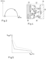
- the water content i.e. the moisture 26 of the membrane 23, is determined via a high frequency resistance (HFR) and the water content, i.e. the moisture of the cathode electrode via a low frequency resistance (LFR) (Figure 4), whereby the Figure 5 shows the correlation between the amount of water and the HFR or LFR.
- HFR high frequency resistance
- LFR low frequency resistance
- the fuel cell device 1 has a control device that is set up to carry out the above-mentioned method, wherein the fuel cell device 1 can also be used in a motor vehicle.
Description
Die Erfindung betrifft ein Verfahren zum Betreiben einer einen Brennstoffzellenstapel mit mindestens einer Brennstoffzelle aufweisenden Brennstoffzellenvorrichtung, umfassend die Schritte:
- a) Trocknen des Brennstoffzellenstapels bei einem Abstellen der Brennstoffzellenvorrichtung,
- b) Bestimmung des Membranrestwassers und des Kathodenrestwasser mittels der elektrochemischen Impedanzspektroskopie bei einem Neustart der Brennstoffzellenvorrichtung,
- c) Nutzung einer Zellspannungsüberwachungseinheit zur Identifizierung der feuchtesten Kathode in einer der Brennstoffzellen,
- d) modellbasierte Bestimmung des Wassertransports von der feuchtesten Kathode zu der Anode und damit der Anodenfeuchte in dieser Brennstoffzelle,
- e) Einstellung des elektrischen Stromes und des Brennstoffvolumenstromes in Abhängigkeit der Anodenfeuchte.
- a) drying the fuel cell stack when the fuel cell device is switched off,
- b) determination of the residual membrane water and the residual cathode water using electrochemical impedance spectroscopy when the fuel cell device is restarted,
- c) using a cell voltage monitoring unit to identify the wettest cathode in one of the fuel cells,
- d) model-based determination of the water transport from the wettest cathode to the anode and thus the anode moisture in this fuel cell,
- e) Adjustment of the electrical current and the fuel volume flow depending on the anode moisture.
Die Erfindung betrifft weiterhin eine Brennstoffzellenvorrichtung sowie ein Kraftfahrzeug mit einer Brennstoffzellenvorrichtung.The invention further relates to a fuel cell device and a motor vehicle with a fuel cell device.
Brennstoffzellenvorrichtungen werden für die chemische Umsetzung eines Brennstoffs mit Sauerstoff zu Wasser genutzt, um elektrische Energie zu erzeugen. Hierfür enthalten Brennstoffzellen als Kernkomponente die sogenannte Membran-Elektrodenanordnung, die ein Verbund aus einer protonenleitenden Membran und jeweils einer, beidseitig an der Membran angeordneten Elektrode (Anode und Kathode) ist. Zudem können Gasdiffusionslagen (GDL) beidseitig der Membran-Elektroden-Einheit an den der Membran abgewandten Seiten der Elektroden angeordnet sein. Im Betrieb der Brennstoffzellenvorrichtung mit einer Mehrzahl zu einem Brennstoffzellenstapel zusammengefasster Brennstoffzellen wird der Brennstoff, insbesondere Wasserstoff (H2) oder ein wasserstoffhaltiges Gasgemisch der Anode zugeführt, wo eine elektrochemische Oxidation von H2 zu H+ unter Abgabe von Elektronen stattfindet. Über die Membran, welche die Reaktionsräume gasdicht voneinander trennt und elektrisch isoliert, erfolgt ein (wassergebundener oder wasserfreier) Transport der Protonen H+ aus dem Anodenraum in den Kathodenraum. Die an der Anode bereitgestellten Elektronen werden über eine elektrische Leitung der Kathode zugeleitet. Der Kathode wird Sauerstoff oder ein sauerstoffhaltiges Gasgemisch zugeführt, so dass eine Reduktion von O2 zu O2- unter Aufnahme der Elektronen stattfindet. Gleichzeitig reagieren im Kathodenraum diese Sauerstoffanionen mit den über die Membran transportierten Protonen unter Bildung von Wasser. Dieses Wasser muss aus der Brennstoffzelle und dem Brennstoffzellenstapel herausgeführt werden, bis ein Feuchteniveau erreicht ist, das zum Betrieb des Brennstoffzellensystems erforderlich ist.Fuel cell devices are used to chemically convert a fuel with oxygen into water to produce electrical energy. For this purpose, fuel cells contain the so-called membrane electrode arrangement as a core component, which is a composite of a proton-conducting membrane and one on both sides of the membrane arranged electrode (anode and cathode). In addition, gas diffusion layers (GDL) can be arranged on both sides of the membrane-electrode unit on the sides of the electrodes facing away from the membrane. During operation of the fuel cell device with a plurality of fuel cells combined to form a fuel cell stack, the fuel, in particular hydrogen (H 2 ) or a hydrogen-containing gas mixture, is supplied to the anode, where an electrochemical oxidation of H 2 to H + takes place with the release of electrons. The protons H + are transported (water-bound or water-free) from the anode space into the cathode space via the membrane, which separates the reaction spaces from one another in a gas-tight manner and electrically insulates them. The electrons provided at the anode are fed to the cathode via an electrical line. Oxygen or a gas mixture containing oxygen is supplied to the cathode, so that a reduction of O 2 to O 2 - takes place with the absorption of electrons. At the same time, these oxygen anions react in the cathode space with the protons transported across the membrane to form water. This water must be removed from the fuel cell and the fuel cell stack until a moisture level is reached that is required to operate the fuel cell system.
Brennstoffzellenvorrichtungen benötigen daher ein sorgfältiges Wassermanagement, da es zum Einen erforderlich ist zu verhindern, dass zu viel Wasser sich in der Brennstoffzelle bzw. in dem Brennstoffzellenstapel befindet, was zu einer Blockade der Strömungskanäle für die Versorgung mit den Reaktanten führt. Befindet sich andererseits zu wenig Wasser in der Brennstoffzelle, ist die Protonenleitfähigkeit der Membran begrenzt, sodass auf eine ausreichende Feuchte und Wasserversorgung der Membran geachtet werden muss.Fuel cell devices therefore require careful water management since, on the one hand, it is necessary to prevent too much water from being in the fuel cell or fuel cell stack, which leads to a blockage of the flow channels for the supply of reactants. On the other hand, if there is too little water in the fuel cell, the proton conductivity of the membrane is limited, so care must be taken to ensure that the membrane has sufficient moisture and water supply.
Problematisch ist es, wenn bei einem Start der Brennstoffzellenvorrichtung Frostbedingungen vorliegen, also Bedingungen, bei denen Wasser gefriert. Dies kann dazu führen, dass die erforderlichen Strömungskanäle für die Reaktantengase und das Produktwasser durch Eis blockiert sind. Die daraus resultierende Gefahr ist eine Wasserstoffverarmung, die zu irreversiblen Schäden im Elektrodenmaterial führt.It is problematic if frost conditions exist when the fuel cell device is started, i.e. conditions in which water freezes. This can result in the necessary flow channels for the reactant gases and product water being blocked by ice. The ones from it The resulting danger is hydrogen depletion, which leads to irreversible damage to the electrode material.
Verhindert werden kann eine Wasserstoffverarmung, indem die minimale Wasserstoffstöchiometrie an jedem Ort innerhalb des Brennstoffzellenstapels bei 1 gehalten wird, wozu die Parameter des elektrischen Stromes und des Gasvolumenstromes zur Verfügung stehen. Damit diese Parameter richtig eingestellt werden können, muss der Restwassergehalt in der feuchtesten Anode bestimmt werden, bevor ein elektrischer Strom dem Brennstoffzellenstapel entnommen wird.Hydrogen depletion can be prevented by keeping the minimum hydrogen stoichiometry at 1 at every location within the fuel cell stack, for which the parameters of the electrical current and the gas volume flow are available. In order for these parameters to be set correctly, the residual water content in the wettest anode must be determined before an electrical current is drawn from the fuel cell stack.
Der Restwassergehalt auf der Anodenseite setzt sich zusammen aus dem Anodenrestwasser, dem Membranrestwasser und dem Kathodenrestwasser. Es ist bekannt, beim Abstellen der Brennstoffzellenvorrichtung, insbesondere bei drohenden Froststartbedingungen, den Brennstoffzellenstapel zu trocknen. Auf diese Weise kann der Anodenrestwassergehalt ausreichend niedrig gehalten werden. Allerdings erfolgt noch eine Diffusion des Membranrestwassers und des Kathodenrestwasser auf die Anodenseite und führt dort erneut zu Anodenrestwasser.The residual water content on the anode side is made up of the anode residual water, the membrane residual water and the cathode residual water. It is known to dry the fuel cell stack when switching off the fuel cell device, especially when frost starting conditions are imminent. In this way, the anode residual water content can be kept sufficiently low. However, the residual membrane water and the cathode residual water still diffuse to the anode side and lead to residual anode water there again.
Die
Aufgabe der vorliegenden Erfindung ist es, ein Verfahren für die Bestimmung des Anodenrestwassers insbesondere zur Vorbereitung eines Froststartes einer Brennstoffzellenvorrichtung bereitzustellen und die Möglichkeit von dessen Durchführung zu bieten.The object of the present invention is to provide a method for determining the residual anode water, in particular for preparing a frost start of a fuel cell device, and to offer the possibility of carrying it out.
Diese Aufgabe wird durch ein Verfahren mit den Merkmalen des Anspruchs 1, durch eine Brennstoffzellenvorrichtung mit den Merkmalen des Anspruchs 8 und durch ein Kraftfahrzeug mit den Merkmalen des Anspruchs 9 gelöst. Vorteilhafte Ausgestaltungen mit zweckmäßigen Weiterbildungen der Erfindung sind in den abhängigen Ansprüchen angegeben.This object is achieved by a method with the features of
Durch das erfindungsgemäße Verfahren ist erreicht, dass nicht nur ein mittlerer Restwassergehalt der gesamten Brennstoffzellenstapels bestimmt werden kann, sondern der Restwassergehalt der feuchtesten Kathode, von dem ausgehend die Diffusion auf die Anode modellbasiert, mit einem Wassertransportmodell bestimmt wird, so dass auch die Restwassermenge in der feuchtesten Anode bekannt ist und dazu die passenden Parameter für den Neustart der Brennstoffzellenvorrichtung bestimmt werden können.The method according to the invention ensures that not only an average residual water content of the entire fuel cell stack can be determined, but also the residual water content of the wettest cathode, from which the diffusion to the anode is model-based, is determined using a water transport model, so that the residual water amount in the wettest anode is known and the appropriate parameters for restarting the fuel cell device can be determined.
Die Genauigkeit des Wassertransportmodells wird verbessert, wenn die modellbasierte Bestimmung des Wassertransports die Außentemperatur bei dem Neustart und/oder die Außentemperatur bei dem Abstellen und/oder die Standzeit zwischen dem Abstellen und dem Neustart berücksichtigt.The accuracy of the water transport model is improved if the model-based determination of the water transport takes into account the outside temperature at the restart and/or the outside temperature at the shutdown and/or the idle time between the shutdown and the restart.
Wenn im Schritt e) die minimale Wasserstoffstöchiometrie für die Brennstoffzelle mit der feuchtesten Kathode auf 1 gehalten wird, dann ist sichergestellt, dass keine Wasserstoffverarmung auch bei der am stärksten gefährdeten Brennstoffzelle auftritt.If in step e) the minimum hydrogen stoichiometry for the fuel cell with the wettest cathode is kept at 1, then it is ensured that no hydrogen depletion occurs even in the most endangered fuel cell.
Zweckmäßigerweise wird über eine High Frequency Resistance (HFR) der Wassergehalt der Membran und/oder über eine Low Frequency Resistance (LFR) der Wassergehalt der Kathodenelektrode bestimmt.The water content of the membrane is expediently determined via a high frequency resistance (HFR) and/or the water content of the cathode electrode is determined via a low frequency resistance (LFR).
Die vorstehend genannten Vorteile und Wirkungen gelten sinngemäß auch für eine Brennstoffzellenvorrichtung und für ein Kraftfahrzeug mit einer Brennstoffzellenvorrichtung.The advantages and effects mentioned above also apply mutatis mutandis to a fuel cell device and to a motor vehicle with a fuel cell device.
Die vorstehend in der Beschreibung genannten Merkmale und Merkmalskombinationen sowie die nachfolgend in der Figurenbeschreibung genannten und/oder in den Figuren alleine gezeigten Merkmale und Merkmalskombinationen sind nicht nur in der jeweils angegebenen Kombination, sondern auch in anderen Kombinationen oder in Alleinstellung verwendbar, ohne den Rahmen der Erfindung zu verlassen. Es sind somit auch Ausführungen als von der Erfindung umfasst und offenbart anzusehen, die in den Figuren nicht explizit gezeigt oder erläutert sind, jedoch durch separierte Merkmalskombinationen aus den erläuterten Ausführungen hervorgehen und erzeugbar sind.The features and combinations of features mentioned above in the description as well as the features and combinations of features mentioned below in the description of the figures and/or shown in the figures alone can be used not only in the combination specified in each case, but also in other combinations or on their own, without the scope of to abandon invention. Embodiments which are not explicitly shown or explained in the figures, but which emerge from the explained embodiments through separate combinations of features and can be generated are therefore also to be regarded as being included and disclosed by the invention.
Weitere Vorteile, Merkmale und Einzelheiten der Erfindung ergeben sich aus den Ansprüchen, der nachfolgenden Beschreibung bevorzugter Ausführungsformen sowie anhand der Zeichnungen. Dabei zeigen:
- Fig. 1
- eine schematische Darstellung einer Brennstoffzellenvorrichtung,
- Fig. 2
- eine schematische Darstellung des temperaturgetriebenen Wassertransports von der Kathode zur Anode in einem Brennstoffzellenstapel, mit einer symbolisierten Temperaturskala auf der rechten Seite, hell eine niedrige Temperatur symbolisierend,
- Fig. 3
- eine schematische Darstellung eines Nyquist-Plots zur Erläuterung der High Frequency Resistance (HFR) und der Low Frequency Resistance (LFR), gezeigt für LFR bei 200 Hz (Dreieck) und HFR bei 1000 Hz (Quadrat),
- Fig. 4
- eine schematische Darstellung zur Erläuterung, welche Komponente einer Membran-Elektrodenanordnung mit HFR und LFR gemessen wird, und
- Fig. 5
- eine schematische Darstellung einer Korrelationskurve zur Impedanzabhängigkeit der Wassermasse für HRF (gepunktet) und LFR (gestrichelt).
- Fig. 1
- a schematic representation of a fuel cell device,
- Fig. 2
- a schematic representation of the temperature-driven water transport from the cathode to the anode in a fuel cell stack, with a symbolized temperature scale on the right, brightly symbolizing a low temperature,
- Fig. 3
- a schematic representation of a Nyquist plot to explain the High Frequency Resistance (HFR) and the Low Frequency Resistance (LFR), shown for LFR at 200 Hz (triangle) and HFR at 1000 Hz (square),
- Fig. 4
- a schematic representation to explain which component of a membrane electrode arrangement is measured with HFR and LFR, and
- Fig. 5
- a schematic representation of a correlation curve for the impedance dependence of the water mass for HRF (dotted) and LFR (dashed).
In der
Jede der Brennstoffzellen 2 umfasst eine Anode 21, eine Kathode 22 sowie eine die Anode 21 von der Kathode 22 trennende, protonenleitfähige Membran 23. Über einen Anodenraum kann der Anode 21 Brennstoff (zum Beispiel Wasserstoff) aus einem Brennstofftank 13 zugeführt werden. In einer Polymerelektrolytmembranbrennstoffzelle (PEM-Brennstoffzelle) werden an der Anode 21 Brennstoff oder Brennstoffmoleküle in Protonen und Elektronen aufgespaltet. Die PEM lässt die Protonen hindurch, ist aber undurchlässig für die Elektronen. An der Anode erfolgt beispielsweise die Reaktion: 2H2 → 4H+ + 4e- (Oxidation/Elektronenabgabe). Während die Protonen durch die PEM zur Kathode 22 hindurchtreten, werden die Elektronen über einen externen Stromkreis an die Kathode 22 oder an einen Energiespeicher geleitet.Each of the
Über einen Kathodenraum kann der Kathode 22 das Kathodengas (zum Beispiel Sauerstoff oder Sauerstoff enthaltende Luft) zugeführt werden, so dass kathodenseitig die folgende Reaktion stattfindet: O2 + 4H+ + 4e-→ 2H2O (Reduktion/Elektronenaufnahme).The cathode gas (for example oxygen or air containing oxygen) can be supplied to the
Da in dem Brennstoffzellenstapel 3 mehrere Brennstoffzellen 2 zusammengefasst sind, muss eine ausreichend große Menge an Kathodengas zur Verfügung gestellt werden, so dass durch einen Verdichter 18 ein großer Kathodengasmassenstrom oder Frischgasstrom bereitgestellt wird, wobei infolge der Komprimierung des Kathodengases sich dessen Temperatur stark erhöht. Die Konditionierung des Kathodengases oder des Frischluftgasstroms, also dessen Einstellung hinsichtlich der im Brennstoffzellenstapel 3 gewünschten Temperatur und Feuchte 26, erfolgt in einem dem Verdichter 18 nachgelagerten Ladeluftkühler 5 und einem diesem nachgelagerten Befeuchter 4, der eine Feuchtesättigung der Membranen 23 der Brennstoffzellen 2 zur Steigerung von deren Effizienz bewirkt, da dies den Protonentransport begünstigt.Since
Um bei einem Neustart einer Brennstoffzellenvorrichtung 1 unter Frostbedingungen Blockaden durch gefrorenes Wasser einzelner Kanäle für die Reaktantenversorgung oder von Brennstoffzellen 2 mit der damit verbundenen Gefahr einer Wasserstoffunterversorgung und daraus folgender irreversibler Schäden im Elektrodenmaterial zu vermeiden, wird ein Verfahren durchgeführt, das beginnt bei dem Abstellen der Brennstoffzellenvorrichtung 1 mit einem
- a) Trocknen des
Brennstoffzellenstapels 3, so dass der Restwassergehalt der Anoden 21 sehr niedrig eingestellt werden kann und bekannt ist.
Daran schließt sich dann bei einem Neustart der Brennstoffzellenvorrichtung 1 an die - b) Bestimmung des Membranrestwassers und des Kathodenrestwasser mittels der elektrochemischen Impedanzspektroskopie,
- c) Nutzung einer Zellspannungsüberwachungseinheit zur Identifizierung der feuchtesten Kathode 22 in
einer der Brennstoffzellen 2, - d) modellbasierte Bestimmung des Wassertransports von der feuchtesten Kathode 22 zu der
Anode 21 und damit der Anodenfeuchte indieser Brennstoffzelle 2, und - e) Einstellung des elektrischen Stromes und des Brennstoffvolumenstromes in Abhängigkeit der Anodenfeuchte.
- a) Drying the
fuel cell stack 3 so that the residual water content of theanodes 21 can be set very low and is known.
This then follows when thefuel cell device 1 is restarted - b) determination of the residual membrane water and the residual cathode water using electrochemical impedance spectroscopy,
- c) use of a cell voltage monitoring unit to identify the
wettest cathode 22 in one of thefuel cells 2, - d) model-based determination of the water transport from the
wettest cathode 22 to theanode 21 and thus the anode moisture in thisfuel cell 2, and - e) Adjustment of the electrical current and the fuel volume flow depending on the anode moisture.
Durch geeignete Wahl des von dem Brennstoffzellenstapel 2 entnommenen elektrischen Stromes und des dem Brennstoffzellenstapel 2 zugeführten Wasserstoffvolumenstromes kann so eine Wasserstoffunterversorgung auch der Brennstoffzelle 2 mit der feuchtesten Anode 21 vermieden werden, woraus sich dann ergibt, dass auch die anderen Anoden 21 in dem Brennstoffzellenstapel 3 ausreichend versorgt werden. Dazu wird im Schritt e) die minimale Wasserstoffstöchiometrie für die Brennstoffzelle 2 mit der feuchtesten Kathode auf 1 gehalten.By appropriately selecting the electrical current taken from the
Der Wassergehalt, also die Feuchte 26 der Membran 23 wird über eine High Frequency Resistance (HFR) und der Wassergehalt, also die Feuchte der Kathodenelektrode über eine Low Frequency Resistance (LFR) bestimmt (Figur 4), wobei die
Die Brennstoffzellenvorrichtung 1 verfügt über ein Steuergerät, das eingerichtet ist zur Durchführung des vorstehend genannten Verfahrens, wobei die Brennstoffzellenvorrichtung 1 auch in einem Kraftfahrzeug verwendet werden kann.The
- 11
- BrennstoffzellenvorrichtungFuel cell device
- 22
- BrennstoffzelleFuel cell
- 33
- BrennstoffzellenstapelFuel cell stack
- 44
- Befeuchterhumidifier
- 55
- Ladeluftkühlerintercooler
- 66
- BypassleitungBypass line
- 77
- Befeuchter-BypassventilHumidifier bypass valve
- 88th
- FrischluftdosierventilFresh air metering valve
- 99
- FrischluftleitungFresh air line
- 1010
- KathodenabgasleitungCathode exhaust line
- 1111
- KathodenabgasventilCathode exhaust valve
- 1212
- BrennstoffleitungFuel line
- 1313
- BrennstofftankFuel tank
- 1414
- RezirkulationsleitungRecirculation line
- 1515
- RezirkulationsgebläseRecirculation fan
- 1616
- WärmetauscherHeat exchanger
- 1717
- Randzelleedge cell
- 1818
- Verdichtercompressor
- 1919
- BrennstoffdosierventilFuel metering valve
- 2020
- WasserabscheiderWater separator
- 2121
- Anodeanode
- 2222
- Kathodecathode
- 2323
- Membranmembrane
- 2424
- EndplatteEnd plate
- 2525
- GasdiffusionslageGas diffusion layer
- 2626
- Feuchtehumidity
Claims (9)
- A method for operating a fuel cell device (1) having a fuel cell stack (3) with at least one fuel cell (2), comprising the steps:a) drying the fuel cell stack (3) at a shutdown of the fuel cell device (1),b) determining the residual membrane water and the residual cathode water by means of electrochemical impedance spectroscopy at a restart of the fuel cell device (1),c) use of a cell voltage monitoring unit to identify the wettest cathode (22) in one of the fuel cells (2),d) model-based determination of the water transport from the wettest cathode (22) to the anode (21) and thus the anode moisture in this fuel cell (2),e) adjustment of the electric current and the fuel volume flow as a function of the anode moisture.
- The method according to claim 1, characterized in that the model-based determination of the water transport takes into account the outside temperature at the restart.
- The method according to claim 1 or 2, characterized in that the model-based determination of the water transport takes into account the outside temperature at the shutdown.
- The method according to any of claims 1 to 3, characterized in that the model-based determination of the water transport takes into account the standing time between the shutdown and the restart.
- The method according to any one of claims 1 to 4, characterized in that in step e) the minimum hydrogen stoichiometry for the fuel cell (2) with the wettest cathode (22) is kept at 1.
- The method according to any on of claims 1 to 5, characterized in that the water content of the membrane (23) is determined via a high frequency resistance (HFR).
- The method according to any one of claims 1 to 6, characterized in that the water content of the cathode (22) is determined via a low frequency resistance (LFR).
- A fuel cell device (1) comprising a controller arranged to perform a method according to any one of claims 1 to 7.
- Motor vehicle with a fuel cell device (1) according to claim 8.
Applications Claiming Priority (2)
| Application Number | Priority Date | Filing Date | Title |
|---|---|---|---|
| DE102021100345.8A DE102021100345A1 (en) | 2021-01-12 | 2021-01-12 | Method for operating a fuel cell device, fuel cell device and motor vehicle with a fuel cell device |
| PCT/EP2022/050296 WO2022152632A1 (en) | 2021-01-12 | 2022-01-10 | Method for operating a fuel cell device, fuel cell device, and motor vehicle having a fuel cell device |
Publications (2)
| Publication Number | Publication Date |
|---|---|
| EP4193406A1 EP4193406A1 (en) | 2023-06-14 |
| EP4193406B1 true EP4193406B1 (en) | 2024-01-03 |
Family
ID=79316824
Family Applications (1)
| Application Number | Title | Priority Date | Filing Date |
|---|---|---|---|
| EP22700085.8A Active EP4193406B1 (en) | 2021-01-12 | 2022-01-10 | Method of operating a fuel cell system, fuel cell system, and vehicle with fuel cell system |
Country Status (5)
| Country | Link |
|---|---|
| US (1) | US20230335764A1 (en) |
| EP (1) | EP4193406B1 (en) |
| CN (1) | CN116235323A (en) |
| DE (1) | DE102021100345A1 (en) |
| WO (1) | WO2022152632A1 (en) |
Family Cites Families (4)
| Publication number | Priority date | Publication date | Assignee | Title |
|---|---|---|---|---|
| KR101416400B1 (en) | 2012-12-11 | 2014-08-07 | 현대자동차 주식회사 | Method and apparatus for diagnosing fault of fuel cell stack |
| GB2518680A (en) * | 2013-09-30 | 2015-04-01 | Intelligent Energy Ltd | Water removal in a fuel cell |
| GB2518681B (en) * | 2013-09-30 | 2021-08-25 | Intelligent Energy Ltd | Anode bleed control in a fuel cell stack |
| US20190393526A1 (en) | 2018-06-22 | 2019-12-26 | Hyster-Yale Group, Inc. | Closed loop control for fuel cell water management |
-
2021
- 2021-01-12 DE DE102021100345.8A patent/DE102021100345A1/en active Pending
-
2022
- 2022-01-10 US US18/044,760 patent/US20230335764A1/en active Pending
- 2022-01-10 WO PCT/EP2022/050296 patent/WO2022152632A1/en active Application Filing
- 2022-01-10 CN CN202280006446.8A patent/CN116235323A/en active Pending
- 2022-01-10 EP EP22700085.8A patent/EP4193406B1/en active Active
Also Published As
| Publication number | Publication date |
|---|---|
| US20230335764A1 (en) | 2023-10-19 |
| WO2022152632A1 (en) | 2022-07-21 |
| DE102021100345A1 (en) | 2022-07-14 |
| EP4193406A1 (en) | 2023-06-14 |
| CN116235323A (en) | 2023-06-06 |
Similar Documents
| Publication | Publication Date | Title |
|---|---|---|
| DE102010005294B4 (en) | A fuel cell system and method for purging water from a fuel cell stack at system shutdown | |
| DE102009023882B4 (en) | Fuel cell system and method for reliably starting the same | |
| DE102011014969B4 (en) | A method of operating a fuel cell system in a standby mode | |
| DE102015207600A1 (en) | Method for controlling an operating point change of a fuel cell stack and fuel cell system | |
| EP4082059A1 (en) | Cell unit | |
| DE102020113105A1 (en) | Method of turning off a fuel cell device | |
| EP4193406B1 (en) | Method of operating a fuel cell system, fuel cell system, and vehicle with fuel cell system | |
| DE102020100599A1 (en) | Method for a freeze start of a fuel cell system, fuel cell system and motor vehicle with such a system | |
| DE102021207855A1 (en) | Method of monitoring an electrochemical cell unit | |
| DE102020115662A1 (en) | Method for determining the thermal aging of a fuel cell stack and fuel cell system | |
| WO2022053191A1 (en) | Method for distinguishing the cause of voltage losses in a fuel cell device, fuel cell device and motor vehicle having such a device | |
| DE102020128127A1 (en) | Method for operating a fuel cell system and fuel cell system | |
| DE102009023880A1 (en) | Modified commissioning strategy to improve commissioning reliability after a longer shutdown time | |
| DE102019128422A1 (en) | Method for restarting a fuel cell device after a previous shutdown, fuel cell device and motor vehicle | |
| DE102020114746B4 (en) | Method for shutting down a fuel cell device and fuel cell device and motor vehicle | |
| DE102022101359A1 (en) | Method for operating a fuel cell device, fuel cell device and motor vehicle with a fuel cell device | |
| DE102020128273A1 (en) | Method for a frost start of a fuel cell device, fuel cell device and motor vehicle with a fuel cell device | |
| DE102020123937A1 (en) | Method for operating a fuel cell device, fuel cell device and fuel cell vehicle with such | |
| DE102019132960A1 (en) | Method for a freeze start of a fuel cell device, fuel cell device and motor vehicle with a fuel cell device | |
| DE102020100598A1 (en) | Method for operating a fuel cell device, fuel cell device and motor vehicle | |
| DE102020115375A1 (en) | Method for parking a fuel cell vehicle and fuel cell vehicle | |
| DE102020125932A1 (en) | Fuel cell system and operating method for reduced fuel partial pressure in the anode circuit and vehicle with such a fuel cell system | |
| DE102020113325A1 (en) | Method of operating a fuel cell device | |
| DE102019132950A1 (en) | Method for operating a fuel cell device, fuel cell device and motor vehicle with such | |
| DE102020123933A1 (en) | Method for operating a fuel cell device, fuel cell device and fuel cell vehicle |
Legal Events
| Date | Code | Title | Description |
|---|---|---|---|
| STAA | Information on the status of an ep patent application or granted ep patent |
Free format text: STATUS: UNKNOWN |
|
| STAA | Information on the status of an ep patent application or granted ep patent |
Free format text: STATUS: THE INTERNATIONAL PUBLICATION HAS BEEN MADE |
|
| PUAI | Public reference made under article 153(3) epc to a published international application that has entered the european phase |
Free format text: ORIGINAL CODE: 0009012 |
|
| STAA | Information on the status of an ep patent application or granted ep patent |
Free format text: STATUS: REQUEST FOR EXAMINATION WAS MADE |
|
| 17P | Request for examination filed |
Effective date: 20230309 |
|
| AK | Designated contracting states |
Kind code of ref document: A1 Designated state(s): AL AT BE BG CH CY CZ DE DK EE ES FI FR GB GR HR HU IE IS IT LI LT LU LV MC MK MT NL NO PL PT RO RS SE SI SK SM TR |
|
| GRAP | Despatch of communication of intention to grant a patent |
Free format text: ORIGINAL CODE: EPIDOSNIGR1 |
|
| STAA | Information on the status of an ep patent application or granted ep patent |
Free format text: STATUS: GRANT OF PATENT IS INTENDED |
|
| INTG | Intention to grant announced |
Effective date: 20231017 |
|
| GRAS | Grant fee paid |
Free format text: ORIGINAL CODE: EPIDOSNIGR3 |
|
| GRAA | (expected) grant |
Free format text: ORIGINAL CODE: 0009210 |
|
| STAA | Information on the status of an ep patent application or granted ep patent |
Free format text: STATUS: THE PATENT HAS BEEN GRANTED |
|
| AK | Designated contracting states |
Kind code of ref document: B1 Designated state(s): AL AT BE BG CH CY CZ DE DK EE ES FI FR GB GR HR HU IE IS IT LI LT LU LV MC MK MT NL NO PL PT RO RS SE SI SK SM TR |
|
| DAV | Request for validation of the european patent (deleted) | ||
| DAX | Request for extension of the european patent (deleted) | ||
| REG | Reference to a national code |
Ref country code: GB Ref legal event code: FG4D Free format text: NOT ENGLISH |
|
| REG | Reference to a national code |
Ref country code: CH Ref legal event code: EP |
|
| REG | Reference to a national code |
Ref country code: DE Ref legal event code: R096 Ref document number: 502022000379 Country of ref document: DE |
|
| REG | Reference to a national code |
Ref country code: IE Ref legal event code: FG4D Free format text: LANGUAGE OF EP DOCUMENT: GERMAN |
|
| REG | Reference to a national code |
Ref country code: LT Ref legal event code: MG9D |