EP4193232B1 - Fahrzeugsteuerung - Google Patents
Fahrzeugsteuerung Download PDFInfo
- Publication number
- EP4193232B1 EP4193232B1 EP21749268.5A EP21749268A EP4193232B1 EP 4193232 B1 EP4193232 B1 EP 4193232B1 EP 21749268 A EP21749268 A EP 21749268A EP 4193232 B1 EP4193232 B1 EP 4193232B1
- Authority
- EP
- European Patent Office
- Prior art keywords
- route
- unmanned aerial
- aerial vehicle
- vehicle
- control signal
- Prior art date
- Legal status (The legal status is an assumption and is not a legal conclusion. Google has not performed a legal analysis and makes no representation as to the accuracy of the status listed.)
- Active
Links
Images

Classifications
-
- G—PHYSICS
- G05—CONTROLLING; REGULATING
- G05D—SYSTEMS FOR CONTROLLING OR REGULATING NON-ELECTRIC VARIABLES
- G05D1/00—Control of position, course, altitude or attitude of land, water, air or space vehicles, e.g. using automatic pilots
- G05D1/0088—Control of position, course, altitude or attitude of land, water, air or space vehicles, e.g. using automatic pilots characterized by the autonomous decision making process, e.g. artificial intelligence, predefined behaviours
-
- B—PERFORMING OPERATIONS; TRANSPORTING
- B64—AIRCRAFT; AVIATION; COSMONAUTICS
- B64U—UNMANNED AERIAL VEHICLES [UAV]; EQUIPMENT THEREFOR
- B64U10/00—Type of UAV
- B64U10/10—Rotorcrafts
- B64U10/13—Flying platforms
-
- G—PHYSICS
- G05—CONTROLLING; REGULATING
- G05D—SYSTEMS FOR CONTROLLING OR REGULATING NON-ELECTRIC VARIABLES
- G05D1/00—Control of position, course, altitude or attitude of land, water, air or space vehicles, e.g. using automatic pilots
- G05D1/0011—Control of position, course, altitude or attitude of land, water, air or space vehicles, e.g. using automatic pilots associated with a remote control arrangement
- G05D1/0022—Control of position, course, altitude or attitude of land, water, air or space vehicles, e.g. using automatic pilots associated with a remote control arrangement characterised by the communication link
-
- G—PHYSICS
- G05—CONTROLLING; REGULATING
- G05D—SYSTEMS FOR CONTROLLING OR REGULATING NON-ELECTRIC VARIABLES
- G05D1/00—Control of position, course, altitude or attitude of land, water, air or space vehicles, e.g. using automatic pilots
- G05D1/0055—Control of position, course, altitude or attitude of land, water, air or space vehicles, e.g. using automatic pilots with safety arrangements
-
- G—PHYSICS
- G05—CONTROLLING; REGULATING
- G05D—SYSTEMS FOR CONTROLLING OR REGULATING NON-ELECTRIC VARIABLES
- G05D1/00—Control of position, course, altitude or attitude of land, water, air or space vehicles, e.g. using automatic pilots
- G05D1/02—Control of position or course in two dimensions
- G05D1/0202—Control of position or course in two dimensions specially adapted to aircraft
-
- G—PHYSICS
- G05—CONTROLLING; REGULATING
- G05D—SYSTEMS FOR CONTROLLING OR REGULATING NON-ELECTRIC VARIABLES
- G05D1/00—Control of position, course, altitude or attitude of land, water, air or space vehicles, e.g. using automatic pilots
- G05D1/10—Simultaneous control of position or course in three dimensions
- G05D1/101—Simultaneous control of position or course in three dimensions specially adapted for aircraft
-
- G—PHYSICS
- G08—SIGNALLING
- G08G—TRAFFIC CONTROL SYSTEMS
- G08G5/00—Traffic control systems for aircraft
- G08G5/20—Arrangements for acquiring, generating, sharing or displaying traffic information
-
- G—PHYSICS
- G08—SIGNALLING
- G08G—TRAFFIC CONTROL SYSTEMS
- G08G5/00—Traffic control systems for aircraft
- G08G5/20—Arrangements for acquiring, generating, sharing or displaying traffic information
- G08G5/22—Arrangements for acquiring, generating, sharing or displaying traffic information located on the ground
-
- G—PHYSICS
- G08—SIGNALLING
- G08G—TRAFFIC CONTROL SYSTEMS
- G08G5/00—Traffic control systems for aircraft
- G08G5/20—Arrangements for acquiring, generating, sharing or displaying traffic information
- G08G5/26—Transmission of traffic-related information between aircraft and ground stations
-
- G—PHYSICS
- G08—SIGNALLING
- G08G—TRAFFIC CONTROL SYSTEMS
- G08G5/00—Traffic control systems for aircraft
- G08G5/30—Flight plan management
- G08G5/34—Flight plan management for flight plan modification
-
- G—PHYSICS
- G08—SIGNALLING
- G08G—TRAFFIC CONTROL SYSTEMS
- G08G5/00—Traffic control systems for aircraft
- G08G5/50—Navigation or guidance aids
- G08G5/53—Navigation or guidance aids for cruising
-
- G—PHYSICS
- G08—SIGNALLING
- G08G—TRAFFIC CONTROL SYSTEMS
- G08G5/00—Traffic control systems for aircraft
- G08G5/50—Navigation or guidance aids
- G08G5/55—Navigation or guidance aids for a single aircraft
-
- G—PHYSICS
- G08—SIGNALLING
- G08G—TRAFFIC CONTROL SYSTEMS
- G08G5/00—Traffic control systems for aircraft
- G08G5/50—Navigation or guidance aids
- G08G5/56—Navigation or guidance aids for two or more aircraft
-
- B—PERFORMING OPERATIONS; TRANSPORTING
- B64—AIRCRAFT; AVIATION; COSMONAUTICS
- B64U—UNMANNED AERIAL VEHICLES [UAV]; EQUIPMENT THEREFOR
- B64U2201/00—UAVs characterised by their flight controls
- B64U2201/20—Remote controls
-
- G—PHYSICS
- G05—CONTROLLING; REGULATING
- G05D—SYSTEMS FOR CONTROLLING OR REGULATING NON-ELECTRIC VARIABLES
- G05D1/00—Control of position, course, altitude or attitude of land, water, air or space vehicles, e.g. using automatic pilots
- G05D1/10—Simultaneous control of position or course in three dimensions
- G05D1/101—Simultaneous control of position or course in three dimensions specially adapted for aircraft
- G05D1/104—Simultaneous control of position or course in three dimensions specially adapted for aircraft involving a plurality of aircrafts, e.g. formation flying
-
- G—PHYSICS
- G08—SIGNALLING
- G08G—TRAFFIC CONTROL SYSTEMS
- G08G5/00—Traffic control systems for aircraft
- G08G5/50—Navigation or guidance aids
- G08G5/57—Navigation or guidance aids for unmanned aircraft
-
- G—PHYSICS
- G08—SIGNALLING
- G08G—TRAFFIC CONTROL SYSTEMS
- G08G5/00—Traffic control systems for aircraft
- G08G5/80—Anti-collision systems
Definitions
- the at least one unmanned vehicle may comprise an unmanned aerial vehicle.
- the system may comprise a server configured to transmit each of a plurality of routes to the respective apparatus coupled to the unmanned vehicle that will follow the route.
- the server may comprise a route deconfliction algorithm for performing route deconfliction on a plurality of routes and generating the route for the respective unmanned vehicle to follow.
- a method of controlling an unmanned vehicle comprising:
- the method may comprise mechanically coupling a vehicle controller to the vehicle.
- the method may comprise receiving the route for the vehicle to follow wirelessly from a server.
- the method may comprise transmitting navigation data to the server and using the navigation data to plan the route for the vehicle to follow.
- the method may comprise determining the route for the vehicle to follow by performing route deconfliction on a plurality of routes and storing the determined route.
- the method may comprise retrieving object data and using the object data to perform route deconfliction, such that the unmanned vehicle does not collide with objects associated with the object data.
- Retrieving object data may include searching a database.
- Object data may include architectural and/or terrain data, such as heights and locations of buildings and mountains.
- Object data may include air traffic data, such as the flight paths of aircraft, or ADS-B data.
- the method may comprise:
- the method may comprise receiving the second vehicle control signal and controlling the unmanned vehicle to perform the manoeuvre instructed by the second vehicle control signal.
- embodiments herein relate to a vehicle controller that can be coupled to a "dumb" unmanned vehicle, after manufacture, in order to provide the unmanned vehicle with autonomy.
- the vehicle controller receives a route (i.e. travel plan) from a server for the unmanned vehicle to follow.
- the server is provided with software that prevents collisions with other unmanned vehicles.
- the unmanned vehicle requires no modification in order to accommodate the vehicle controller, and therefore the vehicle controller is compatible with any unmanned vehicle ordinarily controlled from a control station or handheld device. Therefore, several vehicle controllers may be centrally programmed for the control of several associated unmanned vehicles, negating the need for manual user control of each unmanned vehicle.
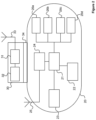
- Unmanned aerial vehicles 20a, 20b having respective individual vehicle controllers 30a, 30b (generally 30) coupled thereto are illustrated in Figure 1 . While two UAVs 20 are illustrated, this is not intended to be limiting. There may be only one UAV 20 in the system, or a plurality of UAVs 20 in the system.
- the unmanned aerial vehicle 20 is in the form of a multicopter (e.g. a quadcopter), which is a typical form-factor for COTS UAVs. While the embodiments that follow will refer to flight paths, flight planning and aircraft, it would be understood this is in relation to specific embodiments and not intended to limit the concept of upscaling autonomy.
- the unmanned vehicle may be an unmanned or optionally-manned ground vehicle, space vehicle or naval vessel. Throughout, "unmanned" will be assumed to have a broad definition encompassing optionally-manned vehicles not being operated by a human.
- the unmanned aerial vehicle(s) 20 in normal operation the unmanned aerial vehicle(s) 20 is/are controlled manually using an associated handheld remote controller 10a, 10b (generally 10).
- the handheld remote controller 10a, 10b is unique to the respective UAV 20a, 20b.
- the first handheld remote controller 10a could not control the second UAV 20b to which it is not linked. This is because the UAVs 20a, 20b operate on different channels or frequencies to each other.
- the unmanned aerial vehicle(s) 20 in normal operation the unmanned aerial vehicle(s) 20 is/are controlled manually by or from a control station.
- the unmanned aerial vehicle 20 is a commercial-off-the-shelf "drone", and as such is relatively inexpensive and has a limited degree of autonomy, if any.
- the unmanned aerial vehicle 20 receives a wireless control signal from the remote controller 10, containing instructions to change the heading, orientation, velocity and/or altitude of the unmanned aerial vehicle 20.
- the remote controller 10 may be a mobile phone, handheld bespoke transmitter, joystick, trackball, desktop computer, or other wireless control device. These instructions are interpreted by a controller on-board the UAV 20 such that it generates corresponding control signals for the unmanned aerial vehicle's flight control surfaces in order to effect the desired manoeuvre.
- a vehicle controller 30 is coupled to the UAV 20.
- the vehicle controller 30 is an independent unit attached to the outside of the UAV 20.
- the vehicle controller 30 may be coupled to the UAV 20 by any suitable means, such as straps, an adhesive substance, a magnet, hook-and-loop material, a clasp, a bracket, or an elastic band.
- the vehicle controller 30 may alternatively be heat-bonded or chemically bonded to the UAV 20, although it would be preferred for the vehicle controller 30 to be detachable such that the UAV 20 can return to its original control regime.
- the vehicle controller 30 is arranged to generate and transmit its own control signals having the same characteristics as those transmitted by the linked remote controller 10 in order to control the UAV 20 instead of that remote controller 10.
- the characteristics may include frequency, channel, power and/or amplitude, for example, such that the UAV 20 recognises the vehicle controller 30 to be the remote controller 10.
- the vehicle controller 30 may be manually programmed to transmit using the appropriate characteristics, or may detect the appropriate characteristics by measuring intercepted signals transmitted by the remote controller 10.
- a server 40 is in wireless communication with the plurality of vehicle controllers 30.
- the server 40 may belong to an entity such as a logistics company, national air traffic service or military organisation, having a plurality of UAVs 20 associated with it.
- the UAVs 20 may be for delivering packages, for example.
- the UAVs 20 may be communication nodes in a military tactical network.
- the server 40 may receive a start point (e.g. the current position of the UAV 20) for a route and a desired end point (e.g. where a package needs to be delivered).
- the server 40 is arranged to plan a route between the two points.
- the route is planned such that the UAV 20 does not collide with any other UAVs, terrain or objects.
- the route may be planned such that the UAV 20 moves from the start point to the end point "as the crow flies" (i.e. with little deviation from a straight path).
- the vehicle controllers 30 are arranged to transmit navigation data (e.g. their position, velocity and/or heading) to the server 40.
- the server 40 is arranged to use this navigation data to perform route deconfliction.
- Route deconfliction may first involve extrapolating a route of each UAV 20 using the respective navigation data. For example, if a UAV 20 is shown to be at a first location at a first time, and its speed and direction of travel are transmitted to the server 40, the server 40 can calculate its position at a second time. Deconfliction may then involve generating new routes for the UAVs 20 that prevent their collision if the original routes are shown to intersect. Alternatively, where original routes are shown to intersect and where the server 40 is provided with a terminal having a user interface, a user may manually generate a new route for each UAV 20 to remove the conflict(s).
- the server 40 may also be aware of the locations of other objects (or, in other words, entities), such as manned aircraft, aerostats, storm fronts or terrain features.
- This data may be received through the internet, via a databus or may be pre-stored.
- the server 40 may receive map data, such as topography data or architectural data.
- the map data may indicate the elevation or maximum vertical extent of terrain features (e.g. mountains) or buildings, along with their locations.
- the map data may be received from a remote server via a communications link, or may be downloaded to a memory on the server 40.
- the server 40 may also have access to national air traffic data systems, or have an Automatic Dependent Surveillance-Broadcast (ADS-B) input, so that it knows the location and trajectory (or flight paths) of other aircraft.
- the routes may be generated so as to avoid collision between the UAVs 20 and these objects (in addition to avoiding collision between the UAVs 20 themselves).
- a user may programme the server 40 with the desired routes for each UAV 20.
- Each route is then transmitted back to the vehicle controller 30 coupled to the UAV 20 associated with the respective route. As illustrated, the route is transmitted to the vehicle controller 30 over-the-air.
- the vehicle controllers 30 may be coupled to the server 40 via a network, for example a wide area network (WAN) or local area network (LAN).
- WAN wide area network
- LAN local area network
- the route is a path through a three-dimensional region of airspace, and therefore may indicate a sequential set of coordinates and altitudes.
- the route is a plan for moving a UAV 20 from a start position to a final position.
- the route may further include the velocity at which the UAV 20 should fly between coordinates, an expected time of arrival at particular coordinates (from which velocity can be calculated), and/or the UAV's (or UAV's camera) orientation at particular coordinates.
- the vehicle controller 30 or server 40 is pre-programmed with a route for the UAV 20 follow. Deviations from this stored route may be transmitted to the server 40 so that adjustments to the UAV 20 can be made to bring it back onto the planned route.
- the vehicle controller 30 may be configured to determine corrections to bring the UAV 20 back onto the planned route.
- the server 40 may be used to plan and store routes, without performing any route deconfliction.
- a user may generate a route using an application on their handheld mobile device (e.g. mobile phone), and transmit that route to the vehicle controller 30 via a wireless communication means such as WiFi or Bluetooth.
- This route may also be transmitted to and/or stored on the server 40 such that route deconfliction can be performed as explained above (in lieu of or in addition to receiving navigation data at the server 40).
- the vehicle controller 30 may comprise a user interface, such as a touchscreen, for receiving a route from a user.
- the vehicle controller 30 may comprise a wired interface for receiving a route from a computer or the server 40 as illustrated in Figure 1 .
- the vehicle controller 30 may instead comprise an interface for receiving a route from a USB stick or external hard drive.
- the vehicle controller 30 is reprogrammable to receive alternative routes and/or control different UAVs 20.
- the route may be programmed at the time of manufacture of the vehicle controller 30.
- the vehicle controller 30 may comprise a route deconfliction algorithm.
- the vehicle controller 30 may receive one or a plurality of routes.
- the vehicle controller 30 may also be aware of the locations of other objects to be avoided, such as manned aircraft etc., as explained with reference to the server 40 above.
- Each route, and/or object data, may be received by any of the mechanisms previously described.
- the vehicle controller 30 may then calculate a route for the UAV 20 to follow which does not result in collision with another UAV 20 following one of the received routes, or one of the objects.
- the route deconfliction algorithm (such as that used by the server 40 or vehicle controller 30) defines a three-dimensional region of airspace around part of the or each received route.
- the three-dimensional region of airspace is time-dependent, in that it moves along the route to align with the expected position of the associated aircraft at that point in time.
- the deconfliction algorithm may then warn a user (for example, with a displayed message) if their intended route intersects one of the other three-dimensional regions so they can replan, or calculates a route to avoid such an event.
- the vehicle controller 30 comprises at least one sensor for determining live situational awareness data.
- This situational awareness data may be used to adapt or determine a route for the UAV 20.
- Live situational awareness data may indicated the presence of another aircraft or object moving into the path of the UAV 20, for example.
- the sensor may be an optical camera, radar, sonar, hyperspectral imaging device, infrared camera, etc.
- the sensor may comprise a laser range finder for determining the distance to a detected object.
- the sensor may comprise image recognition software to identify clouds and other object types.
- the situational awareness data may be transmitted to the server 40 so that the server 40 can modify the determined route.
- Modifying a route may involve instructing the UAV 20 to accelerate, such that the object passes behind the UAV 20; slow down; or change direction.
- the server 40 or a processor on-board the vehicle controller 30, may calculate the speed and direction of travel of the object and the point of likely intersection with the UAV 20 if it remains on the route presently being followed. This may be achieved by monitoring how far the object (or aircraft) travels in a known amount of time.
- the laser range finder or radar may be used for this purpose.
- the vehicle controller 30 itself may be configured to modify the stored route to control the UAV 20 to avoid the object (or other aircraft).
- FIG. 2 An embodiment of a vehicle controller 30 coupled to a UAV 20 is illustrated in more detail in Figure 2 .
- the vehicle controller 30 is for storing a predetermined route (i.e. a flight plan) and generating control signals (i.e. control inputs) for controlling the UAV 20 to follow the route.
- the route is stored in a memory 32.
- the memory 32 may be a non-volatile memory such as read only memory (ROM), a hard disk drive (HDD) or a solid state drive (SSD).
- the memory 32 may include random access memory (RAM).
- RAM is used by a controller 31 of the vehicle controller 30 for the temporary storage of data.
- the memory 32 in alternative embodiments, may comprise a route deconfliction algorithm used by the controller 31 in planning a route.
- a route is initially programmed by a user using their mobile device (e.g. mobile phone).
- the mobile device uses a web app running on a server 40 to receive the route.
- This initial route is stored on the server 40, which also stores a plurality of other routes each associated with other UAVs 20. These other routes may be received from the same mobile device (i.e. the same user) or a plurality of mobile devices.
- the server 40 performs route deconfliction on the stored routes to generate a deconflicted route for the UAV 20 to follow.
- the deconflicted route may be the same as the initial route, if there were no conflicts with other UAVs or objects.
- This deconflicted route is transmitted to the vehicle controller 30 and stored in the memory 32.
- the memory 32 may contain a unique identifier, such as a MAC address, serial number or email address, to set the vehicle controller 30 apart from other vehicle controllers with which the server 40 is in communication.
- the vehicle controller 30 may determine a route for the UAV 20 to follow based on situational awareness data received from sensors onboard the vehicle controller 30. Therefore, the vehicle controller 30 may include sensors, such as a radar or optical camera, for detecting aerial objects to avoid such as other aircraft or weather patterns. Alternatively, the vehicle controller 30 and UAV 20 may be provided with an electrical interface to allow the vehicle controller 30 to access sensors onboard the UAV 20. This sensor data may be used as part of the route planning process (e.g. by first being transmitted to the server 40), or may be used directly by the vehicle controller 30 to deviate from a route where unexpected obstacles arise.
- the vehicle controller 30 comprises a navigation system, such as an inertial navigation system including a gyroscope and/or compass.
- the navigation system may alternatively or additionally include a satellite navigation system such as GPS or GLONASS.
- the navigation system generates navigation data such as the location, heading and velocity of the UAV 20.
- the navigation data is transmitted to the server 40.
- a route can then be planned for the UAV 20 using the UAV's current conditions (i.e. location, heading and velocity).
- the route is transmitted to the associated vehicle controller 30 for storage.
- the server 40 may predict the present position velocity and heading of the UAV 20 based on time of flight and initial conditions.
- the vehicle controller 30 may comprise a data interface.
- the data interface may be a wired interface such as a serial port, USB interface, or Ethernet interface.
- the data interface may be a wireless interface such as a Bluetooth, LTE, 5g, 6g, or WiFi module.
- the data interface is for receiving the or a plurality of routes from the server 40.
- the vehicle controller 30 may receive the route from a user's mobile device or through a direct input means such as a touchscreen.
- the controller 31 is coupled to an antenna 33.
- the antenna 33 receives (intercepts) control signals transmitted by the handheld remote controller 10, intended for the UAV 20.
- the controller 31 (or, in some embodiments, a separate signal processor) processes the received control signals to determine the characteristics of signals usually used to control the UAV 20.
- the controller 31 may comprise a transducer.
- the controller 31 may comprise a spectrum analyser for determining the frequency of received signals.
- the controller 31 is not tuned to a specific frequency, and is able to process signals on a range of frequencies in order to determine their frequency (and, in some cases, other characteristics, such as transmission channel). This allows the controller 31 to generate its own control signals for the UAV 20, having the same characteristics as the received signals. Therefore, the vehicle controller 30 can be used to control any UAV 20, rather than being limited to one UAV only during manufacture as in the prior art. In other words, a vehicle controller 30 may be used to retrofit a UAV 20.
- the controller 31 may take any suitable form. For instance, it may be a microcontroller, plural microcontrollers, a processor, or plural processors.
- the controller 31 is arranged to generate control signals for controlling the UAV 20 to manoeuvre to follow the route stored in the memory 32. For example, thirty seconds into the flight, the route may indicate the UAV 20 needs to head on a bearing of 130 degrees north. Knowing the original heading of the UAV 20, the vehicle controller 30 may therefore generate a control signal, thirty seconds into the flight, indicating the UAV 20 to turn left until it is on the indicated heading. Instead of being based on timings, the control signals may be generated according to the position of the UAV 20 relative to the route. A set of control signals may be generated by the controller 31, whereby each control signal defines a manoeuvre, which, if all executed by the UAV 20, causes the UAV 20 to follow the stored route. The control signals are transmitted to the UAV 20 through the antenna 33.
- the vehicle controller 30 includes a mechanical interface 34 for coupling the vehicle controller 30 to the UAV 20.
- the mechanical interface 34 in preferred embodiments, requires no modification of the UAV 20 itself to secure the vehicle controller 30.
- the mechanical interface 34 may include any suitable securing means, such as an adhesive layer, magnet or a strap that wraps around the body of the UAV 20.
- the mechanical interface 34 may also include a net or basket, or the like, for suspending the vehicle controller 30 below the UAV 20.
- the vehicle controller 30 is attached to an outside surface of the UAV 20 by the mechanical interface 34. The surface may, for example, by an upper (dorsal) part of the main body of the UAV 20, as illustrated in Figure 1 .
- the vehicle controller 30 may be coupled to a side surface or the lower (ventral) part of the main body of the UAV 20.
- “attached” and “coupled” may not mean literally affixed, rather, the terms are intended to mean “held in place in relatively close proximity to, or touching, the surface", such that the vehicle controller 30 does not fall from the UAV 20 in flight and signals can be transmitted to the UAV 20.
- the UAV 20 is a commercial-off-the-shelf (COTS) quadcopter aircraft weighing about 15kg and having diameter of less than 1 metre.
- COTS commercial-off-the-shelf
- the vehicle controller 30 may be coupled to an unmanned vehicle of any size or configuration to provide that vehicle with a degree of autonomy.
- the present invention requires no modification of the UAV 20, and therefore the UAV 20 may be any UAV typical of the prior art.
- the vehicle to be controlled may take the form of an unmanned ground vehicle or naval vessel (including underwater vessels).
- the UAV 20 may be solar-electric powered (where the power source is not shown in the Figure). However, in other embodiments, the primary power source of the UAV 20 may be hybrid, battery only, hydrogen, or hydrocarbon based.
- the UAV 20 comprises a controller 21.
- the controller 21 may take any suitable form. For instance, it may be a microcontroller, plural microcontrollers, a processor, or plural processors.
- the controller 21 is arranged to receive control signals decoded by a radio 24 (i.e. a signal processor).
- the radio 24 receives the control signals wirelessly through an antenna 25 from the remote controller 10 unless the remote controller 10 is out of range.
- the control signals contain instructions, which, when executed by the controller 21, cause the UAV 20 to move according to a user input.
- the functionality of the radio 24 is performed by the controller 21.
- the radio 24 comprises a transducer tuned to a specific channel and frequency, and is therefore associated with a specific remote controller 10 during manufacture.
- the UAV 20 depicted in the Figures is a quadcopter-type unmanned aerial vehicle, with four propulsion units 26a-d that can be adjusted to control pitch/attitude, velocity, orientation, heading and lift of the UAV 20.
- the UAV 20 may take a different form, such as that of a traditional aeroplane, helicopter, airship, vertical take-off and/or landing aircraft, or balloon. Therefore, in other embodiments, the vehicle may comprise less than or more than four propulsion units 26a-d.
- the vehicle comprises flight control surfaces such as rotors, elevators, ailerons, flaps, and propellers.
- the controller 21 may execute the instructions in the control signal by independently controlling each of the propulsion units 26a-d to increase or decrease the velocity of the UAV 20.
- the controller 21 is arranged to generate control signals to control the propulsion units 26a-d (or other flight control surfaces) to change the heading and/or orientation and/or altitude and/or attitude and/or velocity of the UAV 20 such that it follows the route stored in the memory 32 of the vehicle controller 30.
Landscapes
- Engineering & Computer Science (AREA)
- Aviation & Aerospace Engineering (AREA)
- Physics & Mathematics (AREA)
- General Physics & Mathematics (AREA)
- Remote Sensing (AREA)
- Radar, Positioning & Navigation (AREA)
- Automation & Control Theory (AREA)
- Mechanical Engineering (AREA)
- Business, Economics & Management (AREA)
- Health & Medical Sciences (AREA)
- Artificial Intelligence (AREA)
- Evolutionary Computation (AREA)
- Game Theory and Decision Science (AREA)
- Medical Informatics (AREA)
- Traffic Control Systems (AREA)
- Navigation (AREA)
- Control Of Position, Course, Altitude, Or Attitude Of Moving Bodies (AREA)
Claims (14)
- Vorrichtung (30) zum Steuern eines unbemannten Luftfahrzeugs (20), die Vorrichtung umfassend:einen Empfänger (33) zum Abfangen eines ersten Steuersignals, das von einer für das unbemannte Luftfahrzeug vorgesehenen Fernsteuerung (10) gesendet wird;einen Speicher (32) zum Speichern einer Route, der das unbemannte Luftfahrzeug folgen soll;einen Prozessor (31), der konfiguriert ist zum:Bestimmen von Eigenschaften des ersten Steuersignals; und,Erzeugen eines zweiten Steuersignals, wobei das zweite Steuersignal eine Anweisung für das unbemannte Luftfahrzeug umfasst, ein Manöver durchzuführen, um der Route zu folgen; und,einen Sender, der konfiguriert ist, um das zweite Steuersignal, das eingerichtet ist, um die bestimmten Eigenschaften aufzuweisen, an das unbemannte Luftfahrzeug zu senden,wobei der Prozessor (31) ferner eingerichtet ist, um eine Vielzahl von Routen zu empfangen, die Route, der das unbemannte Luftfahrzeug (20) folgen soll, durch Durchführen einer Routenkonfliktbeseitigung auf der Vielzahl von Routen zu bestimmen, und die bestimmte Route in dem Speicher (32) zu speichern.
- Vorrichtung (30) nach Anspruch 1, wobei die Eigenschaften mindestens eines von einem Kanal und einer Frequenz einschließen, auf dem/der das erste Steuersignal von der Fernsteuerung (10) gesendet wird.
- Vorrichtung (30) nach Anspruch 1 oder 2, umfassend ein Navigationssystem zum Erzeugen von Navigationsdaten,
wobei der Sender eingerichtet ist, um die Navigationsdaten an einen Server (40) zu senden, und der Empfänger (33) eingerichtet ist, um die Route von dem Server zu empfangen. - Vorrichtung (30) nach einem der vorstehenden Ansprüche, wobei der Prozessor (31) eingerichtet ist, um die Route, der das unbemannte Luftfahrzeug (20) folgen soll, zu bestimmen und die Route in dem Speicher (32) zu speichern.
- Vorrichtung (30) nach Anspruch 4, umfassend mindestens einen Sensor, wobei das Bestimmen der Route, der das unbemannte Luftfahrzeug (20) folgen soll, ein Modifizieren einer gespeicherten Route basierend auf Daten umfasst, die durch den mindestens einen Sensor erzeugt werden.
- Vorrichtung (30) nach einem der vorstehenden Ansprüche, umfassend ein Kopplungsmittel (34) zum Koppeln der Vorrichtung an eine Außenoberfläche des unbemannten Luftfahrzeugs (20).
- Vorrichtung (30) nach Anspruch 6, wobei das Kopplungsmittel (34) eine Klebeschicht umfasst.
- System zum Steuern eines unbemannten Luftfahrzeugs, das System umfassend:mindestens eine Vorrichtung (30) nach einem der vorstehenden Ansprüche; undmindestens ein unbemanntes Luftfahrzeug (20) zum Empfangen eines Steuersignals von der Vorrichtung und zum Ausführen eines durch das zweite Steuersignal angewiesenen Manövers, wobei mindestens die eine Vorrichtung mit dem jeweiligen mindestens einen unbemannten Luftfahrzeug gekoppelt ist.
- System nach Anspruch 8, umfassend einem Server (40), der konfiguriert ist, um jede einer Vielzahl von Routen an die jeweilige Vorrichtung (30) zu senden, die mit dem unbemannten Luftfahrzeug (20) gekoppelt ist, das der Route folgen wird.
- System nach Anspruch 9, wobei der Server (40) einen Routenkonfliktbeseitigungsalgorithmus zum Durchführen der Routenkonfliktbeseitigung auf einer Vielzahl von Routen und zum Erzeugen der Route, der das jeweilige unbemannte Luftfahrzeug (20) folgen soll, umfasst.
- System nach Anspruch 9 oder 10, wobei die mindestens eine Vorrichtung (30) eingerichtet ist, um Navigationsdaten in Bezug auf das jeweilige unbemannte Luftfahrzeug (20) an den Server (40) zu senden;
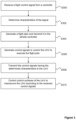
wobei der Server konfiguriert ist, um die Navigationsdaten in Bezug auf eine Vielzahl von unbemannten Luftfahrzeugen zu verwenden, um Routen für diese Fahrzeuge zu extrapolieren, wobei die Durchführung der Routenkonfliktbeseitigung das Erzeugen einer Route für ein unbemanntes Luftfahrzeug umfasst, die keine der extrapolierten Routen kreuzt. - Verfahren zum Steuern eines unbemannten Fahrzeugs (20), das Verfahren umfassend:Abfangen (S300) eines ersten Steuersignals von einer für das unbemannte Luftfahrzeug vorgesehenen Fernsteuerung (10);Speichern einer Route, der das unbemannte Luftfahrzeug folgen soll;Bestimmen (S302) von Eigenschaften des ersten Steuersignals;Erzeugen (S306) eines zweiten Steuersignals, wobei das zweite Steuersignal eine Anweisung für das unbemannte Luftfahrzeug umfasst, ein Manöver durchzuführen, um der Route zu folgen; und,Senden (S308) des zweiten Steuersignals, das eingerichtet ist, um die bestimmten Eigenschaften aufzuweisen, an das unbemannte Luftfahrzeug,wobei das Verfahren ferner das Empfangen einer Vielzahl von Routen, das Bestimmen der Route, der das unbemannte Luftfahrzeug folgen soll, durch Durchführen der Routenkonfliktbeseitigung auf der Vielzahl von Routen und das Speichern der bestimmten Route umfasst.
- Verfahren nach Anspruch 12, umfassend das Bestimmen der Frequenz und/oder des Kanals, auf der/dem das erste Steuersignal gesendet wurde.
- Verfahren nach Anspruch 12 oder 13, umfassend das Bestimmen der Route, der das Fahrzeug folgen soll, durch Durchführen der Routenkonfliktbeseitigung auf einer Vielzahl von Routen und das Speichern der bestimmten Route.
Applications Claiming Priority (2)
| Application Number | Priority Date | Filing Date | Title |
|---|---|---|---|
| GB2012397.2A GB2597936B (en) | 2020-08-10 | 2020-08-10 | Vehicle controller |
| PCT/GB2021/051867 WO2022034282A1 (en) | 2020-08-10 | 2021-07-21 | An apparatus for controlling an unmanned vehicle and a method of controlling an unmanned vehicle |
Publications (3)
| Publication Number | Publication Date |
|---|---|
| EP4193232A1 EP4193232A1 (de) | 2023-06-14 |
| EP4193232C0 EP4193232C0 (de) | 2025-04-02 |
| EP4193232B1 true EP4193232B1 (de) | 2025-04-02 |
Family
ID=72519911
Family Applications (2)
| Application Number | Title | Priority Date | Filing Date |
|---|---|---|---|
| EP21730642.2A Active EP4193231B8 (de) | 2020-08-10 | 2021-05-21 | Fahrzeugsteuerung |
| EP21749268.5A Active EP4193232B1 (de) | 2020-08-10 | 2021-07-21 | Fahrzeugsteuerung |
Family Applications Before (1)
| Application Number | Title | Priority Date | Filing Date |
|---|---|---|---|
| EP21730642.2A Active EP4193231B8 (de) | 2020-08-10 | 2021-05-21 | Fahrzeugsteuerung |
Country Status (5)
| Country | Link |
|---|---|
| US (2) | US20230290257A1 (de) |
| EP (2) | EP4193231B8 (de) |
| ES (2) | ES3022207T3 (de) |
| GB (2) | GB2597936B (de) |
| WO (2) | WO2022034278A1 (de) |
Families Citing this family (2)
| Publication number | Priority date | Publication date | Assignee | Title |
|---|---|---|---|---|
| EP3341925B1 (de) * | 2015-08-27 | 2023-09-13 | Dronsystems Limited | Hochautomatisiertes system für flugverkehrskontrolle (atm) für mindestens ein unbemanntes luftfahrzeug (unbemannte luftfahrzeuge uav) |
| US20240177613A1 (en) * | 2022-11-28 | 2024-05-30 | Zing Drone Delivery Inc. | Remote id conflict system |
Family Cites Families (21)
| Publication number | Priority date | Publication date | Assignee | Title |
|---|---|---|---|---|
| US9014874B2 (en) * | 2013-01-29 | 2015-04-21 | Foster-Miller, Inc. | Tactical robot controller |
| US9760094B2 (en) * | 2014-10-08 | 2017-09-12 | The Boeing Company | Distributed collaborative operations processor systems and methods |
| NO339419B1 (en) * | 2015-03-25 | 2016-12-12 | FLIR Unmanned Aerial Systems AS | Path-Based Flight Maneuvering System |
| EP3341925B1 (de) * | 2015-08-27 | 2023-09-13 | Dronsystems Limited | Hochautomatisiertes system für flugverkehrskontrolle (atm) für mindestens ein unbemanntes luftfahrzeug (unbemannte luftfahrzeuge uav) |
| US11017680B2 (en) * | 2015-09-30 | 2021-05-25 | Alarm.Com Incorporated | Drone detection systems |
| WO2017125916A1 (en) * | 2016-01-19 | 2017-07-27 | Vision Cortex Ltd | Method and system for emulating modular agnostic control of commercial unmanned aerial vehicles (uavs) |
| US20170255580A1 (en) * | 2016-03-02 | 2017-09-07 | Northrop Grumman Systems Corporation | Multi-modal input system for a computer system |
| US9990854B1 (en) * | 2016-03-15 | 2018-06-05 | Rockwell Collins, Inc. | Unmanned aerial system mission flight representation conversion techniques and traffic management scheme |
| JP6020872B1 (ja) * | 2016-06-24 | 2016-11-02 | 株式会社アドインテ | 分析システム及び分析方法 |
| GB2546438B (en) * | 2016-09-19 | 2018-08-08 | Citadel Defense Company | Radio control transmissions |
| CN107636552A (zh) * | 2016-09-27 | 2018-01-26 | 深圳市大疆创新科技有限公司 | 一种飞行控制方法及装置、控制设备 |
| US10019002B2 (en) * | 2016-10-13 | 2018-07-10 | Navico Holding As | Unmanned vehicle control and operation in a marine environment |
| WO2018129612A1 (en) * | 2017-01-10 | 2018-07-19 | AIRSHARE, Inc. | System and method for communicating with a uav |
| US10649469B2 (en) * | 2017-01-19 | 2020-05-12 | Vtrus Inc. | Indoor mapping and modular control for UAVs and other autonomous vehicles, and associated systems and methods |
| KR101897597B1 (ko) * | 2017-06-19 | 2018-09-13 | 주식회사 스카이텍 | 드론 조종을 위한 리모트 컨트롤러 연결 시스템 |
| US20200110424A1 (en) * | 2018-10-03 | 2020-04-09 | Real Estate Portal Usa Llc | Geofencing of unmanned aerial vehicles |
| JP2020102679A (ja) * | 2018-12-20 | 2020-07-02 | ソフトバンク株式会社 | 通信装置、方法及びプログラム、並びに、その通信装置を有する飛行装置及び制御システム |
| US11409291B2 (en) * | 2019-03-21 | 2022-08-09 | Performance Drone Works Llc | Modular autonomous drone |
| US11099583B2 (en) * | 2019-05-10 | 2021-08-24 | Wing Aviation Llc | Real-time optimization of autonomous vehicle routes |
| US11410562B1 (en) * | 2019-08-14 | 2022-08-09 | Amazon Technologies, Inc. | Aerial vehicle travel related data collection and route optimization |
| WO2021046026A1 (en) * | 2019-09-02 | 2021-03-11 | Skygrid, Llc | Parallel deconfliction processing of unmanned aerial vehicles |
-
2020
- 2020-08-10 GB GB2012397.2A patent/GB2597936B/en active Active
-
2021
- 2021-05-21 GB GB2107278.0A patent/GB2601023B/en active Active
- 2021-05-21 ES ES21730642T patent/ES3022207T3/es active Active
- 2021-05-21 WO PCT/GB2021/051235 patent/WO2022034278A1/en not_active Ceased
- 2021-05-21 US US18/020,311 patent/US20230290257A1/en active Pending
- 2021-05-21 EP EP21730642.2A patent/EP4193231B8/de active Active
- 2021-07-21 ES ES21749268T patent/ES3025475T3/es active Active
- 2021-07-21 US US18/020,321 patent/US20230305558A1/en active Pending
- 2021-07-21 EP EP21749268.5A patent/EP4193232B1/de active Active
- 2021-07-21 WO PCT/GB2021/051867 patent/WO2022034282A1/en not_active Ceased
Also Published As
| Publication number | Publication date |
|---|---|
| GB202107278D0 (en) | 2021-07-07 |
| EP4193232C0 (de) | 2025-04-02 |
| WO2022034282A1 (en) | 2022-02-17 |
| EP4193231B1 (de) | 2025-02-26 |
| EP4193231A1 (de) | 2023-06-14 |
| EP4193231B8 (de) | 2025-04-09 |
| ES3025475T3 (en) | 2025-06-09 |
| EP4193231C0 (de) | 2025-02-26 |
| GB2601023A (en) | 2022-05-18 |
| US20230305558A1 (en) | 2023-09-28 |
| GB202012397D0 (en) | 2020-09-23 |
| WO2022034278A1 (en) | 2022-02-17 |
| GB2597936B (en) | 2024-03-20 |
| EP4193232A1 (de) | 2023-06-14 |
| GB2597936A (en) | 2022-02-16 |
| ES3022207T3 (en) | 2025-05-28 |
| GB2601023B (en) | 2024-10-30 |
| US20230290257A1 (en) | 2023-09-14 |
Similar Documents
| Publication | Publication Date | Title |
|---|---|---|
| EP3717352B1 (de) | Autonomes unbemanntes luftfahrzeug und steuerungsverfahren dafür | |
| US11900823B2 (en) | Systems and methods for computing flight controls for vehicle landing | |
| KR101990886B1 (ko) | 빅데이터 기반 자율 비행 드론 시스템 및 그 자율 비행 방법 | |
| CN108615346B (zh) | 中继无人机系统 | |
| EP3619112B1 (de) | Relaisdrohnenverfahren | |
| US8626361B2 (en) | System and methods for unmanned aerial vehicle navigation | |
| EP2177966B1 (de) | Systeme und Verfahren zur Navigation eines unbemannten Luftfahrzeugs | |
| US10502584B1 (en) | Mission monitor and controller for autonomous unmanned vehicles | |
| EP3538966B1 (de) | Fahrzeugkollisionsvermeidung | |
| JP7253315B2 (ja) | 航空機の飛行支援システム、航空機の飛行支援プログラム及び航空機 | |
| EP3608633B1 (de) | System und verfahren zum führen eines fahrzeugs entlang eines fahrweges | |
| US20220309931A1 (en) | Systems and methods for guiding vehicles to charging points | |
| EP4193232B1 (de) | Fahrzeugsteuerung | |
| JP2023029358A (ja) | 自動管制システム、自動管制方法、及び自動管制装置 | |
| WO2025102024A1 (en) | Uav route planning for mitigating traffic encounters | |
| US12269610B2 (en) | Systems and methods for providing safe landing assistance for an aerial vehicle | |
| US20220343779A1 (en) | System, device and method for time limited communication for remotely controlled vehicles | |
| WO2025088470A1 (en) | Aircraft systems | |
| HK40010978A (en) | Autonomous unmanned aerial vehicle and method of control thereof |
Legal Events
| Date | Code | Title | Description |
|---|---|---|---|
| STAA | Information on the status of an ep patent application or granted ep patent |
Free format text: STATUS: UNKNOWN |
|
| STAA | Information on the status of an ep patent application or granted ep patent |
Free format text: STATUS: THE INTERNATIONAL PUBLICATION HAS BEEN MADE |
|
| PUAI | Public reference made under article 153(3) epc to a published international application that has entered the european phase |
Free format text: ORIGINAL CODE: 0009012 |
|
| STAA | Information on the status of an ep patent application or granted ep patent |
Free format text: STATUS: REQUEST FOR EXAMINATION WAS MADE |
|
| 17P | Request for examination filed |
Effective date: 20230228 |
|
| AK | Designated contracting states |
Kind code of ref document: A1 Designated state(s): AL AT BE BG CH CY CZ DE DK EE ES FI FR GB GR HR HU IE IS IT LI LT LU LV MC MK MT NL NO PL PT RO RS SE SI SK SM TR |
|
| DAV | Request for validation of the european patent (deleted) | ||
| DAX | Request for extension of the european patent (deleted) | ||
| STAA | Information on the status of an ep patent application or granted ep patent |
Free format text: STATUS: EXAMINATION IS IN PROGRESS |
|
| 17Q | First examination report despatched |
Effective date: 20240405 |
|
| REG | Reference to a national code |
Ref country code: DE Ref legal event code: R079 Free format text: PREVIOUS MAIN CLASS: G05D0001100000 Ipc: G05D0001000000 Ref document number: 602021028548 Country of ref document: DE |
|
| GRAP | Despatch of communication of intention to grant a patent |
Free format text: ORIGINAL CODE: EPIDOSNIGR1 |
|
| STAA | Information on the status of an ep patent application or granted ep patent |
Free format text: STATUS: GRANT OF PATENT IS INTENDED |
|
| RIC1 | Information provided on ipc code assigned before grant |
Ipc: G08G 5/00 20060101ALI20241225BHEP Ipc: G08G 5/04 20060101ALI20241225BHEP Ipc: G05D 1/00 20060101AFI20241225BHEP |
|
| GRAS | Grant fee paid |
Free format text: ORIGINAL CODE: EPIDOSNIGR3 |
|
| INTG | Intention to grant announced |
Effective date: 20250124 |
|
| GRAA | (expected) grant |
Free format text: ORIGINAL CODE: 0009210 |
|
| STAA | Information on the status of an ep patent application or granted ep patent |
Free format text: STATUS: THE PATENT HAS BEEN GRANTED |
|
| RIC1 | Information provided on ipc code assigned before grant |
Ipc: G08G 5/00 20060101ALI20250128BHEP Ipc: G05D 1/00 20060101AFI20250128BHEP |
|
| AK | Designated contracting states |
Kind code of ref document: B1 Designated state(s): AL AT BE BG CH CY CZ DE DK EE ES FI FR GB GR HR HU IE IS IT LI LT LU LV MC MK MT NL NO PL PT RO RS SE SI SK SM TR |
|
| REG | Reference to a national code |
Ref country code: GB Ref legal event code: FG4D |
|
| REG | Reference to a national code |
Ref country code: CH Ref legal event code: EP |
|
| REG | Reference to a national code |
Ref country code: IE Ref legal event code: FG4D |
|
| REG | Reference to a national code |
Ref country code: DE Ref legal event code: R096 Ref document number: 602021028548 Country of ref document: DE |
|
| U01 | Request for unitary effect filed |
Effective date: 20250428 |
|
| U07 | Unitary effect registered |
Designated state(s): AT BE BG DE DK EE FI FR IT LT LU LV MT NL PT RO SE SI Effective date: 20250506 |
|
| REG | Reference to a national code |
Ref country code: ES Ref legal event code: FG2A Ref document number: 3025475 Country of ref document: ES Kind code of ref document: T3 Effective date: 20250609 |
|
| PGFP | Annual fee paid to national office [announced via postgrant information from national office to epo] |
Ref country code: GB Payment date: 20250619 Year of fee payment: 5 |
|
| U20 | Renewal fee for the european patent with unitary effect paid |
Year of fee payment: 5 Effective date: 20250620 |
|
| PGFP | Annual fee paid to national office [announced via postgrant information from national office to epo] |
Ref country code: ES Payment date: 20250801 Year of fee payment: 5 |
|
| PG25 | Lapsed in a contracting state [announced via postgrant information from national office to epo] |
Ref country code: GR Free format text: LAPSE BECAUSE OF FAILURE TO SUBMIT A TRANSLATION OF THE DESCRIPTION OR TO PAY THE FEE WITHIN THE PRESCRIBED TIME-LIMIT Effective date: 20250703 Ref country code: NO Free format text: LAPSE BECAUSE OF FAILURE TO SUBMIT A TRANSLATION OF THE DESCRIPTION OR TO PAY THE FEE WITHIN THE PRESCRIBED TIME-LIMIT Effective date: 20250702 |
|
| PG25 | Lapsed in a contracting state [announced via postgrant information from national office to epo] |
Ref country code: PL Free format text: LAPSE BECAUSE OF FAILURE TO SUBMIT A TRANSLATION OF THE DESCRIPTION OR TO PAY THE FEE WITHIN THE PRESCRIBED TIME-LIMIT Effective date: 20250402 |
|
| PG25 | Lapsed in a contracting state [announced via postgrant information from national office to epo] |
Ref country code: HR Free format text: LAPSE BECAUSE OF FAILURE TO SUBMIT A TRANSLATION OF THE DESCRIPTION OR TO PAY THE FEE WITHIN THE PRESCRIBED TIME-LIMIT Effective date: 20250402 |
|
| PG25 | Lapsed in a contracting state [announced via postgrant information from national office to epo] |
Ref country code: RS Free format text: LAPSE BECAUSE OF FAILURE TO SUBMIT A TRANSLATION OF THE DESCRIPTION OR TO PAY THE FEE WITHIN THE PRESCRIBED TIME-LIMIT Effective date: 20250702 |
|
| PG25 | Lapsed in a contracting state [announced via postgrant information from national office to epo] |
Ref country code: IS Free format text: LAPSE BECAUSE OF FAILURE TO SUBMIT A TRANSLATION OF THE DESCRIPTION OR TO PAY THE FEE WITHIN THE PRESCRIBED TIME-LIMIT Effective date: 20250802 |
|
| PG25 | Lapsed in a contracting state [announced via postgrant information from national office to epo] |
Ref country code: SM Free format text: LAPSE BECAUSE OF FAILURE TO SUBMIT A TRANSLATION OF THE DESCRIPTION OR TO PAY THE FEE WITHIN THE PRESCRIBED TIME-LIMIT Effective date: 20250402 |
|
| PG25 | Lapsed in a contracting state [announced via postgrant information from national office to epo] |
Ref country code: CZ Free format text: LAPSE BECAUSE OF FAILURE TO SUBMIT A TRANSLATION OF THE DESCRIPTION OR TO PAY THE FEE WITHIN THE PRESCRIBED TIME-LIMIT Effective date: 20250402 |
|
| PG25 | Lapsed in a contracting state [announced via postgrant information from national office to epo] |
Ref country code: SK Free format text: LAPSE BECAUSE OF FAILURE TO SUBMIT A TRANSLATION OF THE DESCRIPTION OR TO PAY THE FEE WITHIN THE PRESCRIBED TIME-LIMIT Effective date: 20250402 |
|
| PLBE | No opposition filed within time limit |
Free format text: ORIGINAL CODE: 0009261 |
|
| STAA | Information on the status of an ep patent application or granted ep patent |
Free format text: STATUS: NO OPPOSITION FILED WITHIN TIME LIMIT |
|
| REG | Reference to a national code |
Ref country code: CH Ref legal event code: L10 Free format text: ST27 STATUS EVENT CODE: U-0-0-L10-L00 (AS PROVIDED BY THE NATIONAL OFFICE) Effective date: 20260211 |