EP4193120B1 - Distortion-corrected phase generated carrier demodulation method using multitone mixing - Google Patents
Distortion-corrected phase generated carrier demodulation method using multitone mixing Download PDFInfo
- Publication number
- EP4193120B1 EP4193120B1 EP21743531.2A EP21743531A EP4193120B1 EP 4193120 B1 EP4193120 B1 EP 4193120B1 EP 21743531 A EP21743531 A EP 21743531A EP 4193120 B1 EP4193120 B1 EP 4193120B1
- Authority
- EP
- European Patent Office
- Prior art keywords
- cos
- interferometer
- pgc
- branches
- mtm
- Prior art date
- Legal status (The legal status is an assumption and is not a legal conclusion. Google has not performed a legal analysis and makes no representation as to the accuracy of the status listed.)
- Active
Links
Images



Classifications
-
- G—PHYSICS
- G01—MEASURING; TESTING
- G01B—MEASURING LENGTH, THICKNESS OR SIMILAR LINEAR DIMENSIONS; MEASURING ANGLES; MEASURING AREAS; MEASURING IRREGULARITIES OF SURFACES OR CONTOURS
- G01B9/00—Measuring instruments characterised by the use of optical techniques
- G01B9/02—Interferometers
- G01B9/02083—Interferometers characterised by particular signal processing and presentation
-
- H—ELECTRICITY
- H04—ELECTRIC COMMUNICATION TECHNIQUE
- H04L—TRANSMISSION OF DIGITAL INFORMATION, e.g. TELEGRAPHIC COMMUNICATION
- H04L27/00—Modulated-carrier systems
- H04L27/18—Phase-modulated carrier systems, i.e. using phase-shift keying
- H04L27/22—Demodulator circuits; Receiver circuits
Definitions
- the present invention relates to a distortion-corrected Phase Generated Carrier Demodulation Method using Multitone Mixing.
- Interferometers can detect the phase difference between two optical branches, and from this information one can measure remarkably small displacements or wavelength variations.
- the latter method is the most popular, and consists in introducing a sinusoidal modulation in the interferometer, and extracting the cosine (in-phase, I ) and the sine (quadrature, Q ) components from the different harmonics (most typically the first and the second) of the extracted signals.
- I in-phase
- Q sine
- the phase can be calculated either by applying an arc-tangent function [6] or a cross-difference multiplication algorithm (CDM) [5].
- the cross-difference multiplication method has the main disadvantage that it only calculates the derivative of the signal, which makes it more sensitive to low-frequency noise, and prevents the calculation of the absolute phase value. Furthermore, even though it is less prone to distortion than the arc-tangent method, it is sensitive to light intensity fluctuations. In contrast, the arc-tangent method allows the calculation of the absolute phase and is intrinsically robust to light intensity fluctuations [6].
- the main disadvantage of the arc-tan methods is the distortion generated when the modulation depth deviates from the nominal one, which deforms the IQ circumference into an ellipse. Renormalizing the ellipse back into a circumference is possible, but in real systems the modulation depth can drift, and in these cases, it is not straightforward to track and update the correction algorithms.
- the object of the present invention is to provide a demodulation method for optical interferometry which at least in part solves the problems and overcomes the disadvantages of the prior art.
- the subject-matter of the present invention is a method and a corresponding program and interferometric system according to the attached claims.
- CMOS complementary metal-oxide-semiconductor
- CMOS complementary metal-oxide-semiconductor
- invention can be implemented also on other types of hardware, such as analogic or digital circuity or (non-programmable) logic, such as a lock-in amplification circuit.
- MTM multitone mixing
- the invention concept comes from the fact that nowadays signal processing is mostly done in the digital domain. This means that mixers are digital multiplications, rather than the result of mixing two analog signals in a nonlinear medium.
- mixing with a sinusoidal waveform is typically performed by digitally multiplying the input signal by the analytic sinusoidal function, extracted from a look-up table or from a trigonometric function calculation.
- mixing with an arbitrary function different from a sinusoidal does not necessarily complicate the system, as it only implies a different look-up table to generate the reference waveform.
- the reference signal is a linear combination of two frequencies
- the dependence on the modulation depth is determined by the equivalent linear combination of Bessel functions of the first kind. The inventors found that when the parameters of the linear combination are chosen to match the first and even the second derivatives of the IQ components with respect to the modulation depth, the distortion can be dramatically reduced in presence of variations of the modulation depth.
- J i represents the Bessel function of the first kind. This means that the I component of the signal, proportional to the cosine of the phase, can be extracted from the even frequency components of the signal, while the Q component can be extracted from the odd frequency components.
- C 0.84 ⁇ (value with the least noise, however any value can be used with the invention method)
- the Bessel functions coincide and the signals I ⁇ and I 2 ⁇ fall into a circumference when plotted in orthogonal axes.
- the concept of the invention here disclosed is to use a linear combination of the first few harmonics in order to generate functions with a distortion parameter ⁇ to have a zero derivative with C , so that distortion will be reduced to the minimum for small variations of C.
- phase ⁇ ⁇ ( t ) ⁇ ⁇ MTM (t) (MTM stands for "Multitone Mixing" according to the invention) from the ratio of the mixing with functions f 1 and f 2 :
- the distortion from this method will be determined by the variation of the quotient S 1 / S 2 , which is our new distortion coefficient ⁇ MTM :
- Fig. 2 shows the evolution of the distortion parameter ⁇ versus variations of the modulation depth with respect to the nominal value, applying the standard PGC and the MTM approach up to 3 ⁇ and up to 4 ⁇ . It is clear that both MTM methods are much more robust to modulation depth variations; in particular, the case up to 4 ⁇ has an even wider range, as expected, due to the extra condition cancelling the second derivative ⁇ " (C) .
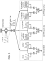
- Fig. 3 shows a system of a generic interferometer with active phase demodulation using three different PGC schemes: the standard PGC ( Fig. 3(a) ), the MTM up to 3 ⁇ ( Fig. 3(b) ) and up to 4 ⁇ ( Fig. 3(c) ).
- the interferometer shown in this figure is a Mach-Zehnder type, but the method can be applied to other types of interferometers, such as the Michelson's.
- the method above described can be generalized to an undefined number of harmonics.
- ⁇ C ⁇ j ⁇ 1 j a 2 j ⁇ 1 J 2 j ⁇ 1 C ⁇ k ⁇ 1 k + 1 a 2 k J 2 k C
- THD total harmonic distortion
- SINAD signal-to-noise and distortion ratio
- THD quantifies the effect of the modulation depth deviation on the distortion of the demodulated signal
- SINAD not only measures the effect of the distortion, but also considers the effect of the presence of noise in the demodulated signal.
- C nom 0.84 ⁇
- the deviation of C mod from the nominal value increases, so does the THD for all the PGC methods; however, since the variation of ⁇ with respect to C mod is much larger for PGC-std than for the proposed algorithms (see Fig.
- Fig. 5 we show the power spectral density of the demodulated signals at different modulation depths.
- the SINAD is better for PGC-std, followed by PGC-MTM up to 3 ⁇ , as shown in Fig. 5(a)
- the MTM method can be applied to a variety of interferometers in which the phase can be modulated externally.
- the phase can be modulated in one of the arms using a piezoelectric actuator, like in the case of some fiber-optic based interferometers (FOIs) [7], or through thermo-optic effect [22], carrier injection/depletion or other phase shifting mechanisms in photonic integrated circuit-based interferometers.
- the method can also be applied modulating the optical source [23], but in this case the interferometer must be unbalanced, so that wavelength changes are converted into phase variations.
- the first application is a wavemetering experiment using an unbalanced MZI on SiPh platform, fabricated at CEA-Leti with deep-UV lithography, [22].
- MMI multimode interference
- each MZI included phase modulator based on the thermo-optic effect, consisting of a metal Ti/TiN heater track with length of 86 ⁇ m and width of 1.43 ⁇ m, with a V ⁇ p-p of 3.69 V, and a 1/ e time constant of 7 ⁇ s.
- Each MZI has an output grating coupler for coupling to external photoreceivers.
- Both MZI configurations included a thermal modulator to allow the implementation of the PGC technique. Both chips include two MZIs with different spiral lengths sharing the same input. For our experiments we used the MZIs with longer spirals, so called fine, that provide a higher responsivity than the ones with shorter spirals, so called coarse [22].
- the schematic of the experimental setup is shown in Fig. 6 .
- the integrated unbalanced MZI is employed as a wavemeter to measure a wavelength shift generated using a tunable external cavity laser model EXFO T100S-HP (output power set to 10mW).
- the phase modulator of the MZI was driven using the square-root of a sinusoidal signal at 1 kHz, since the power on the thermal phase shifter is proportional to the square of the applied voltage.
- the output of the interferometer was coupled to an external InGaAs based photoreceiver with a responsivity of ⁇ 5 ⁇ 10 4 V/W and 775 kHz bandwidth.
- the traces were collected with a 16-bit data acquisition card model MCDAQ USB-1608FS at 100kS/s. Additionally, we compared the measurements with the commercial wavemeter model I-MON 512 USB from Ibsen Photonics A/S.
- Fig. 7(a) shows the demodulated trances in the whole measuring range and Fig. 7(b) shows a zoom of the measurement.
- the PGC-std algorithm has visible non-linearities in the form of an undulation that occurs every ⁇ /2 shift, or every quarter of the free spectral range of the MZI, whereas for PGC-MTM up to 3 ⁇ and up to 4 ⁇ there are no visible non-linearities when compared to the trace obtained with the commercial wavemeter, demonstrating the robustness of the PGC-MTM algorithms to modulation depth deviations.
- the second application is refractrometry measurements using a balanced MZI-based chemical sensor on SiPh platform fabricated at InPhoTec facilities using e-beam lithography (design details can be found in [24]).
- the results of the chemical sensor are shown in Fig. 9 , with a comparison of the results using PGC-std and PGC-MTM up to 3 ⁇ (sensitivity 1.31 ⁇ 10 6 deg/RIU) .
- a deionized water (DIW) baseline and the injection of a glycerol aqueous solution at 1% volume concentration (see inset in Fig. 9 ).
- the invention method is a novel active phase demodulation technique for optical interferometers which strongly reduces distortion under deviations of the modulation depth. These deviations can originate from thermal fluctuations, or other external effects. In addition, tolerance to modulation depth variation would also be necessary when one single driving source is used to modulate different interferometers with slightly different characteristics.
- another application of this scheme is a situation in which a single interferometer is used to measure the signal coming from different transducers simultaneously using a wavelength-division multiplexing (WDM) scheme. Dispersion effects may generate a difference in the voltage needed to generate a certain phase shift for each transducer. In this case, C cannot be the same for every channel, which would generate distortion in the channels where C deviates from the nominal value.
- the multitone mixing scheme proposed here would strongly reduce the distortion in these channels because the system would be much more tolerant to deviations from the nominal modulation depth C 0 .
- the technique called multitone mixing, consists in mixing the output waveform with linear combinations of even and odd harmonics of the modulating frequency, and choosing the coefficients to cancel the first and possibly the successive derivatives of the distortion parameter ⁇ .
- the technique has several advantages with respect to previous proposed solutions, in particular, not requiring signal variations, ellipse fitting algorithms, or recording previous data, it can determine the DC component of the phase.
- the technique is also experimentally validated with a wavelength metering integrated interferometer and a chemical sensing experiment, and shows no noise penalty with respect to the standard PGC technique.
Landscapes
- Engineering & Computer Science (AREA)
- Signal Processing (AREA)
- Physics & Mathematics (AREA)
- General Physics & Mathematics (AREA)
- Computer Networks & Wireless Communication (AREA)
- Instruments For Measurement Of Length By Optical Means (AREA)
- Digital Transmission Methods That Use Modulated Carrier Waves (AREA)
Description
- The present invention relates to a distortion-corrected Phase Generated Carrier Demodulation Method using Multitone Mixing.
- Optical interferometry is currently the most accurate technique to measure certain physical magnitudes such as displacement, vibrations, wavelength, among others. Interferometers can detect the phase difference between two optical branches, and from this information one can measure remarkably small displacements or wavelength variations.
- In a homodyne interferometer, when the two optical beams with the same frequency recombine after following different paths, the resulting signal is modulated by the cosine of their phase difference, which can be used to extract the phase change. However, the problem is that the slope of the cosine function, which determines the responsivity, varies periodically with the phase itself, generating so-called responsivity fading. The point of maximum slope is known as the quadrature point, and it is not straightforward to keep the interferometer always in quadrature. Many techniques exist for solving this problem, such as the use of 3x3 beam couplers at the output [1] which generates three signals dephased by 120°, allowing the univocal extraction of the phase with no responsivity fading, but this technique requires monitoring three signal ports per sensing point, and requires a previous calibration. Other techniques apply active modulation of the interferometer, either to keep it in quadrature with a feedback loop [2] or dithering it constantly and applying phase demodulation techniques such as pseudo-heterodyne [3], serrodyne modulation with quadrature sampling [4] or phase generated carrier (PGC) modulation [5]. The latter method is the most popular, and consists in introducing a sinusoidal modulation in the interferometer, and extracting the cosine (in-phase, I) and the sine (quadrature, Q) components from the different harmonics (most typically the first and the second) of the extracted signals. Once the I and the Q are known, the phase can be calculated either by applying an arc-tangent function [6] or a cross-difference multiplication algorithm (CDM) [5].
- The cross-difference multiplication method has the main disadvantage that it only calculates the derivative of the signal, which makes it more sensitive to low-frequency noise, and prevents the calculation of the absolute phase value. Furthermore, even though it is less prone to distortion than the arc-tangent method, it is sensitive to light intensity fluctuations. In contrast, the arc-tangent method allows the calculation of the absolute phase and is intrinsically robust to light intensity fluctuations [6]. The main disadvantage of the arc-tan methods is the distortion generated when the modulation depth deviates from the nominal one, which deforms the IQ circumference into an ellipse. Renormalizing the ellipse back into a circumference is possible, but in real systems the modulation depth can drift, and in these cases, it is not straightforward to track and update the correction algorithms.
- Many different works have been published to correct distortion in PGC algorithms. Some methods use correction factors which are used to renormalize the I and Q signals [7] [8] [9] [10]. However, these methods have the drawback of having situations in which a division by zero may occur, which strongly increases noise; in addition, they often require a phase variation in time to be effective. Other methods monitor higher harmonics of the signal, 3f [11] [12] [13] and sometimes up to 4f [14] [15], but these methods also generate divisions by zero when the phase is close to certain values, which generates noise. Other techniques use ellipse-fitting algorithms to characterize the deviation from the nominal modulation depth [16] [17] but they require a calibration process every time the modulation depth changes, or require a reference interferometer. They also require a variation of the signal along a certain range for the calibration to take place. In [18], a sophisticated arc tan-based method is presented, which is robust to modulation depth, light intensity noise and phase delay variations.
- However, this method requires a complex signal analysis using 8 different mixers for every signal to demodulate. In "An ameliorated phase-generated-carrier demodulation algorithm for sinusoidal phase-modulating fiber-optic interferometer" by LI SHUWANG ET AL a method for demodulating a waveform I outputting from an interferometer with two branches according to the state of the art is disclosed.
- The object of the present invention is to provide a demodulation method for optical interferometry which at least in part solves the problems and overcomes the disadvantages of the prior art.
- The subject-matter of the present invention is a method and a corresponding program and interferometric system according to the attached claims.
- The invention will now be described for illustrative but not limitative purposes, with particular reference to the drawings of the attached figures, in which:
-
Fig. 1 shows first four Bessel functions of the first kind and coefficients S1 and S2 versus the normalized modulation depth C/π for the case without 4ω, and the nominal modulation depth C = 0.84π. J1 and J2 have the same the value but not the same slope, while S1 and S2 have the same value and slope; -
Fig. 2 shows a plot of υ versus the normalized modulation depth C/π for standard PGC (PGC-std), PGC-MTM up to 3ω and PGC-MTM up to 4ω; -
Fig. 3 shows an interferometer with PGC active phase demodulation using three techniques: (a) Standard PGC, (b) MTM up to 3ω, (c) MTM up to 4ω. (b) and (c) are the schemes proposed in this work. The waveforms shown are the solutions for the nominal modulation depth C = 0.84π. MTM: Multitone mixing, PM: Phase modulator, PD: photodiode, ADC: analog-to-digital converter, LPF: low-pass filter, ΔL: path difference between the interferometer arms; -
Fig. 4 shows: (a) total harmonic distortion when C deviates from the nominal value Cnom = 0.84π, extracted from the simulated data, for the three described demodulation techniques: standard (blue), MTM up to 3ω (orange), and MTM up to 4 ω. (b) Signal to noise and distortion ratio (SINAD) under the same conditions, introducing an artificial noise in the detected signal with σ = 0.01; -
Fig. 5 shows a comparison of the spectrum between PGC-MTM up to 3ω and PGC-MTM up to 4ω for: (a) Cnom = Cmod = 0.84π and (b) Cnom = 0.84π, Cmod = 0.86π, and between PGC-MTM up to 3ω and PGC-MTM up to 4ω for:(c) Cnom = Cmod =1.11π, and (d) Cnom = Cmod =1.3π; -
Fig. 6 shows a general PGC schematic for demodulating the output of an integrated MZI. TLS: tunable laser; PM: phase modulator; PD: photodetector; ADC: analog-to-digital converter; LPF: low-pass filter; -
Fig. 7 shows a comparison of the results of the wavelength shift measurement between PGC-std, the proposed PGC-MTM algorithms and a commercial wavemeter by IBSEN when Cnom = 0.84π and Cmod = 0.97π. (a) View of the whole wavelength sweep. (b) Zoom of the measurement where it can be appreciated the non-linearity in the result of the PGC-std, which is absent in the traces obtained using the PGC-MTM algorithms and the IBSEN; -
Fig. 8 shows a comparison of the noise level of the demodulated signals for Cnom =Cmod =0.84π with (a) PGC-std, (b) PGC-MTM up to 3ω and (c) PGC-MTM up to 4ω, and for Cnom = 0.84π and Cmod =1.16π with (d) PGC-MTM up to 3ω and (e) PGC-MTM up to 4ω; and -
Fig. 9 shows a comparison of the results using PGC-std and PGC-MTM up to 3ω for refractrometry, during the transient caused by the introduction of 1% glycerol concentration in water (sensitivity of the interferometer is 1.31×10⁶ deg/RIU). - It is specified here that elements of different embodiments can be combined together to provide further embodiments without limitations respecting the technical concept of the invention, as the person skilled in the art intends without problems from what has been described.
- The present description further refers to the prior art for its implementation, with respect to the detailed features not described, such as for example elements of lesser importance usually used in the prior art in solutions of the same type.
- When an element is introduced, it is always meant that it can be "at least one" or "one or more".
- When a list of elements or features is listed in this description, it is understood that the invention according to the invention "comprises" or alternatively "is composed of" such elements.
- By "computer" in this application is meant any programmable logic, such as for example a FPGA or a CPU. The invention can be implemented also on other types of hardware, such as analogic or digital circuity or (non-programmable) logic, such as a lock-in amplification circuit.
- In this description, we disclose a method for phase demodulation in a PGC system which we call multitone mixing (MTM), because it involves mixing the signal with synthetic multi-frequency reference waveforms. The method is robust to modulation depth variations and light intensity noise, and is also very simple to implement in a digital signal processing system. The method only requires two mixers, and no calibration is required, which means the correction can take place in real time with no previous data storage and without any signal variation requirement.
- The invention concept comes from the fact that nowadays signal processing is mostly done in the digital domain. This means that mixers are digital multiplications, rather than the result of mixing two analog signals in a nonlinear medium. Thus, mixing with a sinusoidal waveform is typically performed by digitally multiplying the input signal by the analytic sinusoidal function, extracted from a look-up table or from a trigonometric function calculation. As a result, mixing with an arbitrary function different from a sinusoidal does not necessarily complicate the system, as it only implies a different look-up table to generate the reference waveform. When the reference signal is a linear combination of two frequencies, the dependence on the modulation depth is determined by the equivalent linear combination of Bessel functions of the first kind. The inventors found that when the parameters of the linear combination are chosen to match the first and even the second derivatives of the IQ components with respect to the modulation depth, the distortion can be dramatically reduced in presence of variations of the modulation depth.
- To analytically describe the principle, we start with the output of a homodyne interferometer when one of the branches is modulated with a sinusoidal function:

- This signal can be expanded in terms of Bessel functions as [5]:


- The concept of the invention here disclosed is to use a linear combination of the first few harmonics in order to generate functions with a distortion parameter υ to have a zero derivative with C, so that distortion will be reduced to the minimum for small variations of C.
- This can be done by defining two general functions to be used as a reference for the mixing:


- Since these functions are synthetic, we have the freedom to choose the parameters a 1..4 to satisfy the conditions we need in order to minimize distortion. Considering that a global multiplicative number will not affect the quotient f 1/f 2, we can make a 1 = 1, so the only significant parameters become a 2...4. On the other hand, we also have the freedom to decide whether to use the 4th harmonic or not. In this first analysis, we will only consider the first three harmonics, which means that we will force a4 = 0. Later in this description, we will consider the case including the 4th harmonic.
- The case without 4ω can be preferable when the modulation depth is lower, so the amount of signal in the 4th harmonic is close to zero, which means that it could introduce noise in our output signal, as it will be shown below. In this case, by mixing (1) with the multitone signal f 1(t) = cos ωt + a3 cos 3ωt, and the single carrier signal f 2(t) = a2 cos 2ωt, and then low-pass filtering at the baseband, we obtain two signals that are proportional to sin Δϕ(t) and cos Δϕ(t):


- The constraint (8.a) imposes no distortion at the nominal C, and the constraint (8.b) (derivative) keeps distortion to the minimum for small variations around C. Substituting (7.a) and (7.b) in (8.a) and (8.b) we obtain the following matrix equation:

- Therefore, in order to minimize distortion, we only need to solve (9) at the nominal modulation depth C. The derivatives of the Bessel functions can be calculated analytically using the recursive relationship [19]:

- For the nominal modulation depth of C = 0.84π, the solution of (9) is a2 = 2.5806 and a3 = -3.0339, but the equation can be solved for other nominal modulation depths as well. In
Fig. 1 , we show the profiles of functions S 1 (C) and S 2 (C), together with the Bessel functions. It is clear that at the nominal C, S 1 and S 2 not only are equal but also their slopes, as imposed by (8.b). - Now we can calculate the phase Δϕ(t) ≡ ΔϕMTM(t) (MTM stands for "Multitone Mixing" according to the invention) from the ratio of the mixing with functions f1 and f2 :


- This coefficient will undergo a much smaller variation when C deviates from the nominal value, because its first derivative with respect to C is imposed to be zero, as shown in
Fig. 1 . - It is possible to make the PGC-MTM algorithm even more insensitive to the value of the modulation depth by considering f 2(t) = a2 cos 2ωt + a4 cos 4ωt, with a 4 ≠ 0. After mixing and low-pass filtering, the following signals are obtained:


- In this case, having an extra parameter allows us to apply a third condition; therefore, besides making the functions and their first derivatives equal in C, we will force the second derivative to be the same too, which will increase the distortion-free range even further. The conditions are mathematically described below:


- These three equations, when written in matrix form, considering a 1 = 1, become:

- Solving Eq. (15) for the nominal case C = 0.84π, we find the solutions a2 = 4.1936, a3 = -9.7109 and a4 = -9.8913. In this case we have a distortion parameter υMTM equal to:

-
Fig. 2 shows the evolution of the distortion parameter υ versus variations of the modulation depth with respect to the nominal value, applying the standard PGC and the MTM approach up to 3ω and up to 4ω. It is clear that both MTM methods are much more robust to modulation depth variations; in particular, the case up to 4ω has an even wider range, as expected, due to the extra condition cancelling the second derivative υ"(C). -
Fig. 3 shows a system of a generic interferometer with active phase demodulation using three different PGC schemes: the standard PGC (Fig. 3(a) ), the MTM up to 3ω (Fig. 3(b) ) and up to 4ω (Fig. 3(c) ). The waveforms shown correspond to the specific solutions at the nominal modulation depth C = 0.84π, using the solutions for ai coefficients shown above. The interferometer shown in this figure is a Mach-Zehnder type, but the method can be applied to other types of interferometers, such as the Michelson's. - The method above described can be generalized to an undefined number of harmonics.
- The functions f 1(t) and f 2(t) can be written as:




- Where S1(C) = Σ j [(-1) ja 2j-1 J 2j-1(C)] and S 2(C) = Σ j [(-1) j+1 a 2 jJ 2j (C)], therefore the phase shift can be calculated using Eq. (11) above. The matrix system of Eq. (15) is of course extended to j0 + k0 -1 equations, wherein the first row will contain zero-derivative, the second row first derivative, and so on to the last row that will include only (j0 + k0 - 2)-order derivatives of Bessel functions J 2 to Jn wherein n = j0 + k0.
- The same result can be obtained by first generating each harmonic and then performing a linear combination of the products of each harmonic with I. In this case, the phase ϕ can be extracted from the quadrature and in-phase components:


- C0 being the nominal modulation depth; and υ(C) being the distortion parameter defined as:

- This is equivalent to setting conditions on the derivatives of S 1(C) and S 2(C).
- Eq. 21 is valid when the carrier phase delay θ is negligible. In cases in which it is not negligible, a correction factor equal to cos(kθ) must be introduced to every harmonic k [18]. Therefore the more general estimation of distortion in presence of carrier phase delay would be equal to:

- In order to test the method and quantitatively calculate the performance in terms of distortion and noise, we apply the method to a simulated interferometer signal with a sinusoidal waveform in presence of Gaussian noise. The signal at the input of the interferometer is:


- To measure and compare the performance of the PGC algorithms we calculated the total harmonic distortion (THD), defined as the ratio between the equivalent root-mean-square amplitude of all the harmonics and the amplitude of the fundamental frequency of the demodulated signal, given by [20]:


- While THD quantifies the effect of the modulation depth deviation on the distortion of the demodulated signal, SINAD not only measures the effect of the distortion, but also considers the effect of the presence of noise in the demodulated signal.
-
Fig. 4 shows the results for a nominal modulation depth of C nom = 0.84π, which is the value typically used in the standard PGC. For the THD results, the first thing we can see inFig. 4(a) is that when C mod = 0.84π the THD is zero, meaning there is no distortion for any of the algorithms, since in this case the value of υ in (4) is one, cancelling the non-linear term. When the deviation of C mod from the nominal value increases, so does the THD for all the PGC methods; however, since the variation of υ with respect to C mod is much larger for PGC-std than for the proposed algorithms (seeFig. 2 ), its THD is also higher compared to PGC-MTM up to 3ω and PGC-MTM up to 4ω, therefore the proposed algorithms are more robust to modulation depth deviations. Regarding the SINAD, we can see inFig. 4(b) that for the ideal case in which C nom = C mod = 0.84π the SINAD is slightly higher for PGC-std, at 107.1 dB, than for PGC-MTM up to 3ω, however as the deviation of the modulation depth from the nominal value increases, the SINAD for PGD-std rapidly decreases, whereas for PGC-MTM up to 3ω it remains at ~106 dB for C mod between ~0.82π and ~0.85π, meaning that in this range this algorithm is less noisy than PGC-MTM up to 4ω, with a SINAD of ~102 dB. Outside of this range the SINAD rapidly decreases for PGC-MTM up to 3ω, being lower than for PGC-MTM up to 4ω, hence for cases in which the modulation depth deviation is small, it is better to use PGC-MTM up to 3ω, since it is more robust to noise effects than PGC-MTM up to 4ω, and it has a lower THD than PGC-std outside the nominal case. - To further illustrate how distortion and noise affect the acquired signal, in
Fig. 5 we show the power spectral density of the demodulated signals at different modulation depths. For C nom = C mod = 0.84π there is no distortion for any of the PGC algorithms and we can see that the SINAD is better for PGC-std, followed by PGC-MTM up to 3ω, as shown inFig. 5(a) , but a deviation of ~1.2% in the modulation depth from the nominal case (C mod = 0.85π) causes visible distortion in PGC-std, as shown inFig. 5(b) , resulting in a THD = -48.88 dB and SINAD= 48.88 dB, whereas there is still no distortion for the PGC-MTM algorithms.Fig. 5(b) also shows that in this case the SINAD is higher for PGC-MTM up to 3ω than for PGC-MTM up to 4ω, hence the former has a better performance. - Up until this point, we have evaluated the performance of the PGC-MTM algorithms for a nominal modulation depth of C nom = 0.84π, but we can calculate the coefficients of the mixing signals f 1 and f 2 for other nominal values (see sections II.1 and II.2). Evaluating the SINAD for different nominal modulation depths we found that for a value around C nom = 1.11π the SINAD value for PGC-MTM up to 3ω and PGC-MTM up to 4ω is approximately the same, as shown in
Fig. 5(c) , and if we increase C mod even more we can reach a scenario in which the SINAD for the method using up to 4ω is better than for up to 3ω, as shown inFig. 5(d) , showing that in applications when the phase modulator can reach these high modulation depth values, we can obtain a better performance with PGC-MTM up to 4ω, that is comparable to the one obtained with PGC-std for C nom = 0.84π. - In conclusion, these results show that at a nominal modulation depth of 0.84π, which is the one used in the standard PGC, the noise penalty of the MTM method up to 3ω with respect to the standard method is almost negligible (~1dB), while the MTM up to 4ω has a higher penalty (~5dB), which means that the MTM up 3ω is best suited for this modulation depth. However, if our modulator allows applying a higher modulation depth (between 1.11π and 1.3π), the noise penalty of the MTM up to 4ω becomes negligible, making it the best method in terms of distortion and noise.
- In this section we will show experimental results of the proposed invention (MTM) technique compared to the standard PGC scheme. The MTM method can be applied to a variety of interferometers in which the phase can be modulated externally. For instance, the phase can be modulated in one of the arms using a piezoelectric actuator, like in the case of some fiber-optic based interferometers (FOIs) [7], or through thermo-optic effect [22], carrier injection/depletion or other phase shifting mechanisms in photonic integrated circuit-based interferometers. The method can also be applied modulating the optical source [23], but in this case the interferometer must be unbalanced, so that wavelength changes are converted into phase variations.
- For the experimental demonstration we show in the following sections results of the method in two applications.
- The first application is a wavemetering experiment using an unbalanced MZI on SiPh platform, fabricated at CEA-Leti with deep-UV lithography, [22]. This device consists of two MZIs, one with path difference ΔL = 118.6 µm and FSR of 4.8 nm (600 GHz), so called coarse, and another with ΔL = 948.7µm and FSR of 595 pm (75 GHz), so called fine, which share the same input vertical grating coupler through a 2-by-2 multimode interference (MMI) coupler. The shorter arm of each MZI included phase modulator based on the thermo-optic effect, consisting of a metal Ti/TiN heater track with length of 86 µm and width of 1.43 µm, with a Vπ p-p of 3.69 V, and a 1/e time constant of 7 µs. Each MZI has an output grating coupler for coupling to external photoreceivers.
- Both MZI configurations included a thermal modulator to allow the implementation of the PGC technique. Both chips include two MZIs with different spiral lengths sharing the same input. For our experiments we used the MZIs with longer spirals, so called fine, that provide a higher responsivity than the ones with shorter spirals, so called coarse [22].
- The schematic of the experimental setup is shown in
Fig. 6 . In this configuration, the integrated unbalanced MZI is employed as a wavemeter to measure a wavelength shift generated using a tunable external cavity laser model EXFO T100S-HP (output power set to 10mW). In order to apply the PGC algorithms the phase modulator of the MZI was driven using the square-root of a sinusoidal signal at 1 kHz, since the power on the thermal phase shifter is proportional to the square of the applied voltage. The output of the interferometer was coupled to an external InGaAs based photoreceiver with a responsivity of ~5·104 V/W and 775 kHz bandwidth. The traces were collected with a 16-bit data acquisition card model MCDAQ USB-1608FS at 100kS/s. Additionally, we compared the measurements with the commercial wavemeter model I-MON 512 USB from Ibsen Photonics A/S. - To compare the performance of the different PGC algorithms when the modulation depth deviates from the nominal case of C nom = 0.84π we measured a wavelength shift from ~1560 nm to ~1547 nm while applying a modulation depth of C mod = 0.97π to the phase shifter in one of the arms of the MZI.
Fig. 7(a) shows the demodulated trances in the whole measuring range andFig. 7(b) shows a zoom of the measurement. In the latter it can be appreciated that the PGC-std algorithm has visible non-linearities in the form of an undulation that occurs every π/2 shift, or every quarter of the free spectral range of the MZI, whereas for PGC-MTM up to 3ω and up to 4ω there are no visible non-linearities when compared to the trace obtained with the commercial wavemeter, demonstrating the robustness of the PGC-MTM algorithms to modulation depth deviations. - In order to compare the noise levels for the different demodulation schemes, we measured the standard deviation of the signal when the wavelength was fixed. In
Fig. 8 (a-c) we show the noise traces for the standard, MTM up to 3ω, and MTM up to 4ω techniques respectively, for the case in which C nom = C mod = 0.84π, which yielded the minimum noise. From these figures, the standard deviation of the standard and MTM up to 3ω are very similar, 0.116 pm, while the MTM up to 4ω yielded a slightly higher noise of 0.130 pm. An increase in noise with the MTM up to 4ω at this modulation depth was predicted in the previous section. However, the amount of the increase of noise is lower in the experiment than in the simulation (Fig. 4(b) shows ~5dB noise penalty); we attribute this to the contribution of wavelength noise of the source itself, which was not considered in the simulation. - On the other hand,
Fig. 8(d) and (e) show the experimental noise levels when the nominal modulation depth is increased to C nom = C mod = 1.16π (value with the least noise, but other values can be used by the invention method), showing that the noise of the MTM up to 4ω technique is reduced again (down to 0.09 pm), as predicted from the simulation results shown inFig. 5(d) . - These results provide experimental evidence of the fact that distortion can be corrected with the MTM technique, and that the noise does not increase significantly with respect to the standard PGC technique, in particular for the MTM up to 3ω, at C nom = 0.84π, and neither for the even more robust MTM up to 4ω when a higher modulation depth is applied.
- The second application is refractrometry measurements using a balanced MZI-based chemical sensor on SiPh platform fabricated at InPhoTec facilities using e-beam lithography (design details can be found in [24]). The results of the chemical sensor are shown in
Fig. 9 , with a comparison of the results using PGC-std and PGC-MTM up to 3ω (sensitivity 1.31×10⁶ deg/RIU) . In this experiment we measured the phase shift induced by the refractive index change between a deionized water (DIW) baseline and the injection of a glycerol aqueous solution at 1% volume concentration (see inset inFig. 9 ). In this case to prove the robustness of PGC-MTM, we applied a modulation depth of C~0.93π, deviating from the standard PGC condition (C 0 = 0.84π). As a result, the signal demodulated using PGC-std shows undulations every 90 degrees, due to the introduced harmonic distortion, while under the same modulation depth condition the result obtained using PGC-MTM has no visible distortion and appears to be quite linear. - The invention method is a novel active phase demodulation technique for optical interferometers which strongly reduces distortion under deviations of the modulation depth. These deviations can originate from thermal fluctuations, or other external effects. In addition, tolerance to modulation depth variation would also be necessary when one single driving source is used to modulate different interferometers with slightly different characteristics. Finally, another application of this scheme is a situation in which a single interferometer is used to measure the signal coming from different transducers simultaneously using a wavelength-division multiplexing (WDM) scheme. Dispersion effects may generate a difference in the voltage needed to generate a certain phase shift for each transducer. In this case, C cannot be the same for every channel, which would generate distortion in the channels where C deviates from the nominal value. The multitone mixing scheme proposed here would strongly reduce the distortion in these channels because the system would be much more tolerant to deviations from the nominal modulation depth C0.
- The technique, called multitone mixing, consists in mixing the output waveform with linear combinations of even and odd harmonics of the modulating frequency, and choosing the coefficients to cancel the first and possibly the successive derivatives of the distortion parameter υ. The technique has several advantages with respect to previous proposed solutions, in particular, not requiring signal variations, ellipse fitting algorithms, or recording previous data, it can determine the DC component of the phase. The technique is also experimentally validated with a wavelength metering integrated interferometer and a chemical sensing experiment, and shows no noise penalty with respect to the standard PGC technique.
-
- 1. M. D. Todd, G. A. Johnson and C. C. Chang, "Passive, light intensity-independent interferometric method for fibre Bragg grating interrogation."," Electronics Letters, vol. 35, no. 22, pp. 1970-1971, 1999.
- 2. A. D. Kersey, T. A. Berkoff and W. W. Morey, "High-resolution fibre-grating based strain sensor with interferometric wavelength-shift detection," Electronics Letters, vol. 28, p. 236-238, 1992.
- 3. D. A. Jackson, A. D. Kersey, M. Corke and J. D. C. Jones, "Pseudoheterodyne detection scheme for optical interferometers," Electronics Letters, vol. 18, p. 1081-1083, 1982.
- 4. M. Song, S. Yin and P. B. Ruffin, "Fiber Bragg grating strain sensor demodulation with quadrature sampling of a Mach-Zehnder interferometer," Applied Optics, vol. 39, p. 1106, 3 2000.
- 5. A. Dandridge, A. B. Tveten and T. G. Giallorenzi, "Homodyne Demodulation Scheme for Fiber Optic Sensors Using Phase Generated Carrier," IEEE Journal of Quantum Electronics, vol. 18, p. 1647-1653, 1982.
- 6. L. Wang, M. Zhang, X. Mao and Y. Liao, "The arctangent approach of digital PGC demodulation for optic interferometric sensors," in Interferometry XIII: Techniques and Analysis, 2006.
- 7. J. He, L. Wang, F. Li and Y. Liu, "An Ameliorated Phase Generated Carrier Demodulation Algorithm With Low Harmonic Distortion and High Stability," Journal of Lightwave Technology, vol. 28, no. 22, pp. 3258-3265, 2010.
- 8. A. Zhang and S. Zhang, "High Stability Fiber-Optics Sensors with an Improved PGC Demodulation Algorithm," IEEE Sensors Journal, vol. 16, p. 7681-7684, 2016.
- 9. G. Q. Wang, T. W. Xu and F. Li, "PGC demodulation technique with high stability and low harmonic distortion," IEEE Photonics Technology Letters, vol. 24, p. 2093-2096, 2012.
- 10. S. Zhang, Y. Chen, B. Chen, L. Yan, J. Xie and Y. Lou, "A PGC-DCDM demodulation scheme insensitive to phase modulation depth and carrier phase delay in an EOM-based SPM interferometer," Optics Communications, p. 126183, 2020.
- 11. H. A. Deferrari, R. A. Darby and F. A. Andrews, "Vibrational Displacement and Mode-Shape Measurement by a Laser Interferometer," The Journal of the Acoustical Society of America, vol. 42, p. 982-990, 1967.
- 12. O. Sasaki and H. Okazaki, "Sinusoidal phase modulating interferometry for surface profile measurement," Applied Optics, vol. 25, no. 18, p. 3137, 1986.
- 13. Y. Tong, H. Zeng, L. Li and Y. Zhou, "Improved phase generated carrier demodulation algorithm for eliminating light intensity disturbance and phase modulation amplitude variation," Applied Optics, vol. 51, p. 6962-6967, 2012.
- 14. V. S. Sudarshanam and K. Srinivasan, "Linear readout of dynamic phase change in a fiber-optic homodyne interferometer," Optics Letters, vol. 14, p. 140, 1989.
- 15. A. V. Volkov, M. Y. Plotnikov, M. V. Mekhrengin, G. P. Miroshnichenko and A. S. Aleynik, "Phase Modulation Depth Evaluation and Correction Technique for the PGC Demodulation Scheme in Fiber-Optic Interferometric Sensors," IEEE Sensors Journal, vol. 17, p. 4143-4150, 2017.
- 16. Z. Qu, S. Guo, C. Hou, J. Yang and L. Yuan, "Real-time self-calibration PGC-Arctan demodulation algorithm in fiber-optic interferometric sensors," Optics Express, vol. 27, p. 23593, 2019.
- 17. S. Zhang, B. Y. L. Chen and Z. Xu, "Real-time normalization and nonlinearity evaluation methods of the PGC-arctan demodulation in an EOM-based sinusoidal phase modulating interferometer," Optics Express, vol. 26, no. 2, pp. 605-616, 2018.
- 18. J. Xie, L. Yan, B. Chen and Y. Lou, "Extraction of Carrier Phase Delay for Nonlinear Errors Compensation of PGC Demodulation in an SPM Interferometer," Journal of Lightwave Technology, vol. 37, p. 3422-3430, 2019.
- 19. M. Abramowitz and I. A. Stegun, Handbook of Mathematical Functions, With Formulas, Graphs, and Mathematical Tables, USA: Dover Publications, Inc., 1972, p. 361.
- 20. D. Shmilovitz, "On the definition of total harmonic distortion and its effect on measurement interpretation.," IEEE Transactions on Power Delivery, vol. 20, no. 1, pp. 526-528, 2005.
- 21. P. M. Lavrador, N. B. d. Carvalho and J. C. Pedro, "Noise and distortion figure - an extension of noise figure definition for nonlinear devices.," in IEEE MTT-S International Microwave Symposium Digest, Philadelphia, 2003.
- 22. Y. E. Marin, A. Celik, S. Faralli, L. Adelmini, C. Kopp, F. D. Pasquale and C. Oton, "Integrated Dynamic Wavelength Division Multiplexed FBG Sensor Interrogator on a Silicon Photonic Chip," Journal of Lightwave Technology , vol. 37, no. 18, pp. 4770 - 4775, 2019.
- 23. T. R. Christian, P. A. Frank and B. H. Houston, "Real-time analog and digital demodulator for interferometric fiber optic sensors," in Proceedings Volume 2191, Smart Structures and Materials 1994: Smart Sensing, Processing, and Instrumentation, Orlando, FL, United States, 1994.
- 24. Y. E. Marin, "Silicon Photonic Biochemical Sensor on Chip Based on Interferometry and Phase-Generated-Carrier Demodulation," IEEE J. Sel. Top. Quant., vol. 25, no. 1, pp. 1-9, 2019.
- In the foregoing, the preferred embodiments have been described and variants of the present invention have been suggested, but it is to be understood that those skilled in the art will be able to make modifications and changes without thereby departing from the relative scope of protection, as defined by the attached claims.
Claims (12)
- A method for demodulating a waveform I outputting from an interferometer with two branches, at least one of the branches being modulated with a sinusoidal function, the waveform being I = A + Bcos[C 0 cos(ωt) + Δϕ(t)], wherein A and B are parameters related to a mixing efficiency of the interferometer, C 0 is a nominal phase modulation depth of the interferometer, Δϕ(t) is a phase difference between the two branches, ω is a modulation angular frequency of the interferometer and t the time; Wherein the following steps are executed by a circuity or logic:P1. Acquiring said waveform I from the interferometer;P2. Generating functions cos[2kωt] and cos[(2j - 1)ωt] for k = 1...k 0, and j = 1, ... j0, k0 and j0 being predetermined integer numbers;P3. Calculating and low-pass-filtering the products, for every k = 1...k 0 and j = 1, ... j0 :

 P4. Determining coefficients a 2k and a 2j-1 by imposing the conditions:
 P5. Linearly combining I 2kω and I (2j-1)ω of step P3 for every k = 1...k 0 and j = 1, ... j0 with respective coefficients a 2k and a 2j-1 of step P4, obtaining linear combinations Σ ja 2j-1 I (2j-1)ω and Σ k a 2 kI 2kω ;P6. Calculating Δϕ(t) using the linear combinations of step P5 and the following relationships;

- A method according to claim 1, wherein k 0 = 2 and j 0 = 2.
- A method according to claim 1, wherein k 0 = 1 and j 0 = 2.
- A method for demodulating a waveform I outputting from an interferometer with two branches, one of the branches being modulated with a sinusoidal function, the waveform being I = A + Bcos[C 0 cos(ωt) + Δϕ(t)], wherein A and B are parameters related to a mixing efficiency of the interferometer, C0 is a nominal phase modulation depth of the interferometer, Δϕ(t) is a phase difference between the two branches, ω is a modulation angular frequency of the interferometer and t the time;
Wherein the following steps are executed by a circuitry or logic:P1. Acquiring said waveform I from the interferometer;P2. Determining coefficients a 2k and a 2j-1 for k = 1...k 0, and j = 1, ...j0, k0 and j0 being predetermined integer numbers, by imposing the conditions:
 P3. Generating the functions:
 P4. Calculating and low-pass filtering the products I ⊗ f 1 and I ⊗ f 2;P5. Calculating Δϕ(t) on the basis of I ⊗ f 1 and I ⊗ f 2 of step P4 using the following relationships:

- A method according to claim 4, wherein k 0 = 2 and j 0 = 2, and


- A method according to claim 4, wherein k 0 = 1 and j 0 = 2 and


- A method according to any claim 4 to 6, wherein the phase difference between the two branches Δϕ(t) is calculated as:

- A method according to any claim 1 to 7, wherein the distortion parameter υ(C) includes a correction factor due to carrier phase delay θ:

- A method according to any claim 1 to 8, wherein the circuitry or logic is digital.
- Computer program, comprising code means configured to execute, when running on a computer, the method according to one or more claims 1 to 9.
- An interferometric measurement system, comprising:- an interferometer with two branches, at least one of the branches being modulated with a sinusoidal function, the interferometer outputting a waveform I and being connected to- a circuitry or logic;Wherein the waveform I is acquired by the circuitry or logic, and wherein the circuitry or logic is configured to execute the steps of the method according to claim 1 to 9.
- An interferometric measurement system according to claim 11, wherein the circuitry or logic is a computer, whereon the computer program of claim 10 is installed.
Applications Claiming Priority (2)
| Application Number | Priority Date | Filing Date | Title |
|---|---|---|---|
| IT102020000019267A IT202000019267A1 (en) | 2020-08-05 | 2020-08-05 | PHASE GENERATION CARRIER DEMODULATION METHOD WITH DISTORTION CORRECTION, USING A MULTIPLE HARMONIC MIXING |
| PCT/EP2021/070501 WO2022028904A1 (en) | 2020-08-05 | 2021-07-22 | Distortion-corrected phase generated carrier demodulation method using multitone mixing |
Publications (3)
| Publication Number | Publication Date |
|---|---|
| EP4193120A1 EP4193120A1 (en) | 2023-06-14 |
| EP4193120B1 true EP4193120B1 (en) | 2024-04-24 |
| EP4193120C0 EP4193120C0 (en) | 2024-04-24 |
Family
ID=72709789
Family Applications (1)
| Application Number | Title | Priority Date | Filing Date |
|---|---|---|---|
| EP21743531.2A Active EP4193120B1 (en) | 2020-08-05 | 2021-07-22 | Distortion-corrected phase generated carrier demodulation method using multitone mixing |
Country Status (4)
| Country | Link |
|---|---|
| US (1) | US20230296367A1 (en) |
| EP (1) | EP4193120B1 (en) |
| IT (1) | IT202000019267A1 (en) |
| WO (1) | WO2022028904A1 (en) |
Families Citing this family (2)
| Publication number | Priority date | Publication date | Assignee | Title |
|---|---|---|---|---|
| CN117201250B (en) * | 2023-11-07 | 2024-01-23 | 武汉能钠智能装备技术股份有限公司 | Phase generation carrier demodulation method and device, electronic equipment and storage medium |
| CN117740047B (en) * | 2023-12-22 | 2025-08-05 | 中国科学院电工研究所 | A method and system for extracting and correcting phase modulation depth and eliminating nonlinear influencing factors in PGC-Atan demodulation method |
Family Cites Families (1)
| Publication number | Priority date | Publication date | Assignee | Title |
|---|---|---|---|---|
| CN107843189B (en) * | 2017-09-30 | 2019-12-27 | 浙江理工大学 | PGC demodulation real-time normalization correction device and method for sine phase modulation interferometer |
-
2020
- 2020-08-05 IT IT102020000019267A patent/IT202000019267A1/en unknown
-
2021
- 2021-07-22 WO PCT/EP2021/070501 patent/WO2022028904A1/en not_active Ceased
- 2021-07-22 EP EP21743531.2A patent/EP4193120B1/en active Active
- 2021-07-22 US US18/019,726 patent/US20230296367A1/en not_active Abandoned
Also Published As
| Publication number | Publication date |
|---|---|
| WO2022028904A1 (en) | 2022-02-10 |
| EP4193120A1 (en) | 2023-06-14 |
| US20230296367A1 (en) | 2023-09-21 |
| IT202000019267A1 (en) | 2022-02-05 |
| EP4193120C0 (en) | 2024-04-24 |
Similar Documents
| Publication | Publication Date | Title |
|---|---|---|
| Qu et al. | Real-time self-calibration PGC-Arctan demodulation algorithm in fiber-optic interferometric sensors | |
| US20190368860A1 (en) | Real-time normalization apparatus and method of phase generated carrier demodulation in sinusoidal phase modulation interferometer | |
| Marin et al. | Distortion-corrected phase demodulation using phase-generated carrier with multitone mixing | |
| Zhang et al. | Eliminating light intensity disturbance with reference compensation in interferometers | |
| CN101231367A (en) | High resolution wavelength demodulation system and its demodulation method | |
| KR100982487B1 (en) | Fiber Optic Sensor System Using Double Pass Mach-Zehnder Interferometer | |
| US11698277B2 (en) | Method and system for determining grating perturbation by modulated light | |
| CN105043526A (en) | Vibration sensing device based on photoelectric oscillator | |
| US20230296367A1 (en) | Distortion-corrected phase generated carrier demodulation method using multitone mixing | |
| Oton et al. | High-speed FBG interrogation with electro-optically tunable Sagnac loops | |
| Ma et al. | An improved PGC demodulation algorithm for optical fiber interferometers with insensitive to carrier phase delay and modulation depth | |
| Peternella et al. | Interrogation of a ring-resonator ultrasound sensor using a fiber Mach-Zehnder interferometer | |
| Zhang et al. | High precision and stabilization PGC demodulation scheme for fiber optic interferometric sensors | |
| CN108955939B (en) | Fiber grating temperature sensing demodulation system | |
| WO2020071914A1 (en) | Interrogation of an optical sensor array | |
| Ferreira et al. | Demodulation of fiber Bragg grating sensors based on dynamic tuning of a multimode laser diode | |
| Jin et al. | Fiber grating sensor array interrogation with time-delayed sampling of a wavelength-scanned fiber laser | |
| Elaskar et al. | Integrated high-speed wavelength tracking on a silicon chip | |
| CN103759924B (en) | System for comprehensively measuring multiple parameters of fiber optic interferometer | |
| Singh et al. | Evaluation of integrated optic modulator-based detection schemes for in-line fiber etalon sensors | |
| US11977021B2 (en) | Phase modulated pulse interferometry for multi-channel ultrasound detection | |
| Liu et al. | Signal processing techniques for interferometric fiber-optic strain sensors | |
| Park et al. | Fiber grating sensor interrogation using a double-pass Mach–Zehnder interferometer | |
| KR100810145B1 (en) | Strain Measurement System Using Double Pass Mach-Zehnder Interferometer and Fiber Grating Sensor | |
| Ferreira et al. | Application of multimode laser diodes in the interrogation of fiber Bragg grating sensors |
Legal Events
| Date | Code | Title | Description |
|---|---|---|---|
| STAA | Information on the status of an ep patent application or granted ep patent |
Free format text: STATUS: UNKNOWN |
|
| STAA | Information on the status of an ep patent application or granted ep patent |
Free format text: STATUS: THE INTERNATIONAL PUBLICATION HAS BEEN MADE |
|
| PUAI | Public reference made under article 153(3) epc to a published international application that has entered the european phase |
Free format text: ORIGINAL CODE: 0009012 |
|
| STAA | Information on the status of an ep patent application or granted ep patent |
Free format text: STATUS: REQUEST FOR EXAMINATION WAS MADE |
|
| 17P | Request for examination filed |
Effective date: 20230126 |
|
| AK | Designated contracting states |
Kind code of ref document: A1 Designated state(s): AL AT BE BG CH CY CZ DE DK EE ES FI FR GB GR HR HU IE IS IT LI LT LU LV MC MK MT NL NO PL PT RO RS SE SI SK SM TR |
|
| DAV | Request for validation of the european patent (deleted) | ||
| DAX | Request for extension of the european patent (deleted) | ||
| GRAP | Despatch of communication of intention to grant a patent |
Free format text: ORIGINAL CODE: EPIDOSNIGR1 |
|
| STAA | Information on the status of an ep patent application or granted ep patent |
Free format text: STATUS: GRANT OF PATENT IS INTENDED |
|
| GRAS | Grant fee paid |
Free format text: ORIGINAL CODE: EPIDOSNIGR3 |
|
| GRAA | (expected) grant |
Free format text: ORIGINAL CODE: 0009210 |
|
| STAA | Information on the status of an ep patent application or granted ep patent |
Free format text: STATUS: THE PATENT HAS BEEN GRANTED |
|
| INTG | Intention to grant announced |
Effective date: 20240229 |
|
| AK | Designated contracting states |
Kind code of ref document: B1 Designated state(s): AL AT BE BG CH CY CZ DE DK EE ES FI FR GB GR HR HU IE IS IT LI LT LU LV MC MK MT NL NO PL PT RO RS SE SI SK SM TR |
|
| REG | Reference to a national code |
Ref country code: GB Ref legal event code: FG4D |
|
| REG | Reference to a national code |
Ref country code: CH Ref legal event code: EP |
|
| REG | Reference to a national code |
Ref country code: DE Ref legal event code: R096 Ref document number: 602021012361 Country of ref document: DE |
|
| REG | Reference to a national code |
Ref country code: IE Ref legal event code: FG4D |
|
| U01 | Request for unitary effect filed |
Effective date: 20240424 |
|
| U07 | Unitary effect registered |
Designated state(s): AT BE BG DE DK EE FI FR IT LT LU LV MT NL PT SE SI Effective date: 20240430 |
|
| U20 | Renewal fee for the european patent with unitary effect paid |
Year of fee payment: 4 Effective date: 20240624 |
|
| PG25 | Lapsed in a contracting state [announced via postgrant information from national office to epo] |
Ref country code: IS Free format text: LAPSE BECAUSE OF FAILURE TO SUBMIT A TRANSLATION OF THE DESCRIPTION OR TO PAY THE FEE WITHIN THE PRESCRIBED TIME-LIMIT Effective date: 20240824 |
|
| PG25 | Lapsed in a contracting state [announced via postgrant information from national office to epo] |
Ref country code: HR Free format text: LAPSE BECAUSE OF FAILURE TO SUBMIT A TRANSLATION OF THE DESCRIPTION OR TO PAY THE FEE WITHIN THE PRESCRIBED TIME-LIMIT Effective date: 20240424 |
|
| PG25 | Lapsed in a contracting state [announced via postgrant information from national office to epo] |
Ref country code: GR Free format text: LAPSE BECAUSE OF FAILURE TO SUBMIT A TRANSLATION OF THE DESCRIPTION OR TO PAY THE FEE WITHIN THE PRESCRIBED TIME-LIMIT Effective date: 20240725 |
|
| PG25 | Lapsed in a contracting state [announced via postgrant information from national office to epo] |
Ref country code: ES Free format text: LAPSE BECAUSE OF FAILURE TO SUBMIT A TRANSLATION OF THE DESCRIPTION OR TO PAY THE FEE WITHIN THE PRESCRIBED TIME-LIMIT Effective date: 20240424 |
|
| PG25 | Lapsed in a contracting state [announced via postgrant information from national office to epo] |
Ref country code: PL Free format text: LAPSE BECAUSE OF FAILURE TO SUBMIT A TRANSLATION OF THE DESCRIPTION OR TO PAY THE FEE WITHIN THE PRESCRIBED TIME-LIMIT Effective date: 20240424 |
|
| PG25 | Lapsed in a contracting state [announced via postgrant information from national office to epo] |
Ref country code: PL Free format text: LAPSE BECAUSE OF FAILURE TO SUBMIT A TRANSLATION OF THE DESCRIPTION OR TO PAY THE FEE WITHIN THE PRESCRIBED TIME-LIMIT Effective date: 20240424 Ref country code: NO Free format text: LAPSE BECAUSE OF FAILURE TO SUBMIT A TRANSLATION OF THE DESCRIPTION OR TO PAY THE FEE WITHIN THE PRESCRIBED TIME-LIMIT Effective date: 20240724 Ref country code: IS Free format text: LAPSE BECAUSE OF FAILURE TO SUBMIT A TRANSLATION OF THE DESCRIPTION OR TO PAY THE FEE WITHIN THE PRESCRIBED TIME-LIMIT Effective date: 20240824 Ref country code: HR Free format text: LAPSE BECAUSE OF FAILURE TO SUBMIT A TRANSLATION OF THE DESCRIPTION OR TO PAY THE FEE WITHIN THE PRESCRIBED TIME-LIMIT Effective date: 20240424 Ref country code: GR Free format text: LAPSE BECAUSE OF FAILURE TO SUBMIT A TRANSLATION OF THE DESCRIPTION OR TO PAY THE FEE WITHIN THE PRESCRIBED TIME-LIMIT Effective date: 20240725 Ref country code: ES Free format text: LAPSE BECAUSE OF FAILURE TO SUBMIT A TRANSLATION OF THE DESCRIPTION OR TO PAY THE FEE WITHIN THE PRESCRIBED TIME-LIMIT Effective date: 20240424 Ref country code: RS Free format text: LAPSE BECAUSE OF FAILURE TO SUBMIT A TRANSLATION OF THE DESCRIPTION OR TO PAY THE FEE WITHIN THE PRESCRIBED TIME-LIMIT Effective date: 20240724 |
|
| PG25 | Lapsed in a contracting state [announced via postgrant information from national office to epo] |
Ref country code: CZ Free format text: LAPSE BECAUSE OF FAILURE TO SUBMIT A TRANSLATION OF THE DESCRIPTION OR TO PAY THE FEE WITHIN THE PRESCRIBED TIME-LIMIT Effective date: 20240424 |
|
| PG25 | Lapsed in a contracting state [announced via postgrant information from national office to epo] |
Ref country code: SK Free format text: LAPSE BECAUSE OF FAILURE TO SUBMIT A TRANSLATION OF THE DESCRIPTION OR TO PAY THE FEE WITHIN THE PRESCRIBED TIME-LIMIT Effective date: 20240424 Ref country code: RO Free format text: LAPSE BECAUSE OF FAILURE TO SUBMIT A TRANSLATION OF THE DESCRIPTION OR TO PAY THE FEE WITHIN THE PRESCRIBED TIME-LIMIT Effective date: 20240424 |
|
| REG | Reference to a national code |
Ref country code: DE Ref legal event code: R097 Ref document number: 602021012361 Country of ref document: DE |
|
| PG25 | Lapsed in a contracting state [announced via postgrant information from national office to epo] |
Ref country code: SM Free format text: LAPSE BECAUSE OF FAILURE TO SUBMIT A TRANSLATION OF THE DESCRIPTION OR TO PAY THE FEE WITHIN THE PRESCRIBED TIME-LIMIT Effective date: 20240424 |
|
| PG25 | Lapsed in a contracting state [announced via postgrant information from national office to epo] |
Ref country code: SM Free format text: LAPSE BECAUSE OF FAILURE TO SUBMIT A TRANSLATION OF THE DESCRIPTION OR TO PAY THE FEE WITHIN THE PRESCRIBED TIME-LIMIT Effective date: 20240424 Ref country code: SK Free format text: LAPSE BECAUSE OF FAILURE TO SUBMIT A TRANSLATION OF THE DESCRIPTION OR TO PAY THE FEE WITHIN THE PRESCRIBED TIME-LIMIT Effective date: 20240424 Ref country code: RO Free format text: LAPSE BECAUSE OF FAILURE TO SUBMIT A TRANSLATION OF THE DESCRIPTION OR TO PAY THE FEE WITHIN THE PRESCRIBED TIME-LIMIT Effective date: 20240424 Ref country code: CZ Free format text: LAPSE BECAUSE OF FAILURE TO SUBMIT A TRANSLATION OF THE DESCRIPTION OR TO PAY THE FEE WITHIN THE PRESCRIBED TIME-LIMIT Effective date: 20240424 |
|
| PG25 | Lapsed in a contracting state [announced via postgrant information from national office to epo] |
Ref country code: MC Free format text: LAPSE BECAUSE OF FAILURE TO SUBMIT A TRANSLATION OF THE DESCRIPTION OR TO PAY THE FEE WITHIN THE PRESCRIBED TIME-LIMIT Effective date: 20240424 |
|
| PLBE | No opposition filed within time limit |
Free format text: ORIGINAL CODE: 0009261 |
|
| REG | Reference to a national code |
Ref country code: CH Ref legal event code: PL |
|
| STAA | Information on the status of an ep patent application or granted ep patent |
Free format text: STATUS: NO OPPOSITION FILED WITHIN TIME LIMIT |
|
| 26N | No opposition filed |
Effective date: 20250127 |
|
| PG25 | Lapsed in a contracting state [announced via postgrant information from national office to epo] |
Ref country code: CH Free format text: LAPSE BECAUSE OF NON-PAYMENT OF DUE FEES Effective date: 20240731 |
|
| U20 | Renewal fee for the european patent with unitary effect paid |
Year of fee payment: 5 Effective date: 20250523 |
|
| PG25 | Lapsed in a contracting state [announced via postgrant information from national office to epo] |
Ref country code: IE Free format text: LAPSE BECAUSE OF NON-PAYMENT OF DUE FEES Effective date: 20240722 |
|
| PGFP | Annual fee paid to national office [announced via postgrant information from national office to epo] |
Ref country code: GB Payment date: 20250724 Year of fee payment: 5 |
|
| PG25 | Lapsed in a contracting state [announced via postgrant information from national office to epo] |
Ref country code: CY Free format text: LAPSE BECAUSE OF FAILURE TO SUBMIT A TRANSLATION OF THE DESCRIPTION OR TO PAY THE FEE WITHIN THE PRESCRIBED TIME-LIMIT; INVALID AB INITIO Effective date: 20210722 |
|
| PG25 | Lapsed in a contracting state [announced via postgrant information from national office to epo] |
Ref country code: HU Free format text: LAPSE BECAUSE OF FAILURE TO SUBMIT A TRANSLATION OF THE DESCRIPTION OR TO PAY THE FEE WITHIN THE PRESCRIBED TIME-LIMIT; INVALID AB INITIO Effective date: 20210722 |