EP4193094B1 - System zur emissionsfreien ganzjährigen erzeugung, speicherung und verarbeitung von thermischer und elektrischer energie - Google Patents
System zur emissionsfreien ganzjährigen erzeugung, speicherung und verarbeitung von thermischer und elektrischer energie Download PDFInfo
- Publication number
- EP4193094B1 EP4193094B1 EP21742545.3A EP21742545A EP4193094B1 EP 4193094 B1 EP4193094 B1 EP 4193094B1 EP 21742545 A EP21742545 A EP 21742545A EP 4193094 B1 EP4193094 B1 EP 4193094B1
- Authority
- EP
- European Patent Office
- Prior art keywords
- heat
- heat exchanger
- hot water
- pump
- tank
- Prior art date
- Legal status (The legal status is an assumption and is not a legal conclusion. Google has not performed a legal analysis and makes no representation as to the accuracy of the status listed.)
- Active
Links
Images
Classifications
-
- F—MECHANICAL ENGINEERING; LIGHTING; HEATING; WEAPONS; BLASTING
- F24—HEATING; RANGES; VENTILATING
- F24D—DOMESTIC- OR SPACE-HEATING SYSTEMS, e.g. CENTRAL HEATING SYSTEMS; DOMESTIC HOT-WATER SUPPLY SYSTEMS; ELEMENTS OR COMPONENTS THEREFOR
- F24D17/00—Domestic hot-water supply systems
- F24D17/0015—Domestic hot-water supply systems using solar energy
- F24D17/0021—Domestic hot-water supply systems using solar energy with accumulation of the heated water
-
- F—MECHANICAL ENGINEERING; LIGHTING; HEATING; WEAPONS; BLASTING
- F24—HEATING; RANGES; VENTILATING
- F24D—DOMESTIC- OR SPACE-HEATING SYSTEMS, e.g. CENTRAL HEATING SYSTEMS; DOMESTIC HOT-WATER SUPPLY SYSTEMS; ELEMENTS OR COMPONENTS THEREFOR
- F24D11/00—Central heating systems using heat accumulated in storage masses
- F24D11/02—Central heating systems using heat accumulated in storage masses using heat pumps
- F24D11/0214—Central heating systems using heat accumulated in storage masses using heat pumps water heating system
- F24D11/0221—Central heating systems using heat accumulated in storage masses using heat pumps water heating system combined with solar energy
-
- F—MECHANICAL ENGINEERING; LIGHTING; HEATING; WEAPONS; BLASTING
- F24—HEATING; RANGES; VENTILATING
- F24D—DOMESTIC- OR SPACE-HEATING SYSTEMS, e.g. CENTRAL HEATING SYSTEMS; DOMESTIC HOT-WATER SUPPLY SYSTEMS; ELEMENTS OR COMPONENTS THEREFOR
- F24D17/00—Domestic hot-water supply systems
- F24D17/02—Domestic hot-water supply systems using heat pumps
-
- F—MECHANICAL ENGINEERING; LIGHTING; HEATING; WEAPONS; BLASTING
- F24—HEATING; RANGES; VENTILATING
- F24D—DOMESTIC- OR SPACE-HEATING SYSTEMS, e.g. CENTRAL HEATING SYSTEMS; DOMESTIC HOT-WATER SUPPLY SYSTEMS; ELEMENTS OR COMPONENTS THEREFOR
- F24D2200/00—Heat sources or energy sources
- F24D2200/02—Photovoltaic energy
-
- F—MECHANICAL ENGINEERING; LIGHTING; HEATING; WEAPONS; BLASTING
- F24—HEATING; RANGES; VENTILATING
- F24D—DOMESTIC- OR SPACE-HEATING SYSTEMS, e.g. CENTRAL HEATING SYSTEMS; DOMESTIC HOT-WATER SUPPLY SYSTEMS; ELEMENTS OR COMPONENTS THEREFOR
- F24D2200/00—Heat sources or energy sources
- F24D2200/11—Geothermal energy
-
- F—MECHANICAL ENGINEERING; LIGHTING; HEATING; WEAPONS; BLASTING
- F24—HEATING; RANGES; VENTILATING
- F24D—DOMESTIC- OR SPACE-HEATING SYSTEMS, e.g. CENTRAL HEATING SYSTEMS; DOMESTIC HOT-WATER SUPPLY SYSTEMS; ELEMENTS OR COMPONENTS THEREFOR
- F24D2200/00—Heat sources or energy sources
- F24D2200/12—Heat pump
-
- F—MECHANICAL ENGINEERING; LIGHTING; HEATING; WEAPONS; BLASTING
- F24—HEATING; RANGES; VENTILATING
- F24D—DOMESTIC- OR SPACE-HEATING SYSTEMS, e.g. CENTRAL HEATING SYSTEMS; DOMESTIC HOT-WATER SUPPLY SYSTEMS; ELEMENTS OR COMPONENTS THEREFOR
- F24D2220/00—Components of central heating installations excluding heat sources
- F24D2220/02—Fluid distribution means
- F24D2220/0207—Pumps
-
- F—MECHANICAL ENGINEERING; LIGHTING; HEATING; WEAPONS; BLASTING
- F24—HEATING; RANGES; VENTILATING
- F24D—DOMESTIC- OR SPACE-HEATING SYSTEMS, e.g. CENTRAL HEATING SYSTEMS; DOMESTIC HOT-WATER SUPPLY SYSTEMS; ELEMENTS OR COMPONENTS THEREFOR
- F24D2220/00—Components of central heating installations excluding heat sources
- F24D2220/02—Fluid distribution means
- F24D2220/0235—Three-way-valves
-
- F—MECHANICAL ENGINEERING; LIGHTING; HEATING; WEAPONS; BLASTING
- F24—HEATING; RANGES; VENTILATING
- F24D—DOMESTIC- OR SPACE-HEATING SYSTEMS, e.g. CENTRAL HEATING SYSTEMS; DOMESTIC HOT-WATER SUPPLY SYSTEMS; ELEMENTS OR COMPONENTS THEREFOR
- F24D2220/00—Components of central heating installations excluding heat sources
- F24D2220/08—Storage tanks
-
- Y—GENERAL TAGGING OF NEW TECHNOLOGICAL DEVELOPMENTS; GENERAL TAGGING OF CROSS-SECTIONAL TECHNOLOGIES SPANNING OVER SEVERAL SECTIONS OF THE IPC; TECHNICAL SUBJECTS COVERED BY FORMER USPC CROSS-REFERENCE ART COLLECTIONS [XRACs] AND DIGESTS
- Y02—TECHNOLOGIES OR APPLICATIONS FOR MITIGATION OR ADAPTATION AGAINST CLIMATE CHANGE
- Y02B—CLIMATE CHANGE MITIGATION TECHNOLOGIES RELATED TO BUILDINGS, e.g. HOUSING, HOUSE APPLIANCES OR RELATED END-USER APPLICATIONS
- Y02B10/00—Integration of renewable energy sources in buildings
- Y02B10/20—Solar thermal
-
- Y—GENERAL TAGGING OF NEW TECHNOLOGICAL DEVELOPMENTS; GENERAL TAGGING OF CROSS-SECTIONAL TECHNOLOGIES SPANNING OVER SEVERAL SECTIONS OF THE IPC; TECHNICAL SUBJECTS COVERED BY FORMER USPC CROSS-REFERENCE ART COLLECTIONS [XRACs] AND DIGESTS
- Y02—TECHNOLOGIES OR APPLICATIONS FOR MITIGATION OR ADAPTATION AGAINST CLIMATE CHANGE
- Y02B—CLIMATE CHANGE MITIGATION TECHNOLOGIES RELATED TO BUILDINGS, e.g. HOUSING, HOUSE APPLIANCES OR RELATED END-USER APPLICATIONS
- Y02B10/00—Integration of renewable energy sources in buildings
- Y02B10/40—Geothermal heat-pumps
-
- Y—GENERAL TAGGING OF NEW TECHNOLOGICAL DEVELOPMENTS; GENERAL TAGGING OF CROSS-SECTIONAL TECHNOLOGIES SPANNING OVER SEVERAL SECTIONS OF THE IPC; TECHNICAL SUBJECTS COVERED BY FORMER USPC CROSS-REFERENCE ART COLLECTIONS [XRACs] AND DIGESTS
- Y02—TECHNOLOGIES OR APPLICATIONS FOR MITIGATION OR ADAPTATION AGAINST CLIMATE CHANGE
- Y02B—CLIMATE CHANGE MITIGATION TECHNOLOGIES RELATED TO BUILDINGS, e.g. HOUSING, HOUSE APPLIANCES OR RELATED END-USER APPLICATIONS
- Y02B10/00—Integration of renewable energy sources in buildings
- Y02B10/70—Hybrid systems, e.g. uninterruptible or back-up power supplies integrating renewable energies
Definitions
- the object of the invention is a system for emission-free year-round generation, storage and processing of thermal and electrical energy.
- Solar energy systems are known, which through photovoltaic panel modules have cooling systems installed, from which the extracted heat energy is transferred by means of circulation pumps to the domestic water heating or central heating systems.
- Heat pumps are also known which recover heat from the environment, most often from the ground and groundwater, returning this heat via heat exchangers to the domestic hot water or central heating system.
- thermal energy storage system comprising using a thermal energy storage material
- a thermal energy storage material having a melting point above 0°C, which material is stable at ambient pressure and temperature and is stored in an accumulation tank.
- the energy storage material is used as a heat exchange system, preferably via a heat pump, for the heating of the building and the associated hot water.
- the system is complemented by a solar system that is used to collect energy during daylight hours, storing the stored energy in an energy storage material. The stored energy is used during the evening hours to heat the air circulating in the building where the system is installed.
- Heat pump power generation system a heat pump power generation system comprising a collector that converts solar energy to heat is known.
- the system is also equipped with a photovoltaic panel that generates electricity and receives solar radiation collected by the collector.
- a switch is installed in the system that switches the destinations to which the thermal energy generated by the heat stored by the collector or the cold energy generated by the cooling is delivered.
- the system also has accumulators to store heat or cold energy.
- the system is also provided with a heat pump energy generator that generates electricity using cold energy or thermal energy accumulated in a heat storage device as a heat source.
- the photovoltaic panels are connected via a charge controller connected to the management module to the battery bank and to an inverter connected to the management module, to which the wind generators are connected simultaneously, which are also connected to the battery bank.
- the inverter is connected to the power consumer line and supplies the heat pump with electricity.
- the heat pump is controlled by a management module and is connected via hot water and cold water pipes to a diaphragm vessel via a pump on one side with a ground exchanger and via a valve system with a heat exchanger via a circulating pump on the other side with a buffer tank whose electrical heater is powered by an inverter.
- the buffer cylinder is supplied with water, preferably from the mains, via a valve system and diaphragm vessel and is connected to a central heating distributor connected to the heating system and controlled via the management module.
- the buffer storage tank is also connected by hot water and cold water pipes to a solar storage tank, whose electric heater is electrically powered from an inverter, containing a heat exchanger with solar collectors, which are on the other hand connected by a water pipe, to a pump and control unit of the solar set electrically powered from an inverter, connected to the management module.
- the solar storage tank is connected to the water supply via valves and a diaphragm vessel, and on its other side there is a connection with the circulation pump of the domestic hot water system, connected to the water supply via a three-way valve.
- the management modules and advantageously the utility receivers are connected to the management station via a collective switch.
- a remote control server is connected to the bulk switch.
- a heating system comprising solar collectors which are connected to a solar energy transfer module, which is a low pressure solar energy transfer device, is known.
- the solar energy transfer modules are connected to the domestic hot water cylinder, to which tap water is supplied via a diaphragm vessel and safety valve.
- Domestic hot water circulation is provided by a pump.
- the system also consists of a heat pump connected to the deep water intake via a plate heat exchanger.
- the heat pump also receives pulses from the outside air temperature sensor.
- the heat pump is directly connected to the process hot water buffer tank and the domestic hot water cylinder.
- the heat pump is connected to the hot process water buffer tank via a three-way valve.
- the domestic hot water cylinder is connected to the heat pump via a pump and a plate heat exchanger.
- the plate heat exchanger is also directly connected to the domestic hot water tank.
- the hot water storage tanks are connected to a hot water circulation system consisting of two pumps.
- the domestic hot water tanks are connected via two three-way valves to the central hot water tank.
- the plate heat exchanger is connected to the heat pump via a pump and an installed safety valve, which has a connection to the buffer tank.
- the heat pump is connected to a hot process water buffer tank via a pump, an electric heater and a three-way valve.
- the buffer tank 10 is connected to the pre-heater and to the secondary heater of the air handling unit.
- the air handling unit is connected to the diaphragm vessel via a three-way valve and pump.
- the cross-flow heat exchanger of the air handling unit is connected to the filter of the sucked outside air and to the fan of the used air removed to the atmosphere through a preheater.
- the cross-flow heat exchanger is connected to the external air intake fan E6 and the exhaust air solids filter via the secondary heater and cooler.
- the system comprises a thermal energy storage container containing a thermal energy storage mass.
- the thermal energy storage container includes a structure or material that thermally insulates the inner volume of the container.
- the system has one or more solar collectors for supplying thermal energy to the mass, and energy supply means for extracting thermal energy from the mass and supplying thermal energy to the thermal energy receiver.
- the thermal energy storage container is capable of storing thermal energy for a period of several months, so that thermal energy deposited in the container during the summer months is available during the winter months for space and water heating.
- Both the solar system consisting of solar collectors and solar energy transport modules for domestic hot water heating, and the heat pump, which draws its energy from groundwater and deep-water intakes, transfer heat energy via heat exchangers to the heating system. The energy is then transferred to heat up the domestic water supplying taps in bathrooms and toilets or to heat up water in radiators.
- the aim of the system for system for emission-free year-round generation, storage and processing of thermal and electrical energy according to the invention is to completely eliminate conventional heat sources for obtaining domestic hot water and for heating buildings, including multi-family buildings.
- the essence of the system for system for emission-free year-round generation, storage and processing of thermal and electrical energy is the continuous storage of thermal energy by the system using lower heat sources such as an underground insulated tank, an underground uninsulated tank and a ground heat exchanger.
- lower heat sources which are connected to the heat pump, circulating pumps and no less than two heat exchangers are installed.
- Lower heat sources are the storage of the heat energy previously generated by the system.
- the system for emission-free year-round generation, storage and processing of thermal and electrical energy is constructed from no less than two sets of rotary solar collectors, from stationary photovoltaic panel modules and from photovoltaic panel modules installed on rotary tracers, from hot water buffer tanks, from a domestic hot water storage tank (d.h.w.), insulated underground thermal energy storage, uninsulated underground thermal energy storage, ground storage including ground heat exchanger, heat pump, system circulation pumps, three-way valves, system heat exchangers, electricity accumulators including inverters.
- the heat pump installed in the system cooperates directly with three bottom heat sources: with an insulated underground tank, with an uninsulated underground tank and through a circulation pump and a three-way valve with a ground heat exchanger, which are vertical boreholes in the ground.
- the heat pump is connected to the upper heat exchanger installed inside the insulated underground tank and to the upper heat exchanger installed inside the uninsulated underground tank through a circulation pump and a three-way valve.
- the heat pump is also connected to the plate heat exchanger via a circulation pump and a series of three-way valves.
- the plate heat exchanger in the system is connected to the hot water buffer tank by a circulation pump.
- the heat pump is connected via a circulation pump and three-way valves to the hot water buffer cylinders.
- the system is built from sets of rotating solar collectors, from photovoltaic panel modules installed on rotating tracers, from stationary photovoltaic panel modules.
- the first set of rotating solar collectors is connected via a three-way valve and circulating pump to the upper and lower coils of the hot water buffer tank and to the lower heat exchanger installed inside the insulated underground tank.
- the upper and lower coils of the hot water buffer tank of the first set of rotary solar collectors are connected to the upper heat exchanger mounted inside the insulated underground tank via a circulation pump and three-way valves.
- a three-way valve is installed between the upper and lower coils of the hot water buffer tank.
- the second set of rotating solar collectors is connected to the lower coil of the hot water buffer tank and to the lower heat exchanger mounted inside the insulated underground tank through a circulating pump and through a three-way valve.
- photovoltaic panel modules installed on rotating tracers are connected via circulating pumps to a lower heat exchanger mounted inside an uninsulated underground tank.
- Stationary photovoltaic panel modules are connected via a circulating pump to a lower heat exchanger mounted inside an uninsulated underground tank.
- the system for emission-free year-round generation, storage and processing of thermal and electrical energy comprises a first set of rotary solar collectors which transports the generated thermal energy, by means of a circulation pump of the first set of rotary solar collectors, to a hot water buffer tank or to an insulated underground thermal energy storage.
- the hot water buffer tank of the first set of rotary solar collectors is a hot water buffer tank that transfers heat energy to the lower or upper coil of the hot water buffer tank, as required, via a three-way valve. Once the hot water buffer cylinder has reached the set temperature, the thermal energy from the first set of rotating solar collectors is transported via three-way valves that change the flow direction to an insulated underground energy store with two heat exchangers installed, where the excess thermal energy is stored.
- the system for emission-free year-round generation, storage and processing of thermal and electrical energy comprises a second set of rotary solar collectors which transports the generated thermal energy, by means of a circulation pump of the second set of rotary solar collectors, to a hot water buffer tank of the second set of rotary solar collectors or to an insulated underground thermal energy storage.
- This hot water buffer cylinder is a hot water buffer cylinder that transfers heat energy to the lower coil of the hot water buffer cylinder. Once the hot water buffer cylinder has reached the set temperature, the thermal energy from the second set of rotating solar collectors is transported via three-way valves by reversing the flow direction to an insulated underground energy store with two heat exchangers installed, where the excess thermal energy is stored.
- the hot water buffer tanks of the first and second set of rotary solar collectors are connected to the circulation pump of these buffer tanks, through which the hot water temperature equalization in these buffer tanks is realized.
- the system for emission-free year-round generation, storage and processing of thermal and electrical energy comprises stationary photovoltaic panel modules and photovoltaic panel modules installed on rotating tracers.
- Photovoltaic panel modules have cooling systems installed, from which the extracted thermal energy is transferred via the from stationary photovoltaic panel modules, and photovoltaic panel circulators installed on rotary tracers to an uninsulated underground thermal energy store with two heat exchangers installed, where the excess thermal energy is stored.
- the stored thermal energy is transferred to the ground surrounding the reservoir, which provides ground thermal energy storage.
- the PV photovoltaic panels installed in the system and the photovoltaic panel modules installed on the PVT rotary tracers generate electricity to power the facility where the system is located.
- the electricity generated is used to run the electrical component equipment of the system. If there is excess electricity generated, it is stored in the power grid.
- the system for emission-free year-round generation, storage and processing of thermal and electrical energy is based on a combination of solar thermal energy and heat pump energy from lower heat sources to obtain hot water for domestic use and its use in taps and sanitary facilities, as well as for obtaining hot process water for space heating by central heating system and/or air conditioning unit, through which the heating of the building is carried out with heated air.
- the heat pump installed in the system cooperates with the lower heat sources in which the heat energy has been previously stored by the system, i.e. with an underground insulated tank, an underground uninsulated tank and a ground heat exchanger.
- the heat pump uses an insulated underground tank as its lower heat source, in which the high-temperature heat is stored.
- One of the heat exchangers of the underground tank is used to collect the heat in the insulated underground tank.
- Operating the heat pump with a high temperature bottom heat source significantly increases the COP of the unit.
- a circulating pump and appropriate configuration of three-way valves are used to extract heat from the insulated underground tank.
- the heat pump uses the thermal energy from the uninsulated underground tank as its lower source for operation.
- a circulating pump and an appropriate configuration of three-way valves are used to extract heat from an uninsulated underground tank.
- the system In summer, when there is a higher demand for cooling, the system generates cooling energy and at the same time thermal energy to supply hot water or regenerate the ground heat exchanger.
- the invention uses the hot water buffer tank of the first set of rotary solar collectors as a cool storage.
- the heat pump uses a circulating pump and an appropriate configuration of three-way valves to pump the cooling energy to a plate heat exchanger, from which the cooling energy is transported to the cold store via the circulating pump.
- the heat generated during the generation of cold is transported by the heat pump through the circulation pump and through the appropriate configuration of the three-way valve to the plate heat exchanger.
- the heat energy collected in the plate heat exchanger is transported via a circulation pump to the ground heat exchanger for regeneration and preparation for operation in the winter season.
- the thermal energy received in the plate heat exchanger can be simultaneously transported to the ground heat exchanger and to the uninsulated underground tank through a circulation pump and through the appropriate configuration of the three-way valve also to regenerate the soil around the uninsulated underground tank and to prepare for operation in the winter season.
- Electricity is generated in PV photovoltaic panels mounted in the system and in photovoltaic panel modules installed on PVT rotary tracers. This electricity is used to power the facility's system for emission-free year-round generation, storage and processing of thermal and electrical energy. In addition, the electricity generated is used to run the electrical component equipment of the system. If there is excess electricity generated, it is stored in the power grid.
- the operation of the system for emission-free year-round generation, storage and processing of thermal and electrical energy is based on the use of solar energy and the energy of lower heat sources to heat domestic hot water and processhot water.
- the system provides the possibility of generating cold that is used to air condition the premises of the facility.
- the additional excess heat energy generated by the system, as well as the waste heat from the air conditioning process, is stored in a number of lower heat sources, where the heat energy is stored for later use during periods of increased heat demand.
- the system for emission-free year-round generation, storage and processing of thermal and electrical energy provides complete coverage of the heat and power demand of the facility where it is installed.
- the system for emission-free year-round generation, storage and processing of thermal and electrical energy according to the invention is the complete elimination of conventional, gas or oil-fired boiler houses that are a nuisance to the environment.
- the system is automatically controlled and does not require constant supervision.
- the system generates sufficient heat to heat domestic hot water for kitchens, toilets and bathrooms as well as process hot water for space heating by means of natural and renewable sources of heat.
- An air conditioning unit can be included in the system, which allows direct heating of rooms with air heated to the set temperature and humidity in winter, while in summer it allows cooling of the same rooms with the set parameters of the supplied air.
- the operation of the heating system of the equipment is fully automated and does not require constant maintenance.
- the system for emission-free year-round generation, storage and processing of thermal and electrical energy enables the heat pump to operate with different lower heat sources, which is a clear advantage, as it protects the system from shutdown due to the complete utilization of thermal energy from the lower heat source.
- Another advantage of the system for emission-free year-round generation, storage and processing of thermal and electrical energy according to the invention is the possibility of simultaneous regeneration of lower heat sources when the system is operating in air-conditioning mode, which translates into effective use of waste heat generated in the air-conditioning process.
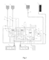
- FIG. 1 An exemplary implementation of a system for emission-free year-round generation, storage and processing of thermal and electrical energy according to the invention is shown schematically in Fig. 1 , wherein Fig. 1 shows a schematic diagram of the entire system for emission-free year-round generation, storage and processing of thermal and electrical energy.
- the system for emission-free year-round generation, storage and processing of thermal and electrical energy is built from two sets of rotating solar collectors 1 and 2, from photovoltaic panel modules installed on rotating tracers 3, from stationary photovoltaic panel modules 4.
- the set of rotary solar collectors 1 is connected via a three-way valve 13 and a five circulation pump 12 to the upper and lower coils of the hot water buffer tank 5 and to the lower heat exchanger 38 installed inside the insulated underground tank 9.
- the upper and lower coils of the hot water buffer tank 5, through the three-way valve 14, are connected to the upper heat exchanger 37 mounted inside the insulated underground tank 9 through the three circulation pump 32 and the three-way valves 30, 31, 33, and 34.
- a three-way valve 14 is installed between the upper and lower coils of the hot water buffer tank 5.
- the set of rotary solar collectors 2 is connected to the lower coil of the hot water buffer tank 6 and to the lower heat exchanger 38 mounted inside the insulated underground tank 9 through a sixth circulation pump 15 and through a three-way valve 16.
- the hot water buffer tanks 5 and 6 are connected to each other via the none circulation pump 22.
- the upper coil of the hot water buffer cylinder 6 is connected to the hot water cylinder via the ten circulation pump 23 is connected to the hot water storage tank 7.
- Photovoltaic panel modules installed on rotating tracers 3 and stationary photovoltaic panel modules 4 are connected via seventh circulating pump 20 and eighth circulating pump 21 to a lower heat exchanger 40 mounted inside the uninsulated underground tank 10.
- the stationary photovoltaic panel modules 4 are connected via a eighth circulating pump 21 to a lower heat exchanger 40 mounted inside the uninsulated underground tank 10.
- the heat pump 8 on the lower heat source side is connected to an upper heat exchanger 37 installed inside the insulated underground tank 9 and to an upper heat exchanger 39 installed inside the uninsulated underground tank 10, wherein on the upper heat source side the heat pump 8 is connected to a lower heat exchanger 40 inside the insulated underground tank 9 and to a lower heat exchanger 40 installed inside the uninsulated underground tank 10 via a two circulation pump 19 and a three-way valve 18 and a plate heat exchanger 24.
- the heat pump 8 is also connected via a first circulation pump 26 and a three-way valve 28 to the ground heat exchanger 11, which is a vertical borehole in the ground.
- the heat pump 8 is connected to the plate heat exchanger 25 via a three circulation pump 32 and via three-way valves 27, 31, 33, 34, 35 and 36, while the plate heat exchanger 25 is connected to the hot water buffer tank 5 via a fourth circulation pump 29.
- heat pump 8 is connected via two circulation pump 19 and three-way valves 17 and 18 to hot water buffer cylinders 5 and 6.
Landscapes
- Engineering & Computer Science (AREA)
- Physics & Mathematics (AREA)
- Thermal Sciences (AREA)
- Chemical & Material Sciences (AREA)
- Combustion & Propulsion (AREA)
- Mechanical Engineering (AREA)
- General Engineering & Computer Science (AREA)
- Life Sciences & Earth Sciences (AREA)
- Sustainable Development (AREA)
- Sustainable Energy (AREA)
- Heat-Pump Type And Storage Water Heaters (AREA)
- Photovoltaic Devices (AREA)
Claims (9)
- Ein System zur ganzjährigen emissionsfreien Erzeugung, Speicherung und Verarbeitung von thermischer und elektrischer Energie, aufgebaut aus Gruppen von rotierenden Sonnenkollektoren, aus stationären Photovoltaikmodulen, aus Warmwasserpufferspeichern, aus einem Warmwasserspeicher, aus einem unterirdischen Wärmeenergiespeicher, aus einer Wärmepumpe, aus Systemumwälzpumpen, Dreiwegeventilen des Systems, Systemwärmetauschern, wobei die Wärmepumpe (8) direkt mit drei unteren Wärmequellen zusammenarbeitet, nämlich mit einem isolierten unterirdischen Speicher (9), mit einem nicht isolierten unterirdischen Speicher (10) und über eine erste Umwälzpumpe (26) und ein erstes Dreiwegeventil (28) mit einem Erdwärmetauscher (11), wobei die Wärmepumpe (8) auf der Seite einer unteren Wärmequelle mit einem oberen Wärmetauscher (37), der in dem isolierten unterirdischen Speicher (9) installiert ist, und mit einem oberen Wärmetauscher (39), der in dem nicht isolierten unterirdischen Speicher (10) installiert ist, verbunden ist, dadurch gekennzeichnet, dass das System Photovoltaikmodule umfasst, die auf rotierenden Tracern (3) installiert sind, das System Akkumulatoren für elektrische Energie zusammen mit Wechselrichtern umfasst, wobei die Wärmepumpe (8) auf der Seite einer oberen Wärmequelle über eine zweite Umwälzpumpe (19) und ein zweites Dreiwegeventil (18) und einen ersten Plattenwärmetauscher (24) mit einem unteren Wärmetauscher (4 0) verbunden ist, der in dem nicht isolierten unterirdischen Speicher (10) installiert ist, wobei die Wärmepumpe (8) über eine dritte Umwälzpumpe (32) und dritte Dreiwegeventile (27, 30, 31, 33, 34, 35, 36) auch mit einem zweiten Plattenwärmetauscher (25) verbunden ist, während der zweite Plattenwärmetauscher (25) über eine vierte Umwälzpumpe (29) mit einem ersten Warmwasserpufferspeicher (5) verbunden ist, und auf der Seite der oberen Wärmequelle die Wärmepumpe (8) über die zweite Umwälzpumpe (19), das zweite Dreiwegeventil (18) und ein viertes Dreiwegeventil (17) mit dem ersten Warmwasserpufferspeicher (5) und einem zweiten Warmwasserpufferspeicher (6) angeschlossen ist, wobei das System mindestens zwei Sätze von rotierenden Sonnenkollektoren (1, 2), die auf rotierenden Tracern (3) installierte Photovoltaikmodule und die stationären Photovoltaikmodule (4) umfasst, wobei ein erster Satz rotierender Sonnenkollektoren (1) über ein fünftes Dreiwegeventil (13) und eine fünfte Umwälzpumpe (12) mit den oberen und unteren Rohrschlangen des ersten Warmwasserpufferspeichers (5) für Warmwasser und mit einem unteren Wärmetauscher (38) verbunden ist, der im Inneren des isolierten unterirdischen Speichers (9) installiert ist, und die oberen und unteren Rohrschlangen des ersten Warmwasserpufferspeichers (5) über ein sechstes Dreiwegeventil (14) mit dem oberen Wärmetauscher (37) verbunden sind, der im Inneren des isolierten unterirdischen Speichers (9) installiert ist, und zwar mittels der dritten Umwälzpumpe (32) und der dritten Dreiwegeventile (30, 31, 33, 34), wobei das sechste Dreiwegeventil (14) zwischen der oberen und der unteren Rohrschlange des ersten Warmwasserpufferspeichers (5) installiert ist, während ein zweiter Satz rotierender Sonnenkollektoren (2) über eine sechste Umwälzpumpe (15) und ein siebtes Dreiwegeventil (16) mit einer unteren Rohrschlange des zweiten Warmwasserpufferspeichers (6) und mit dem unteren Wärmetauscher (3 8) verbunden ist, der in dem isolierten unterirdischen Speicher (9) montiert ist, und die stationären Photovoltaikmodule (4) über eine siebte Umwälzpumpe (20) und eine achte Umwälzpumpe (21) mit dem unteren Wärmetauscher (40), der im Inneren des nicht isolierten unterirdischen Speichers (10) montiert ist, verbunden sind, wobei die stationären Photovoltaikmodule (4) über die achte Umwälzpumpe (21) mit dem unteren Wärmetauscher (40) verbunden sind, der im Inneren des nicht isolierten unterirdischen Speichers (10) montiert ist.
- System nach Anspruch 1, wobei die Warmwasserpufferspeicher (5, 6) über eine neunte Umwälzpumpe (22) miteinander verbunden sind.
- System nach Anspruch 1, wobei die obere Rohrschlange des zweiten Warmwasserpufferspeichers (6) über eine zehnte Umwälzpumpe (23) mit einem Warmwasserspeicher (7) verbunden ist.
- System nach Anspruch 1, wobei der Erdwärmetauscher (11) ein vertikales Bohrloch im Boden um den nicht isolierten unterirdischen Speicher (10) ist.
- System nach Anspruch 1, wobei das System so eingerichtet ist, dass die mit dem isolierten unterirdischen Speicher (9) verbundene Wärmepumpe (8) bei Wärmebedarf über die dritte Umwälzpumpe (32) und eine geeignete Konfiguration der dritten Dreiwegeventile (31, 33, 34, 35) Wärme entzieht.
- System nach Anspruch 1, wobei das System so eingerichtet ist, dass die Wärmepumpe (8) im Falle einer Erschöpfung der Wärmeenergie im isolierten unterirdischen Speicher (9) Wärmeenergie aus dem nicht isolierten unterirdischen Speicher (10) nutzt, um als ihre untere Wärmequelle zu arbeiten, wobei die dritte Umwälzpumpe (32) und eine geeignete Konfiguration der dritten Dreiwegeventile (31, 33, 34, 35, 36) verwendet werden, um Wärme aus dem nicht isolierten unterirdischen Speicher (10) zu erhalten.
- System nach Anspruch 1, wobei das System so eingerichtet ist, dass der erste Warmwasserpufferspeicher (5) bei einem Kühlungserzeugungsprozess als Kältespeicher verwendet wird.
- System nach Anspruch 7, wobei das System so eingerichtet ist, dass die Wärmepumpe (8) bei dem Kühlungserzeugungsprozess die dritte Umwälzpumpe (32) und eine geeignete Konfiguration der dritten Dreiwegeventile (27, 31, 33, 34, 35, 36) verwendet, um die Kühlenergie zum zweiten Plattenwärmetauscher (25) zu pumpen, von dem die Kühlenergie über die vierte Umwälzpumpe (29) zum Kältespeicher (5) transportiert wird, wobei die bei der Kälteerzeugung erzeugte Wärme von der Wärmepumpe (8) über die zweite Umwälzpumpe (19) und die entsprechende Konfiguration des zweiten Dreiwegeventils (18) zum ersten Plattenwärmetauscher (24) transportiert wird, wo die vom ersten Plattenwärmetauscher (24) gesammelte Wärmeenergie von der ersten Umwälzpumpe (26) zum Erdwärmetauscher (11) transportiert wird, wo sie regeneriert wird.
- System nach Anspruch 8, wobei das System so eingerichtet ist, dass die im ersten Plattenwärmetauscher (24) aufgenommene Wärmeenergie über die erste Umwälzpumpe (26) und über eine geeignete Konfiguration des ersten Dreiwegeventils (28) gleichzeitig zum Erdwärmetauscher (11) und zum nicht isolierten unterirdischem Speicher (10) transportiert wird.
Applications Claiming Priority (2)
| Application Number | Priority Date | Filing Date | Title |
|---|---|---|---|
| PL434913A PL242631B1 (pl) | 2020-08-06 | 2020-08-06 | System do bezemisyjnego całorocznego wytwarzania, magazynowania i przetwarzania energii cieplnej i elektrycznej |
| PCT/PL2021/000038 WO2022031179A1 (en) | 2020-08-06 | 2021-06-24 | System for emission-free year-round generation, storage and processing of thermal and electrical energy |
Publications (3)
| Publication Number | Publication Date |
|---|---|
| EP4193094A1 EP4193094A1 (de) | 2023-06-14 |
| EP4193094B1 true EP4193094B1 (de) | 2024-11-20 |
| EP4193094C0 EP4193094C0 (de) | 2024-11-20 |
Family
ID=76943072
Family Applications (1)
| Application Number | Title | Priority Date | Filing Date |
|---|---|---|---|
| EP21742545.3A Active EP4193094B1 (de) | 2020-08-06 | 2021-06-24 | System zur emissionsfreien ganzjährigen erzeugung, speicherung und verarbeitung von thermischer und elektrischer energie |
Country Status (3)
| Country | Link |
|---|---|
| EP (1) | EP4193094B1 (de) |
| PL (1) | PL242631B1 (de) |
| WO (1) | WO2022031179A1 (de) |
Citations (1)
| Publication number | Priority date | Publication date | Assignee | Title |
|---|---|---|---|---|
| EP0382456B1 (de) * | 1989-02-07 | 1996-06-26 | Envirotech Investments Limited | Gebäude |
Family Cites Families (9)
| Publication number | Priority date | Publication date | Assignee | Title |
|---|---|---|---|---|
| PL207849A3 (de) | 1978-06-21 | 1980-09-22 | Politechnika Slaska Im Wincent | |
| DE3004062A1 (de) * | 1980-02-05 | 1981-08-13 | Franz Karl 8500 Nürnberg Krieb | Ganzjaehrige heizung |
| WO2007109899A1 (en) * | 2006-03-28 | 2007-10-04 | Menova Energy Inc. | Energy supply system |
| US7441558B2 (en) | 2006-10-19 | 2008-10-28 | Elcal Research, L.L.C. | Active thermal energy storage system |
| DE102007019748A1 (de) * | 2007-04-20 | 2008-10-23 | Kai Kowalewski | Wärmeerzeugung über Solarenergie in Verbindung mit Geothermie zur ganzjährigen Nutzung |
| US8667806B2 (en) | 2009-09-21 | 2014-03-11 | Airgenerate, Llc | Efficient photovoltaic (PV) cell based heat pump liquid heater |
| JP5205353B2 (ja) | 2009-09-24 | 2013-06-05 | 株式会社日立製作所 | ヒートポンプ発電システム |
| PL222460B1 (pl) | 2013-11-04 | 2016-07-29 | Zielona Energia Spółka Z Ograniczoną Odpowiedzialnością | Zintegrowany system zasilania budynków energią elektryczną i cieplną z zastosowaniem odnawialnych źródeł energii |
| EP3012539B1 (de) * | 2014-10-21 | 2017-09-06 | LVI-Energiakeskus Aro Oy | Steuerung eines Heizsystems |
-
2020
- 2020-08-06 PL PL434913A patent/PL242631B1/pl unknown
-
2021
- 2021-06-24 EP EP21742545.3A patent/EP4193094B1/de active Active
- 2021-06-24 WO PCT/PL2021/000038 patent/WO2022031179A1/en not_active Ceased
Patent Citations (1)
| Publication number | Priority date | Publication date | Assignee | Title |
|---|---|---|---|---|
| EP0382456B1 (de) * | 1989-02-07 | 1996-06-26 | Envirotech Investments Limited | Gebäude |
Also Published As
| Publication number | Publication date |
|---|---|
| WO2022031179A1 (en) | 2022-02-10 |
| PL242631B1 (pl) | 2023-03-27 |
| EP4193094C0 (de) | 2024-11-20 |
| PL434913A1 (pl) | 2022-02-07 |
| EP4193094A1 (de) | 2023-06-14 |
Similar Documents
| Publication | Publication Date | Title |
|---|---|---|
| RU2350847C1 (ru) | Система автономного теплоснабжения потребителей с использованием низкопотенциального источника тепла и электроснабжения от возобновляемых источников энергии | |
| US6372978B1 (en) | Wind/sun solar collection system (HS2) | |
| EP2914918B1 (de) | Wärmeenergiespeichersystem mit einer kombinierten heiz- und kältemaschine und verfahren zur verwendung des wärmeenergiespeichersystems | |
| CN206669847U (zh) | 热电厂区域多能互补能源微网系统 | |
| CN115468207B (zh) | 利用光伏发电与沙土高温储热的建筑梯级供热系统和方法 | |
| Kakaza et al. | Effect of solar water heating system in reducing household energy consumption | |
| CN116557944A (zh) | 一种地热耦合光伏光热跨季节储能系统 | |
| CN102809245A (zh) | 完全太阳能全天候冷热电气联产联供系统 | |
| CN114001493A (zh) | 一种基于可再生能源耦合应用的零碳冷热供应系统及方法 | |
| CN108224537A (zh) | 风光互补型智能供热供电系统 | |
| CN216522492U (zh) | 一种基于可再生能源耦合应用的零碳冷热供应系统 | |
| EP4193094B1 (de) | System zur emissionsfreien ganzjährigen erzeugung, speicherung und verarbeitung von thermischer und elektrischer energie | |
| CN207247335U (zh) | 一种农村分布式风电供暖系统 | |
| RU2636018C2 (ru) | Система отопления и горячего водоснабжения помещений | |
| RU185808U1 (ru) | Тепличный комплекс с системой комбинированного теплоснабжения | |
| CN205878678U (zh) | 太阳能风能空气能采暖制冷及热水系统 | |
| CN107575928A (zh) | 一种农村分布式风电供暖系统及方法 | |
| CN102901161B (zh) | 一种太阳能地温空调 | |
| EP4619686A1 (de) | Bodenspeicherung mit verbesserter niedrigtemperatursensibler wärme und heiz-/kühlsystem | |
| RU35386U1 (ru) | Система автономного энергоснабжения жилых и производственных помещений | |
| CN109405045A (zh) | 一种农业设施自供暖系统及方法 | |
| PL222460B1 (pl) | Zintegrowany system zasilania budynków energią elektryczną i cieplną z zastosowaniem odnawialnych źródeł energii | |
| CN113719881A (zh) | 户式零碳热源供热集成系统 | |
| CN219141590U (zh) | 一种可再生能源储能装置 | |
| CN112197333A (zh) | 基于光伏发电余热的地源热泵供暖系统 |
Legal Events
| Date | Code | Title | Description |
|---|---|---|---|
| STAA | Information on the status of an ep patent application or granted ep patent |
Free format text: STATUS: UNKNOWN |
|
| STAA | Information on the status of an ep patent application or granted ep patent |
Free format text: STATUS: THE INTERNATIONAL PUBLICATION HAS BEEN MADE |
|
| PUAI | Public reference made under article 153(3) epc to a published international application that has entered the european phase |
Free format text: ORIGINAL CODE: 0009012 |
|
| STAA | Information on the status of an ep patent application or granted ep patent |
Free format text: STATUS: REQUEST FOR EXAMINATION WAS MADE |
|
| 17P | Request for examination filed |
Effective date: 20221206 |
|
| AK | Designated contracting states |
Kind code of ref document: A1 Designated state(s): AL AT BE BG CH CY CZ DE DK EE ES FI FR GB GR HR HU IE IS IT LI LT LU LV MC MK MT NL NO PL PT RO RS SE SI SK SM TR |
|
| DAV | Request for validation of the european patent (deleted) | ||
| DAX | Request for extension of the european patent (deleted) | ||
| GRAP | Despatch of communication of intention to grant a patent |
Free format text: ORIGINAL CODE: EPIDOSNIGR1 |
|
| STAA | Information on the status of an ep patent application or granted ep patent |
Free format text: STATUS: GRANT OF PATENT IS INTENDED |
|
| INTG | Intention to grant announced |
Effective date: 20240617 |
|
| GRAS | Grant fee paid |
Free format text: ORIGINAL CODE: EPIDOSNIGR3 |
|
| GRAA | (expected) grant |
Free format text: ORIGINAL CODE: 0009210 |
|
| STAA | Information on the status of an ep patent application or granted ep patent |
Free format text: STATUS: THE PATENT HAS BEEN GRANTED |
|
| AK | Designated contracting states |
Kind code of ref document: B1 Designated state(s): AL AT BE BG CH CY CZ DE DK EE ES FI FR GB GR HR HU IE IS IT LI LT LU LV MC MK MT NL NO PL PT RO RS SE SI SK SM TR |
|
| REG | Reference to a national code |
Ref country code: GB Ref legal event code: FG4D |
|
| REG | Reference to a national code |
Ref country code: CH Ref legal event code: EP |
|
| REG | Reference to a national code |
Ref country code: DE Ref legal event code: R096 Ref document number: 602021022117 Country of ref document: DE |
|
| REG | Reference to a national code |
Ref country code: IE Ref legal event code: FG4D |
|
| U01 | Request for unitary effect filed |
Effective date: 20241220 |
|
| U07 | Unitary effect registered |
Designated state(s): AT BE BG DE DK EE FI FR IT LT LU LV MT NL PT RO SE SI Effective date: 20250110 |
|
| PG25 | Lapsed in a contracting state [announced via postgrant information from national office to epo] |
Ref country code: IS Free format text: LAPSE BECAUSE OF FAILURE TO SUBMIT A TRANSLATION OF THE DESCRIPTION OR TO PAY THE FEE WITHIN THE PRESCRIBED TIME-LIMIT Effective date: 20250320 Ref country code: HR Free format text: LAPSE BECAUSE OF FAILURE TO SUBMIT A TRANSLATION OF THE DESCRIPTION OR TO PAY THE FEE WITHIN THE PRESCRIBED TIME-LIMIT Effective date: 20241120 |
|
| PG25 | Lapsed in a contracting state [announced via postgrant information from national office to epo] |
Ref country code: ES Free format text: LAPSE BECAUSE OF FAILURE TO SUBMIT A TRANSLATION OF THE DESCRIPTION OR TO PAY THE FEE WITHIN THE PRESCRIBED TIME-LIMIT Effective date: 20241120 |
|
| PG25 | Lapsed in a contracting state [announced via postgrant information from national office to epo] |
Ref country code: NO Free format text: LAPSE BECAUSE OF FAILURE TO SUBMIT A TRANSLATION OF THE DESCRIPTION OR TO PAY THE FEE WITHIN THE PRESCRIBED TIME-LIMIT Effective date: 20250220 |
|
| PG25 | Lapsed in a contracting state [announced via postgrant information from national office to epo] |
Ref country code: GR Free format text: LAPSE BECAUSE OF FAILURE TO SUBMIT A TRANSLATION OF THE DESCRIPTION OR TO PAY THE FEE WITHIN THE PRESCRIBED TIME-LIMIT Effective date: 20250221 |
|
| PG25 | Lapsed in a contracting state [announced via postgrant information from national office to epo] |
Ref country code: PL Free format text: LAPSE BECAUSE OF FAILURE TO SUBMIT A TRANSLATION OF THE DESCRIPTION OR TO PAY THE FEE WITHIN THE PRESCRIBED TIME-LIMIT Effective date: 20241120 |
|
| PG25 | Lapsed in a contracting state [announced via postgrant information from national office to epo] |
Ref country code: RS Free format text: LAPSE BECAUSE OF FAILURE TO SUBMIT A TRANSLATION OF THE DESCRIPTION OR TO PAY THE FEE WITHIN THE PRESCRIBED TIME-LIMIT Effective date: 20250220 |
|
| PG25 | Lapsed in a contracting state [announced via postgrant information from national office to epo] |
Ref country code: SM Free format text: LAPSE BECAUSE OF FAILURE TO SUBMIT A TRANSLATION OF THE DESCRIPTION OR TO PAY THE FEE WITHIN THE PRESCRIBED TIME-LIMIT Effective date: 20241120 |
|
| PG25 | Lapsed in a contracting state [announced via postgrant information from national office to epo] |
Ref country code: SK Free format text: LAPSE BECAUSE OF FAILURE TO SUBMIT A TRANSLATION OF THE DESCRIPTION OR TO PAY THE FEE WITHIN THE PRESCRIBED TIME-LIMIT Effective date: 20241120 |
|
| PG25 | Lapsed in a contracting state [announced via postgrant information from national office to epo] |
Ref country code: CZ Free format text: LAPSE BECAUSE OF FAILURE TO SUBMIT A TRANSLATION OF THE DESCRIPTION OR TO PAY THE FEE WITHIN THE PRESCRIBED TIME-LIMIT Effective date: 20241120 |
|
| U20 | Renewal fee for the european patent with unitary effect paid |
Year of fee payment: 5 Effective date: 20250625 |
|
| PLBE | No opposition filed within time limit |
Free format text: ORIGINAL CODE: 0009261 |
|
| STAA | Information on the status of an ep patent application or granted ep patent |
Free format text: STATUS: NO OPPOSITION FILED WITHIN TIME LIMIT |
|
| 26N | No opposition filed |
Effective date: 20250821 |
|
| REG | Reference to a national code |
Ref country code: CH Ref legal event code: H13 Free format text: ST27 STATUS EVENT CODE: U-0-0-H10-H13 (AS PROVIDED BY THE NATIONAL OFFICE) Effective date: 20260127 |
|
| PG25 | Lapsed in a contracting state [announced via postgrant information from national office to epo] |
Ref country code: MC Free format text: LAPSE BECAUSE OF FAILURE TO SUBMIT A TRANSLATION OF THE DESCRIPTION OR TO PAY THE FEE WITHIN THE PRESCRIBED TIME-LIMIT Effective date: 20241120 |
|
| GBPC | Gb: european patent ceased through non-payment of renewal fee |
Effective date: 20250624 |
|
| PG25 | Lapsed in a contracting state [announced via postgrant information from national office to epo] |
Ref country code: GB Free format text: LAPSE BECAUSE OF NON-PAYMENT OF DUE FEES Effective date: 20250624 |
|
| PG25 | Lapsed in a contracting state [announced via postgrant information from national office to epo] |
Ref country code: IE Free format text: LAPSE BECAUSE OF NON-PAYMENT OF DUE FEES Effective date: 20250624 |
|
| PG25 | Lapsed in a contracting state [announced via postgrant information from national office to epo] |
Ref country code: CH Free format text: LAPSE BECAUSE OF NON-PAYMENT OF DUE FEES Effective date: 20250630 |