EP4193090B1 - Griff für einen tragbaren zylinder - Google Patents
Griff für einen tragbaren zylinder Download PDFInfo
- Publication number
- EP4193090B1 EP4193090B1 EP21777599.8A EP21777599A EP4193090B1 EP 4193090 B1 EP4193090 B1 EP 4193090B1 EP 21777599 A EP21777599 A EP 21777599A EP 4193090 B1 EP4193090 B1 EP 4193090B1
- Authority
- EP
- European Patent Office
- Prior art keywords
- handle
- circumferentially spaced
- collar
- tabs
- ledges
- Prior art date
- Legal status (The legal status is an assumption and is not a legal conclusion. Google has not performed a legal analysis and makes no representation as to the accuracy of the status listed.)
- Active
Links
Images







Classifications
-
- F—MECHANICAL ENGINEERING; LIGHTING; HEATING; WEAPONS; BLASTING
- F17—STORING OR DISTRIBUTING GASES OR LIQUIDS
- F17C—VESSELS FOR CONTAINING OR STORING COMPRESSED, LIQUEFIED OR SOLIDIFIED GASES; FIXED-CAPACITY GAS-HOLDERS; FILLING VESSELS WITH, OR DISCHARGING FROM VESSELS, COMPRESSED, LIQUEFIED, OR SOLIDIFIED GASES
- F17C13/00—Details of vessels or of the filling or discharging of vessels
- F17C13/08—Mounting arrangements for vessels
- F17C13/084—Mounting arrangements for vessels for small-sized storage vessels, e.g. compressed gas cylinders or bottles, disposable gas vessels, vessels adapted for automotive use
-
- F—MECHANICAL ENGINEERING; LIGHTING; HEATING; WEAPONS; BLASTING
- F17—STORING OR DISTRIBUTING GASES OR LIQUIDS
- F17C—VESSELS FOR CONTAINING OR STORING COMPRESSED, LIQUEFIED OR SOLIDIFIED GASES; FIXED-CAPACITY GAS-HOLDERS; FILLING VESSELS WITH, OR DISCHARGING FROM VESSELS, COMPRESSED, LIQUEFIED, OR SOLIDIFIED GASES
- F17C13/00—Details of vessels or of the filling or discharging of vessels
- F17C13/06—Closures, e.g. cap, breakable member
-
- F—MECHANICAL ENGINEERING; LIGHTING; HEATING; WEAPONS; BLASTING
- F17—STORING OR DISTRIBUTING GASES OR LIQUIDS
- F17C—VESSELS FOR CONTAINING OR STORING COMPRESSED, LIQUEFIED OR SOLIDIFIED GASES; FIXED-CAPACITY GAS-HOLDERS; FILLING VESSELS WITH, OR DISCHARGING FROM VESSELS, COMPRESSED, LIQUEFIED, OR SOLIDIFIED GASES
- F17C13/00—Details of vessels or of the filling or discharging of vessels
- F17C13/04—Arrangement or mounting of valves
-
- F—MECHANICAL ENGINEERING; LIGHTING; HEATING; WEAPONS; BLASTING
- F17—STORING OR DISTRIBUTING GASES OR LIQUIDS
- F17C—VESSELS FOR CONTAINING OR STORING COMPRESSED, LIQUEFIED OR SOLIDIFIED GASES; FIXED-CAPACITY GAS-HOLDERS; FILLING VESSELS WITH, OR DISCHARGING FROM VESSELS, COMPRESSED, LIQUEFIED, OR SOLIDIFIED GASES
- F17C2201/00—Vessel construction, in particular geometry, arrangement or size
- F17C2201/01—Shape
- F17C2201/0104—Shape cylindrical
- F17C2201/0109—Shape cylindrical with exteriorly curved end-piece
-
- F—MECHANICAL ENGINEERING; LIGHTING; HEATING; WEAPONS; BLASTING
- F17—STORING OR DISTRIBUTING GASES OR LIQUIDS
- F17C—VESSELS FOR CONTAINING OR STORING COMPRESSED, LIQUEFIED OR SOLIDIFIED GASES; FIXED-CAPACITY GAS-HOLDERS; FILLING VESSELS WITH, OR DISCHARGING FROM VESSELS, COMPRESSED, LIQUEFIED, OR SOLIDIFIED GASES
- F17C2201/00—Vessel construction, in particular geometry, arrangement or size
- F17C2201/03—Orientation
- F17C2201/032—Orientation with substantially vertical main axis
-
- F—MECHANICAL ENGINEERING; LIGHTING; HEATING; WEAPONS; BLASTING
- F17—STORING OR DISTRIBUTING GASES OR LIQUIDS
- F17C—VESSELS FOR CONTAINING OR STORING COMPRESSED, LIQUEFIED OR SOLIDIFIED GASES; FIXED-CAPACITY GAS-HOLDERS; FILLING VESSELS WITH, OR DISCHARGING FROM VESSELS, COMPRESSED, LIQUEFIED, OR SOLIDIFIED GASES
- F17C2201/00—Vessel construction, in particular geometry, arrangement or size
- F17C2201/05—Size
- F17C2201/056—Small (<1 m3)
-
- F—MECHANICAL ENGINEERING; LIGHTING; HEATING; WEAPONS; BLASTING
- F17—STORING OR DISTRIBUTING GASES OR LIQUIDS
- F17C—VESSELS FOR CONTAINING OR STORING COMPRESSED, LIQUEFIED OR SOLIDIFIED GASES; FIXED-CAPACITY GAS-HOLDERS; FILLING VESSELS WITH, OR DISCHARGING FROM VESSELS, COMPRESSED, LIQUEFIED, OR SOLIDIFIED GASES
- F17C2201/00—Vessel construction, in particular geometry, arrangement or size
- F17C2201/05—Size
- F17C2201/058—Size portable (<30 l)
-
- F—MECHANICAL ENGINEERING; LIGHTING; HEATING; WEAPONS; BLASTING
- F17—STORING OR DISTRIBUTING GASES OR LIQUIDS
- F17C—VESSELS FOR CONTAINING OR STORING COMPRESSED, LIQUEFIED OR SOLIDIFIED GASES; FIXED-CAPACITY GAS-HOLDERS; FILLING VESSELS WITH, OR DISCHARGING FROM VESSELS, COMPRESSED, LIQUEFIED, OR SOLIDIFIED GASES
- F17C2203/00—Vessel construction, in particular walls or details thereof
- F17C2203/06—Materials for walls or layers thereof; Properties or structures of walls or their materials
- F17C2203/0634—Materials for walls or layers thereof
- F17C2203/0636—Metals
-
- F—MECHANICAL ENGINEERING; LIGHTING; HEATING; WEAPONS; BLASTING
- F17—STORING OR DISTRIBUTING GASES OR LIQUIDS
- F17C—VESSELS FOR CONTAINING OR STORING COMPRESSED, LIQUEFIED OR SOLIDIFIED GASES; FIXED-CAPACITY GAS-HOLDERS; FILLING VESSELS WITH, OR DISCHARGING FROM VESSELS, COMPRESSED, LIQUEFIED, OR SOLIDIFIED GASES
- F17C2203/00—Vessel construction, in particular walls or details thereof
- F17C2203/06—Materials for walls or layers thereof; Properties or structures of walls or their materials
- F17C2203/0634—Materials for walls or layers thereof
- F17C2203/0636—Metals
- F17C2203/0639—Steels
-
- F—MECHANICAL ENGINEERING; LIGHTING; HEATING; WEAPONS; BLASTING
- F17—STORING OR DISTRIBUTING GASES OR LIQUIDS
- F17C—VESSELS FOR CONTAINING OR STORING COMPRESSED, LIQUEFIED OR SOLIDIFIED GASES; FIXED-CAPACITY GAS-HOLDERS; FILLING VESSELS WITH, OR DISCHARGING FROM VESSELS, COMPRESSED, LIQUEFIED, OR SOLIDIFIED GASES
- F17C2203/00—Vessel construction, in particular walls or details thereof
- F17C2203/06—Materials for walls or layers thereof; Properties or structures of walls or their materials
- F17C2203/0634—Materials for walls or layers thereof
- F17C2203/0658—Synthetics
- F17C2203/066—Plastics
-
- F—MECHANICAL ENGINEERING; LIGHTING; HEATING; WEAPONS; BLASTING
- F17—STORING OR DISTRIBUTING GASES OR LIQUIDS
- F17C—VESSELS FOR CONTAINING OR STORING COMPRESSED, LIQUEFIED OR SOLIDIFIED GASES; FIXED-CAPACITY GAS-HOLDERS; FILLING VESSELS WITH, OR DISCHARGING FROM VESSELS, COMPRESSED, LIQUEFIED, OR SOLIDIFIED GASES
- F17C2205/00—Vessel construction, in particular mounting arrangements, attachments or identifications means
- F17C2205/01—Mounting arrangements
- F17C2205/0153—Details of mounting arrangements
- F17C2205/0157—Details of mounting arrangements for transport
- F17C2205/0165—Details of mounting arrangements for transport with handgrip
-
- F—MECHANICAL ENGINEERING; LIGHTING; HEATING; WEAPONS; BLASTING
- F17—STORING OR DISTRIBUTING GASES OR LIQUIDS
- F17C—VESSELS FOR CONTAINING OR STORING COMPRESSED, LIQUEFIED OR SOLIDIFIED GASES; FIXED-CAPACITY GAS-HOLDERS; FILLING VESSELS WITH, OR DISCHARGING FROM VESSELS, COMPRESSED, LIQUEFIED, OR SOLIDIFIED GASES
- F17C2205/00—Vessel construction, in particular mounting arrangements, attachments or identifications means
- F17C2205/03—Fluid connections, filters, valves, closure means or other attachments
- F17C2205/0302—Fittings, valves, filters, or components in connection with the gas storage device
- F17C2205/0308—Protective caps
-
- F—MECHANICAL ENGINEERING; LIGHTING; HEATING; WEAPONS; BLASTING
- F17—STORING OR DISTRIBUTING GASES OR LIQUIDS
- F17C—VESSELS FOR CONTAINING OR STORING COMPRESSED, LIQUEFIED OR SOLIDIFIED GASES; FIXED-CAPACITY GAS-HOLDERS; FILLING VESSELS WITH, OR DISCHARGING FROM VESSELS, COMPRESSED, LIQUEFIED, OR SOLIDIFIED GASES
- F17C2205/00—Vessel construction, in particular mounting arrangements, attachments or identifications means
- F17C2205/03—Fluid connections, filters, valves, closure means or other attachments
- F17C2205/0302—Fittings, valves, filters, or components in connection with the gas storage device
- F17C2205/0323—Valves
-
- F—MECHANICAL ENGINEERING; LIGHTING; HEATING; WEAPONS; BLASTING
- F17—STORING OR DISTRIBUTING GASES OR LIQUIDS
- F17C—VESSELS FOR CONTAINING OR STORING COMPRESSED, LIQUEFIED OR SOLIDIFIED GASES; FIXED-CAPACITY GAS-HOLDERS; FILLING VESSELS WITH, OR DISCHARGING FROM VESSELS, COMPRESSED, LIQUEFIED, OR SOLIDIFIED GASES
- F17C2221/00—Handled fluid, in particular type of fluid
- F17C2221/03—Mixtures
- F17C2221/032—Hydrocarbons
- F17C2221/035—Propane butane, e.g. LPG, GPL
-
- F—MECHANICAL ENGINEERING; LIGHTING; HEATING; WEAPONS; BLASTING
- F17—STORING OR DISTRIBUTING GASES OR LIQUIDS
- F17C—VESSELS FOR CONTAINING OR STORING COMPRESSED, LIQUEFIED OR SOLIDIFIED GASES; FIXED-CAPACITY GAS-HOLDERS; FILLING VESSELS WITH, OR DISCHARGING FROM VESSELS, COMPRESSED, LIQUEFIED, OR SOLIDIFIED GASES
- F17C2223/00—Handled fluid before transfer, i.e. state of fluid when stored in the vessel or before transfer from the vessel
- F17C2223/01—Handled fluid before transfer, i.e. state of fluid when stored in the vessel or before transfer from the vessel characterised by the phase
- F17C2223/0107—Single phase
- F17C2223/0123—Single phase gaseous, e.g. CNG, GNC
-
- F—MECHANICAL ENGINEERING; LIGHTING; HEATING; WEAPONS; BLASTING
- F17—STORING OR DISTRIBUTING GASES OR LIQUIDS
- F17C—VESSELS FOR CONTAINING OR STORING COMPRESSED, LIQUEFIED OR SOLIDIFIED GASES; FIXED-CAPACITY GAS-HOLDERS; FILLING VESSELS WITH, OR DISCHARGING FROM VESSELS, COMPRESSED, LIQUEFIED, OR SOLIDIFIED GASES
- F17C2223/00—Handled fluid before transfer, i.e. state of fluid when stored in the vessel or before transfer from the vessel
- F17C2223/01—Handled fluid before transfer, i.e. state of fluid when stored in the vessel or before transfer from the vessel characterised by the phase
- F17C2223/0146—Two-phase
- F17C2223/0153—Liquefied gas, e.g. LPG, GPL
-
- F—MECHANICAL ENGINEERING; LIGHTING; HEATING; WEAPONS; BLASTING
- F17—STORING OR DISTRIBUTING GASES OR LIQUIDS
- F17C—VESSELS FOR CONTAINING OR STORING COMPRESSED, LIQUEFIED OR SOLIDIFIED GASES; FIXED-CAPACITY GAS-HOLDERS; FILLING VESSELS WITH, OR DISCHARGING FROM VESSELS, COMPRESSED, LIQUEFIED, OR SOLIDIFIED GASES
- F17C2223/00—Handled fluid before transfer, i.e. state of fluid when stored in the vessel or before transfer from the vessel
- F17C2223/03—Handled fluid before transfer, i.e. state of fluid when stored in the vessel or before transfer from the vessel characterised by the pressure level
- F17C2223/033—Small pressure, e.g. for liquefied gas
-
- F—MECHANICAL ENGINEERING; LIGHTING; HEATING; WEAPONS; BLASTING
- F17—STORING OR DISTRIBUTING GASES OR LIQUIDS
- F17C—VESSELS FOR CONTAINING OR STORING COMPRESSED, LIQUEFIED OR SOLIDIFIED GASES; FIXED-CAPACITY GAS-HOLDERS; FILLING VESSELS WITH, OR DISCHARGING FROM VESSELS, COMPRESSED, LIQUEFIED, OR SOLIDIFIED GASES
- F17C2223/00—Handled fluid before transfer, i.e. state of fluid when stored in the vessel or before transfer from the vessel
- F17C2223/03—Handled fluid before transfer, i.e. state of fluid when stored in the vessel or before transfer from the vessel characterised by the pressure level
- F17C2223/035—High pressure (>10 bar)
-
- F—MECHANICAL ENGINEERING; LIGHTING; HEATING; WEAPONS; BLASTING
- F17—STORING OR DISTRIBUTING GASES OR LIQUIDS
- F17C—VESSELS FOR CONTAINING OR STORING COMPRESSED, LIQUEFIED OR SOLIDIFIED GASES; FIXED-CAPACITY GAS-HOLDERS; FILLING VESSELS WITH, OR DISCHARGING FROM VESSELS, COMPRESSED, LIQUEFIED, OR SOLIDIFIED GASES
- F17C2270/00—Applications
- F17C2270/07—Applications for household use
- F17C2270/0709—Camping gas
-
- F—MECHANICAL ENGINEERING; LIGHTING; HEATING; WEAPONS; BLASTING
- F17—STORING OR DISTRIBUTING GASES OR LIQUIDS
- F17C—VESSELS FOR CONTAINING OR STORING COMPRESSED, LIQUEFIED OR SOLIDIFIED GASES; FIXED-CAPACITY GAS-HOLDERS; FILLING VESSELS WITH, OR DISCHARGING FROM VESSELS, COMPRESSED, LIQUEFIED, OR SOLIDIFIED GASES
- F17C2270/00—Applications
- F17C2270/07—Applications for household use
- F17C2270/0745—Gas bottles
Definitions
- the present invention relates to a portable cylinder, and in particular to a handle for a portable cylinder.
- pressurized gas cylinders have been used for storage and transportation of pressurized gas products for household and industrial.
- the cylinders may be used for the storage of gas for cooking appliances such as stoves or grills, for the storage of refrigerant, for the storage of helium, etc.
- Many of these cylinders have traditionally been fabricated of steel with a steel cylindrical body having a valve at the top for controlling the flow of gas from the cylinder, a footing at the bottom to provide stability for the cylinder upon a supporting surface, and a handle at the top to assist in transporting the cylinder and for protecting the valve.
- US9932148B2 discloses a portable pressurized gas cylinder with a handle according to the preamble of claim 1.
- a handle for a cylinder includes a shroud portion configured to attach to a collar of the cylinder, the shroud portion including a plurality of circumferentially spaced ledges for abutting an underside of a respective one of a plurality of circumferentially spaced tabs of the collar, and at least one tab for engaging the collar, and a handle portion extending from the shroud portion and having one or more areas for grasping the handle.
- a portable cylinder in accordance with another embodiment of the present invention, includes a tank having an upper portion having a valve port, a mounting collar coupled to the upper portion of the tank, the mounting collar having an upwardly extending portion surrounding the valve port and a plurality of circumferentially spaced tabs extending radially outwardly from the upwardly extending portion, wherein a respective gap is formed between adjacent ones of the plurality of circumferentially spaced tabs, and a handle attached to the mounting collar.
- the handle includes a shroud portion including a plurality of circumferentially spaced ledges for abutting an underside of a respective one of the plurality of circumferentially spaced tabs, and at least one tab for engaging the mounting collar in one of the gaps, and a handle portion extending from the shroud portion and having one or more areas for grasping the handle.
- a method of assembling a portable cylinder including a tank having an upper portion, a collar attached to the tank at the upper portion, and a handle.
- the method includes lowering the handle onto the collar to cause a plurality of circumferentially spaced ledges of the handle to be received in gaps between adjacent ones of a plurality of circumferentially spaced tabs on the collar and to cause a deflectable tab of the handle to contact one of the plurality of circumferentially spaced tabs and to deflect, and rotating the handle until each of the plurality of circumferentially spaced ledges are positioned below a respective one of the plurality of circumferentially spaced tabs and the deflectable tab engages the collar in one of the gaps.
- Embodiments of the invention relate to methods and systems that relate to a portable cylinder.
- the cylinder has a tank having an upper portion having a valve port, a mounting collar coupled to the upper portion of the tank, and a handle attached to the mounting collar.
- the mounting collar has an upwardly extending portion surrounding the valve port and a plurality of circumferentially spaced tabs extending radially outwardly from the upwardly extending portion, wherein a respective gap is formed between adjacent ones of the plurality of circumferentially spaced tabs.
- the handle includes a shroud portion including a plurality of circumferentially spaced ledges for abutting an underside of a respective one of the plurality of circumferentially spaced tabs, and at least one tab for engaging the mounting collar in one of the gaps, and a handle portion extending from the shroud portion and having one or more areas for grasping the handle.
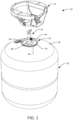
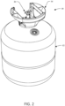
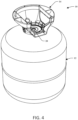
- the cylinder 10 includes a tank 12 configured to store a suitable pressurized fluid, a handle 14 attached to a top of the tank 12, and one or more feet 16 at a bottom of the tank 12.
- a suitable foot assembly may be attached to the bottom of the tank 12 in place of or in addition to the feet 16.
- the handle 14 and/or tank 12 can have a color that is chosen to reflect the different materials of the handle 14 and/or tank 12 and/or the different fluids stored in the tank 12.
- the tank 12 and/or handle 14 may be a first color to indicate that helium is stored in the tank 12, a second color to indicate that a first type of refrigerant is stored in the tank 12, a third color to indicate that a second type of refrigerant is stored in the tank 12, etc.
- the tank 12 may be made of a suitable material, such as a suitable metal, such as steel, and in an embodiment the tank may be non-refillable and thus disposable.
- the tank 12 includes an upper portion 18 having a valve port 20 for receiving a suitable valve 24, and a mounting collar 22 is provided surrounding the valve port 20.
- the mounting collar 22 may be secured to the upper portion 18 in any suitable manner, such as by a suitable welding process, such as spot welding, arc welding, etc., or may alternatively be integrally formed with the upper portion 18.
- the mounting collar 22 is positioned on the upper portion 18, the valve 24 is positioned in the valve port 20, and then the mounting collar 22 and the valve 24 are secured to the upper portion 18 at the same time in one welding process.
- the mounting collar 22 is positioned on the upper portion 18 and secured thereto in a first welding process, and the valve 24 is positioned in the valve port 20 and secured thereto in a second welding process.
- the mounting collar 22 may be made of a suitable material, such as metal, such as a steel of a grade to allow for welding, corrosion resistance, and to absorb tension on the cylinder without significant deformation.
- the mounting collar 22 has a base 26, which is shown as substantially circular, attached to the upper portion 18 and including an opening 28 surrounding the valve port 20, an upwardly extending portion 30 extending around a perimeter of the base 26, and a plurality of circumferentially spaced tabs 32 extending radially outwardly from the upwardly extending portion 30.
- a respective gap 34 is formed between adjacent ones of the plurality of circumferentially spaced tabs 32.
- the upwardly extending portion 30 may include an outwardly extending lip 36 at the areas between adjacent tabs 32.
- the mounting collar 22 includes seven circumferentially spaced tabs 32 equally spaced from one another, although it we be appreciated that any suitable number of tabs may be provided.
- the handle 14 includes a shroud portion 40 that attaches to the mounting collar 22 as will be described below in detail and a handle portion 42 projecting from the shroud portion 40.
- the handle 14 has the rigidity to maintain ergonomic integrity while having the flexibility to absorb energy, and may be made of a suitable material, such as a polymeric material that is compressible to absorb shocks during drops or impacts.
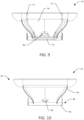
- the shroud portion 40 includes an inner body portion 50 with an opening 52 or through passage extending therethrough to surround the valve portion 20, an outer body portion 54 radially outwardly spaced from the inner body portion 50, and a base 56 extending therebetween.
- a channel 46 is defined between the inner and outer body portions 50 and 54 and the base 56 for receiving the mounting collar 22 such that a radially outer surface of the inner body portion 50 will abut or be in close proximity to the upwardly extending portion 30 and a radially inner surface of the outer body portion 54 will abut or be in close proximity to an outer edge of the circumferentially spaced tabs 32.
- the inner and outer body portions 50 and 54 may be circular or substantially circular to correspond to the geometry of the mounting collar 22.
- the shroud portion 40 also includes a plurality of circumferentially spaced ledges 58 extending radially inwardly from the outer body portion 54 in the channel 46.
- the shroud portion 40 includes seven ledges 58 equally spaced from one another, one ledge 58 corresponding to each of the plurality of circumferentially spaced tabs 32, although it will be appreciated that any suitable number of ledges 58 with suitable spacing may be provided.
- the ledges 58 are each spaced from the base 56 in a first direction to define areas for receiving a respective one of the plurality of circumferentially spaced tabs 32 of the mounting collar 22, and each ledge 58 is spaced from the inner body portion 50 in a respective second direction orthogonal the first direction to define an area for receiving the upwardly extending portion 30 of the mounting collar 22.
- Each ledge 58 can include a planar portion 60 and a plurality of circumferentially spaced ribs 62 below the planar portion 60 for providing support to the planar portion 60 while minimizing weight and material usage.
- a plurality of circumferentially spaced openings 64 are provided in the base 56 at a location where each opening 64 corresponds to one of the plurality of circumferentially spaced ledges 58. As illustrated, each opening 64 is larger than the respective ledge 58.
- the shroud portion 40 also includes at least one deflectable tab 66 extending radially outwardly from the inner body portion 50 in the channel 46. As shown, one deflectable tab 66 is provided between a pair of ledges 58 and corresponding openings 64 at a central portion of the handle 14. The deflectable tab 66 is configured to be deflected by one of the circumferentially spaced tabs 32 of the mounting collar 22 during installation, and includes a catch 68 that abuts the upwardly extending portion 30 within one of the gaps 34 once installed. An opening 48 is provide in the base 56 corresponding to the location of the deflectable tab 66.
- the handle portion 42 has a curved body 70 with first and second ends 72 and 74 circumferentially spaced from one another to define a gap through which a nozzle attached to the valve 24 extends.
- a support 76 is provided between the first and second ends 72 and 74 that has a substantially planar bottom and curved sides connecting to the first and second ends 72 and 74.
- a top of the curved body 70 is flat or substantially flat to serve as a foot if the tank 12 is positioned upside down as shown in FIGs. 7 and 8 , and to top of the curved body 70 has a circumference sized to keep the tank 12 stable when the tank is being supported on the curved body 70.
- the curved body 70 also includes a plurality of openings 78, 80, and 82 extending therethrough for material and weight savings and one or more openings 84 on a side of the body 70 for receiving a carrying device for transporting cylinders as described below.
- the body 70 and openings 78 and 80 define grip areas 86 near the top of the handle member 42 for a user or machine to grasp the handle member 42 to transport the cylinder 10.
- the opening 82 is sized to provide space for tools and/or filling devices that are accessing the valve 24.
- the one or more openings 84, and as shown an opening 84 at each side of the body 70 are formed through members 88 that are integral with one or more support ribs 90 or can be formed separate therefrom.
- the body 70 has inner and outer surfaces 94 and 96 at the top thereof that define a channel 98 for material and weight savings, and one or more support ribs 100 can be provided between the inner and outer surfaces 94 and 96.
- the inner surface 94 is shown with substantially straight portions to allow existing cartons to be utilized when transporting the handle 14.
- the handle 14 can also include a plurality of the support ribs 90 extending around an interior between the body 70 and the shroud portion 40 and a plurality of support ribs 92 extending around an exterior of the body 70.
- the support ribs 90 and 92 can be provided for structural integrity of the handle 14 while minimizing material usage. Any suitable number of support ribs may be provided along the interior and exterior of the body 70.
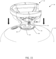
- FIGs. 15-22 show the attachment of the handle 14 to the tank 12 with portions cutaway and/or portions enlarged to illustrate the attachment of the handle 14 to the tank 12.
- the handle 14 may be attached to the tank 12 in any suitable manner, for example by a semi-autonomous process or by a fully autonomous process.
- the handle 14 and tank 12 are designed to be disposable, and as such the handle 14 is attached to the tank 12 in a substantially permanent manner and is removable upon destruction of one of the handle 14 or tank 12.
- the handle 14 is lowered onto the mounting collar in a downward direction. If not already aligned, the handle 14 can be rotated to align the plurality of circumferentially spaced ledges 58 with the respective gaps 34. As the handle 14 is further lowered, at least one deflectable tab 66 contacts a top of one of the plurality of circumferentially spaced tabs 32 and the plurality of circumferentially spaced ledges 58 are received in the gaps 34 as shown in FIG. 17 .
- the outer surface of the inner body portion 50 and base 56 of the shroud portion 40 contact the top of the upwardly extending portion 30 at the lip 36 preventing further downward movement of the handle 14.
- the plurality of circumferentially spaced ledges 58 pass through the respective gaps 34 and move below the plurality of circumferentially spaced tabs 32.
- the at least one deflectable tab 66 is deflected upward by the one of the plurality of circumferentially spaced tabs 32 that the deflectable tab 66 contacted.
- the handle 14 is then rotated relative to the tank 12, for example by about twenty-five degrees.
- the at least one deflectable tab 66 moves relative to the one of the plurality of circumferentially spaced tabs 32 and remains in the deflected position while the plurality of circumferentially spaced ledges 58 move under a respective one of the plurality of circumferentially spaced tabs 32.
- the handle 14 is rotated until the at least one deflectable tab 66 has moved past the end of the one of the plurality of circumferentially spaced tabs 32 into the adjacent one of the gaps 34 and returns to its unbiased position as shown in FIGs. 20 and 21 .
- FIG. 21 also illustrates the interaction between the handle 14 and the mounting collar 22 at one of the areas without one of the circumferentially spaced ledges 58
- FIG. 22 illustrates the assembled cylinder.
- the positioning of the at least one deflectable tab 66 in one of the gaps 34 between a pair of the plurality of circumferentially spaced tabs 32 prevents or substantially prevents rotation of the handle 14 relative to the mounting collar 22.
- each cylinder having a tank 12, a handle 14 attached to the tank, feet 16, and a valve 24 attached to a valve port. Also provided is a carrying handle 110 coupled to each cylinder 10.
- the carrying handle 110 may be made of a suitable material, such a metal, and may be formed by bending or otherwise altering a straight piece of metal.
- the carrying handle 110 include a grip portion 112 for a user or machine to grasp when transporting the cylinders 10, a pair of extension 114 extending downward from the grip portion 112, an attachment portion 116 extending outwardly from each of the extensions 114 substantially parallel thereto, and an upwardly angled portion 118 at the end of each attachment portion 116 to prevent the cylinders 10 from falling off the carrying handle 110 during transport.
- the extensions 114 space the attachment portions 116 from the grip portion 112 so the grip portion 112 can be grasped above the handles 14.
- each upwardly angled portion 118 and attachment portion 116 is received in one of the openings 84 in the handle 14 and advanced towards the respective valve 24 until the upwardly angled portion 118 passes through the respective opening 84 into an inner area of the respective handle 14.
- the grip portion 112 is then positioned above the handles 14 so the user can grasp the grip portion 112.
- the terms “may” and “may be” indicate a possibility of an occurrence within a set of circumstances; a possession of a specified property, characteristic or function; and/or qualify another verb by expressing one or more of an ability, capability, or possibility associated with the qualified verb. Accordingly, usage of “may” and “may be” indicates that a modified term is apparently appropriate, capable, or suitable for an indicated capacity, function, or usage, while taking into account that in some circumstances the modified term may sometimes not be appropriate, capable, or suitable. For example, in some circumstances an event or capacity can be expected, while in other circumstances the event or capacity cannot occur - this distinction is captured by the terms “may” and “may be.”
Landscapes
- Engineering & Computer Science (AREA)
- Mechanical Engineering (AREA)
- General Engineering & Computer Science (AREA)
- Filling Or Discharging Of Gas Storage Vessels (AREA)
- Details Of Rigid Or Semi-Rigid Containers (AREA)
Claims (15)
- Griff (14) für einen Zylinder (10) mit:einem Kragenbereich (40), der dazu ausgestaltet ist, an einem Bund (22) des Zylinders (10) befestigt zu werden, wobei der Kragenbereich (40) aufweisteinen Handgriffbereich (42), der von dem Kragenbereich (40) ausgeht und ein oder mehrere Gebiete zum Ergreifen des Griffs (14) hat,dadurch gekennzeichnet, dass der Kragenbereich (40) einen inneren Körperteil (50) und einen äußeren Körperteil (54), der radial nach außen auf Abstand zu dem inneren Körperteil (50) liegt, und eine Basis (56) aufweist, die zwischen inneren und äußeren Körperteilen verläuft, wobei ein Kanal (46) zwischen den inneren und äußeren Körperteilen (50, 54) und der Basis (56) definiert ist, um den Bund (22) aufzunehmen; und wobei der Kragenbereich (40) eine Mehrzahl von einer Umfangsrichtung beabstandeten Vorsprüngen (58) zum Anliegen an einer Unterseite einer jeweiligen aus einer Mehrzahl von in Umfangsrichtung beabstandeten Laschen (32) des Bundes (22) und wenigstens eine biegbare Lasche (66) zum Eingriff mit dem Bund (22) aufweist, wobei die beabstandeten Vorsprünge (58) von dem äußeren Körperteil (54) radial nach innen vorstehen und die wenigstens eine biegbare Lasche (66) von dem inneren Körperteil radial nach außen ausgedehnt ist.
- Griff (14) nach Anspruch 1, wobei die Mehrzahl von in Umfangsrichtung beabstandeten Vorsprünge (58) so bemessen sind, dass sie während eines ersten Installationsschrittes zwischen in Umfangsrichtung auf Abstand befindlichen Laschen (32) an dem Bund (22) aufgenommen werden können und so ausgestaltet sind, dass sie gedreht werden können, um in einem zweiten Installationsschritt unter den Laschen (32) positioniert zu werden.
- Griff (14) nach einem der Ansprüche 1 oder 2, wobei die Mehrzahl von den in Umfangsrichtung beabstandeten Vorsprüngen (58) jeweils einen ebenen Bereich (60) und eine Mehrzahl von in Umfangsrichtung beabstandeten Rippen (62) unter dem jeweiligen ebenen Bereich (60) aufweisen.
- Griff (14) nach einem der Ansprüche 1 bis 3, wobei jeder Vorsprung (58) in einer ersten Richtung auf Abstand zu der Basis (56) ist, um eine jeweilige aus der Mehrzahl der in Umfangsrichtung beabstandeten Laschen (32) aufzunehmen, und jeder Vorsprung (58) von dem inneren Körperteil (50) in einer zweiten Richtung, die senkrecht zur ersten Richtung ist, beabstandet ist, um ein Gebiet zu definieren, um einen nach oben verlaufenden Bereich des Bundes (22) aufzunehmen.
- Griff (14) nach einem der Ansprüche 1 bis 4, wobei die Basis (56) eine Mehrzahl von in Umfangsrichtung beabstandeten Öffnungen (64) über jedem aus der Mehrzahl der in Umfangsrichtung beabstandeten Vorsprünge (58) aufweist.
- Griff (14) nach einem der Ansprüche 1 bis 5, wobei der Griffbereich (42) einen Körper (70) mit ersten und zweiten Enden (72, 74) aufweist, die in Umfangsrichtung auf Abstand zueinander liegen, um eine Lücke zu definieren, durch die eine Düse verläuft.
- Griff (14) nach Anspruch 6, wobei der Körper (70) wenigstens zwei Öffnungen (78, 80) aufweist, die mit dem Körper (70) Griffbereiche (86) definieren.
- Transportabler Zylinder (10) mit:einem Tank (12) mit einem oberen Bereich (18) mit einem Ventilanschluss (20),einem Befestigungsbund (22), der mit dem oberen Bereich (18) des Tanks (12) verbunden ist, wobei der Befestigungsbund (22) einen nach oben vorstehenden Bereich (30) hat, der den Ventilanschluss (20) umgibt, und eine Mehrzahl von in Umfangsrichtung beabstandeten Laschen (32) aufweist, die von dem nach oben vorstehenden Bereich (30) radial nach außen vorstehen, wobei jeweils eine Lücke zwischen benachbarten aus der Mehrzahl in Umfangsrichtung beabstandeten Laschen (32) gebildet ist; undeinem Griff (14) nach einem der Ansprüche 1-7, wobei der Griff (14) an dem Befestigungsbund (22) befestigt ist, wobei die Basis (56) den Bund (22) aufnimmt, die Mehrzahl von in Umfangsrichtung beabstandeten Vorsprüngen (58) jeweils an einer Unterseite einer jeweiligen aus der Mehrzahl von in Umfangsrichtung beabstandeten Laschen (32) des Bundes (22) anliegt, und wobei die wenigstens eine biegbare Lasche (66) mit dem Bund (22) eingreift.
- Transportabler Zylinder (10) nach Anspruch 8, wobei die Mehrzahl von in Umfangsrichtung beabstandeten Vorsprüngen (58) solche Abmessungen haben, um während eines ersten Installationsschrittes in einer jeweiligen der Lücken aufgenommen zu werden, und so ausgestaltet sind, in einem zweiten Installationsschritt gedreht zu werden, um unter den Laschen (32) positioniert zu werden.
- Transportabler Zylinder (10) nach einem der Ansprüche 8 oder 9, wobei die Mehrzahl von in Umfangsrichtung beabstandeten Vorsprüngen (58) jeweils einen ebenen Bereich (60) und eine Mehrzahl von in Umfangsrichtung beabstandeten Rippen (62) unter dem jeweiligen ebenen Bereich (60) aufweist.
- Transportabler Zylinder (10) nach einem der Ansprüche 8 bis 10, wobei jeder Vorsprung (58) in einer ersten Richtung auf Abstand zu der Basis (56) ist, um ein Gebiet zu definieren, um eine jeweilige aus der Mehrzahl von in Umfangsrichtung beabstandeten Laschen (32) aufzunehmen, und wobei jeder Vorsprung (58) in einer zweiten Richtung senkrecht zur ersten Richtung auf Abstand zu dem inneren Körperteil (50) ist, um ein Gebiet zu definieren, um den nach oben vorstehenden Bereich (30) des Bundes (22) aufzunehmen.
- Transportabler Zylinder (10) nach einem der Ansprüche 8 bis 11, wobei die Basis (56) eine Mehrzahl von in Umfangsrichtung beabstandeten Öffnungen (64) jeweils über der Mehrzahl von in Umfangsrichtung beabstandeten Vorsprüngen (58) aufweist.
- Transportabler Zylinder (10) nach einem der Ansprüche 8 bis 12, der weiter ein an dem Ventilanschluss (20) angebrachtes Ventil (24) aufweist.
- Transportabler Zylinder (10) nach einem der Ansprüche 8 bis 13, wobei der Befestigungsbund (22) eine Basis (26) aufweist, die mit dem oberen Bereich (18) des Tanks (12) verbunden ist, und wobei der nach oben vorstehende Bereich (30) um einen Umfang der Basis (26) herum verläuft.
- Transportabler Zylinder (10) nach einem der Ansprüche 8 bis 14, wobei der Griff (42) einen Körper (70) mit ersten und zweiten Enden (72, 74) aufweist, die in Umfangsrichtung auf Abstand zueinander sind, um eine Lücke zu definieren, durch die eine Düse verläuft.
Applications Claiming Priority (2)
| Application Number | Priority Date | Filing Date | Title |
|---|---|---|---|
| US16/986,353 US11585491B2 (en) | 2020-08-06 | 2020-08-06 | Handle for a portable cylinder |
| PCT/US2021/044438 WO2022031775A1 (en) | 2020-08-06 | 2021-08-04 | Handle for a portable cylinder |
Publications (2)
| Publication Number | Publication Date |
|---|---|
| EP4193090A1 EP4193090A1 (de) | 2023-06-14 |
| EP4193090B1 true EP4193090B1 (de) | 2024-07-17 |
Family
ID=77913360
Family Applications (1)
| Application Number | Title | Priority Date | Filing Date |
|---|---|---|---|
| EP21777599.8A Active EP4193090B1 (de) | 2020-08-06 | 2021-08-04 | Griff für einen tragbaren zylinder |
Country Status (6)
| Country | Link |
|---|---|
| US (2) | US11585491B2 (de) |
| EP (1) | EP4193090B1 (de) |
| CN (1) | CN115038905B (de) |
| GB (1) | GB2606956B (de) |
| PT (1) | PT4193090T (de) |
| WO (1) | WO2022031775A1 (de) |
Families Citing this family (8)
| Publication number | Priority date | Publication date | Assignee | Title |
|---|---|---|---|---|
| USD936781S1 (en) * | 2018-07-25 | 2021-11-23 | L'Air Liquide, Société Anonyme pour l'Etude et l'Exploitation des Procédés Georges Claude | Apparatus for gas distribution |
| US11415449B2 (en) * | 2020-04-15 | 2022-08-16 | Worthington Cylinders Corporation | Cylinder attachment |
| US11585491B2 (en) * | 2020-08-06 | 2023-02-21 | Amtrol Licensing Inc. | Handle for a portable cylinder |
| US11512814B2 (en) * | 2020-09-25 | 2022-11-29 | Richard Bradley TAVES | Gas cylinder mobility aid |
| USD1055218S1 (en) | 2023-01-31 | 2024-12-24 | 3M Innovative Properties Company | Adhesive spray nozzle |
| US12129970B2 (en) * | 2023-02-17 | 2024-10-29 | Amtrol Licensing Inc. | Handle for a portable cylinder |
| USD1121536S1 (en) | 2023-06-12 | 2026-04-07 | Ghotra Innovations Inc. | Portable power station |
| USD1098358S1 (en) * | 2023-06-12 | 2025-10-14 | Ghotra Innovations Inc. | Hydrogen gas cylinder assembly |
Family Cites Families (12)
| Publication number | Priority date | Publication date | Assignee | Title |
|---|---|---|---|---|
| US4880134A (en) * | 1988-07-01 | 1989-11-14 | Wood Jr Theodore N | Protective cap assembly |
| FR2738897B1 (fr) * | 1995-09-19 | 1997-12-05 | Butagaz | Ensemble d'un recipient de stockage de gaz liquefie, comprime ou dissous, sous pression, recipient de stockage de gaz sous pression et chapeau de manutention pour un tel recipient |
| JP2007046522A (ja) | 2005-08-09 | 2007-02-22 | Honda Motor Co Ltd | リッド分離型容器 |
| US8215517B2 (en) * | 2008-12-17 | 2012-07-10 | Amtrol Licensing, Inc. | Compressed gas cylinder having conductive polymeric foot ring |
| US20120305581A1 (en) * | 2011-06-03 | 2012-12-06 | Munchkin, Inc. | Cups for spillproof container assemblies |
| US9932148B2 (en) * | 2015-01-23 | 2018-04-03 | Amtrol Licensing Inc. | Handle assembly for a portable pressurized gas cylinder |
| CN204879445U (zh) * | 2015-08-07 | 2015-12-16 | 江苏民生重工有限公司 | 一种新型气瓶 |
| DE102017007162A1 (de) | 2017-07-27 | 2019-01-31 | Messer Gaspack Gmbh | Ventilschutzeinrichtung für Druckgasbehälter |
| CN207631775U (zh) * | 2017-11-06 | 2018-07-20 | 余有兴 | 一种容器密封结构 |
| US10753541B2 (en) * | 2018-05-16 | 2020-08-25 | Amtrol Licensing Inc. | Handle assembly for a portable pressurized gas cylinder |
| MA43446B1 (fr) | 2018-10-01 | 2020-07-29 | Imaplast | Collet protecteur de valve pour bouteilles gpl |
| US11585491B2 (en) * | 2020-08-06 | 2023-02-21 | Amtrol Licensing Inc. | Handle for a portable cylinder |
-
2020
- 2020-08-06 US US16/986,353 patent/US11585491B2/en active Active
-
2021
- 2021-08-04 PT PT217775998T patent/PT4193090T/pt unknown
- 2021-08-04 WO PCT/US2021/044438 patent/WO2022031775A1/en not_active Ceased
- 2021-08-04 CN CN202180012465.7A patent/CN115038905B/zh active Active
- 2021-08-04 EP EP21777599.8A patent/EP4193090B1/de active Active
- 2021-08-04 GB GB2210814.6A patent/GB2606956B/en active Active
-
2023
- 2023-01-17 US US18/155,345 patent/US12181104B2/en active Active
Also Published As
| Publication number | Publication date |
|---|---|
| US11585491B2 (en) | 2023-02-21 |
| GB2606956B (en) | 2024-02-07 |
| CN115038905A (zh) | 2022-09-09 |
| US20230151932A1 (en) | 2023-05-18 |
| GB202210814D0 (en) | 2022-09-07 |
| EP4193090A1 (de) | 2023-06-14 |
| US20220042653A1 (en) | 2022-02-10 |
| CN115038905B (zh) | 2025-07-08 |
| GB2606956A (en) | 2022-11-23 |
| WO2022031775A1 (en) | 2022-02-10 |
| US12181104B2 (en) | 2024-12-31 |
| PT4193090T (pt) | 2024-09-24 |
Similar Documents
| Publication | Publication Date | Title |
|---|---|---|
| US12181104B2 (en) | Handle for a portable cylinder | |
| AU2019271185B2 (en) | Handle assembly for a portable pressurized gas cylinder | |
| US12129970B2 (en) | Handle for a portable cylinder | |
| EP4025825B1 (de) | Griffanordnung für einen tragbaren druckgaszylinder | |
| US11473733B2 (en) | Foot for a portable pressurized gas cylinder | |
| US20260036261A1 (en) | Tank Collar for Pressurized Tank | |
| US20040240314A1 (en) | System for holding paint container | |
| EP1197574B1 (de) | Beschichtungwerkzeug für Turbinenschaufel | |
| JP3588142B2 (ja) | 圧力容器の安全装置 | |
| US20060202096A1 (en) | Container support and mounting bracket | |
| CA2532967A1 (en) | Spout | |
| US12631297B2 (en) | Handle for a portable cylinder | |
| TR2022011669T2 (tr) | Handle for a portable cylinder | |
| US20070210081A1 (en) | Dome shaped and attachable lid for splash and spill prevention during mixing and transport | |
| US20170204910A1 (en) | Method of manipulating a bearing cap | |
| EP1680352A1 (de) | Ventilausrüstung für ein fass |
Legal Events
| Date | Code | Title | Description |
|---|---|---|---|
| STAA | Information on the status of an ep patent application or granted ep patent |
Free format text: STATUS: UNKNOWN |
|
| STAA | Information on the status of an ep patent application or granted ep patent |
Free format text: STATUS: THE INTERNATIONAL PUBLICATION HAS BEEN MADE |
|
| PUAI | Public reference made under article 153(3) epc to a published international application that has entered the european phase |
Free format text: ORIGINAL CODE: 0009012 |
|
| STAA | Information on the status of an ep patent application or granted ep patent |
Free format text: STATUS: REQUEST FOR EXAMINATION WAS MADE |
|
| 17P | Request for examination filed |
Effective date: 20220802 |
|
| AK | Designated contracting states |
Kind code of ref document: A1 Designated state(s): AL AT BE BG CH CY CZ DE DK EE ES FI FR GB GR HR HU IE IS IT LI LT LU LV MC MK MT NL NO PL PT RO RS SE SI SK SM TR |
|
| DAV | Request for validation of the european patent (deleted) | ||
| DAX | Request for extension of the european patent (deleted) | ||
| GRAP | Despatch of communication of intention to grant a patent |
Free format text: ORIGINAL CODE: EPIDOSNIGR1 |
|
| STAA | Information on the status of an ep patent application or granted ep patent |
Free format text: STATUS: GRANT OF PATENT IS INTENDED |
|
| INTG | Intention to grant announced |
Effective date: 20240315 |
|
| GRAS | Grant fee paid |
Free format text: ORIGINAL CODE: EPIDOSNIGR3 |
|
| GRAA | (expected) grant |
Free format text: ORIGINAL CODE: 0009210 |
|
| STAA | Information on the status of an ep patent application or granted ep patent |
Free format text: STATUS: THE PATENT HAS BEEN GRANTED |
|
| AK | Designated contracting states |
Kind code of ref document: B1 Designated state(s): AL AT BE BG CH CY CZ DE DK EE ES FI FR GB GR HR HU IE IS IT LI LT LU LV MC MK MT NL NO PL PT RO RS SE SI SK SM TR |
|
| REG | Reference to a national code |
Ref country code: CH Ref legal event code: EP |
|
| REG | Reference to a national code |
Ref country code: DE Ref legal event code: R096 Ref document number: 602021015919 Country of ref document: DE |
|
| REG | Reference to a national code |
Ref country code: IE Ref legal event code: FG4D |
|
| P01 | Opt-out of the competence of the unified patent court (upc) registered |
Free format text: CASE NUMBER: APP_41353/2024 Effective date: 20240712 |
|
| REG | Reference to a national code |
Ref country code: PT Ref legal event code: SC4A Ref document number: 4193090 Country of ref document: PT Date of ref document: 20240924 Kind code of ref document: T Free format text: AVAILABILITY OF NATIONAL TRANSLATION Effective date: 20240919 |
|
| PGFP | Annual fee paid to national office [announced via postgrant information from national office to epo] |
Ref country code: DE Payment date: 20240724 Year of fee payment: 4 |
|
| PGFP | Annual fee paid to national office [announced via postgrant information from national office to epo] |
Ref country code: FR Payment date: 20240812 Year of fee payment: 4 |
|
| REG | Reference to a national code |
Ref country code: LT Ref legal event code: MG9D |
|
| REG | Reference to a national code |
Ref country code: NL Ref legal event code: MP Effective date: 20240717 |
|
| REG | Reference to a national code |
Ref country code: AT Ref legal event code: MK05 Ref document number: 1704450 Country of ref document: AT Kind code of ref document: T Effective date: 20240717 |
|
| PG25 | Lapsed in a contracting state [announced via postgrant information from national office to epo] |
Ref country code: NL Free format text: LAPSE BECAUSE OF FAILURE TO SUBMIT A TRANSLATION OF THE DESCRIPTION OR TO PAY THE FEE WITHIN THE PRESCRIBED TIME-LIMIT Effective date: 20240717 |
|
| PG25 | Lapsed in a contracting state [announced via postgrant information from national office to epo] |
Ref country code: NL Free format text: LAPSE BECAUSE OF FAILURE TO SUBMIT A TRANSLATION OF THE DESCRIPTION OR TO PAY THE FEE WITHIN THE PRESCRIBED TIME-LIMIT Effective date: 20240717 |
|
| PG25 | Lapsed in a contracting state [announced via postgrant information from national office to epo] |
Ref country code: NO Free format text: LAPSE BECAUSE OF FAILURE TO SUBMIT A TRANSLATION OF THE DESCRIPTION OR TO PAY THE FEE WITHIN THE PRESCRIBED TIME-LIMIT Effective date: 20241017 |
|
| PG25 | Lapsed in a contracting state [announced via postgrant information from national office to epo] |
Ref country code: FI Free format text: LAPSE BECAUSE OF FAILURE TO SUBMIT A TRANSLATION OF THE DESCRIPTION OR TO PAY THE FEE WITHIN THE PRESCRIBED TIME-LIMIT Effective date: 20240717 Ref country code: PL Free format text: LAPSE BECAUSE OF FAILURE TO SUBMIT A TRANSLATION OF THE DESCRIPTION OR TO PAY THE FEE WITHIN THE PRESCRIBED TIME-LIMIT Effective date: 20240717 Ref country code: GR Free format text: LAPSE BECAUSE OF FAILURE TO SUBMIT A TRANSLATION OF THE DESCRIPTION OR TO PAY THE FEE WITHIN THE PRESCRIBED TIME-LIMIT Effective date: 20241018 |
|
| PG25 | Lapsed in a contracting state [announced via postgrant information from national office to epo] |
Ref country code: BG Free format text: LAPSE BECAUSE OF FAILURE TO SUBMIT A TRANSLATION OF THE DESCRIPTION OR TO PAY THE FEE WITHIN THE PRESCRIBED TIME-LIMIT Effective date: 20240717 |
|
| PG25 | Lapsed in a contracting state [announced via postgrant information from national office to epo] |
Ref country code: LV Free format text: LAPSE BECAUSE OF FAILURE TO SUBMIT A TRANSLATION OF THE DESCRIPTION OR TO PAY THE FEE WITHIN THE PRESCRIBED TIME-LIMIT Effective date: 20240717 |
|
| PG25 | Lapsed in a contracting state [announced via postgrant information from national office to epo] |
Ref country code: AT Free format text: LAPSE BECAUSE OF FAILURE TO SUBMIT A TRANSLATION OF THE DESCRIPTION OR TO PAY THE FEE WITHIN THE PRESCRIBED TIME-LIMIT Effective date: 20240717 Ref country code: IS Free format text: LAPSE BECAUSE OF FAILURE TO SUBMIT A TRANSLATION OF THE DESCRIPTION OR TO PAY THE FEE WITHIN THE PRESCRIBED TIME-LIMIT Effective date: 20241117 |
|
| PG25 | Lapsed in a contracting state [announced via postgrant information from national office to epo] |
Ref country code: HR Free format text: LAPSE BECAUSE OF FAILURE TO SUBMIT A TRANSLATION OF THE DESCRIPTION OR TO PAY THE FEE WITHIN THE PRESCRIBED TIME-LIMIT Effective date: 20240717 |
|
| PG25 | Lapsed in a contracting state [announced via postgrant information from national office to epo] |
Ref country code: RS Free format text: LAPSE BECAUSE OF FAILURE TO SUBMIT A TRANSLATION OF THE DESCRIPTION OR TO PAY THE FEE WITHIN THE PRESCRIBED TIME-LIMIT Effective date: 20241017 Ref country code: ES Free format text: LAPSE BECAUSE OF FAILURE TO SUBMIT A TRANSLATION OF THE DESCRIPTION OR TO PAY THE FEE WITHIN THE PRESCRIBED TIME-LIMIT Effective date: 20240717 |
|
| PG25 | Lapsed in a contracting state [announced via postgrant information from national office to epo] |
Ref country code: RS Free format text: LAPSE BECAUSE OF FAILURE TO SUBMIT A TRANSLATION OF THE DESCRIPTION OR TO PAY THE FEE WITHIN THE PRESCRIBED TIME-LIMIT Effective date: 20241017 Ref country code: PL Free format text: LAPSE BECAUSE OF FAILURE TO SUBMIT A TRANSLATION OF THE DESCRIPTION OR TO PAY THE FEE WITHIN THE PRESCRIBED TIME-LIMIT Effective date: 20240717 Ref country code: NO Free format text: LAPSE BECAUSE OF FAILURE TO SUBMIT A TRANSLATION OF THE DESCRIPTION OR TO PAY THE FEE WITHIN THE PRESCRIBED TIME-LIMIT Effective date: 20241017 Ref country code: LV Free format text: LAPSE BECAUSE OF FAILURE TO SUBMIT A TRANSLATION OF THE DESCRIPTION OR TO PAY THE FEE WITHIN THE PRESCRIBED TIME-LIMIT Effective date: 20240717 Ref country code: IS Free format text: LAPSE BECAUSE OF FAILURE TO SUBMIT A TRANSLATION OF THE DESCRIPTION OR TO PAY THE FEE WITHIN THE PRESCRIBED TIME-LIMIT Effective date: 20241117 Ref country code: HR Free format text: LAPSE BECAUSE OF FAILURE TO SUBMIT A TRANSLATION OF THE DESCRIPTION OR TO PAY THE FEE WITHIN THE PRESCRIBED TIME-LIMIT Effective date: 20240717 Ref country code: GR Free format text: LAPSE BECAUSE OF FAILURE TO SUBMIT A TRANSLATION OF THE DESCRIPTION OR TO PAY THE FEE WITHIN THE PRESCRIBED TIME-LIMIT Effective date: 20241018 Ref country code: FI Free format text: LAPSE BECAUSE OF FAILURE TO SUBMIT A TRANSLATION OF THE DESCRIPTION OR TO PAY THE FEE WITHIN THE PRESCRIBED TIME-LIMIT Effective date: 20240717 Ref country code: ES Free format text: LAPSE BECAUSE OF FAILURE TO SUBMIT A TRANSLATION OF THE DESCRIPTION OR TO PAY THE FEE WITHIN THE PRESCRIBED TIME-LIMIT Effective date: 20240717 Ref country code: BG Free format text: LAPSE BECAUSE OF FAILURE TO SUBMIT A TRANSLATION OF THE DESCRIPTION OR TO PAY THE FEE WITHIN THE PRESCRIBED TIME-LIMIT Effective date: 20240717 Ref country code: AT Free format text: LAPSE BECAUSE OF FAILURE TO SUBMIT A TRANSLATION OF THE DESCRIPTION OR TO PAY THE FEE WITHIN THE PRESCRIBED TIME-LIMIT Effective date: 20240717 |
|
| REG | Reference to a national code |
Ref country code: CH Ref legal event code: PL |
|
| PG25 | Lapsed in a contracting state [announced via postgrant information from national office to epo] |
Ref country code: RO Free format text: LAPSE BECAUSE OF FAILURE TO SUBMIT A TRANSLATION OF THE DESCRIPTION OR TO PAY THE FEE WITHIN THE PRESCRIBED TIME-LIMIT Effective date: 20240717 Ref country code: SM Free format text: LAPSE BECAUSE OF FAILURE TO SUBMIT A TRANSLATION OF THE DESCRIPTION OR TO PAY THE FEE WITHIN THE PRESCRIBED TIME-LIMIT Effective date: 20240717 Ref country code: DK Free format text: LAPSE BECAUSE OF FAILURE TO SUBMIT A TRANSLATION OF THE DESCRIPTION OR TO PAY THE FEE WITHIN THE PRESCRIBED TIME-LIMIT Effective date: 20240717 |
|
| PG25 | Lapsed in a contracting state [announced via postgrant information from national office to epo] |
Ref country code: LU Free format text: LAPSE BECAUSE OF NON-PAYMENT OF DUE FEES Effective date: 20240804 |
|
| REG | Reference to a national code |
Ref country code: DE Ref legal event code: R097 Ref document number: 602021015919 Country of ref document: DE |
|
| PG25 | Lapsed in a contracting state [announced via postgrant information from national office to epo] |
Ref country code: CH Free format text: LAPSE BECAUSE OF NON-PAYMENT OF DUE FEES Effective date: 20240831 Ref country code: EE Free format text: LAPSE BECAUSE OF FAILURE TO SUBMIT A TRANSLATION OF THE DESCRIPTION OR TO PAY THE FEE WITHIN THE PRESCRIBED TIME-LIMIT Effective date: 20240717 Ref country code: MC Free format text: LAPSE BECAUSE OF FAILURE TO SUBMIT A TRANSLATION OF THE DESCRIPTION OR TO PAY THE FEE WITHIN THE PRESCRIBED TIME-LIMIT Effective date: 20240717 |
|
| PG25 | Lapsed in a contracting state [announced via postgrant information from national office to epo] |
Ref country code: CZ Free format text: LAPSE BECAUSE OF FAILURE TO SUBMIT A TRANSLATION OF THE DESCRIPTION OR TO PAY THE FEE WITHIN THE PRESCRIBED TIME-LIMIT Effective date: 20240717 |
|
| PG25 | Lapsed in a contracting state [announced via postgrant information from national office to epo] |
Ref country code: SK Free format text: LAPSE BECAUSE OF FAILURE TO SUBMIT A TRANSLATION OF THE DESCRIPTION OR TO PAY THE FEE WITHIN THE PRESCRIBED TIME-LIMIT Effective date: 20240717 |
|
| PLBE | No opposition filed within time limit |
Free format text: ORIGINAL CODE: 0009261 |
|
| STAA | Information on the status of an ep patent application or granted ep patent |
Free format text: STATUS: NO OPPOSITION FILED WITHIN TIME LIMIT |
|
| 26N | No opposition filed |
Effective date: 20250422 |
|
| REG | Reference to a national code |
Ref country code: BE Ref legal event code: MM Effective date: 20240831 |
|
| PG25 | Lapsed in a contracting state [announced via postgrant information from national office to epo] |
Ref country code: BE Free format text: LAPSE BECAUSE OF NON-PAYMENT OF DUE FEES Effective date: 20240831 |
|
| PG25 | Lapsed in a contracting state [announced via postgrant information from national office to epo] |
Ref country code: IE Free format text: LAPSE BECAUSE OF NON-PAYMENT OF DUE FEES Effective date: 20240804 |
|
| PG25 | Lapsed in a contracting state [announced via postgrant information from national office to epo] |
Ref country code: SE Free format text: LAPSE BECAUSE OF FAILURE TO SUBMIT A TRANSLATION OF THE DESCRIPTION OR TO PAY THE FEE WITHIN THE PRESCRIBED TIME-LIMIT Effective date: 20240717 |
|
| PGFP | Annual fee paid to national office [announced via postgrant information from national office to epo] |
Ref country code: PT Payment date: 20250801 Year of fee payment: 5 |
|
| PGFP | Annual fee paid to national office [announced via postgrant information from national office to epo] |
Ref country code: TR Payment date: 20250724 Year of fee payment: 5 |
|
| PGFP | Annual fee paid to national office [announced via postgrant information from national office to epo] |
Ref country code: GB Payment date: 20250717 Year of fee payment: 5 |
|
| PG25 | Lapsed in a contracting state [announced via postgrant information from national office to epo] |
Ref country code: IT Free format text: LAPSE BECAUSE OF FAILURE TO SUBMIT A TRANSLATION OF THE DESCRIPTION OR TO PAY THE FEE WITHIN THE PRESCRIBED TIME-LIMIT Effective date: 20240717 Ref country code: CY Free format text: LAPSE BECAUSE OF FAILURE TO SUBMIT A TRANSLATION OF THE DESCRIPTION OR TO PAY THE FEE WITHIN THE PRESCRIBED TIME-LIMIT; INVALID AB INITIO Effective date: 20210804 |
|
| REG | Reference to a national code |
Ref country code: DE Ref legal event code: R119 Ref document number: 602021015919 Country of ref document: DE |
|
| PG25 | Lapsed in a contracting state [announced via postgrant information from national office to epo] |
Ref country code: HU Free format text: LAPSE BECAUSE OF FAILURE TO SUBMIT A TRANSLATION OF THE DESCRIPTION OR TO PAY THE FEE WITHIN THE PRESCRIBED TIME-LIMIT; INVALID AB INITIO Effective date: 20210804 |