EP4192148A1 - Endgerät, funkkommunikationsverfahren und basisstation - Google Patents
Endgerät, funkkommunikationsverfahren und basisstation Download PDFInfo
- Publication number
- EP4192148A1 EP4192148A1 EP20946934.5A EP20946934A EP4192148A1 EP 4192148 A1 EP4192148 A1 EP 4192148A1 EP 20946934 A EP20946934 A EP 20946934A EP 4192148 A1 EP4192148 A1 EP 4192148A1
- Authority
- EP
- European Patent Office
- Prior art keywords
- tci state
- pdcch
- search space
- tci
- coreset
- Prior art date
- Legal status (The legal status is an assumption and is not a legal conclusion. Google has not performed a legal analysis and makes no representation as to the accuracy of the status listed.)
- Pending
Links
- 238000004891 communication Methods 0.000 title claims description 63
- 238000000034 method Methods 0.000 title claims description 51
- 230000005540 biological transmission Effects 0.000 claims abstract description 56
- 238000012544 monitoring process Methods 0.000 claims description 18
- 238000012545 processing Methods 0.000 description 51
- 238000001514 detection method Methods 0.000 description 34
- 238000010586 diagram Methods 0.000 description 26
- 238000005259 measurement Methods 0.000 description 23
- 230000011664 signaling Effects 0.000 description 20
- 238000013507 mapping Methods 0.000 description 14
- 230000009977 dual effect Effects 0.000 description 10
- 230000007246 mechanism Effects 0.000 description 9
- 238000010295 mobile communication Methods 0.000 description 9
- 230000004913 activation Effects 0.000 description 8
- 230000009849 deactivation Effects 0.000 description 8
- 238000001914 filtration Methods 0.000 description 8
- 230000006870 function Effects 0.000 description 8
- 238000012986 modification Methods 0.000 description 8
- 230000004048 modification Effects 0.000 description 8
- 238000005516 engineering process Methods 0.000 description 7
- 230000008569 process Effects 0.000 description 7
- 238000006243 chemical reaction Methods 0.000 description 5
- 238000012937 correction Methods 0.000 description 5
- 230000003321 amplification Effects 0.000 description 4
- 238000003199 nucleic acid amplification method Methods 0.000 description 4
- 230000009471 action Effects 0.000 description 3
- 230000002776 aggregation Effects 0.000 description 3
- 238000004220 aggregation Methods 0.000 description 3
- 230000001174 ascending effect Effects 0.000 description 3
- 125000004122 cyclic group Chemical group 0.000 description 3
- 230000007774 longterm Effects 0.000 description 3
- 238000007726 management method Methods 0.000 description 3
- 238000004364 calculation method Methods 0.000 description 2
- 238000012790 confirmation Methods 0.000 description 2
- 230000008878 coupling Effects 0.000 description 2
- 238000010168 coupling process Methods 0.000 description 2
- 238000005859 coupling reaction Methods 0.000 description 2
- 230000003287 optical effect Effects 0.000 description 2
- 239000013307 optical fiber Substances 0.000 description 2
- 238000013468 resource allocation Methods 0.000 description 2
- 101000741965 Homo sapiens Inactive tyrosine-protein kinase PRAG1 Proteins 0.000 description 1
- 101100020598 Homo sapiens LAPTM4A gene Proteins 0.000 description 1
- 102100038659 Inactive tyrosine-protein kinase PRAG1 Human genes 0.000 description 1
- 102100034728 Lysosomal-associated transmembrane protein 4A Human genes 0.000 description 1
- 108700026140 MAC combination Proteins 0.000 description 1
- 101100172720 Rattus norvegicus Ces1e gene Proteins 0.000 description 1
- 230000006978 adaptation Effects 0.000 description 1
- 239000000969 carrier Substances 0.000 description 1
- 239000003795 chemical substances by application Substances 0.000 description 1
- 230000001427 coherent effect Effects 0.000 description 1
- 238000009795 derivation Methods 0.000 description 1
- 230000000694 effects Effects 0.000 description 1
- 230000014509 gene expression Effects 0.000 description 1
- 230000006872 improvement Effects 0.000 description 1
- 238000011835 investigation Methods 0.000 description 1
- 239000002245 particle Substances 0.000 description 1
- 230000002093 peripheral effect Effects 0.000 description 1
- 230000005855 radiation Effects 0.000 description 1
- 235000019527 sweetened beverage Nutrition 0.000 description 1
- 238000013519 translation Methods 0.000 description 1
Images


Classifications
-
- H—ELECTRICITY
- H04—ELECTRIC COMMUNICATION TECHNIQUE
- H04W—WIRELESS COMMUNICATION NETWORKS
- H04W72/00—Local resource management
- H04W72/20—Control channels or signalling for resource management
- H04W72/23—Control channels or signalling for resource management in the downlink direction of a wireless link, i.e. towards a terminal
-
- H—ELECTRICITY
- H04—ELECTRIC COMMUNICATION TECHNIQUE
- H04L—TRANSMISSION OF DIGITAL INFORMATION, e.g. TELEGRAPHIC COMMUNICATION
- H04L5/00—Arrangements affording multiple use of the transmission path
- H04L5/003—Arrangements for allocating sub-channels of the transmission path
- H04L5/0053—Allocation of signaling, i.e. of overhead other than pilot signals
-
- H—ELECTRICITY
- H04—ELECTRIC COMMUNICATION TECHNIQUE
- H04L—TRANSMISSION OF DIGITAL INFORMATION, e.g. TELEGRAPHIC COMMUNICATION
- H04L5/00—Arrangements affording multiple use of the transmission path
- H04L5/0091—Signaling for the administration of the divided path
- H04L5/0094—Indication of how sub-channels of the path are allocated
Definitions
- the present disclosure relates to a terminal, a radio communication method, and a base station in next-generation mobile communication systems.
- LTE Long-Term Evolution
- 3GPP Third Generation Partnership Project
- LTE Long Term Evolution
- 5G 5th generation mobile communication system
- 6G 6th generation mobile communication system
- NR New Radio
- 3GPP Rel. 15 3GPP Rel. 15 (or later versions),” and so on
- Non-Patent Literature 1 3GPP TS 36.300 V8.12.0 "Evolved Universal Terrestrial Radio Access (E-UTRA) and Evolved Universal Terrestrial Radio Access Network (E-UTRAN); Overall description; Stage 2 (Release 8)," April, 2010
- E-UTRA Evolved Universal Terrestrial Radio Access
- E-UTRAN Evolved Universal Terrestrial Radio Access Network
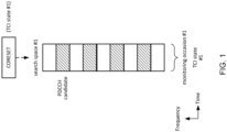
- a user terminal monitors PDCCH candidates.
- terminal User Equipment
- an object of the present disclosure is to provide a terminal, a radio communication method, and a base station capable of appropriately receiving a PDCCH.
- a terminal includes a receiving section that receives a media access control-control element (MAC CE) associating resources used for physical downlink control channel (PDCCH) candidates with a plurality of different transmission configuration indication (TCI) states, respectively, and a control section that monitors the PDCCH candidates by use of the corresponding TCI states.
- MAC CE media access control-control element
- TCI transmission configuration indication
- a PDCCH can be appropriately received.
- reception processing for example, at least one of reception, demapping, demodulation, and decoding
- transmission processing for example, at least one of transmission, mapping, precoding, modulation, and coding
- TCI state transmission configuration indication state
- the TCI state may be a state applied to a downlink signal/channel.
- a state that corresponds to the TCI state applied to an uplink signal/channel may be expressed as spatial relation.
- the TCI state is information related to quasi-co-location (QCL) of the signal/channel, and may be referred to as a spatial reception parameter, spatial relation information, or the like.
- the TCI state may be configured for the UE for each channel or for each signal.
- QCL is an indicator indicating statistical properties of the signal/channel. For example, when a given signal/channel and another signal/channel are in a relationship of QCL, it may be indicated that it is assumable that at least one of Doppler shift, a Doppler spread, an average delay, a delay spread, and a spatial parameter (for example, a spatial reception parameter (spatial Rx parameter)) is the same (the relationship of QCL is satisfied in at least one of these) between such a plurality of different signals/channels.
- a spatial parameter for example, a spatial reception parameter (spatial Rx parameter)
- the spatial reception parameter may correspond to a receive beam of the UE (for example, a receive analog beam), and the beam may be identified based on spatial QCL.
- the QCL (or at least one element in the relationship of QCL) in the present disclosure may be interpreted as sQCL (spatial QCL).
- QCL For the QCL, a plurality of types (QCL types) may be defined. For example, four QCL types A to D may be provided, which have different parameter(s) (or parameter set(s)) that can be assumed to be the same, and such parameter(s) (which may be referred to as QCL parameter(s)) are described below:
- a case that the UE assumes that a control resource set (CORESET), channel, or reference signal has a specific QCL (for example, QCL type D) relation with another CORESET, channel, or reference signal may be referred to as QCL assumption.
- CORESET control resource set
- QCL QCL type D
- the UE may determine at least one of a transmit beam (Tx beam) and a receive beam (Rx beam) of the signal/channel, based on the TCI state or the QCL assumption of the signal/channel.
- Tx beam transmit beam
- Rx beam receive beam
- the TCI state may be, for example, information related to QCL between a channel as a target (in other words, a reference signal (RS) for the channel) and another signal (for example, another RS).
- RS reference signal
- the TCI state may be configured (indicated) by higher layer signaling or physical layer signaling, or a combination of these.
- the physical layer signaling may be, for example, downlink control information (DCI).
- DCI downlink control information
- a channel for which the TCI state or the spatial relation is configured (indicated) may be, for example, at least one of a downlink shared channel (Physical Downlink Shared Channel (PDSCH)), a downlink control channel (Physical Downlink Control Channel (PDCCH)), an uplink shared channel (Physical Uplink Shared Channel (PUSCH)), and an uplink control channel (Physical Uplink Control Channel (PUCCH)).
- PDSCH Physical Downlink Shared Channel
- PDCCH Physical Downlink Control Channel
- PUSCH Physical Uplink Shared Channel
- PUCCH Physical Uplink Control Channel
- the RS to have a QCL relation with the channel may be, for example, at least one of a synchronization signal block (SSB), a channel state information reference signal (CSI-RS), a reference signal for measurement (sounding reference signal (SRS)), a tracking CSI-RS (also referred to as a tracking reference signal (TRS)), and a QCL detection reference signal (also referred to as a QRS).
- SSB synchronization signal block
- CSI-RS channel state information reference signal
- SRS sounding reference signal
- TRS tracking CSI-RS
- QRS QCL detection reference signal
- the SSB is a signal block including at least one of a primary synchronization signal (PSS), a secondary synchronization signal (SSS), and a broadcast channel (Physical Broadcast Channel (PBCH)).
- PSS primary synchronization signal
- SSS secondary synchronization signal
- PBCH Physical Broadcast Channel
- the SSB may be referred to as an SS/PBCH block.
- a QCL type X RS in a TCI state may mean an RS having a QCL type X relation with (a DMRS of) a channel/signal, and the RS may be referred to as a QCL source for the QCL type X in the TCI state.
- the TCI state of the PDSCH (default TCI state) may be the TCI state having the lowest CORESET ID in the most recent slot in the active DL BWP of a CC thereof (of a specific UL signal). Otherwise, the TCI state of the PDSCH (default TCI state) may be the TCI state having the lowest TCI state ID of the PDSCH in the active DL BWP of the scheduled CC.
- individual MAC CEs specifically a PUCCH spatial relation activation/deactivation MAC CE and an SRS spatial relation activation/deactivation MAC CE, are needed.
- the PUSCH spatial relation conforms to the SRS spatial relation.
- At least one of the PUCCH spatial relation activation/deactivation MAC CE and the SRS spatial relation activation/deactivation MAC CE may not be used.
- both the spatial relation and the PL-RS for a PUCCH are not configured in FR2 (application condition, second condition)
- default assumptions for the spatial relation and the PL-RS are applied to the PUCCH.
- both the spatial relation and the PL-RS for an SRS an SRS resource for the SRS, or an SRS resource corresponding to SRI in DCI format 0 1 scheduling the PUSCH
- FR2 application condition, second condition
- default assumptions for the spatial relation and the PL-RS are applied to the PUSCH scheduled by DCI format 0_1 and the SRS.
- the default spatial relation and the default PL-RS may be the TCI state or QCL assumption of the CORESET having the lowest CORESET ID in the active DL BWP. If a CORESET is not configured in the active DL BWP on the CC, the default spatial relation and the default PL-RS may be an active TCI state having the lowest ID of the PDSCH in the active DL BWP.
- the spatial relation of a PUSCH scheduled by DCI format 0_0 conforms to a spatial relation of a PUCCH resource having the lowest PUCCH resource ID among the PUCCH active spatial relations on the same CC.
- the network is required to update the PUCCH spatial relations on all SCells even in a case that a PUCCH is not transmitted on the SCells.
- a PUCCH configuration for the PUSCH scheduled by DCI format 0_0 is not required.
- the default spatial relation and the default PL-RS are applied to the PUSCH.
- the threshold described above may be referred to as a QCL time length (time duration), "timeDurationForQCL,” “Threshold”, “Threshold for offset between a DCI indicating a TCI state and a PDSCH scheduled by the DCI,” “Threshold-Sched-Offset,” a schedule offset threshold, a scheduling offset threshold, and the like.
- TRPs transmission/reception points
- MTRP multi-TRP
- MTRP multi-TRP
- UE uses one or a plurality of panels to perform UL transmission to one or the plurality of TRPs.
- the plurality of TRPs may correspond to the same cell identifier (cell ID), or different cell IDs.
- the cell ID may be a physical cell ID, or a virtual cell ID.
- the multi-TRP (for example, TRP #1, TRP #2) may be connected by an ideal/non-ideal backhaul to communicate information, data, or the like. From the respective TRPs of the multi-TRP, different code words (CW) and different layers may be transmitted. A non-coherent joint transmission (NCJT) may be used as one form of multi-TRP transmission.
- NJT non-coherent joint transmission
- TRP #1 performs modulation mapping and layer mapping of a first codeword, and transmits, by using a first precoding, a first number of layers (for example, two layers) on a first PDSCH.
- TRP #2 performs modulation mapping and layer mapping of a second codeword, and transmits, by using a second precoding, a second number of layers (for example, two layers) on a second PDSCH.
- a plurality of PDSCHs (multi-PDSCH) to be transmitted in the NCJT may be defined to partially or fully overlap in at least one of time and frequency domains.
- the first PDSCH from a first TRP and the second PDSCH from a second TRP may overlap each other in at least one of the time and frequency resources.
- first and second PDSCHs may be expected to be not in a quasi-co-location (QCL) relation (or to be not quasi-co-located) with each other.
- a reception of the multi-PDSCH may be interpreted as simultaneous reception of PDSCHs not in a given QCL type (for example, QCL type D).
- a plurality of PDSCHs (also referred to as multi-PDSCH (multiple PDSCH)) from the multi-TRP may be scheduled by using one piece of DCI (single DCI, single PDCCH) (single master mode).
- a plurality of PDSCHs from the multi-TRP may be scheduled respectively by using a plurality of pieces of DCI (multi-DCI, multi-PDCCH (multiple PDCCH)) (multi-master mode).
- one control resource set (CORESET) in PDCCH configuration information (PDCCH-Config) may correspond to one TRP in RRC configuration information for linking multiple PDCCH and PDSCH pairs with multi-TRP.
- FR 1 In frequency range (FR) 1, a block error rate (BLER) performance of PDCCH repetition using soft-combining and aggregation level (AL) 4 and a BLER performance of PDCCH repetition using soft-combining and AL8 are superior to a BLER performance of a single PDCCH using AL16 in all cases.
- the BLER performance of PDCCH repetition using soft-combining and AL4 a BLER performance of PDCCH repetition using selection and AL4
- the BLER performance of PDCCH repetition using soft-combining and AL8 are superior to the BLER performance of the single PDCCH using AL16.
- a BLER performance gain achieved by the repetition using selection is near the BLER performance of the reception using soft-combining.
- one PDCCH (PDCCH candidate) is associated with one search space set (search space).
- One search space set is associated with one CORESET with one TCI state/QCL assumption.
- the inventors of the present invention came up with a method for configuring/indicating/detecting a plurality of PDCCH candidates associated with different TCI states.
- the PDCCH repetition across a plurality of CORESETs may be performed to perform soft-combining of the PDCCH candidates.
- a search space set may be associated with a plurality of CORESETs.
- A/B and “at least one of A and B” may be interchangeably interpreted.
- a cell, a CC, a carrier, a BWP, a DL BWP, a UL BWP, an active DL BWP, an active UL BWP, and a band may be interchangeably interpreted.
- an index, ID, an indicator, and a resource ID may be interchangeably interpreted.
- RRC, an RRC parameter, an RRC message, a higher layer parameter, an information element (IE), and a configuration may be interchangeably interpreted.
- support “control,” “can control,” “operate,” and “can operate” may be interchangeably interpreted.
- activate, update, indicate, enable, and specify may be interchangeably interpreted.
- MAC CE an update command
- activation/deactivation command may be interchangeably interpreted.
- the higher layer signaling may be any one or combinations of Radio Resource Control (RRC) signaling, Medium Access Control (MAC) signaling, broadcast information, and the like.
- RRC Radio Resource Control
- MAC Medium Access Control
- the MAC signaling may use, for example, a MAC control element (MAC CE), a MAC Protocol Data Unit (PDU), or the like.
- the broadcast information may be, for example, a master information block (MIB), a system information block (SIB), minimum system information (Remaining Minimum System Information (RMSI)), other system information (OSI), or the like.
- MIB master information block
- SIB system information block
- RMSI Remaining Minimum System Information
- OSI system information
- a beam, a spatial domain filter, a TCI state, a QCL assumption, a QCL parameter, a spatial domain reception filter, a UE spatial domain reception filter, a UE receive beam, a DL beam, a DL receive beam, a DL precoding, a DL precoder, a DL-RS, a QCL type D in a TCI state, a QCL type D RS in a TCI state, a QCL type D RS in a TCI state or QCL assumption, a QCL type A RS in a TCI state or QCL assumption, a spatial relation, a spatial domain transmission filter, a UE spatial domain transmission filter, a UE transmit beam, a UL beam, a UL transmit beam, a UL precoding, and a UL precoder may be interchangeably interpreted.
- a QCL type X-RS, a DL-RS associated with a QCL type X, a DL-RS having a QCL type X, a source of a DL-RS, a SSB, and a CSI-RS may be interchangeably interpreted.
- a panel an Uplink (UL) transmission entity, a TRP, a spatial relation, a control resource set (CORESET), a PDSCH, a codeword, a base station, an antenna port of a signal (for example, demodulation reference signal (DMRS) port), an antenna port group of a signal (for example, DMRS port group), a group for multiplexing (for example, code division multiplexing (CDM) group, reference signal group, CORESET group), a CORESET pool, a CW, a redundancy version (RV), and a layer (MIMO layer, transmission layer, spatial layer) may be interchangeably interpreted.
- a panel Identifier (ID) and a panel may be interchangeably interpreted.
- a TRP ID and a TRP may be interchangeably interpreted.
- the UE configured with a plurality of TRPs may determine at least one of a TRP corresponding to the DCI, a TRP corresponding to a PDSCH or UL transmission (PUCCH, PUSCH, SRS, or the like) scheduled by the DCI, and the like, based on at least one of the following items.
- the single PDCCH may be referred to as the PDCCH (DCI) of a first scheduling type (for example, a scheduling type A (or type 1)).
- the multi-PDCCH may be referred to as the PDCCH (DCI) of a second scheduling type (for example, a scheduling type B (or type 2)).
- the single PDCCH may be expected to be supported in a case that an ideal backhaul is used by the multi-TRP.
- the multi-PDCCH may be expected to be supported in a case that a non-ideal backhaul is used between the multi-TRP.
- the ideal backhaul may be referred to as DMRS port group type 1, reference signal related group type 1, antenna port group type 1, CORESET pool type 1, or the like.
- the non-ideal backhaul may be referred to as DMRS port group type 2, reference signal related group type 2, antenna port group type 2, CORESET pool type 2, or the like.
- the names are not limited to those above.
- multi-TRP, multi-TRP system, multi-TRP transmission, and multi-PDSCH may be interchangeably interpreted.
- a single DCI, a single PDCCH, a single DCI based multi-TRP system, and two TCI states on at least one TCI code point being activated may be interchangeably interpreted.
- search space set and a search space (SS) may be interchangeably interpreted.
- Two sets of resource element group (REG)/control channel element (CCE)/monitoring occasion in one CORESET may include TCI states different from each other.
- One PDCCH candidate may include the REG/CCE from both two sets.
- the UE may follow at least one of operations 1-1 and 1-2 below.
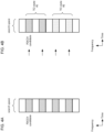
- a plurality of resources corresponding to one search space set may respectively include a plurality of different TCI states (or may be configured/indicated with a plurality of different TCI states).
- a resource may be interpreted as an REG/CCE/monitoring occasion (PDCCH monitoring occasion).
- a plurality of resources respectively corresponding to a plurality of different TCI states may be multiplexed by at least one of frequency division multiplexing (FDM), space division multiplexing (SDM), and time division multiplexing (TDM).
- FDM frequency division multiplexing
- SDM space division multiplexing
- TDM time division multiplexing
- a resource corresponding to the n-th TCI state may be referred to as the n-th resource.
- two sets of REG/CCE respectively correspond to two different TCI states #1, #2.
- a plurality of PDCCH candidates based on two sets may be FDMed.
- two monitoring occasions #1, #2 correspond to two different TCI states #1, #2, respectively.
- the PDCCH candidates being respectively associated with the monitoring occasions #1, #2 may cause a plurality of PDCCH candidates corresponding to two different TCI states #1, #2 to be TDMed.
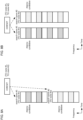
- two sets of REG/CCE respectively correspond to two different TCI states #1, #2.
- a plurality of PDCCH candidates based on two sets may be SDMed.
- a plurality of TCI states for one CORESET may be notified by the RRC/MAC CE.
- a plurality of TCI states may be assigned to a plurality of resources based on a rule.
- the rule may be at least one of assigning a plurality of TCI states in ascending order of the resource ID, assigning a plurality of TCI states in descending order of the resource ID, and assigning two TCI states to respectively the odd number and even number of the resource ID.
- the resource ID may be at least one of a search space ID, an REG index, and a CCE index.
- One TCI state per CORESET may be notified by the RRC/MAC CE.
- An additional TCI state for the CORESET or the search space set may be notified by the RRC/MAC CE.
- the CORESET may be associated with two TCI states.
- the TCI state notified by the mechanism in Rel. 15/16 may be a first TCI state
- the additional TCI state may be a second TCI state.
- the search space set may be associated with two TCI states.
- the TCI state notified by the mechanism in Rel. 15/16 may be the first TCI state
- the additional TCI state may be the second TCI state.
- the search space set not notified of the additional TCI state may be associated with only the TCI state notified by the mechanism in Rel. 15/16, and the UE may detect a PDCCH by the mechanism in Rel. 15/16. In this case, the UE may not try to perform blind detection of PDCCH by using different QCL type D.
- a plurality of TCI states being associated with one CORESET, and one or a plurality of or all of search space sets being associated with the CORESET may cause the one or plurality of or all of search space sets to be associated with the plurality of TCI states.
- the plurality of TCI states may be two TCI states, or three or more TCI states.
- the UE may follow any of procedures 1 and 2 below.
- the UE may use the indicated first TCI state to detect, by blind detection, some of the resources of the PDCCH candidates determined in accordance with Rel. 15/16, or may use the indicated second TCI state to detect, by blind detection, other resources of the resources of the PDCCH candidates determined in accordance with Rel. 15/16. According to the procedure 1, a resource size of the PDCCH candidates is not different from that in Rel. 15/16.
- the resources of a plurality of PDCCH candidates (time/frequency) in an example in FIG. 4A are determined in accordance with Rel. 15/16.
- a first part of the resources in FIG. 4A is associated with TCI state #1 and a second part is associated with TCI state #2.
- the UE may use TCI state #1 to detect, by blind detection, the first part and use TCI state #2 to detect, by blind detection, the second part.
- the UE may use the indicated first TCI state to detect, by blind detection, all of the resources of the PDCCH candidates determined in accordance with Rel. 15/16, or may use the indicated second TCI state to detect, by blind detection, other resources derived by the rule (for example, by giving an offset and copying). According to the procedure 2, such a problem as in FIG. 7 described later does not occur.
- a first resource in FIG. 4A is associated with TCI state #1
- a second resource obtained from the first resource by the rule is associated with TCI state #2.
- the UE may use TCI state #1 to detect, by blind detection, the first resource and use TCI state #2 to detect, by blind detection, the second resource.
- a plurality of monitoring occasions may correspond to (or may be configured for, or associated with) one search space set, the UE may determine (select) a monitoring occasion, based on the TCI state corresponding to the search space set.
- the REGs/CCEs corresponding to the respective monitoring occasions may be the same or different from each other.
- the REGs/CCEs may be determined using a conversion equation including an index of a symbol/slot/subslot/frame/subframe.
- the REGs/CCEs may be determined based on the notified information.
- monitoring occasions #1 to #64 the number of which is equal to the number of TCI states (for example, the number of SSBs) used in the cell may be configured, and monitoring occasions #1, #4 to be actually monitored may be determined (switched) depending on the notified TCI states.
- This method is preferable for a common search space (CSS) and broadcast.
- the monitoring occasions the number of which is equal to the number of TCI states configured for CORESET/search space set #1 may be configured, and monitoring occasions #1, #2 may be determined (switched) depending on TCI states #1, #4 used for the blind detection.
- an issue is that when the TCI states are different from each other in a plurality of PDCCH candidates within the same symbol and the AL is greater than a given value, which TCI state is used to perform blind detection of PDCCH.
- an issue is that in a case that the AL for the PDCCH candidates is 4, and TCI states #1, #2 are associated therein, which of TCI states #1 and #2 is used for blind detection.
- the UE may follow at least one of TCI state determination methods 1-1 to 1-6 below to perform blind detection of PDCCH.
- the UE may use the TCI state corresponding to the smallest or largest index of the plurality of REGs/CCEs in the AL for blind detection of PDCCH.
- the UE may use, in the plurality of REGs/CCEs in the AL, the TCI state corresponding to the smallest or largest index of the indices of the respective REGs/CCEs when the AL is 1 for blind detection of PDCCH.
- the UE may use the TCI state having the smallest or largest TCI state ID of the TCI states corresponding to the plurality of REGs/CCEs in the AL for blind detection of PDCCH.
- the UE may use, in the plurality of REGs/CCEs in the AL, the TCI state having the smallest or largest TCI state ID of the indices of the respective REGs/CCEs when the AL is 1 for blind detection of PDCCH.
- the UE may use the TCI state having the smallest or largest TCI state ID of the all configured/active TCI states in the DL-BWP/CC for blind detection of
- the UE may use the default TCI state for at least one of single TRP, single DCI for multi-TRP, and multi-DCI for multi-TRP for blind detection of PDCCH.
- the UE may use both two TCI states in the AL for blind detection of PDCCH.
- the UE reporting that simultaneous reception of PDCCH/PDSCH/CSI-RS using two TCI states is possible (is supported) through UE capability may use the TCI state determination method.
- the UE may not expect that in a search space set, the TCI states are different from each other in a plurality of PDCCH candidates within the same symbol, the AL is greater than a given value, and the TCI states for a plurality of REGs/CCEs in the AL are different from each other.
- One or a plurality of search space sets associated with different TCI states may be associated with (may correspond to) one CORESET.
- the search space sets associated with a plurality of different TCI states may be multiplexed by at least one of FDM/SDM/TDM.
- a search space set corresponding to the n-th TCI state may be referred to as the n-th search space set.
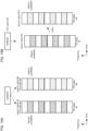
- one CORESET is associated with search spaces #1, #2.
- Search space #1 is associated with TCI state #1
- search space #2 is associated with TCI state #2.
- a PDCCH candidate for search space #1 and a PDCCH candidate for search space #2 are FDMed.
- a PDCCH candidate for search space #1 and a PDCCH candidate for search space #2 are TDMed.
- a PDCCH candidate for search space #1 and a PDCCH candidate for search space #2 are DDMed.
- the TCI state per search space set may be notified by the RRC/MAC CE.
- the TCI state for the search space set not configured with / not notified of the TCI state may be the TCI state configured/notified for the corresponding CORESET.
- One TCI state per CORESET may be notified by the RRC/MAC CE.
- An additional TCI state for the CORESET or the search space set may be notified by the RRC/MAC CE.
- the CORESET may be associated with two TCI states.
- the TCI state notified by the mechanism in Rel. 15/16 may be a first TCI state
- the additional TCI state may be a second TCI state.
- the search space set may be associated with two TCI states.
- the TCI state notified by the mechanism in Rel. 15/16 may be the first TCI state
- the additional TCI state may be the second TCI state.
- the search space set not notified of the additional TCI state may be associated with only the TCI state notified by the mechanism in Rel. 15/16, and the UE may detect a PDCCH by the mechanism in Rel. 15/16. In this case, the UE may not try to perform blind detection of PDCCH by using different QCL type D.
- the TCI state may not be notified per CORESET. Even if the TCI state is notified per CORESET, the TCI state notified per CORESET may not be applied to at least some of the search space sets.
- the TCI state notified per search space set may be applied to, or the TCI state notified per CORESET may not be applied to the search space set configured with/notified of the TCI state.
- the TCI state per search space set may follow at least one of notification methods 1 and 2 below.
- the higher layer signaling (information element) indicating each search space set may include a TCI state field.
- the TCI states different for each search space set may be configured/notified by the higher layer signaling.
- one CORESET is associated with search spaces #1, #2.
- Search space #1 is associated with TCI state #1
- search space #2 is associated with TCI state #2.
- Search spaces #1 and 2 may be FDMed/TDMed/SDMed.
- the UE detects, by blind detection, a PDCCH candidate for search space #1 by use of TCI state #1, and detects, by blind detection, a PDCCH candidate for search space #2 by use of TCI state #2.
- the TCI state for the first search space set may be the first TCI state configured/notified for the CORESET.
- the TCI state for the second search space set obtained from the first search space set (by copying to another time/frequency) based on a rule may be the second TCI state configured/notified by the higher layer signaling.
- one CORESET is associated with search space #1.
- Search space #1 is associated with TCI state #1.
- a resource of a PDCCH candidate for search space #1a is obtained from the resource of the PDCCH candidate for search space #1 based on the rule.
- Search space #1a is associated with TCI state #2.
- the UE detects, by blind detection, the PDCCH candidate for search space #1 by use of TCI state #1, and detects, by blind detection, the PDCCH candidate for search space #1a by use of TCI state #2.
- one CORESET is associated with search spaces #1, #2.
- Search space #1 is associated with TCI state #1
- search space #2 is associated with TCI state #2.
- the resource of the PDCCH candidate for search space #1 and the resource of the PDCCH candidate for search space #2 overlap.
- the UE may follow at least one of TCI state determination methods 2-1 to 2-6 below to perform blind detection of
- the UE may use the TCI state corresponding to the smallest or largest search space set ID of the search space sets corresponding to the overlapping resources for blind detection of PDCCH.
- the UE may use the TCI state having the smallest or largest TCI state ID of the search space sets corresponding to the overlapping resources for blind detection of PDCCH.
- the UE may use the TCI state having the smallest or largest TCI state ID of the all configured/active TCI states in the DL-BWP/CC for blind detection of PDCCH.
- the UE may use the default TCI state for at least one of single TRP, single DCI for multi-TRP, and multi-DCI for multi-TRP for blind detection of PDCCH.
- the UE may use both two TCI states respectively associated with two search space sets for blind detection of PDCCH.
- the UE reporting that simultaneous reception of PDCCH/PDSCH/CSI-RS using two TCI states is possible (is supported) through UE capability may use the TCI state determination method.
- the UE may not expect that the PDCCH candidates for a plurality of search space sets associated with different TCI states are configured in the same symbol, or the resources of the PDCCH candidates for the search space sets associated with different TCI states overlap. In other words, the resources of the PDCCH candidates for search space sets associated with different TCI states may not overlap.
- the TCI state for the PDCCH can be appropriately determined.
- a new MAC CE may notify a plurality of TCI stated per CORESET, or one or a plurality of TCI states per search space set.
- the new MAC CE may follow at least one of MAC CEs 1 to 3 below.
- the new MAC CE may notify a plurality of TCI states per CORESET.
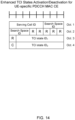
- the new MAC CE may be referred to as an enhanced TCI states activation/deactivation for UE-specific PDCCH MAC CE.
- the new MAC CE may include at least one of a serving cell ID field, a CORESET ID field, a TCI state ID 1 field, a C field, and a TCI state ID 2 field.
- the C field may indicate whether or not the TCI state ID 2 field (an octet including the TCI state ID 2 field) exists. For example, in a case that the C field is set to 1, the TCI state ID 2 field (an octet including the TCI state ID 2 field) may exist, and in a case that the C field is set to 0, the TCI state ID 2 field (an octet including the TCI state ID 2 field) may not exist.
- a TCI state ID j field may indicate the j-th TCI state, and may indicate a TCI state identified by a TCI state ID applicable to a CORESET identified by the CORESET ID field.
- the TCI state ID field may indicate a TCI state for one TCI state among the first 64 TCI states configured by a TCI state addition/modification list (tci-State-ToAddModList) and a TCI state release list (tci-States-ToReleaseList) in a PDSCH configuration (PDSCH-Config) in an active BWP.
- the TCI state ID field may indicate a TCI state ID configured by a TCI state for PDCCH addition list (tci-StatesPDCCH-ToAddList) and a TCI state for PDCCH release list (tci-StatesPDCCH-ToReleaseList) in a CORESET configuration identified by the indicated CORESET.
- the C field may be included not in an octet 3 but in an octet 2.
- a size of at least one of the serving cell ID field, the CORESET ID field, and the TCI state ID j field may be limited.
- the number of TCI states indicated by the new MAC CE is not limited to two.
- the number of TCI states indicated by the new MAC CE and the number of octets of the new MAC CE may be variable depending on the number configured by the higher layer or the number reported through the UE capability.
- the UE receiving the new MAC CE may not receive a TCI states indication for UE-specific PDCCH MAC CE.
- the UE may apply only the last received MAC CE, or may apply the new MAC CE on a priority basis.
- the new MAC CE may notify one TCI state per search space set.
- the new MAC CE may be referred to as an enhanced TCI states activation/deactivation for UE-specific PDCCH MAC CE.
- the new MAC CE may include at least one of a serving cell ID field, a search space ID field, a reserved (R) field, and a TCI state ID field.
- the search space ID field may indicate a search space identified by a search space ID information element.
- the TCI state ID field may indicate a TCI state applicable to the search space identified by the search space ID field. In a case that the search space ID field (or the CORESET ID associated with the search space ID) is set to 0, the TCI state ID field may indicate a TCI state for one TCI state among the first 64 TCI states configured by the TCI state addition/modification list and the TCI state release list in the PDSCH configuration in an active BWP.
- the TCI state ID field may indicate a TCI state ID configured by the TCI state for PDCCH addition list and the TCI state for PDCCH release list in a CORESET configuration identified by the corresponding CORESET.
- the search space ID can be configured with up to 40 values per cell, and is an ID unique to all BWPs. Accordingly, the search space ID field may include six bits.
- the TCI state addition/modification list and the TCI state release list may be configured.
- the TCI state ID field may indicate a TCI state ID configured by the TCI state addition/modification list and the TCI state release list in the search space configuration identified by the search space ID field.
- the new MAC CE may notify a plurality of TCI states per search space set.
- the new MAC CE may include at least one of a serving cell ID field, a search space ID field, a reserved (R) field, a TCI state ID 1 field, a C field, and a TCI state ID 2 field.
- the C field may indicate whether or not the TCI state ID 2 field (an octet including the TCI state ID 2 field) exists. For example, in a case that the C field is set to 1, the TCI state ID 2 field (an octet including the TCI state ID 2 field) may exist, and in a case that the C field is set to 0, the TCI state ID 2 field (an octet including the TCI state ID 2 field) may not exist.
- the search space ID field may indicate a search space identified by a search space ID information element.
- a TCI state ID j field may indicate the j-th TCI state, and may indicate a TCI state identified by a TCI state ID applicable to the search space identified by the search space ID field.
- the search space ID field (or the CORESET ID associated with the search space ID) is set to 0
- the TCI state ID field may indicate a TCI state for one TCI state among the first 64 TCI states configured by the TCI state addition/modification list and the TCI state release list in the PDSCH configuration in an active BWP.
- the TCI state ID field may indicate a TCI state ID configured by the TCI state for PDCCH addition list and the TCI state for PDCCH release list in a CORESET configuration identified by the corresponding CORESET.
- the R field in an octet 3 may be replaced with the C field
- the C field in an octet 4 may be replaced with the R field
- the number of bits of the search space ID field may be limited. This can reduce overhead for the MAC CE.
- the new MAC CE may include at least one of a serving cell ID field, a search space ID field, and a TCI state ID field.
- the search space ID field may indicate a search space identified by a search space ID information element.
- the TCI state ID field may indicate a TCI state applicable to the search space identified by the search space ID field. In a case that the search space ID field (or the CORESET ID associated with the search space ID) is set to 0, the TCI state ID field may indicate a TCI state for one TCI state among the first 64 TCI states configured by the TCI state addition/modification list and the TCI state release list in the PDSCH configuration in an active BWP.
- the TCI state ID field may indicate a TCI state ID configured by the TCI state for PDCCH addition list and the TCI state for PDCCH release list in a CORESET configuration identified by the corresponding CORESET.
- a list of up to 16 search space IDs capable of indicating the TCI state per search space set may configured by the RRC.
- An index corresponding to ascending or descending order of a value of the search space ID in the configured list may be indicated by the search space ID field in the new MAC CE.
- the list of the search space ID may not be configured by the RRC.
- the search space configuration may include the TCI state ID.
- An index corresponding to ascending or descending order of a value of the search space ID of the search space configured with the TCI state may be indicated by the search space ID field in the new MAC CE.
- the new MAC CE may notify the CORESET of an additional TCI state.
- the new MAC CE may be referred to as an additional TCI states activation/deactivation for UE-specific PDCCH MAC CE.
- the new MAC CE may include at least one of a serving cell ID field, a CORESET ID field, a TCI state ID 1 field, a C field, and a TCI state ID 2 field.
- the C field may indicate whether or not the TCI state ID 2 field (an octet including the TCI state ID 2 field) exists. For example, in a case that the C field is set to 1, the TCI state ID 2 field (an octet including the TCI state ID 2 field) may exist, and in a case that the C field is set to 0, the TCI state ID 2 field (an octet including the TCI state ID 2 field) may not exist.
- a TCI state ID j field may indicate the j-th TCI state, and may indicate a TCI state identified by a TCI state ID applicable to a CORESET identified by the CORESET ID field.
- the TCI state ID field may indicate a TCI state for one TCI state among the first 64 TCI states configured by a TCI state addition/modification list (tci-State-ToAddModList) and a TCI state release list (tci-States-ToReleaseList) in a PDSCH configuration (PDSCH-Config) in an active BWP.
- the TCI state ID field may indicate a TCI state ID configured by a TCI state for PDCCH addition list (tci-StatesPDCCH-ToAddList) and a TCI state for PDCCH release list (tci-StatesPDCCH-ToReleaseList) in a CORESET configuration identified by the indicated CORESET.
- the C field may be included not in an octet 3 but in an octet 2.
- a size of at least one of the serving cell ID field, the CORESET ID field, and the TCI state ID j field may be limited.
- a TCI state notified for a CORESET by the mechanism in Rel. 15/16 may be a 0-th TCI state.
- the additional TCI state may be notified for the CORESET by the new MAC CE. In this case, up to two additional TCI states per CORESET are notified by the new MAC CE, but three or more additional TCI states may be notified.
- the number of TCI states (additional TCI states) notified by the new MAC CE and the number of octets of the new MAC CE may be variable depending on the number configured by the higher layer signaling or the number reported through the UE capability.
- the TCI state for the PDCCH can be appropriately determined.
- At least one of the first and second embodiments may be applied to only the UE reporting the corresponding UE capability.
- the UE capability may be defined in Rel. 17, or may be capability for PDCCH multi-TRP (for reliability improvement).
- At least one of the first and second embodiments may include a case that two PDCCH candidates with different QCL type D are detected simultaneously by blind detection (for example, in the same symbol). This operation may be applied to only the UE reporting the UE capability indicating that this operation is possible (is supported).
- the UE capability may be at least one of capabilities 1 to 3 below.
- the n-th TRP, the n-th TCI state, the n-th CDM group, the n-th CORESET group, and the n-th CORESET pool may be interchangeably interpreted.
- a search space ID 0 (search space 0) and a search space configured by a PBCH (MIB) or a serving cell common configuration (ServingCellConfigCommon).
- the CORESET 0 is used for an initial access, but the initial access assumes one QCL (in the specification in Rel. 15), and thus, the CORESET 0 may always include one TCI state/QCL assumption.
- At least one of the first and second embodiments may be applied to a CORESET other than the CORESET 0.
- At least one of the first and second embodiments may be applied to at least one of a UE-specific search space (USS) and a CORESET corresponding thereto. At least one of the first and second embodiments may not be applied to at least one of a common search space (CSS) and a common CORESET.
- USS UE-specific search space
- CSS common search space
- radio communication system a structure of a radio communication system according to one embodiment of the present disclosure will be described.
- the radio communication method according to each embodiment of the present disclosure described above may be used alone or may be used in combination for communication.
- FIG. 17 is a diagram to show an example of a schematic structure of the radio communication system according to one embodiment.
- the radio communication system 1 may be a system implementing a communication using Long Term Evolution (LTE), 5th generation mobile communication system New Radio (5G NR) and so on the specifications of which have been drafted by Third Generation Partnership Project (3GPP).
- LTE Long Term Evolution
- 5G NR 5th generation mobile communication system New Radio
- the radio communication system 1 may support dual connectivity (multi-RAT dual connectivity (MR-DC)) between a plurality of Radio Access Technologies (RATs).
- the MR-DC may include dual connectivity (E-UTRA-NR Dual Connectivity (EN-DC)) between LTE (Evolved Universal Terrestrial Radio Access (E-UTRA)) and NR, dual connectivity (NR-E-UTRA Dual Connectivity (NE-DC)) between NR and LTE, and so on.
- a base station (eNB) of LTE (E-UTRA) is a master node (MN), and a base station (gNB) of NR is a secondary node (SN).
- a base station (gNB) of NR is an MN
- a base station (eNB) of LTE (E-UTRA) is an SN.
- the radio communication system 1 may support dual connectivity between a plurality of base stations in the same RAT (for example, dual connectivity (NR-NR Dual Connectivity (NN-DC)) where both of an MN and an SN are base stations (gNB) of NR).
- dual connectivity NR-NR Dual Connectivity (NN-DC)
- gNB base stations
- the radio communication system 1 may include a base station 11 that forms a macro cell C1 of a relatively wide coverage, and base stations 12 (12a to 12c) that form small cells C2, which are placed within the macro cell C1 and which are narrower than the macro cell C1.
- the user terminal 20 may be located in at least one cell.
- the arrangement, the number, and the like of each cell and user terminal 20 are by no means limited to the aspect shown in the diagram.
- the base stations 11 and 12 will be collectively referred to as "base stations 10," unless specified otherwise.
- the user terminal 20 may be connected to at least one of the plurality of base stations 10.
- the user terminal 20 may use at least one of carrier aggregation (CA) and dual connectivity (DC) using a plurality of component carriers (CCs).
- CA carrier aggregation
- DC dual connectivity
- CCs component carriers
- Each CC may be included in at least one of a first frequency band (Frequency Range 1 (FR1)) and a second frequency band (Frequency Range 2 (FR2)).
- the macro cell C1 may be included in FR1
- the small cells C2 may be included in FR2.
- FR1 may be a frequency band of 6 GHz or less (sub-6 GHz)
- FR2 may be a frequency band which is higher than 24 GHz (above-24 GHz). Note that frequency bands, definitions and so on of FR1 and FR2 are by no means limited to these, and for example, FR1 may correspond to a frequency band which is higher than FR2.
- the user terminal 20 may communicate using at least one of time division duplex (TDD) and frequency division duplex (FDD) in each CC.
- TDD time division duplex
- FDD frequency division duplex
- the plurality of base stations 10 may be connected by a wired connection (for example, optical fiber in compliance with the Common Public Radio Interface (CPRI), the X2 interface and so on) or a wireless connection (for example, an NR communication).
- a wired connection for example, optical fiber in compliance with the Common Public Radio Interface (CPRI), the X2 interface and so on
- a wireless connection for example, an NR communication
- IAB Integrated Access Backhaul
- relay station relay station
- the base station 10 may be connected to a core network 30 through another base station 10 or directly.
- the core network 30 may include at least one of Evolved Packet Core (EPC), 5G Core Network (5GCN), Next Generation Core (NGC), and so on.
- EPC Evolved Packet Core
- 5GCN 5G Core Network
- NGC Next Generation Core
- the user terminal 20 may be a terminal supporting at least one of communication schemes such as LTE, LTE-A, 5G, and so on.
- an orthogonal frequency division multiplexing (OFDM)-based wireless access scheme may be used.
- OFDM Orthogonal frequency division multiplexing
- DL downlink
- UL uplink
- DFT-s-OFDM Discrete Fourier Transform Spread OFDM
- OFDMA Orthogonal Frequency Division Multiple Access
- SC-FDMA Single Carrier Frequency Division Multiple Access
- the wireless access scheme may be referred to as a "waveform.”
- another wireless access scheme for example, another single carrier transmission scheme, another multi-carrier transmission scheme
- a downlink shared channel (Physical Downlink Shared Channel (PDSCH)), which is used by each user terminal 20 on a shared basis, a broadcast channel (Physical Broadcast Channel (PBCH)), a downlink control channel (Physical Downlink Control Channel (PDCCH)) and so on, may be used as downlink channels.
- PDSCH Physical Downlink Shared Channel
- PBCH Physical Broadcast Channel
- PDCCH Physical Downlink Control Channel
- an uplink shared channel (Physical Uplink Shared Channel (PUSCH)), which is used by each user terminal 20 on a shared basis, an uplink control channel (Physical Uplink Control Channel (PUCCH)), a random access channel (Physical Random Access Channel (PRACH)) and so on may be used as uplink channels.
- PUSCH Physical Uplink Shared Channel
- PUCCH Physical Uplink Control Channel
- PRACH Physical Random Access Channel
- SIBs System Information Blocks
- PBCH Master Information Blocks
- Lower layer control information may be communicated on the PDCCH.
- the lower layer control information may include downlink control information (DCI) including scheduling information of at least one of the PDSCH and the PUSCH.
- DCI downlink control information
- DCI for scheduling the PDSCH may be referred to as "DL assignment,” “DL DCI,” and so on, and DCI for scheduling the PUSCH may be referred to as "UL grant,” “UL DCI,” and so on.
- DL assignment DCI for scheduling the PDSCH
- UL grant DCI for scheduling the PUSCH
- the PDSCH may be interpreted as “DL data”
- the PUSCH may be interpreted as "UL data”.
- a control resource set (CORESET) and a search space may be used.
- the CORESET corresponds to a resource to search DCI.
- the search space corresponds to a search area and a search method of PDCCH candidates.
- One CORESET may be associated with one or more search spaces.
- the UE may monitor a CORESET associated with a given search space, based on search space configuration.
- One search space may correspond to a PDCCH candidate corresponding to one or more aggregation levels.
- One or more search spaces may be referred to as a "search space set.” Note that a "search space,” a “search space set,” a “search space configuration,” a “search space set configuration,” a “CORESET,” a “CORESET configuration” and so on of the present disclosure may be interchangeably interpreted.
- Uplink control information including at least one of channel state information (CSI), transmission confirmation information (for example, which may be also referred to as Hybrid Automatic Repeat reQuest ACKnowledgement (HARQ-ACK), ACK/NACK, and so on), and scheduling request (SR) may be communicated by means of the PUCCH.
- CSI channel state information
- HARQ-ACK Hybrid Automatic Repeat reQuest ACKnowledgement
- ACK/NACK ACK/NACK
- SR scheduling request
- downlink may be expressed without a term of "link.”
- various channels may be expressed without adding "Physical” to the head.
- a synchronization signal (SS), a downlink reference signal (DL-RS), and so on may be communicated.
- a cell-specific reference signal (CRS), a channel state information-reference signal (CSI-RS), a demodulation reference signal (DMRS), a positioning reference signal (PRS), a phase tracking reference signal (PTRS), and so on may be communicated as the DL-RS.
- CRS cell-specific reference signal
- CSI-RS channel state information-reference signal
- DMRS demodulation reference signal
- PRS positioning reference signal
- PTRS phase tracking reference signal
- the synchronization signal may be at least one of a primary synchronization signal (PSS) and a secondary synchronization signal (SSS).
- a signal block including an SS (PSS, SSS) and a PBCH (and a DMRS for a PBCH) may be referred to as an "SS/PBCH block,” an "SS Block (SSB),” and so on.
- SS/PBCH block an "SS Block (SSB),” and so on.
- SSB SS Block
- a sounding reference signal (SRS), a demodulation reference signal (DMRS), and so on may be communicated as an uplink reference signal (UL-RS).
- SRS sounding reference signal
- DMRS demodulation reference signal
- UL-RS uplink reference signal
- DMRS may be referred to as a "user terminal specific reference signal (UE-specific Reference Signal).”
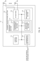
- FIG. 18 is a diagram to show an example of a structure of the base station according to one embodiment.
- the base station 10 includes a control section 110, a transmitting/receiving section 120, transmitting/receiving antennas 130 and a communication path interface (transmission line interface) 140.
- the base station 10 may include one or more control sections 110, one or more transmitting/receiving sections 120, one or more transmitting/receiving antennas 130, and one or more communication path interfaces 140.
- the present example primarily shows functional blocks that pertain to characteristic parts of the present embodiment, and it is assumed that the base station 10 may include other functional blocks that are necessary for radio communication as well. Part of the processes of each section described below may be omitted.
- the control section 110 controls the whole of the base station 10.
- the control section 110 can be constituted with a controller, a control circuit, or the like described based on general understanding of the technical field to which the present disclosure pertains.
- the control section 110 may control generation of signals, scheduling (for example, resource allocation, mapping), and so on.
- the control section 110 may control transmission and reception, measurement and so on using the transmitting/receiving section 120, the transmitting/receiving antennas 130, and the communication path interface 140.
- the control section 110 may generate data, control information, a sequence and so on to transmit as a signal, and forward the generated items to the transmitting/receiving section 120.
- the control section 110 may perform call processing (setting up, releasing) for communication channels, manage the state of the base station 10, and manage the radio resources.
- the transmitting/receiving section 120 may include a baseband section 121, a Radio Frequency (RF) section 122, and a measurement section 123.
- the baseband section 121 may include a transmission processing section 1211 and a reception processing section 1212.
- the transmitting/receiving section 120 can be constituted with a transmitter/receiver, an RF circuit, a baseband circuit, a filter, a phase shifter, a measurement circuit, a transmitting/receiving circuit, or the like described based on general understanding of the technical field to which the present disclosure pertains.
- the transmitting/receiving section 120 may be structured as a transmitting/receiving section in one entity, or may be constituted with a transmitting section and a receiving section.
- the transmitting section may be constituted with the transmission processing section 1211, and the RF section 122.
- the receiving section may be constituted with the reception processing section 1212, the RF section 122, and the measurement section 123.
- the transmitting/receiving antennas 130 can be constituted with antennas, for example, an array antenna, or the like described based on general understanding of the technical field to which the present disclosure pertains.
- the transmitting/receiving section 120 may transmit the above-described downlink channel, synchronization signal, downlink reference signal, and so on.
- the transmitting/receiving section 120 may receive the above-described uplink channel, uplink reference signal, and so on.
- the transmitting/receiving section 120 may form at least one of a transmit beam and a receive beam by using digital beam forming (for example, precoding), analog beam forming (for example, phase rotation), and so on.
- digital beam forming for example, precoding
- analog beam forming for example, phase rotation
- the transmitting/receiving section 120 may perform the processing of the Packet Data Convergence Protocol (PDCP) layer, the processing of the Radio Link Control (RLC) layer (for example, RLC retransmission control), the processing of the Medium Access Control (MAC) layer (for example, HARQ retransmission control), and so on, for example, on data and control information and so on acquired from the control section 110, and may generate bit string to transmit.
- PDCP Packet Data Convergence Protocol
- RLC Radio Link Control
- MAC Medium Access Control
- the transmitting/receiving section 120 may perform transmission processing such as channel coding (which may include error correction coding), modulation, mapping, filtering, discrete Fourier transform (DFT) processing (as necessary), inverse fast Fourier transform (IFFT) processing, precoding, digital-to-analog conversion, and so on, on the bit string to transmit, and output a baseband signal.
- transmission processing such as channel coding (which may include error correction coding), modulation, mapping, filtering, discrete Fourier transform (DFT) processing (as necessary), inverse fast Fourier transform (IFFT) processing, precoding, digital-to-analog conversion, and so on, on the bit string to transmit, and output a baseband signal.
- the transmitting/receiving section 120 may perform modulation to a radio frequency band, filtering, amplification, and so on, on the baseband signal, and transmit the signal of the radio frequency band through the transmitting/receiving antennas 130.
- the transmitting/receiving section 120 may perform amplification, filtering, demodulation to a baseband signal, and so on, on the signal of the radio frequency band received by the transmitting/receiving antennas 130.
- the transmitting/receiving section 120 may apply reception processing such as analog-digital conversion, fast Fourier transform (FFT) processing, inverse discrete Fourier transform (IDFT) processing (as necessary), filtering, de-mapping, demodulation, decoding (which may include error correction decoding), MAC layer processing, the processing of the RLC layer and the processing of the PDCP layer, and so on, on the acquired baseband signal, and acquire user data, and so on.
- reception processing such as analog-digital conversion, fast Fourier transform (FFT) processing, inverse discrete Fourier transform (IDFT) processing (as necessary), filtering, de-mapping, demodulation, decoding (which may include error correction decoding), MAC layer processing, the processing of the RLC layer and the processing of the PDCP layer, and so on, on the acquired baseband signal, and acquire user data, and so on.
- FFT fast Fourier transform
- IDFT inverse discrete Fourier transform
- filtering de-mapping
- demodulation which
- the transmitting/receiving section 120 may perform the measurement related to the received signal.
- the measurement section 123 may perform Radio Resource Management (RRM) measurement, Channel State Information (CSI) measurement, and so on, based on the received signal.
- the measurement section 123 may measure a received power (for example, Reference Signal Received Power (RSRP)), a received quality (for example, Reference Signal Received Quality (RSRQ), a Signal to Interference plus Noise Ratio (SINR), a Signal to Noise Ratio (SNR)), a signal strength (for example, Received Signal Strength Indicator (RSSI)), channel information (for example, CSI), and so on.
- the measurement results may be output to the control section 110.
- the communication path interface 140 may perform transmission/reception (backhaul signaling) of a signal with an apparatus included in the core network 30 or other base stations 10, and so on, and acquire or transmit user data (user plane data), control plane data, and so on for the user terminal 20.
- backhaul signaling backhaul signaling
- the transmitting section and the receiving section of the base station 10 in the present disclosure may be constituted with at least one of the transmitting/receiving section 120, the transmitting/receiving antennas 130, and the communication path interface 140.
- the transmitting/receiving section 120 may transmit information associating a plurality of physical downlink control channel (PDCCH) candidates with a plurality of different transmission configuration indication (TCI) states, respectively.
- the control section 110 may control a PDCCH transmission using a corresponding TCI state.
- the transmitting/receiving section 120 may transmit a media access control-control element (MAC CE) associating resources used for the physical downlink control channel (PDCCH) candidates with a plurality of different transmission configuration indication (TCI) states, respectively.
- the control section 110 may control a PDCCH transmission using a corresponding TCI state.
- MAC CE media access control-control element
- TCI transmission configuration indication
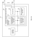
- FIG. 19 is a diagram to show an example of a structure of the user terminal according to one embodiment.
- the user terminal 20 includes a control section 210, a transmitting/receiving section 220, and transmitting/receiving antennas 230. Note that the user terminal 20 may include one or more control sections 210, one or more transmitting/receiving sections 220, and one or more transmitting/receiving antennas 230.
- the present example primarily shows functional blocks that pertain to characteristic parts of the present embodiment, and it is assumed that the user terminal 20 may include other functional blocks that are necessary for radio communication as well. Part of the processes of each section described below may be omitted.
- the control section 210 controls the whole of the user terminal 20.
- the control section 210 can be constituted with a controller, a control circuit, or the like described based on general understanding of the technical field to which the present disclosure pertains.
- the control section 210 may control generation of signals, mapping, and so on.
- the control section 210 may control transmission/reception, measurement and so on using the transmitting/receiving section 220, and the transmitting/receiving antennas 230.
- the control section 210 generates data, control information, a sequence and so on to transmit as a signal, and may forward the generated items to the transmitting/receiving section 220.
- the transmitting/receiving section 220 may include a baseband section 221, an RF section 222, and a measurement section 223.
- the baseband section 221 may include a transmission processing section 2211 and a reception processing section 2212.
- the transmitting/receiving section 220 can be constituted with a transmitter/receiver, an RF circuit, a baseband circuit, a filter, a phase shifter, a measurement circuit, a transmitting/receiving circuit, or the like described based on general understanding of the technical field to which the present disclosure pertains.
- the transmitting/receiving section 220 may be structured as a transmitting/receiving section in one entity, or may be constituted with a transmitting section and a receiving section.
- the transmitting section may be constituted with the transmission processing section 2211 and the RF section 222.
- the receiving section may be constituted with the reception processing section 2212, the RF section 222, and the measurement section 223.
- the transmitting/receiving antennas 230 can be constituted with antennas, for example, an array antenna, or the like described based on general understanding of the technical field to which the present disclosure pertains.
- the transmitting/receiving section 220 may receive the above-described downlink channel, synchronization signal, downlink reference signal, and so on.
- the transmitting/receiving section 220 may transmit the above-described uplink channel, uplink reference signal, and so on.
- the transmitting/receiving section 220 may form at least one of a transmit beam and a receive beam by using digital beam forming (for example, precoding), analog beam forming (for example, phase rotation), and so on.
- digital beam forming for example, precoding
- analog beam forming for example, phase rotation
- the transmitting/receiving section 220 may perform the processing of the PDCP layer, the processing of the RLC layer (for example, RLC retransmission control), the processing of the MAC layer (for example, HARQ retransmission control), and so on, for example, on data and control information and so on acquired from the control section 210, and may generate bit string to transmit.
- the transmitting/receiving section 220 may perform transmission processing such as channel coding (which may include error correction coding), modulation, mapping, filtering, DFT processing (as necessary), IFFT processing, precoding, digital-to-analog conversion, and so on, on the bit string to transmit, and output a baseband signal.
- transmission processing such as channel coding (which may include error correction coding), modulation, mapping, filtering, DFT processing (as necessary), IFFT processing, precoding, digital-to-analog conversion, and so on, on the bit string to transmit, and output a baseband signal.
- the transmitting/receiving section 220 may perform, for a given channel (for example, PUSCH), the DFT processing as the above-described transmission processing to transmit the channel by using a DFT-s-OFDM waveform if transform precoding is enabled, and otherwise, does not need to perform the DFT processing as the above-described transmission process.
- a given channel for example, PUSCH
- the transmitting/receiving section 220 may perform modulation to a radio frequency band, filtering, amplification, and so on, on the baseband signal, and transmit the signal of the radio frequency band through the transmitting/receiving antennas 230.
- the transmitting/receiving section 220 may perform amplification, filtering, demodulation to a baseband signal, and so on, on the signal of the radio frequency band received by the transmitting/receiving antennas 230.
- the transmitting/receiving section 220 may apply a receiving process such as analog-digital conversion, FFT processing, IDFT processing (as necessary), filtering, de-mapping, demodulation, decoding (which may include error correction decoding), MAC layer processing, the processing of the RLC layer and the processing of the PDCP layer, and so on, on the acquired baseband signal, and acquire user data, and so on.
- a receiving process such as analog-digital conversion, FFT processing, IDFT processing (as necessary), filtering, de-mapping, demodulation, decoding (which may include error correction decoding), MAC layer processing, the processing of the RLC layer and the processing of the PDCP layer, and so on, on the acquired baseband signal, and acquire user data, and so on.
- the transmitting/receiving section 220 may perform the measurement related to the received signal.
- the measurement section 223 may perform RRM measurement, CSI measurement, and so on, based on the received signal.
- the measurement section 223 may measure a received power (for example, RSRP), a received quality (for example, RSRQ, SINR, SNR), a signal strength (for example, RSSI), channel information (for example, CSI), and so on.
- the measurement results may be output to the control section 210.
- the transmitting section and the receiving section of the user terminal 20 in the present disclosure may be constituted with at least one of the transmitting/receiving section 220, the transmitting/receiving antennas 230, and the communication path interface 240.
- the transmitting/receiving section 220 may receive information associating a plurality of physical downlink control channel (PDCCH) candidates with a plurality of different transmission configuration indication (TCI) states, respectively.
- the control section 210 may monitor at least one of the plurality of PDCCH candidates by use of a corresponding TCI state, based on the information.
- PDCCH physical downlink control channel
- TCI transmission configuration indication
- a plurality of sets of resources in one control resource set may be respectively associated with the plurality of different TCI states.
- One search space set may be associated with the one control resource set, the one search space set may include a plurality of PDCCH monitoring occasions, and the plurality of PDCCH monitoring occasions may be respectively associated with the plurality of different TCI states.
- Two search space sets may be associated with one control resource set, and the two search space sets may include two different TCI states.
- the transmitting/receiving section 220 may receive a media access control-control element (MAC CE) associating resources used for the physical downlink control channel (PDCCH) candidates with a plurality of different transmission configuration indication (TCI) states, respectively.
- the control section 210 may monitor the PDCCH candidate by use of the corresponding TCI state.
- MAC CE media access control-control element
- TCI transmission configuration indication
- the MAC CE may associate one control resource set with the plurality of different TCI states.
- the MAC CE may associate one search space set with one of the plurality of different TCI states.
- the MAC CE may associate one search space set with the plurality of different TCI states.
- each functional block may be realized by one piece of apparatus that is physically or logically coupled, or may be realized by directly or indirectly connecting two or more physically or logically separate pieces of apparatus (for example, via wire, wireless, or the like) and using these plurality of pieces of apparatus.
- the functional blocks may be implemented by combining software into the apparatus described above or the plurality of apparatuses described above.
- functions include judgment, determination, decision, calculation, computation, processing, derivation, investigation, search, confirmation, reception, transmission, output, access, resolution, selection, designation, establishment, comparison, assumption, expectation, considering, broadcasting, notifying, communicating, forwarding, configuring, reconfiguring, allocating (mapping), assigning, and the like, but function are by no means limited to these.
- functional block (components) to implement a function of transmission may be referred to as a "transmitting section (transmitting unit)," a “transmitter,” and the like.
- the method for implementing each component is not particularly limited as described above.
- a base station, a user terminal, and so on may function as a computer that executes the processes of the radio communication method of the present disclosure.
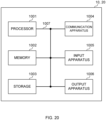
- FIG. 20 is a diagram to show an example of a hardware structure of the base station and the user terminal according to one embodiment.
- the above-described base station 10 and user terminal 20 may each be formed as a computer apparatus that includes a processor 1001, a memory 1002, a storage 1003, a communication apparatus 1004, an input apparatus 1005, an output apparatus 1006, a bus 1007, and so on.
- the words such as an apparatus, a circuit, a device, a section, a unit, and so on can be interchangeably interpreted.
- the hardware structure of the base station 10 and the user terminal 20 may be configured to include one or more of apparatuses shown in the drawings, or may be configured not to include part of apparatuses.
- processor 1001 may be implemented with one or more chips.
- Each function of the base station 10 and the user terminals 20 is implemented, for example, by allowing given software (programs) to be read on hardware such as the processor 1001 and the memory 1002, and by allowing the processor 1001 to perform calculations to control communication via the communication apparatus 1004 and control at least one of reading and writing of data in the memory 1002 and the storage 1003.
- software programs
- the processor 1001 to perform calculations to control communication via the communication apparatus 1004 and control at least one of reading and writing of data in the memory 1002 and the storage 1003.
- the processor 1001 controls the whole computer by, for example, running an operating system.
- the processor 1001 may be configured with a central processing unit (CPU), which includes interfaces with peripheral apparatus, control apparatus, computing apparatus, a register, and so on.
- CPU central processing unit
- control section 110 210
- transmitting/receiving section 120 220
- so on may be implemented by the processor 1001.
- the processor 1001 reads programs (program codes), software modules, data, and so on from at least one of the storage 1003 and the communication apparatus 1004, into the memory 1002, and executes various processes according to these.
- programs programs to allow computers to execute at least part of the operations of the above-described embodiments are used.
- the control section 110 (210) may be implemented by control programs that are stored in the memory 1002 and that operate on the processor 1001, and other functional blocks may be implemented likewise.
- the memory 1002 is a computer-readable recording medium, and may be constituted with, for example, at least one of a Read Only Memory (ROM), an Erasable Programmable ROM (EPROM), an Electrically EPROM (EEPROM), a Random Access Memory (RAM), and other appropriate storage media.
- ROM Read Only Memory
- EPROM Erasable Programmable ROM
- EEPROM Electrically EPROM
- RAM Random Access Memory
- the memory 1002 may be referred to as a "register,” a "cache,” a “main memory (primary storage apparatus)” and so on.
- the memory 1002 can store executable programs (program codes), software modules, and the like for implementing the radio communication method according to one embodiment of the present disclosure.
- the storage 1003 is a computer-readable recording medium, and may be constituted with, for example, at least one of a flexible disk, a floppy (registered trademark) disk, a magneto-optical disk (for example, a compact disc (Compact Disc ROM (CD-ROM) and so on), a digital versatile disc, a Blu-ray (registered trademark) disk), a removable disk, a hard disk drive, a smart card, a flash memory device (for example, a card, a stick, and a key drive), a magnetic stripe, a database, a server, and other appropriate storage media.
- the storage 1003 may be referred to as "secondary storage apparatus.”
- the communication apparatus 1004 is hardware (transmitting/receiving device) for allowing inter-computer communication via at least one of wired and wireless networks, and may be referred to as, for example, a "network device,” a “network controller,” a “network card,” a “communication module,” and so on.
- the communication apparatus 1004 may be configured to include a high frequency switch, a duplexer, a filter, a frequency synthesizer, and so on in order to realize, for example, at least one of frequency division duplex (FDD) and time division duplex (TDD).
- FDD frequency division duplex
- TDD time division duplex
- the above-described transmitting/receiving section 120 (220), the transmitting/receiving antennas 130 (230), and so on may be implemented by the communication apparatus 1004.
- the transmitting section 120a (220a) and the receiving section 120b (220b) can be implemented while being separated physically or logically.
- the input apparatus 1005 is an input device that receives input from the outside (for example, a keyboard, a mouse, a microphone, a switch, a button, a sensor, and so on).
- the output apparatus 1006 is an output device that allows sending output to the outside (for example, a display, a speaker, a Light Emitting Diode (LED) lamp, and so on). Note that the input apparatus 1005 and the output apparatus 1006 may be provided in an integrated structure (for example, a touch panel).
- bus 1007 for communicating information.
- the bus 1007 may be formed with a single bus, or may be formed with buses that vary between pieces of apparatus.
- the base station 10 and the user terminals 20 may be structured to include hardware such as a microprocessor, a digital signal processor (DSP), an Application Specific Integrated Circuit (ASIC), a Programmable Logic Device (PLD), a Field Programmable Gate Array (FPGA), and so on, and part or all of the functional blocks may be implemented by the hardware.
- the processor 1001 may be implemented with at least one of these pieces of hardware.
- a “channel,” a “symbol,” and a “signal” may be interchangeably interpreted.
- “signals” may be “messages.”
- a reference signal may be abbreviated as an “RS,” and may be referred to as a “pilot,” a “pilot signal,” and so on, depending on which standard applies.
- a “component carrier (CC)” may be referred to as a "cell,” a “frequency carrier,” a “carrier frequency” and so on.
- a radio frame may be constituted of one or a plurality of periods (frames) in the time domain.
- Each of one or a plurality of periods (frames) constituting a radio frame may be referred to as a "subframe.”
- a subframe may be constituted of one or a plurality of slots in the time domain.
- a subframe may be a fixed time length (for example, 1 ms) independent of numerology.
- numerology may be a communication parameter applied to at least one of transmission and reception of a given signal or channel.
- numerology may indicate at least one of a subcarrier spacing (SCS), a bandwidth, a symbol length, a cyclic prefix length, a transmission time interval (TTI), the number of symbols per TTI, a radio frame structure, a particular filter processing performed by a transceiver in the frequency domain, a particular windowing processing performed by a transceiver in the time domain, and so on.
- SCS subcarrier spacing
- TTI transmission time interval
- a slot may be constituted of one or a plurality of symbols in the time domain (Orthogonal Frequency Division Multiplexing (OFDM) symbols, Single Carrier Frequency Division Multiple Access (SC-FDMA) symbols, and so on). Furthermore, a slot may be a time unit based on numerology.
- OFDM Orthogonal Frequency Division Multiplexing
- SC-FDMA Single Carrier Frequency Division Multiple Access
- a slot may include a plurality of mini-slots. Each mini-slot may be constituted of one or a plurality of symbols in the time domain. A mini-slot may be referred to as a "sub-slot.” A mini-slot may be constituted of symbols less than the number of slots.
- a PDSCH (or PUSCH) transmitted in a time unit larger than a mini-slot may be referred to as "PDSCH (PUSCH) mapping type A.”
- a PDSCH (or PUSCH) transmitted using a mini-slot may be referred to as "PDSCH (PUSCH) mapping type B.”
- a radio frame, a subframe, a slot, a mini-slot, and a symbol all express time units in signal communication.
- a radio frame, a subframe, a slot, a mini-slot, and a symbol may each be called by other applicable terms.
- time units such as a frame, a subframe, a slot, mini-slot, and a symbol in the present disclosure may be interchangeably interpreted.
- one subframe may be referred to as a "TTI”
- a plurality of consecutive subframes may be referred to as a "TTI”
- one slot or one mini-slot may be referred to as a "TTI.” That is, at least one of a subframe and a TTI may be a subframe (1 ms) in existing LTE, may be a shorter period than 1 ms (for example, 1 to 13 symbols), or may be a longer period than 1 ms.
- a unit expressing TTI may be referred to as a "slot,” a "mini-slot,” and so on instead of a "subframe.”
- a TTI refers to the minimum time unit of scheduling in radio communication, for example.
- a base station schedules the allocation of radio resources (such as a frequency bandwidth and transmit power that are available for each user terminal) for the user terminal in TTI units.
- radio resources such as a frequency bandwidth and transmit power that are available for each user terminal
- TTIs may be transmission time units for channel-encoded data packets (transport blocks), code blocks, or codewords, or may be the unit of processing in scheduling, link adaptation, and so on. Note that, when TTIs are given, the time interval (for example, the number of symbols) to which transport blocks, code blocks, codewords, or the like are actually mapped may be shorter than the TTIs.
- one or more TTIs may be the minimum time unit of scheduling. Furthermore, the number of slots (the number of mini-slots) constituting the minimum time unit of the scheduling may be controlled.
- a TTI having a time length of 1 ms may be referred to as a "normal TTI” (TTI in 3GPP Rel. 8 to Rel. 12), a "long TTI,” a "normal subframe,” a “long subframe,” a “slot” and so on.
- a TTI that is shorter than a normal TTI may be referred to as a "shortened TTI,” a “short TTI,” a “partial or fractional TTI,” a "shortened subframe,” a “short subframe,” a “mini-slot,” a "sub-slot,” a “slot” and so on.
- a long TTI (for example, a normal TTI, a subframe, and so on) may be interpreted as a TTI having a time length exceeding 1 ms
- a short TTI (for example, a shortened TTI and so on) may be interpreted as a TTI having a TTI length shorter than the TTI length of a long TTI and equal to or longer than 1 ms.
- a resource block is the unit of resource allocation in the time domain and the frequency domain, and may include one or a plurality of consecutive subcarriers in the frequency domain.
- the number of subcarriers included in an RB may be the same regardless of numerology, and, for example, may be 12.
- the number of subcarriers included in an RB may be determined based on numerology.
- an RB may include one or a plurality of symbols in the time domain, and may be one slot, one mini-slot, one subframe, or one TTI in length.
- One TTI, one subframe, and so on each may be constituted of one or a plurality of resource blocks.
- RBs may be referred to as a "physical resource block (Physical RB (PRB)),” a “sub-carrier group (SCG),” a “resource element group (REG),”a “PRB pair,” an “RB pair” and so on.
- PRB Physical resource block
- SCG sub-carrier group
- REG resource element group
- a resource block may be constituted of one or a plurality of resource elements (REs).
- REs resource elements
- one RE may correspond to a radio resource field of one subcarrier and one symbol.
- a bandwidth part (which may be referred to as a "fractional bandwidth,” and so on) may represent a subset of contiguous common resource blocks (common RBs) for given numerology in a given carrier.
- common RB may be specified by an index of the RB based on the common reference point of the carrier.
- a PRB may be defined by a given BWP and may be numbered in the BWP.
- the BWP may include a UL BWP (BWP for the UL) and a DL BWP (BWP for the DL).
- BWP for the UL
- BWP for the DL DL
- One or a plurality of BWPs may be configured in one carrier for a UE.
- At least one of configured BWPs may be active, and a UE does not need to assume to transmit/receive a given signal/channel outside active BWPs.
- a "cell,” a “carrier,” and so on in the present disclosure may be interpreted as a "BWP”.
- radio frames, subframes, slots, mini-slots, symbols, and so on are merely examples.
- structures such as the number of subframes included in a radio frame, the number of slots per subframe or radio frame, the number of mini-slots included in a slot, the numbers of symbols and RBs included in a slot or a mini-slot, the number of subcarriers included in an RB, the number of symbols in a TTI, the symbol length, the cyclic prefix (CP) length, and so on can be variously changed.
- CP cyclic prefix
- radio resources may be specified by given indices.
- the information, signals, and so on described in the present disclosure may be represented by using any of a variety of different technologies.
- data, instructions, commands, information, signals, bits, symbols, chips, and so on may be represented by voltages, currents, electromagnetic waves, magnetic fields or particles, optical fields or photons, or any combination of these.
- information, signals, and so on can be output in at least one of from higher layers to lower layers and from lower layers to higher layers.
- Information, signals, and so on may be input/output via a plurality of network nodes.
- the information, signals, and so on that are input and/or output may be stored in a specific location (for example, a memory) or may be managed by using a management table.
- the information, signals, and so on to be input and/or output can be overwritten, updated, or appended.
- the information, signals, and so on that are output may be deleted.
- the information, signals, and so on that are input may be transmitted to another apparatus.
- reporting of information is by no means limited to the aspects/embodiments described in the present disclosure, and other methods may be used as well.
- reporting of information in the present disclosure may be implemented by using physical layer signaling (for example, downlink control information (DCI), uplink control information (UCI), higher layer signaling (for example, Radio Resource Control (RRC) signaling, broadcast information (master information block (MIB), system information blocks (SIBs), and so on), Medium Access Control (MAC) signaling and so on), and other signals or combinations of these.
- DCI downlink control information
- UCI uplink control information
- RRC Radio Resource Control
- MIB master information block
- SIBs system information blocks
- MAC Medium Access Control
- RRC signaling may be referred to as an "RRC message,” and can be, for example, an RRC connection setup message, an RRC connection reconfiguration message, and so on.
- MAC signaling may be reported using, for example, MAC control elements (MAC CEs).
- reporting of given information does not necessarily have to be reported explicitly, and can be reported implicitly (by, for example, not reporting this given information or reporting another piece of information).
- Determinations may be made in values represented by one bit (0 or 1), may be made in Boolean values that represent true or false, or may be made by comparing numerical values (for example, comparison against a given value).
- Software whether referred to as “software,” “firmware,” “middleware,” “microcode,” or “hardware description language,” or called by other terms, should be interpreted broadly to mean instructions, instruction sets, code, code segments, program codes, programs, subprograms, software modules, applications, software applications, software packages, routines, subroutines, objects, executable files, execution threads, procedures, functions, and so on.
- software, commands, information, and so on may be transmitted and received via communication media.
- communication media For example, when software is transmitted from a website, a server, or other remote sources by using at least one of wired technologies (coaxial cables, optical fiber cables, twisted-pair cables, digital subscriber lines (DSL), and so on) and wireless technologies (infrared radiation, microwaves, and so on), at least one of these wired technologies and wireless technologies are also included in the definition of communication media.
- wired technologies coaxial cables, optical fiber cables, twisted-pair cables, digital subscriber lines (DSL), and so on
- wireless technologies infrared radiation, microwaves, and so on
- the terms “system” and “network” used in the present disclosure can be used interchangeably.
- the “network” may mean an apparatus (for example, a base station) included in the network.
- precoding a "precoder,” a “weight (precoding weight),” “quasi-co-location (QCL),” a “Transmission Configuration Indication state (TCI state),” a "spatial relation,” a “spatial domain filter,” a “transmit power,” “phase rotation,” an "antenna port,” an “antenna port group,” a “layer,” “the number of layers,” a “rank,” a “resource,” a “resource set,” a “resource group,” a “beam,” a “beam width,” a “beam angular degree,” an “antenna,” an “antenna element,” a “panel,” and so on can be used interchangeably.
- a “base station (BS),” a “radio base station,” a “fixed station,” a “NodeB,” an “eNB (eNodeB),” a “gNB (gNodeB),” an “access point,” a “transmission point (TP),” a “reception point (RP),” a “transmission/reception point (TRP),” a “panel,” a “cell,” a “sector,” a “cell group,” a “carrier,” a “component carrier,” and so on can be used interchangeably.
- the base station may be referred to as the terms such as a "macro cell,” a small cell,” a “femto cell,” a “pico cell,” and so on.
- a base station can accommodate one or a plurality of (for example, three) cells.
- the entire coverage area of the base station can be partitioned into multiple smaller areas, and each smaller area can provide communication services through base station subsystems (for example, indoor small base stations (Remote Radio Heads (RRHs))).
- RRHs Remote Radio Heads
- the term "cell” or “sector” refers to part of or the entire coverage area of at least one of a base station and a base station subsystem that provides communication services within this coverage.
- MS mobile station
- UE user equipment
- terminal terminal
- a mobile station may be referred to as a "subscriber station,” “mobile unit,” “subscriber unit,” “wireless unit,” “remote unit,” “mobile device,” “wireless device,” “wireless communication device,” “remote device,” “mobile subscriber station,” “access terminal,” “mobile terminal,” “wireless terminal,” “remote terminal,” “handset,” “user agent,” “mobile client,” “client,” or some other appropriate terms in some cases.
- At least one of a base station and a mobile station may be referred to as a "transmitting apparatus," a “receiving apparatus,” a “radio communication apparatus,” and so on.
- a base station and a mobile station may be device mounted on a moving object or a moving object itself, and so on.
- the moving object may be a vehicle (for example, a car, an airplane, and the like), may be a moving object which moves unmanned (for example, a drone, an automatic operation car, and the like), or may be a robot (a manned type or unmanned type).
- at least one of a base station and a mobile station also includes an apparatus which does not necessarily move during communication operation.
- at least one of a base station and a mobile station may be an Internet of Things (IoT) device such as a sensor, and the like.
- IoT Internet of Things
- the base station in the present disclosure may be interpreted as a user terminal.
- each aspect/embodiment of the present disclosure may be applied to the structure that replaces a communication between a base station and a user terminal with a communication between a plurality of user terminals (for example, which may be referred to as "Device-to-Device (D2D)," “Vehicle-to-Everything (V2X),” and the like).
- user terminals 20 may have the functions of the base stations 10 described above.
- the words "uplink” and “downlink” may be interpreted as the words corresponding to the terminal-to-terminal communication (for example, "side”).
- an uplink channel, a downlink channel and so on may be interpreted as a side channel.
- the user terminal in the present disclosure may be interpreted as base station.
- the base station 10 may have the functions of the user terminal 20 described above.
- Actions which have been described in the present disclosure to be performed by a base station may, in some cases, be performed by upper nodes.
- a network including one or a plurality of network nodes with base stations it is clear that various operations that are performed to communicate with terminals can be performed by base stations, one or more network nodes (for example, Mobility Management Entities (MMEs), Serving-Gateways (S-GWs), and so on may be possible, but these are not limiting) other than base stations, or combinations of these.
- MMEs Mobility Management Entities
- S-GWs Serving-Gateways
- aspects/embodiments illustrated in the present disclosure may be used individually or in combinations, which may be switched depending on the mode of implementation.
- the order of processes, sequences, flowcharts, and so on that have been used to describe the aspects/embodiments in the present disclosure may be re-ordered as long as inconsistencies do not arise.
- various methods have been illustrated in the present disclosure with various components of steps in exemplary orders, the specific orders that are illustrated herein are by no means limiting.
- LTE Long Term Evolution
- LTE-A LTE-Advanced
- LTE-B LTE-Beyond
- SUPER 3G IMT-Advanced
- 4th generation mobile communication system 4th generation mobile communication system
- 5G 5th generation mobile communication system
- 6G 6th generation mobile communication system
- xG xG (where x is, for example, an integer or a decimal)
- Future Radio Access FAA
- New-Radio Access Technology RAT
- NR New Radio
- NX New radio access
- FX Future generation radio access
- GSM Global System for Mobile communications
- CDMA 2000 Ultra Mobile Broadband
- UMB Ultra Mobile Broadband
- IEEE 802.11 Wi-Fi (registered trademark)
- IEEE 802.16 WiMAX (registered trademark)
- IEEE 802.20 Ultra-WideBand (UWB), Bluetooth (registered trademark), systems that use other adequate radio communication methods and next-generation systems that are enhanced based
- phrase “based on” (or “on the basis of”) as used in the present disclosure does not mean “based only on” (or “only on the basis of”), unless otherwise specified.
- the phrase “based on” (or “on the basis of”) means both “based only on” and “based at least on” (“only on the basis of” and “at least on the basis of”).
- references to elements with designations such as “first,” “second,” and so on as used in the present disclosure does not generally limit the quantity or order of these elements. These designations may be used in the present disclosure only for convenience, as a method for distinguishing between two or more elements. Thus, reference to the first and second elements does not imply that only two elements may be employed, or that the first element must precede the second element in some way.
- judging (determining) may encompass a wide variety of actions. For example, “judging (determining)” may be interpreted to mean making “judgments (determinations)” about judging, calculating, computing, processing, deriving, investigating, looking up, search and inquiry (for example, searching a table, a database, or some other data structures), ascertaining, and so on.
- judging (determining) may be interpreted to mean making “judgments (determinations)” about receiving (for example, receiving information), transmitting (for example, transmitting information), input, output, accessing (for example, accessing data in a memory), and so on.
- judging (determining) as used herein may be interpreted to mean making “judgments (determinations)” about resolving, selecting, choosing, establishing, comparing, and so on. In other words, “judging (determining)” may be interpreted to mean making “judgments (determinations)” about some action.
- judging (determining) may be interpreted as “assuming,” “expecting,” “considering,” and the like.
- the maximum transmit power may mean a maximum value of the transmit power, may mean the nominal maximum transmit power (the nominal UE maximum transmit power), or may mean the rated maximum transmit power (the rated UE maximum transmit power).
- connection and “coupled,” or any variation of these terms as used in the present disclosure mean all direct or indirect connections or coupling between two or more elements, and may include the presence of one or more intermediate elements between two elements that are “connected” or “coupled” to each other.
- the coupling or connection between the elements may be physical, logical, or a combination thereof. For example, “connection” may be interpreted as "access.”
- the two elements when two elements are connected, the two elements may be considered “connected” or “coupled” to each other by using one or more electrical wires, cables and printed electrical connections, and, as some non-limiting and non-inclusive examples, by using electromagnetic energy having wavelengths in radio frequency regions, microwave regions, (both visible and invisible) optical regions, or the like.
- the phrase "A and B are different” may mean that "A and B are different from each other.” Note that the phrase may mean that "A and B is each different from C.”
- the terms “separate,” “be coupled,” and so on may be interpreted similarly to “different.”
- the present disclosure may include that a noun after these articles is in a plural form.
Landscapes
- Engineering & Computer Science (AREA)
- Signal Processing (AREA)
- Computer Networks & Wireless Communication (AREA)
- Mobile Radio Communication Systems (AREA)
Applications Claiming Priority (1)
| Application Number | Priority Date | Filing Date | Title |
|---|---|---|---|
| PCT/JP2020/029473 WO2022024358A1 (ja) | 2020-07-31 | 2020-07-31 | 端末、無線通信方法及び基地局 |
Publications (2)
| Publication Number | Publication Date |
|---|---|
| EP4192148A1 true EP4192148A1 (de) | 2023-06-07 |
| EP4192148A4 EP4192148A4 (de) | 2024-05-01 |
Family
ID=80035330
Family Applications (1)
| Application Number | Title | Priority Date | Filing Date |
|---|---|---|---|
| EP20946934.5A Pending EP4192148A4 (de) | 2020-07-31 | 2020-07-31 | Endgerät, funkkommunikationsverfahren und basisstation |
Country Status (4)
| Country | Link |
|---|---|
| EP (1) | EP4192148A4 (de) |
| JP (1) | JPWO2022024358A1 (de) |
| CN (1) | CN116235589A (de) |
| WO (1) | WO2022024358A1 (de) |
Families Citing this family (2)
| Publication number | Priority date | Publication date | Assignee | Title |
|---|---|---|---|---|
| CN116865918A (zh) * | 2022-03-21 | 2023-10-10 | 上海朗帛通信技术有限公司 | 一种被用于无线通信的节点中的方法和装置 |
| WO2024029039A1 (ja) * | 2022-08-04 | 2024-02-08 | 株式会社Nttドコモ | 端末、無線通信方法及び基地局 |
Family Cites Families (5)
| Publication number | Priority date | Publication date | Assignee | Title |
|---|---|---|---|---|
| WO2019244222A1 (ja) * | 2018-06-18 | 2019-12-26 | 株式会社Nttドコモ | ユーザ端末及び無線通信方法 |
| JP7171719B2 (ja) * | 2018-06-18 | 2022-11-15 | 株式会社Nttドコモ | 端末、無線通信方法、基地局及びシステム |
| US11601824B2 (en) * | 2018-08-10 | 2023-03-07 | Apple Inc. | TCI and QCL configuration in 5G networks |
| KR102700669B1 (ko) * | 2018-08-16 | 2024-08-30 | 삼성전자주식회사 | 무선통신 시스템에서 데이터를 송수신하는 방법 및 장치 |
| CN111278092B (zh) * | 2019-04-26 | 2021-06-08 | 维沃移动通信有限公司 | 一种信道监听方法、终端及网络设备 |
-
2020
- 2020-07-31 EP EP20946934.5A patent/EP4192148A4/de active Pending
- 2020-07-31 WO PCT/JP2020/029473 patent/WO2022024358A1/ja active Application Filing
- 2020-07-31 JP JP2022539954A patent/JPWO2022024358A1/ja active Pending
- 2020-07-31 CN CN202080105727.XA patent/CN116235589A/zh active Pending
Also Published As
| Publication number | Publication date |
|---|---|
| WO2022024358A1 (ja) | 2022-02-03 |
| JPWO2022024358A1 (de) | 2022-02-03 |
| CN116235589A (zh) | 2023-06-06 |
| EP4192148A4 (de) | 2024-05-01 |
Similar Documents
| Publication | Publication Date | Title |
|---|---|---|
| EP4013165A1 (de) | Endgerät und drahtloskommunikationsverfahren | |
| EP3968534A1 (de) | Benutzerendgerät und drahtloskommunikationsverfahren | |
| EP3955622A1 (de) | Benutzerendgerät und drahtloskommunikationsverfahren | |
| EP4192069A1 (de) | Endgerät, drahtloskommunikationsverfahren und basisstation | |
| EP3944688A1 (de) | Benutzerendgerät und drahtloskommunikationsverfahren | |
| EP4213585A1 (de) | Endgerät, drahtloskommunikationsverfahren und basisstation | |
| EP4224903A1 (de) | Endgerät, funkkommunikationsverfahren und basisstation | |
| EP4325923A1 (de) | Endgerät, drahtloskommunikationsverfahren und basisstation | |
| US20230308249A1 (en) | Terminal, radio communication method, and base station | |
| EP3952513A1 (de) | Benutzerendgerät und drahtloskommunikationsverfahren | |
| EP3972364A1 (de) | Endgerät und drahtloskommunikationsverfahren | |
| EP4287737A1 (de) | Endgerät, drahtloskommunikationsverfahren und basisstation | |
| EP4247038A1 (de) | Endgerät, drahtloskommunikationsverfahren und basisstation | |
| US20230299901A1 (en) | Terminal, radio communication method, and base station | |
| US20240163956A1 (en) | Terminal, radio communication method, and base station | |
| US20240129933A1 (en) | Terminal, radio communication method, and base station | |
| EP4192148A1 (de) | Endgerät, funkkommunikationsverfahren und basisstation | |
| EP4280652A1 (de) | Endgerät, funkkommunikationsverfahren und basisstation | |
| US20230276435A1 (en) | Terminal, radio communication method, and base station | |
| EP4132215A1 (de) | Endgerät, drahtloskommunikationsverfahren und basisstation | |
| EP4040882A1 (de) | Endgerät und drahtloskommunikationsverfahren | |
| EP4040881A1 (de) | Endgerät und drahtloskommunikationsverfahren | |
| EP4002712A1 (de) | Endgerät und drahtloskommunikationsverfahren | |
| EP3972336A1 (de) | Benutzerendgerät und drahtloskommunikationsverfahren | |
| EP4304220A1 (de) | Endgerät, drahtloskommunikationsverfahren und basisstation |
Legal Events
| Date | Code | Title | Description |
|---|---|---|---|
| STAA | Information on the status of an ep patent application or granted ep patent |
Free format text: STATUS: THE INTERNATIONAL PUBLICATION HAS BEEN MADE |
|
| PUAI | Public reference made under article 153(3) epc to a published international application that has entered the european phase |
Free format text: ORIGINAL CODE: 0009012 |
|
| STAA | Information on the status of an ep patent application or granted ep patent |
Free format text: STATUS: REQUEST FOR EXAMINATION WAS MADE |
|
| 17P | Request for examination filed |
Effective date: 20230214 |
|
| AK | Designated contracting states |
Kind code of ref document: A1 Designated state(s): AL AT BE BG CH CY CZ DE DK EE ES FI FR GB GR HR HU IE IS IT LI LT LU LV MC MK MT NL NO PL PT RO RS SE SI SK SM TR |
|
| DAV | Request for validation of the european patent (deleted) | ||
| DAX | Request for extension of the european patent (deleted) | ||
| A4 | Supplementary search report drawn up and despatched |
Effective date: 20240405 |
|
| RIC1 | Information provided on ipc code assigned before grant |
Ipc: H04L 5/00 20060101ALI20240328BHEP Ipc: H04W 72/04 20090101AFI20240328BHEP |