EP4192000A1 - Verfahren und system zur zonenweisen adaptiven beleuchtung von objekten - Google Patents
Verfahren und system zur zonenweisen adaptiven beleuchtung von objekten Download PDFInfo
- Publication number
- EP4192000A1 EP4192000A1 EP22205968.5A EP22205968A EP4192000A1 EP 4192000 A1 EP4192000 A1 EP 4192000A1 EP 22205968 A EP22205968 A EP 22205968A EP 4192000 A1 EP4192000 A1 EP 4192000A1
- Authority
- EP
- European Patent Office
- Prior art keywords
- illuminators
- image
- illuminance
- intensity
- threshold
- Prior art date
- Legal status (The legal status is an assumption and is not a legal conclusion. Google has not performed a legal analysis and makes no representation as to the accuracy of the status listed.)
- Granted
Links
Images

Classifications
-
- H—ELECTRICITY
- H04—ELECTRIC COMMUNICATION TECHNIQUE
- H04N—PICTORIAL COMMUNICATION, e.g. TELEVISION
- H04N23/00—Cameras or camera modules comprising electronic image sensors; Control thereof
- H04N23/50—Constructional details
- H04N23/555—Constructional details for picking-up images in sites, inaccessible due to their dimensions or hazardous conditions, e.g. endoscopes or borescopes
-
- G—PHYSICS
- G06—COMPUTING OR CALCULATING; COUNTING
- G06T—IMAGE DATA PROCESSING OR GENERATION, IN GENERAL
- G06T7/00—Image analysis
- G06T7/0002—Inspection of images, e.g. flaw detection
-
- G—PHYSICS
- G06—COMPUTING OR CALCULATING; COUNTING
- G06V—IMAGE OR VIDEO RECOGNITION OR UNDERSTANDING
- G06V10/00—Arrangements for image or video recognition or understanding
- G06V10/10—Image acquisition
- G06V10/12—Details of acquisition arrangements; Constructional details thereof
- G06V10/14—Optical characteristics of the device performing the acquisition or on the illumination arrangements
- G06V10/141—Control of illumination
-
- G—PHYSICS
- G06—COMPUTING OR CALCULATING; COUNTING
- G06V—IMAGE OR VIDEO RECOGNITION OR UNDERSTANDING
- G06V10/00—Arrangements for image or video recognition or understanding
- G06V10/40—Extraction of image or video features
- G06V10/44—Local feature extraction by analysis of parts of the pattern, e.g. by detecting edges, contours, loops, corners, strokes or intersections; Connectivity analysis, e.g. of connected components
- G06V10/443—Local feature extraction by analysis of parts of the pattern, e.g. by detecting edges, contours, loops, corners, strokes or intersections; Connectivity analysis, e.g. of connected components by matching or filtering
-
- H—ELECTRICITY
- H04—ELECTRIC COMMUNICATION TECHNIQUE
- H04N—PICTORIAL COMMUNICATION, e.g. TELEVISION
- H04N23/00—Cameras or camera modules comprising electronic image sensors; Control thereof
- H04N23/56—Cameras or camera modules comprising electronic image sensors; Control thereof provided with illuminating means
-
- H—ELECTRICITY
- H04—ELECTRIC COMMUNICATION TECHNIQUE
- H04N—PICTORIAL COMMUNICATION, e.g. TELEVISION
- H04N23/00—Cameras or camera modules comprising electronic image sensors; Control thereof
- H04N23/60—Control of cameras or camera modules
- H04N23/61—Control of cameras or camera modules based on recognised objects
-
- H—ELECTRICITY
- H04—ELECTRIC COMMUNICATION TECHNIQUE
- H04N—PICTORIAL COMMUNICATION, e.g. TELEVISION
- H04N23/00—Cameras or camera modules comprising electronic image sensors; Control thereof
- H04N23/70—Circuitry for compensating brightness variation in the scene
- H04N23/71—Circuitry for evaluating the brightness variation
-
- H—ELECTRICITY
- H04—ELECTRIC COMMUNICATION TECHNIQUE
- H04N—PICTORIAL COMMUNICATION, e.g. TELEVISION
- H04N23/00—Cameras or camera modules comprising electronic image sensors; Control thereof
- H04N23/70—Circuitry for compensating brightness variation in the scene
- H04N23/74—Circuitry for compensating brightness variation in the scene by influencing the scene brightness using illuminating means
-
- H—ELECTRICITY
- H04—ELECTRIC COMMUNICATION TECHNIQUE
- H04N—PICTORIAL COMMUNICATION, e.g. TELEVISION
- H04N5/00—Details of television systems
- H04N5/222—Studio circuitry; Studio devices; Studio equipment
- H04N5/262—Studio circuits, e.g. for mixing, switching-over, change of character of image, other special effects ; Cameras specially adapted for the electronic generation of special effects
- H04N5/272—Means for inserting a foreground image in a background image, i.e. inlay, outlay
-
- G—PHYSICS
- G06—COMPUTING OR CALCULATING; COUNTING
- G06T—IMAGE DATA PROCESSING OR GENERATION, IN GENERAL
- G06T2207/00—Indexing scheme for image analysis or image enhancement
- G06T2207/10—Image acquisition modality
- G06T2207/10141—Special mode during image acquisition
- G06T2207/10152—Varying illumination
-
- G—PHYSICS
- G06—COMPUTING OR CALCULATING; COUNTING
- G06T—IMAGE DATA PROCESSING OR GENERATION, IN GENERAL
- G06T2207/00—Indexing scheme for image analysis or image enhancement
- G06T2207/20—Special algorithmic details
- G06T2207/20021—Dividing image into blocks, subimages or windows
-
- G—PHYSICS
- G06—COMPUTING OR CALCULATING; COUNTING
- G06T—IMAGE DATA PROCESSING OR GENERATION, IN GENERAL
- G06T2207/00—Indexing scheme for image analysis or image enhancement
- G06T2207/20—Special algorithmic details
- G06T2207/20081—Training; Learning
-
- G—PHYSICS
- G06—COMPUTING OR CALCULATING; COUNTING
- G06T—IMAGE DATA PROCESSING OR GENERATION, IN GENERAL
- G06T2207/00—Indexing scheme for image analysis or image enhancement
- G06T2207/20—Special algorithmic details
- G06T2207/20084—Artificial neural networks [ANN]
-
- G—PHYSICS
- G06—COMPUTING OR CALCULATING; COUNTING
- G06T—IMAGE DATA PROCESSING OR GENERATION, IN GENERAL
- G06T2207/00—Indexing scheme for image analysis or image enhancement
- G06T2207/20—Special algorithmic details
- G06T2207/20112—Image segmentation details
Definitions
- the disclosure herein generally relates to illumination of objects, and, more particularly, to a method and system for adaptive illumination of objects.
- illumination is a challenge in many scenarios.
- An example scenario is fragmentation analysis carried out in underground mines.
- the underground mines pose a challenge to deployment of vision-based fragmentation analysis systems as it is a poorly-lit and is a constrained environment.
- state of the art computer vision solutions for fragmentation analysis have not been able to address the case of precise segmentation of overlapping ore particles, and with poor illumination and poor quality of acquired images, this task becomes even more challenging.
- a processor implemented method for adaptive illumination of an object is provided.
- initially at least one image of an object is obtained via one or more hardware processors, wherein the at least one image is captured when the object is illuminated by a plurality of Infrared (IR) illuminators from an IR illuminator array.
- the at least one image is then pre-processed via the one or more hardware processors, wherein the pre-processing comprises of a) adjusting contrast, and b) performing normalization, of one or more frames captured in the at least one image.
- IR Infrared
- a semantic segmentation of pre-processed at least one image is performed via the one or more hardware processors, to extract foreground (FG) data and background (BG) data of the at least one image.
- a binary semantic mask of the at least one image is generated, via the one or more hardware processors, wherein the binary semantic mask comprises information on the extracted BG data and the FG data of the at least one image.
- an Edge based Structural Similarity Index Metric (ESSIM) matrix is constructed from the binary semantic mask, via the one or more hardware processors, wherein the ESSIM indicates a measured illuminance of each of a plurality of zones in at least one Region of Interest (RoI) of the object, in terms of a) luminance, b) contrast, and c) one or more edge comparison functions. Further, it is determined via the one or more hardware processors, whether the measured illuminance of each of the plurality of zones of the object at least matches a threshold of illuminance. Then intensity of one or more of the plurality of illuminators is varied to improve the illuminance of each of the plurality of zones for which the measured illuminance is below the threshold of illuminance, to at least match the threshold of illuminance.
- ESSIM Edge based Structural Similarity Index Metric
- varying the intensity of one or more of the plurality of illuminators involves the following steps. Initially, one or more of the plurality of illuminators corresponding to each of the plurality of zones for which the measured illuminance is below the threshold of illuminance are identified, based on a mapping of each of the plurality of zones with the corresponding one or more illuminators. Further, extent to which the intensity of each of the identified one or more illuminators is required to be varied to improve the illumination in the corresponding zone to at least match the threshold of illuminance is determined.
- a control signal is generated to vary the intensity of the one or more of the plurality of illuminators, based on the determined extent to which the intensity of each of the identified one or more illuminators is required to be varied. Then using the control signal, the intensity of each of the identified one or more illuminators is varied.
- a system for adaptive illumination of an object includes one or more hardware processors, a communication interface, and a memory storing a plurality of instructions.
- the plurality of instructions when executed, cause the one or more hardware processors to perform the following steps for the targeted illumination.
- at least one image of an object is obtained via one or more hardware processors, wherein the at least one image is captured when the object is illuminated by a plurality of Infrared (IR) illuminators from an IR illuminator array.
- IR Infrared
- the at least one image is then pre-processed via the one or more hardware processors, wherein the pre-processing comprises of a) adjusting contrast, and b) performing normalization, of one or more frames captured in the at least one image.
- a semantic segmentation of pre-processed at least one image is performed via the one or more hardware processors, to extract foreground (FG) data and background (BG) data of the at least one image.
- a binary semantic mask of the at least one image is generated, via the one or more hardware processors, wherein the binary semantic mask comprises information on the extracted BG data and the FG data of the at least one image.
- an Edge based Structural Similarity Index Metric (ESSIM) matrix is constructed from the binary semantic mask, via the one or more hardware processors, wherein the ESSIM indicates a measured illuminance of each of a plurality of zones in at least one Region of Interest (RoI) of the object, in terms of a) luminance, b) contrast, and c) one or more edge comparison functions. Further, it is determined via the one or more hardware processors, whether the measured illuminance of each of the plurality of zones of the object at least matches a threshold of illuminance. Then intensity of one or more of the plurality of illuminators is varied to improve the illuminance of each of the plurality of zones for which the measured illuminance is below the threshold of illuminance, to at least match the threshold of illuminance.
- ESSIM Edge based Structural Similarity Index Metric
- the one or more hardware processors in the system are configured to vary the intensity of one or more of the plurality of illuminators by executing the following steps. Initially, one or more of the plurality of illuminators corresponding to each of the plurality of zones for which the measured illuminance is below the threshold of illuminance are identified, based on a mapping of each of the plurality of zones with the corresponding one or more illuminators. Further, extent to which the intensity of each of the identified one or more illuminators is required to be varied to improve the illumination in the corresponding zone to at least match the threshold of illuminance is determined.
- a control signal is generated to vary the intensity of the one or more of the plurality of illuminators, based on the determined extent to which the intensity of each of the identified one or more illuminators is required to be varied. Then using the control signal, the intensity of each of the identified one or more illuminators is varied.
- a non-transitory computer readable medium for adaptive illumination of an object.
- the non-transitory computer readable medium includes a plurality of instructions, which when executed, cause the following steps. Initially at least one image of an object is obtained via one or more hardware processors, wherein the at least one image is captured when the object is illuminated by a plurality of Infrared (IR) illuminators from an IR illuminator array.
- IR Infrared
- the at least one image is then pre-processed via the one or more hardware processors, wherein the pre-processing comprises of a) adjusting contrast, and b) performing normalization, of one or more frames captured in the at least one image.
- a semantic segmentation of pre-processed at least one image is performed via the one or more hardware processors, to extract foreground (FG) data and background (BG) data of the at least one image.
- a binary semantic mask of the at least one image is generated, via the one or more hardware processors, wherein the binary semantic mask comprises information on the extracted BG data and the FG data of the at least one image.
- an Edge based Structural Similarity Index Metric (ESSIM) matrix is constructed from the binary semantic mask, via the one or more hardware processors, wherein the ESSIM indicates a measured illuminance of each of a plurality of zones in at least one Region of Interest (RoI) of the object, in terms of a) luminance, b) contrast, and c) one or more edge comparison functions. Further, it is determined via the one or more hardware processors, whether the measured illuminance of each of the plurality of zones of the object at least matches a threshold of illuminance. Then intensity of one or more of the plurality of illuminators is varied to improve the illuminance of each of the plurality of zones for which the measured illuminance is below the threshold of illuminance, to at least match the threshold of illuminance.
- ESSIM Edge based Structural Similarity Index Metric
- the non-transitory computer readable medium varies the intensity of one or more of the plurality of illuminators by executing the following steps. Initially, one or more of the plurality of illuminators corresponding to each of the plurality of zones for which the measured illuminance is below the threshold of illuminance are identified, based on a mapping of each of the plurality of zones with the corresponding one or more illuminators. Further, extent to which the intensity of each of the identified one or more illuminators is required to be varied to improve the illumination in the corresponding zone to at least match the threshold of illuminance is determined.
- a control signal is generated to vary the intensity of the one or more of the plurality of illuminators, based on the determined extent to which the intensity of each of the identified one or more illuminators is required to be varied. Then using the control signal, the intensity of each of the identified one or more illuminators is varied.
- IR Infrared
- a disadvantage of the state of the art illumination mechanisms is that they are static in the sense all the light sources operate at maximum power irrespective of the lighting conditions. For example, some sides/parts of the object may have been properly illuminated, and only the remaining sides/parts may have to be illuminated.
- all sides/parts may have to be illuminated, but again depending on how well different sides/parts are already illuminated, intensity of the light sources may be varied, improving power saving and efficiency.
- the static approach used by the state of the art systems fail to perform the adaptive control and illumination of the light sources, resulting in poor lighting, and in turn in poor quality images.
- the embodiments disclosed herein provide a method and system for adaptive illumination of objects.
- the system 100 determines, by processing one or more images of an object, whether all of a plurality of zones of the object are illuminated to at least meet a threshold of illuminance. If a measured illumination of any of the zones is below the threshold of illumination, then the system 100 selectively varies intensity of one or more illuminators from among a plurality of illuminators, to illuminate only the zones for which the measured illumination is below the threshold of illumination. The illumination of these zones is adjusted to at least match the illumination with the threshold of illumination.
- the adaptive illumination further helps in achieving targeted illumination i.e. only selected zones are highlighted, and by selectively varying intensity of the IR illuminators.
- FIG. 1 through FIG. 4B where similar reference characters denote corresponding features consistently throughout the figures, there are shown preferred embodiments and these embodiments are described in the context of the following exemplary system and/or method.
- FIG. 1 illustrates an exemplary system for adaptive illumination of an object, according to some embodiments of the present disclosure.
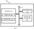
- the system 100 includes or is otherwise in communication with hardware processors 102, at least one memory such as a memory 104, and an Input /Output (I/O) interface 112.
- the hardware processors 102, memory 104, and the I/O interface 112 may be coupled by a system bus such as a system bus 108 or a similar mechanism.
- the hardware processors 102 can be one or more hardware processors.
- the I/O interface 112 may include a variety of software and hardware interfaces, for example, a web interface, a graphical user interface, and the like.
- the I/O interface 112 may include a variety of software and hardware interfaces, for example, interfaces for peripheral device(s), such as a keyboard, a mouse, an external memory, a printer and the like. Further, the I/O interface 112 may enable the system 100 to communicate with other devices, such as web servers, and external databases.
- the I/O interface 112 can facilitate multiple communications within a wide variety of networks and protocol types, including wired networks, for example, local area network (LAN), cable, etc., and wireless networks, such as Wireless LAN (WLAN), cellular, or satellite.
- the I/O interface 112 may include one or more ports for connecting several computing systems with one another or to another server computer.
- the I/O interface 112 may include one or more ports for connecting several devices to one another or to another server.
- the one or more hardware processors 102 may be implemented as one or more microprocessors, microcomputers, microcontrollers, digital signal processors, central processing units, node machines, logic circuitries, and/or any devices that manipulate signals based on operational instructions.
- the one or more hardware processors 102 is configured to fetch and execute computer-readable instructions stored in the memory 104.
- the memory 104 may include any computer-readable medium known in the art including, for example, volatile memory, such as static random access memory (SRAM) and dynamic random access memory (DRAM), and/or non-volatile memory, such as read only memory (ROM), erasable programmable ROM, flash memories, hard disks, optical disks, and magnetic tapes.
- volatile memory such as static random access memory (SRAM) and dynamic random access memory (DRAM)
- non-volatile memory such as read only memory (ROM), erasable programmable ROM, flash memories, hard disks, optical disks, and magnetic tapes.
- the memory 104 includes a plurality of modules 106.
- the memory 104 also includes a data repository (or repository) 110 for storing data processed, received, and generated by the plurality of modules 106.
- the plurality of modules 106 include programs or coded instructions that supplement applications or functions performed by the system 100 for the adaptive illumination of objects.
- the plurality of modules 106 can include routines, programs, objects, components, and data structures, which performs particular tasks or implement particular abstract data types.
- the plurality of modules 106 may also be used as, signal processor(s), node machine(s), logic circuitries, and/or any other device or component that manipulates signals based on operational instructions.
- the plurality of modules 106 can be used by hardware, by computer-readable instructions executed by the one or more hardware processors 102, or by a combination thereof.
- the plurality of modules 106 can include various sub-modules (not shown).
- the plurality of modules 106 may include computer-readable instructions that supplement applications or functions performed by the system 100 for the adaptive illumination of objects.
- the data repository (or repository) 110 may include a plurality of abstracted piece of code for refinement and data that is processed, received, or generated as a result of the execution of the plurality of modules in the module(s) 106.
- the data repository 110 is shown internal to the system 100, it will be noted that, in alternate embodiments, the data repository 110 can also be implemented external to the system 100, where the data repository 110 may be stored within a database (not shown in FIG. 1 ) communicatively coupled to the system 100.
- the data contained within such external database may be periodically updated. For example, new data may be added into the database (not shown in FIG. 1 ) and/or existing data may be modified and/or non-useful data may be deleted from the database (not shown in FIG. 1 ).
- the data may be stored in an external system, such as a Lightweight Directory Access Protocol (LDAP) directory and a Relational Database Management System (RDBMS).
- LDAP Lightweight Directory Access Protocol
- RDBMS Relational Database Management System
- FIG. 2 and FIG. 3 Steps involved in the process of adaptive illumination of objects, being performed by the system 100, are depicted in FIG. 2 and FIG. 3 .
- the steps in FIG. 2 and FIG. 3 are explained with reference to the components of the system 100 as depicted in FIG. 1 .
- FIGS. 2A and 2B (collectively referred to as FIG. 2 , and method 200) illustrate a flow diagram depicting steps involved in the process of adaptive illumination of the object, by the system of FIG. 1 , according to some embodiments of the present disclosure.
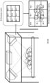
- an illumination setup (alternately referred to as "setup") which is used for illuminating objects.
- the setup as in FIGS. 4A and 4B is considered.
- an array of Infrared (IR) illuminators is used.
- the array of IR illuminators includes a plurality of IR illuminators/emitters (total 9 from IR 0 to IR 8 in this setup, as depicted in FIG. 4B ), such that the IR illuminators are positioned such that each of the IR illuminators Illuminate different zones of the object.
- zone in the context of the embodiments disclosed herein may refer to different parts/sides (for example, front, back, and so on) of the object.
- the object is placed on a conveyor belt which may or may not be moving while the one or more images of the object is being taken by an image capturing means i.e. the IR imager in this setup.
- the captured one or more images are then processed by the system 100 i.e. the edge computer in FIG. 4A .
- the system 100 i.e. the edge computer in FIG. 4A .
- implementation of the system 100 as the edge computer is only an example. In other modes of implementation, the system 100 may be outside the setup, locally or in a remote location or cloud.
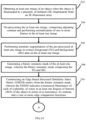
- the system 100 obtains the at least one image of the object, wherein the at least one image is captured when the object is illuminated by the IR illuminators.
- the IR illuminators may be operating at a uniform capacity.
- the illumination at different zones of the object may not be uniform due to various factors such as but not limited to presence of non-uniform external lighting.
- the at least one image is pre-processed by the system 100.
- Pre-processing the at least one image involves adjusting contrast and performing normalization of one or more frames in the at least one image.
- the system 100 performs the contrast adjustment based on a perceived contrast quality metric, which may contain a pre-configured value of contrast, and the contrast adjustment at this stage acts as a preliminary adjustment.
- Performing the normalization involves changing range of pixel intensity values by determining a normalized pixel intensity level for each of a plurality of pixels of the at least one image, to improve quality of the at least one image, for further processing.
- the system 100 performs a semantic segmentation of the pre-processed at least one image, and extracts foreground (FG) and background (BG) data from the at least one image.
- the system 100 may use a neural network which uses a data model generated using training data comprising a plurality of test images, and corresponding FG and BG data.
- any other suitable technique i.e. other than the neural network based approach may be used for segregating the FG and BG of the at least one image.
- the system 100 generates a binary mask of the at least one image.
- the binary mask includes information on the extracted FG and BG.
- the system 100 identifies one or more Region of Interest (RoI) with the FG, based on the data in the binary mask of the at least one image.
- the FG data in the binary mask forms the RoI.
- the system 100 performs a full scale segmentation of all objects in each of the ROIs in the FG of the at least one image. For example, if the at least one image is of a metal ore and when the application is fragmentation analysis, the full scale segmentation helps in identifying impurities such as rock particles in the metal ore.
- the system 100 may use an artificial neural network based approach for the full scale segmentation, using appropriate neural network technique such as but not limited to U-Net, RCNN, and deeplab.
- the data generated by the full scale segmentation may still contain overlapping un-segmented regions.
- the system 100 may be configured to use an additional regional proposal network to determine the bounding boxes and thus assist in segmenting out overlapping/overcrowded regions by intelligently eroding their boundaries. Output of the full scale segmentation may be then annotated with the boulders (anomaly in case of fragmentation analysis) and the output parameters like boulder count, mean particle size are evaluated.
- the system 100 constructs an Edge based Structural Similarity Index Metric (ESSIM) from the binary semantic mask, wherein the ESSIM indicates a measured illuminance of each of a plurality of zones in at least one Region of Interest (ROI) of the object in terms of a) luminance (L), b) contrast I, and c) one or more edge comparison functions I.
- ESSIM Edge based Structural Similarity Index Metric
- ESSIM x y L x y ⁇ . C x y ⁇ . E x y ⁇
- L the luminance comparison function
- C the contrast comparison function
- E the edge comparison function
- ⁇ , ⁇ and ⁇ constants pertaining to relative importance of each function.
- A, ⁇ and ⁇ can be taken as 1.
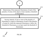
- the ESSIM converts input ROI into smaller blocks (of say 16x16) and estimates the edge direction histograms and edge comparison function based on a reference image. All the three parameters (L, C and E) are estimated individually and together they comprise the ESSIM, and the value of ESSIM in turn represents a measured illumination of each of the zones. In this case, the edge function of ESSIM is estimated to check whether the edges in the output mask meet the required threshold. As the ESSIM is estimated separately for each of the zones, at step 212, the system 100 compares the value of the ESSIM of each zone with a threshold of illuminance. Each zone is considered to have been sufficiently illuminated if the measured illuminance is at least equal to the threshold of illuminance.
- the system 100 varies intensity of one or more of the plurality of illuminators to improve illuminance of each of the plurality of zones for which the measured illuminance is below the threshold of illuminance, to at least match the threshold of illuminance. Improving the illuminance at this step further improves the contrast that is set during the contrast adjustment at step 204. Steps involved in the process of varying the intensity of the one or more illuminators are depicted in method 300, FIG. 3 , and are explained hereafter.
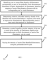
- the system 100 identifies all illuminators that are responsible for illumination of each of the zones for which the measured illuminance is below the threshold of illuminance.
- a mapping of each of the illuminators with corresponding zones is maintained in a database of the system 100. Based on this information the system 100 identifies the illuminator(s) responsible for illumination of each of the zones.
- the system 100 determines extent to which illumination of each of the IR illuminators is to be adjusted.
- the mechanism of determining whether or not to control intensity of each of the IR emitters, based on the difference in the measured illumination and the threshold of illumination serves as a feedback mechanism which allows controlling the intensity of the IR emitters only if necessary i.e. only when the measured illuminance of any of the zones does not match the threshold of illuminance.
- the system 100 generates a control signal to control the intensity of illumination of the one or more illuminators, to increase/improve the illumination of the corresponding zone of the at least one image to at least match the threshold of illumination.
- the generated control signal may be a Pulse Width Modulation (PWM) signal.
- PWM Pulse Width Modulation
- the zone-wise estimated PWM control values are used to vary and adapt the intensity of IR illuminators accordingly at step 308.
- steps in methods 200 and 300 may be performed in the same order depicted or in any alternate order as may be technically feasible. In another embodiment, one or more steps in methods 200 and 300 may be omitted.
- the embodiments of present disclosure herein address unresolved problem of illumination of objects in low-light conditions.
- the embodiment thus provides a mechanism for determining whether or not to control intensity of IR illuminators, based on difference between a zone-wise measured illuminance and a threshold of illuminance.
- the embodiments herein further provide a mechanism to selectively control illumination of one or more of the IR illuminators as required, based on the illumination in respective zones.
- Such computer-readable storage means contain program-code means for implementation of one or more steps of the method, when the program runs on a server or mobile device or any suitable programmable device.
- the hardware device can be any kind of device which can be programmed including e.g., any kind of computer like a server or a personal computer, or the like, or any combination thereof.
- the device may also include means which could be e.g., hardware means like e.g., an application-specific integrated circuit (ASIC), a field-programmable gate array (FPGA), or a combination of hardware and software means, e.g., an ASIC and an FPGA, or at least one microprocessor and at least one memory with software processing components located therein.
- the means can include both hardware means and software means.
- the method embodiments described herein could be implemented in hardware and software.
- the device may also include software means. Alternatively, the embodiments may be implemented on different hardware devices, e.g., using a plurality of CPUs.
- the embodiments herein can comprise hardware and software elements.
- the embodiments that are implemented in software include but are not limited to, firmware, resident software, microcode, etc.
- the functions performed by various components described herein may be implemented in other components or combinations of other components.
- a computer-usable or computer readable medium can be any apparatus that can comprise, store, communicate, propagate, or transport the program for use by or in connection with the instruction execution system, apparatus, or device.
- a computer-readable storage medium refers to any type of physical memory on which information or data readable by a processor may be stored.
- a computer-readable storage medium may store instructions for execution by one or more processors, including instructions for causing the processor(s) to perform steps or stages consistent with the embodiments described herein.
- the term "computer-readable medium” should be understood to include tangible items and exclude carrier waves and transient signals, i.e., be non-transitory. Examples include random access memory (RAM), read-only memory (ROM), volatile memory, nonvolatile memory, hard drives, CD ROMs, DVDs, flash drives, disks, and any other known physical storage media.
Landscapes
- Engineering & Computer Science (AREA)
- Multimedia (AREA)
- Signal Processing (AREA)
- Physics & Mathematics (AREA)
- General Physics & Mathematics (AREA)
- Theoretical Computer Science (AREA)
- Computer Vision & Pattern Recognition (AREA)
- Quality & Reliability (AREA)
- Image Analysis (AREA)
Applications Claiming Priority (1)
| Application Number | Priority Date | Filing Date | Title |
|---|---|---|---|
| IN202121055198 | 2021-11-29 |
Publications (3)
| Publication Number | Publication Date |
|---|---|
| EP4192000A1 true EP4192000A1 (de) | 2023-06-07 |
| EP4192000B1 EP4192000B1 (de) | 2024-04-17 |
| EP4192000C0 EP4192000C0 (de) | 2024-04-17 |
Family
ID=84329832
Family Applications (1)
| Application Number | Title | Priority Date | Filing Date |
|---|---|---|---|
| EP22205968.5A Active EP4192000B1 (de) | 2021-11-29 | 2022-11-08 | Verfahren und system zur zonenweisen adaptiven beleuchtung von objekten |
Country Status (2)
| Country | Link |
|---|---|
| US (1) | US12363443B2 (de) |
| EP (1) | EP4192000B1 (de) |
Families Citing this family (2)
| Publication number | Priority date | Publication date | Assignee | Title |
|---|---|---|---|---|
| US12100065B2 (en) * | 2021-10-29 | 2024-09-24 | Snap Inc. | Adding graphical representation of real-world object |
| TWI889057B (zh) * | 2023-12-08 | 2025-07-01 | 宏達國際電子股份有限公司 | 影像拍攝裝置及其影像拍攝方法 |
Citations (5)
| Publication number | Priority date | Publication date | Assignee | Title |
|---|---|---|---|---|
| US20160073853A1 (en) * | 2013-05-15 | 2016-03-17 | Koninklijke Philips N.V. | Imaging a patient's interior |
| CN108960068A (zh) * | 2018-06-05 | 2018-12-07 | 天津大学 | 用于采集手指静脉图像的光源亮度调节装置及方法 |
| WO2020027647A1 (en) * | 2018-07-31 | 2020-02-06 | Kulim Technology Ideas Sdn Bhd | Apparatus and method for imaging |
| US20200154027A1 (en) * | 2015-11-10 | 2020-05-14 | Lumileds Llc | Adaptive light source |
| US20210112647A1 (en) * | 2018-05-07 | 2021-04-15 | Zane Coleman | Angularly varying light emitting device with an imager |
Family Cites Families (3)
| Publication number | Priority date | Publication date | Assignee | Title |
|---|---|---|---|---|
| US9661239B2 (en) * | 2013-04-17 | 2017-05-23 | Digital Makeup Ltd. | System and method for online processing of video images in real time |
| US10331956B2 (en) | 2015-09-23 | 2019-06-25 | Magna Electronics Inc. | Vehicle vision system with detection enhancement using light control |
| WO2017100903A1 (en) | 2015-12-14 | 2017-06-22 | Motion Metrics International Corp. | Method and apparatus for identifying fragmented material portions within an image |
-
2022
- 2022-11-08 EP EP22205968.5A patent/EP4192000B1/de active Active
- 2022-11-11 US US18/054,832 patent/US12363443B2/en active Active
Patent Citations (5)
| Publication number | Priority date | Publication date | Assignee | Title |
|---|---|---|---|---|
| US20160073853A1 (en) * | 2013-05-15 | 2016-03-17 | Koninklijke Philips N.V. | Imaging a patient's interior |
| US20200154027A1 (en) * | 2015-11-10 | 2020-05-14 | Lumileds Llc | Adaptive light source |
| US20210112647A1 (en) * | 2018-05-07 | 2021-04-15 | Zane Coleman | Angularly varying light emitting device with an imager |
| CN108960068A (zh) * | 2018-06-05 | 2018-12-07 | 天津大学 | 用于采集手指静脉图像的光源亮度调节装置及方法 |
| WO2020027647A1 (en) * | 2018-07-31 | 2020-02-06 | Kulim Technology Ideas Sdn Bhd | Apparatus and method for imaging |
Non-Patent Citations (2)
| Title |
|---|
| JAWAHAR MALATHY ET AL: "Vision based inspection system for leather surface defect detection using fast convergence particle swarm optimization ensemble classifier approach", MULTIMEDIA TOOLS AND APPLICATIONS, vol. 80, no. 3, 28 September 2020 (2020-09-28), pages 4203 - 4235, XP037338161, ISSN: 1380-7501, DOI: 10.1007/S11042-020-09727-3 * |
| TARIQ NAZISH ET AL: "Quality Assessment Methods to Evaluate the Performance of Edge Detection Algorithms for Digital Image: A Systematic Literature Review", IEEE ACCESS, IEEE, USA, vol. 9, 14 June 2021 (2021-06-14), pages 87763 - 87776, XP011862255, DOI: 10.1109/ACCESS.2021.3089210 * |
Also Published As
| Publication number | Publication date |
|---|---|
| EP4192000B1 (de) | 2024-04-17 |
| EP4192000C0 (de) | 2024-04-17 |
| US12363443B2 (en) | 2025-07-15 |
| US20230171505A1 (en) | 2023-06-01 |
Similar Documents
| Publication | Publication Date | Title |
|---|---|---|
| JP6702716B2 (ja) | 画像処理装置、画像処理方法及びプログラム | |
| US11037291B2 (en) | System and method for detecting plant diseases | |
| EP4192000B1 (de) | Verfahren und system zur zonenweisen adaptiven beleuchtung von objekten | |
| US10026004B2 (en) | Shadow detection and removal in license plate images | |
| AU2016225841B2 (en) | Predicting accuracy of object recognition in a stitched image | |
| CN109492642B (zh) | 车牌识别方法、装置、计算机设备及存储介质 | |
| RU2630742C1 (ru) | Способ, система и устройство для биометрического распознавания радужной оболочки глаза | |
| US20150254529A1 (en) | Image processing apparatus and image processing method | |
| US10726561B2 (en) | Method, device and system for determining whether pixel positions in an image frame belong to a background or a foreground | |
| EP3255585A1 (de) | Verfahren und vorrichtung zur aktualisierung eines hintergrundmodells | |
| US20210213615A1 (en) | Method and system for performing image classification for object recognition | |
| US11875489B2 (en) | Detecting hybdrid-distance adversarial patches | |
| Russell et al. | Feature-based image patch classification for moving shadow detection | |
| JP6407467B1 (ja) | 画像処理装置、画像処理方法およびプログラム | |
| CN112819834A (zh) | 基于人工智能的胃部病理图像的分类方法和装置 | |
| US20230128352A1 (en) | Method and system for performing image classification for object recognition | |
| CN117409263B (zh) | 一种无人机自动图像校正引导降落方法和计算机存储介质 | |
| CN113887314A (zh) | 车辆行驶方向的识别方法、装置、计算机设备和存储介质 | |
| Kurbatova et al. | Detection of roads from images based on edge segmentation and morphological operations | |
| Karthik et al. | Image quality assessment based outlier detection for face anti-spoofing | |
| KR102263573B1 (ko) | 하알 대조 특징을 이용한 카메라 영상의 대상물 검출 방법 | |
| JP4749879B2 (ja) | 顔判別方法および装置並びにプログラム | |
| KR20230000385A (ko) | 객체를 인식하기 위한 방법, 시스템 및 비일시성의 컴퓨터 판독 가능한 기록 매체 | |
| CN112347899B (zh) | 一种运动目标图像提取方法、装置、设备及存储介质 | |
| Battiato et al. | Boosting gray codes for red eyes removal |
Legal Events
| Date | Code | Title | Description |
|---|---|---|---|
| PUAI | Public reference made under article 153(3) epc to a published international application that has entered the european phase |
Free format text: ORIGINAL CODE: 0009012 |
|
| STAA | Information on the status of an ep patent application or granted ep patent |
Free format text: STATUS: THE APPLICATION HAS BEEN PUBLISHED |
|
| STAA | Information on the status of an ep patent application or granted ep patent |
Free format text: STATUS: REQUEST FOR EXAMINATION WAS MADE |
|
| AK | Designated contracting states |
Kind code of ref document: A1 Designated state(s): AL AT BE BG CH CY CZ DE DK EE ES FI FR GB GR HR HU IE IS IT LI LT LU LV MC ME MK MT NL NO PL PT RO RS SE SI SK SM TR |
|
| 17P | Request for examination filed |
Effective date: 20230512 |
|
| RBV | Designated contracting states (corrected) |
Designated state(s): AL AT BE BG CH CY CZ DE DK EE ES FI FR GB GR HR HU IE IS IT LI LT LU LV MC ME MK MT NL NO PL PT RO RS SE SI SK SM TR |
|
| GRAP | Despatch of communication of intention to grant a patent |
Free format text: ORIGINAL CODE: EPIDOSNIGR1 |
|
| STAA | Information on the status of an ep patent application or granted ep patent |
Free format text: STATUS: GRANT OF PATENT IS INTENDED |
|
| RIC1 | Information provided on ipc code assigned before grant |
Ipc: G06V 10/44 20220101ALI20231013BHEP Ipc: G06T 7/00 20170101ALI20231013BHEP Ipc: G06V 20/64 20220101ALI20231013BHEP Ipc: G06V 10/141 20220101ALI20231013BHEP Ipc: H04N 23/74 20230101ALI20231013BHEP Ipc: H04N 23/71 20230101ALI20231013BHEP Ipc: H04N 23/61 20230101ALI20231013BHEP Ipc: H04N 23/56 20230101ALI20231013BHEP Ipc: H04N 23/50 20230101ALI20231013BHEP Ipc: G06T 7/70 20170101ALI20231013BHEP Ipc: G06T 7/194 20170101ALI20231013BHEP Ipc: G06T 7/13 20170101ALI20231013BHEP Ipc: G06T 7/12 20170101ALI20231013BHEP Ipc: G06T 7/11 20170101ALI20231013BHEP Ipc: G06T 7/10 20170101ALI20231013BHEP Ipc: H04N 5/272 20060101AFI20231013BHEP |
|
| INTG | Intention to grant announced |
Effective date: 20231108 |
|
| GRAS | Grant fee paid |
Free format text: ORIGINAL CODE: EPIDOSNIGR3 |
|
| GRAA | (expected) grant |
Free format text: ORIGINAL CODE: 0009210 |
|
| STAA | Information on the status of an ep patent application or granted ep patent |
Free format text: STATUS: THE PATENT HAS BEEN GRANTED |
|
| AK | Designated contracting states |
Kind code of ref document: B1 Designated state(s): AL AT BE BG CH CY CZ DE DK EE ES FI FR GB GR HR HU IE IS IT LI LT LU LV MC ME MK MT NL NO PL PT RO RS SE SI SK SM TR |
|
| REG | Reference to a national code |
Ref country code: GB Ref legal event code: FG4D |
|
| REG | Reference to a national code |
Ref country code: CH Ref legal event code: EP |
|
| REG | Reference to a national code |
Ref country code: DE Ref legal event code: R096 Ref document number: 602022002936 Country of ref document: DE |
|
| REG | Reference to a national code |
Ref country code: IE Ref legal event code: FG4D |
|
| U01 | Request for unitary effect filed |
Effective date: 20240417 |
|
| U07 | Unitary effect registered |
Designated state(s): AT BE BG DE DK EE FI FR IT LT LU LV MT NL PT SE SI Effective date: 20240422 |
|
| PG25 | Lapsed in a contracting state [announced via postgrant information from national office to epo] |
Ref country code: IS Free format text: LAPSE BECAUSE OF FAILURE TO SUBMIT A TRANSLATION OF THE DESCRIPTION OR TO PAY THE FEE WITHIN THE PRESCRIBED TIME-LIMIT Effective date: 20240817 |
|
| PG25 | Lapsed in a contracting state [announced via postgrant information from national office to epo] |
Ref country code: HR Free format text: LAPSE BECAUSE OF FAILURE TO SUBMIT A TRANSLATION OF THE DESCRIPTION OR TO PAY THE FEE WITHIN THE PRESCRIBED TIME-LIMIT Effective date: 20240417 |
|
| PG25 | Lapsed in a contracting state [announced via postgrant information from national office to epo] |
Ref country code: GR Free format text: LAPSE BECAUSE OF FAILURE TO SUBMIT A TRANSLATION OF THE DESCRIPTION OR TO PAY THE FEE WITHIN THE PRESCRIBED TIME-LIMIT Effective date: 20240718 |
|
| PG25 | Lapsed in a contracting state [announced via postgrant information from national office to epo] |
Ref country code: ES Free format text: LAPSE BECAUSE OF FAILURE TO SUBMIT A TRANSLATION OF THE DESCRIPTION OR TO PAY THE FEE WITHIN THE PRESCRIBED TIME-LIMIT Effective date: 20240417 |
|
| PG25 | Lapsed in a contracting state [announced via postgrant information from national office to epo] |
Ref country code: PL Free format text: LAPSE BECAUSE OF FAILURE TO SUBMIT A TRANSLATION OF THE DESCRIPTION OR TO PAY THE FEE WITHIN THE PRESCRIBED TIME-LIMIT Effective date: 20240417 |
|
| PG25 | Lapsed in a contracting state [announced via postgrant information from national office to epo] |
Ref country code: PL Free format text: LAPSE BECAUSE OF FAILURE TO SUBMIT A TRANSLATION OF THE DESCRIPTION OR TO PAY THE FEE WITHIN THE PRESCRIBED TIME-LIMIT Effective date: 20240417 Ref country code: NO Free format text: LAPSE BECAUSE OF FAILURE TO SUBMIT A TRANSLATION OF THE DESCRIPTION OR TO PAY THE FEE WITHIN THE PRESCRIBED TIME-LIMIT Effective date: 20240717 Ref country code: IS Free format text: LAPSE BECAUSE OF FAILURE TO SUBMIT A TRANSLATION OF THE DESCRIPTION OR TO PAY THE FEE WITHIN THE PRESCRIBED TIME-LIMIT Effective date: 20240817 Ref country code: HR Free format text: LAPSE BECAUSE OF FAILURE TO SUBMIT A TRANSLATION OF THE DESCRIPTION OR TO PAY THE FEE WITHIN THE PRESCRIBED TIME-LIMIT Effective date: 20240417 Ref country code: GR Free format text: LAPSE BECAUSE OF FAILURE TO SUBMIT A TRANSLATION OF THE DESCRIPTION OR TO PAY THE FEE WITHIN THE PRESCRIBED TIME-LIMIT Effective date: 20240718 Ref country code: ES Free format text: LAPSE BECAUSE OF FAILURE TO SUBMIT A TRANSLATION OF THE DESCRIPTION OR TO PAY THE FEE WITHIN THE PRESCRIBED TIME-LIMIT Effective date: 20240417 Ref country code: RS Free format text: LAPSE BECAUSE OF FAILURE TO SUBMIT A TRANSLATION OF THE DESCRIPTION OR TO PAY THE FEE WITHIN THE PRESCRIBED TIME-LIMIT Effective date: 20240717 |
|
| U20 | Renewal fee for the european patent with unitary effect paid |
Year of fee payment: 3 Effective date: 20241127 |
|
| REG | Reference to a national code |
Ref country code: DE Ref legal event code: R097 Ref document number: 602022002936 Country of ref document: DE |
|
| PG25 | Lapsed in a contracting state [announced via postgrant information from national office to epo] |
Ref country code: CZ Free format text: LAPSE BECAUSE OF FAILURE TO SUBMIT A TRANSLATION OF THE DESCRIPTION OR TO PAY THE FEE WITHIN THE PRESCRIBED TIME-LIMIT Effective date: 20240417 |
|
| PG25 | Lapsed in a contracting state [announced via postgrant information from national office to epo] |
Ref country code: SK Free format text: LAPSE BECAUSE OF FAILURE TO SUBMIT A TRANSLATION OF THE DESCRIPTION OR TO PAY THE FEE WITHIN THE PRESCRIBED TIME-LIMIT Effective date: 20240417 Ref country code: RO Free format text: LAPSE BECAUSE OF FAILURE TO SUBMIT A TRANSLATION OF THE DESCRIPTION OR TO PAY THE FEE WITHIN THE PRESCRIBED TIME-LIMIT Effective date: 20240417 |
|
| PG25 | Lapsed in a contracting state [announced via postgrant information from national office to epo] |
Ref country code: SM Free format text: LAPSE BECAUSE OF FAILURE TO SUBMIT A TRANSLATION OF THE DESCRIPTION OR TO PAY THE FEE WITHIN THE PRESCRIBED TIME-LIMIT Effective date: 20240417 |
|
| PG25 | Lapsed in a contracting state [announced via postgrant information from national office to epo] |
Ref country code: SM Free format text: LAPSE BECAUSE OF FAILURE TO SUBMIT A TRANSLATION OF THE DESCRIPTION OR TO PAY THE FEE WITHIN THE PRESCRIBED TIME-LIMIT Effective date: 20240417 Ref country code: SK Free format text: LAPSE BECAUSE OF FAILURE TO SUBMIT A TRANSLATION OF THE DESCRIPTION OR TO PAY THE FEE WITHIN THE PRESCRIBED TIME-LIMIT Effective date: 20240417 Ref country code: RO Free format text: LAPSE BECAUSE OF FAILURE TO SUBMIT A TRANSLATION OF THE DESCRIPTION OR TO PAY THE FEE WITHIN THE PRESCRIBED TIME-LIMIT Effective date: 20240417 Ref country code: CZ Free format text: LAPSE BECAUSE OF FAILURE TO SUBMIT A TRANSLATION OF THE DESCRIPTION OR TO PAY THE FEE WITHIN THE PRESCRIBED TIME-LIMIT Effective date: 20240417 |
|
| PLBE | No opposition filed within time limit |
Free format text: ORIGINAL CODE: 0009261 |
|
| STAA | Information on the status of an ep patent application or granted ep patent |
Free format text: STATUS: NO OPPOSITION FILED WITHIN TIME LIMIT |
|
| 26N | No opposition filed |
Effective date: 20250120 |
|
| PG25 | Lapsed in a contracting state [announced via postgrant information from national office to epo] |
Ref country code: MC Free format text: LAPSE BECAUSE OF FAILURE TO SUBMIT A TRANSLATION OF THE DESCRIPTION OR TO PAY THE FEE WITHIN THE PRESCRIBED TIME-LIMIT Effective date: 20240417 |
|
| PG25 | Lapsed in a contracting state [announced via postgrant information from national office to epo] |
Ref country code: IE Free format text: LAPSE BECAUSE OF NON-PAYMENT OF DUE FEES Effective date: 20241108 |
|
| REG | Reference to a national code |
Ref country code: CH Ref legal event code: U11 Free format text: ST27 STATUS EVENT CODE: U-0-0-U10-U11 (AS PROVIDED BY THE NATIONAL OFFICE) Effective date: 20251201 |
|
| U20 | Renewal fee for the european patent with unitary effect paid |
Year of fee payment: 4 Effective date: 20251126 |
|
| PGFP | Annual fee paid to national office [announced via postgrant information from national office to epo] |
Ref country code: CH Payment date: 20251201 Year of fee payment: 4 |
|
| PG25 | Lapsed in a contracting state [announced via postgrant information from national office to epo] |
Ref country code: HU Free format text: LAPSE BECAUSE OF FAILURE TO SUBMIT A TRANSLATION OF THE DESCRIPTION OR TO PAY THE FEE WITHIN THE PRESCRIBED TIME-LIMIT; INVALID AB INITIO Effective date: 20221108 |