EP4191834A1 - Rotating electrical machine and method for manufacturing same - Google Patents
Rotating electrical machine and method for manufacturing same Download PDFInfo
- Publication number
- EP4191834A1 EP4191834A1 EP20948697.6A EP20948697A EP4191834A1 EP 4191834 A1 EP4191834 A1 EP 4191834A1 EP 20948697 A EP20948697 A EP 20948697A EP 4191834 A1 EP4191834 A1 EP 4191834A1
- Authority
- EP
- European Patent Office
- Prior art keywords
- magnet
- rotor
- press
- electrical machine
- rotating electrical
- Prior art date
- Legal status (The legal status is an assumption and is not a legal conclusion. Google has not performed a legal analysis and makes no representation as to the accuracy of the status listed.)
- Granted
Links
Images






Classifications
-
- H—ELECTRICITY
- H02—GENERATION; CONVERSION OR DISTRIBUTION OF ELECTRIC POWER
- H02K—DYNAMO-ELECTRIC MACHINES
- H02K1/00—Details of the magnetic circuit
- H02K1/06—Details of the magnetic circuit characterised by the shape, form or construction
- H02K1/22—Rotating parts of the magnetic circuit
- H02K1/27—Rotor cores with permanent magnets
- H02K1/2706—Inner rotors
- H02K1/272—Inner rotors the magnetisation axis of the magnets being perpendicular to the rotor axis
- H02K1/274—Inner rotors the magnetisation axis of the magnets being perpendicular to the rotor axis the rotor consisting of two or more circumferentially positioned magnets
- H02K1/2753—Inner rotors the magnetisation axis of the magnets being perpendicular to the rotor axis the rotor consisting of two or more circumferentially positioned magnets the rotor consisting of magnets or groups of magnets arranged with alternating polarity
- H02K1/278—Surface mounted magnets; Inset magnets
-
- H—ELECTRICITY
- H02—GENERATION; CONVERSION OR DISTRIBUTION OF ELECTRIC POWER
- H02K—DYNAMO-ELECTRIC MACHINES
- H02K1/00—Details of the magnetic circuit
- H02K1/06—Details of the magnetic circuit characterised by the shape, form or construction
- H02K1/22—Rotating parts of the magnetic circuit
- H02K1/28—Means for mounting or fastening rotating magnetic parts on to, or to, the rotor structures
-
- H—ELECTRICITY
- H02—GENERATION; CONVERSION OR DISTRIBUTION OF ELECTRIC POWER
- H02K—DYNAMO-ELECTRIC MACHINES
- H02K15/00—Processes or apparatus specially adapted for manufacturing, assembling, maintaining or repairing of dynamo-electric machines
- H02K15/02—Processes or apparatus specially adapted for manufacturing, assembling, maintaining or repairing of dynamo-electric machines of stator or rotor bodies
- H02K15/03—Processes or apparatus specially adapted for manufacturing, assembling, maintaining or repairing of dynamo-electric machines of stator or rotor bodies having permanent magnets
-
- H—ELECTRICITY
- H02—GENERATION; CONVERSION OR DISTRIBUTION OF ELECTRIC POWER
- H02K—DYNAMO-ELECTRIC MACHINES
- H02K2201/00—Specific aspects not provided for in the other groups of this subclass relating to the magnetic circuits
- H02K2201/06—Magnetic cores, or permanent magnets characterised by their skew
Definitions
- the present disclosure relates to a rotating electrical machine and a method for manufacturing the same.
- Patent Document 1 discloses that a magnet holder is insert-molded with a rotor formed from stacked steel sheets and magnets are press-fitted and fixed between magnet holder parts from a rotary shaft direction.
- Patent Document 2 discloses that a magnet holder molded with resin is fixed to a rotor, and from a rotary shaft direction, a magnet is press-fitted and fixed into a magnet storage portion formed by the magnet holder and the outer circumferential surface of the rotor.
- Patent Document 1 in which the magnet holder is insert-molded with the rotor in advance requires a complicated and expensive mold for insert molding, so that equipment investment increases and the product cost inevitably increases.
- Patent Document 2 In the configuration of Patent Document 2 in which the integrated-type magnet holder is fixed to the rotor and a magnet is press-fitted and fixed into the magnet storage portion formed by the magnet holder and the outer circumferential surface of the rotor, attachment error of the rotor, molding error of the magnet holder, and assembly error such as deformation of the magnet holder due to assembly are added, thus causing a problem that variation in arrangement accuracy of magnets increases.
- the present disclosure has been made to solve the above problem, and an object of the present disclosure is to provide a rotating electrical machine that enables improvement in assembly accuracy and reduction in torque ripple and cogging torque without the need of a mold for insert molding.
- a rotating electrical machine includes: a rotor fixed to a rotary shaft; a plurality of magnets arranged on an outer circumference of the rotor; and holders arranged between the plurality of magnets and fixing the magnets.
- the rotor is provided with a positioning portion that positions each magnet, and a groove for press-fitting and fixing each holder.
- Each holder is provided with a press-fit portion press-fitted into the groove, and a pressing portion for fixing the magnet. By the press-fit portion being press-fitted into the groove, the pressing portion presses and fixes an end of the magnet positioned by the positioning portion.
- the rotating electrical machine according to the present disclosure does not require a complicated and expensive mold for insert molding, does not cause damage to the magnet and the magnet holder at the time of press-fitting, and enables improvement in assembly accuracy, thus obtaining characteristics in which torque ripple and cogging torque are small.
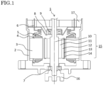
- FIG. 1 is a sectional view illustrating the configuration of the rotating electrical machine.
- a frame 2 which is a housing of a rotating electrical machine 1 is formed in substantially a cylindrical shape having an opening on the rear side (upper side in the drawing), and is made of an aluminum alloy which is inexpensive and light.
- a stator 3 is formed by stacking electromagnetic steel sheets and is fixed to the frame 2.
- the stator 3 has a stator winding 5 wound therearound while an insulator 4 which is an insulating material is interposed therebetween, and is provided with a terminal 6 for supplying the stator winding 5 with current from the control device (not shown) provided on the rear side.
- a bearing 7 is fixed on the front side and a bearing 9 is fixed on the rear side via a bearing holder 8.
- a rotor 11 formed by stacking electromagnetic steel sheets is fixed to a rotor shaft 10, a plurality of magnets 12 are fixed at the outer circumference of the rotor 11 by magnet holders 13, and these are covered by a nonmagnetic protection tube 14, thus forming a rotor unit 15.
- the rotor shaft 10 is rotatably supported by the bearing 7 and the bearing 9, and the rotor unit 15 is provided so as to be surrounded by the stator 3 separately therefrom.
- a joint 16 for attachment to the vehicle side is provided on the front side (lower side in the drawing) of the rotor shaft 10, and a rotation angle detection sensor for detecting the rotation state of the rotor 11 is provided at a part (not shown) on the rear side of the rotor shaft 10.
- a heatsink 17 at which the control device (not shown) is provided is fixed at a rear-side opening end of the frame 2.
- the control device includes a power conversion circuit having a power semiconductor for converting DC current from outside, and a control circuit, and supplies desired current to the stator winding 5 via the terminal 6.
- a rotational force is generated on the rotor 11, so that the rotor unit 15 and therefore the joint 16 are rotated.
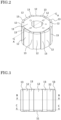
- FIG. 2 and FIG. 3 are a perspective view and a side view showing an assembled state of the rotor 11, the magnets 12, and the magnet holders 13.
- a plurality of magnets 12 are arranged at equal intervals around the outer circumference of the rotor 11, and between the magnets 12, the same number of magnet holders 13 as the magnets 12 are arranged for fixing and retaining the magnets 12.
- FIG. 4 is a perspective view of the rotor 11.
- the rotor 11 is formed from stacked steel sheets which are a plurality of electromagnetic steel sheets stacked in the up-down direction.
- the outer shape of the rotor 11 is substantially an octagonal prism shape having eight outer circumferential surfaces 11a, and the rotor 11 has, at the center, a through hole 11b for inserting the rotor shaft 10.
- positioning bosses 11c, 11d for determining the positions of the magnets 12 in the circumferential direction, and positioning bosses 11e, 11f for determining the positions of the magnets 12 in the axial direction are formed. Grooves 11g extending in the axial direction are formed between the magnets 12.
- FIG. 5 is a perspective view of the magnet 12.
- the magnet 12 is, for example, a Nd-Fe-B based sintered magnet, and the surface thereof has a rust-proof coating.
- the magnet 12 has substantially a semi-cylindrical shape having one cylindrical surface 12a, a flat surface 12b opposed thereto, two side surfaces 12c, 12d, an upper surface 12e, and a lower surface 12f.
- the magnets 12 are arranged on the eight side surfaces of the rotor 11, at equal intervals in the circumferential direction of the rotor shaft 10.
- FIG. 6 is a perspective view of the magnet holder 13.
- the magnet holder 13 is a high-stiffness and elastic molded product of epoxy based resin, polyphenylene sulfide (PPS) based resin, or polybutylene terephthalate (PBT) based resin.
- the cross-section of the magnet holder 13 has substantially a T shape, and the magnet holder 13 has a press-fit portion 13a, and a first contact portion 13b and a second contact portion 13c for each pressing the cylindrical surface 12a of the magnet 12 in the radial direction.
- the magnet holder 13 has a third contact portion 13d for pressing the side surface 12c of the magnet 12 in the circumferential direction, a non-contact portion 13e which does not contact with the side surface 12d of the magnet 12, and a fourth contact portion 13f for pressing the upper surface 12e of the magnet 12 in the axial direction.
- FIG. 7 is a perspective view showing a state before fixation by the magnet holders 13.
- eight magnets 12 are arranged and eight magnet holders 13 are moved in the radial direction (arrow direction) simultaneously, so as to press-fit the press-fit portions 13a into the grooves 11g of the rotor 11.
- the assembled state shown in FIG. 2 and FIG. 3 is obtained.
- FIG. 8 is a sectional view along line A-A in FIG. 2 .
- FIG. 9 and FIG. 10 are partial enlarged sectional views along line B-B and line C-C in FIG. 3 , respectively.
- the upper surface 12e of the magnet 12 is pressed by the fourth contact portion 13f of the magnet holder 13, and the lower surface 12f and the positioning bosses 11e, 11f of the rotor 11 contact with each other, whereby the magnet 12 is positioned and fixed.
- the cylindrical surface 12a of the magnet 12 is pressed by the first contact portion 13b and the second contact portion 13c of the magnet holders 13, and the flat surface 12b and the outer circumferential surface 11a of the rotor 11 contact with each other, whereby the magnet 12 is positioned and fixed.
- One side surface 12c of the magnet 12 is pressed by the third contact portion 13d of the magnet holder 13, and the other side surface 12d and the positioning bosses 11c, 11d of the rotor 11 contact with each other, whereby the magnet 12 is positioned and fixed.
- the non-contact portion 13e of the magnet holder 13 is separate from the side surface 12d of the magnet 12 without pressing the side surface 12d.
- the magnet holder 13 is a molded product of resin, but may be a cast product of nonmagnetic metal such as aluminum or stainless steel, a product worked by cutting or pressing, or the like.
- each magnet holder 13 is press-fitted and fixed into the rotor 11 from the radial direction of the rotor shaft 10, it is possible to easily perform assembly without rubbing the magnet 12 against the rotor 11 and the magnet holder 13 when press-fitting the magnet 12.
- the magnet 12 need not be moved in the axial direction and the circumferential direction, and therefore assembly can be performed more easily.
- such a phenomenon in which the coating of the magnet 12 is removed so that rust occurs or the magnet holder 13 is grazed so that arrangement accuracy and a retention force for the magnets are deteriorated, does not happen.
- the magnets 12 are fixed with high accuracy depending on only accuracy of parts of the rotor 11 without being influenced by accuracy of parts of the magnet holders 13 and assembly accuracy of the magnet holders 13 and the rotor 11.
- a rotating electrical machine having favorable characteristics in which occurrence of torque ripple and cogging torque is suppressed can be provided.
- the flat surface 12b is assuredly pressed against the outer circumferential surface 11a of the rotor 11 without backlash therebetween.
- the rotor 11 has substantially an octagonal prism shape.
- the number of the magnets is not limited thereto, the shape thereof may be another shape such as a segment type, and also the rotor 11 may have another shape such as a cylindrical shape.
- FIG. 11 is a perspective view of the rotor unit 15.
- the protection tube 14 formed by deep drawing and made of a nonmagnetic material such as stainless steel or aluminum is externally fitted to the outer side of the magnet holders 13 fixed as described above.
- the outer circumference of the magnet holders 13 is set to be slightly greater than the outer circumference of the magnets 12.
- the protection tube 14 is fixed to the magnet holders 13 in a slightly press-fitted manner, and then end surfaces thereof are bent so as to be fixed in contact with the upper and lower surfaces of the magnet holders 13 or the rotor 11.
- the rotor unit 15 may be formed without the protection tube 14, but the protection tube 14 is attached in order to prevent the rotor unit 15 from being locked when the magnet 12 cracks or comes off.
- the magnet holders 13 and the magnets 12 are fixed and retained more strongly by the protection tube 14.
- the rotor shaft 10 is press-fitted into the through hole 11b of the rotor 11, whereby the rotor unit 15 is completed.
- the rotor shaft 10 is press-fitted and fixed after the magnets are fixed to the rotor 11.
- the magnets 12 may be fixed through the above-described procedure after the rotor 11 is press-fitted and fixed to the rotor shaft 10.
- the rotating electrical machine of embodiment 1 can be formed using a small-sized holder, and therefore a complicated and expensive mold for insert molding is not needed and an inexpensive holder can be used.
- the positions of the magnets are determined with high accuracy depending on only accuracy of the rotor without being influenced by accuracy of the holders and assembly accuracy of the holders and the rotor, favorable characteristics in which torque ripple and cogging torque are reduced are obtained.
- each holder is fixed to the rotor from the radial direction of the rotary shaft, press-fitting work for the magnets is not needed and assembly can be easily performed.
- the magnet is not grazed during assembling, an effect of obtaining a rotating electrical machine having high reliability without occurrence of rust and deterioration in accuracy, is provided.
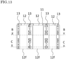
- FIG. 12 and FIG. 13 are a perspective view and a side view showing an assembled state of the rotor 11, the magnets 12, and the magnet holders 13 in embodiment 2.
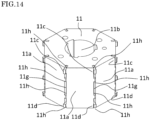
- FIG. 14 is a perspective view of the rotor 11, and
- FIG. 15 is a perspective view of the magnet holder 13.
- the magnet 12 is the same as that in embodiment 1. Description of the same configurations and operations as those in embodiment 1 is omitted.
- the magnet holder 13 has claw portions 13g at four locations that are upper and lower surfaces and locations therebetween.
- the press-fit portion 13a is divided into three parts, and the third contact portion 13d and the non-contact portion 13e are each divided into three parts.
- the base of the claw portion 13g is connected to the main body via a thin deflection portion 13h, and a projection 13i which projects relative to the surrounding back surface is formed in a central area of the deflection portion 13h.
- recesses that are a hole 13j and an elongated hole 13k are formed.
- FIG. 16 is a sectional view along line D-D in FIG. 12 , and the left side with respect to the center shows only the rotor 11 with no magnet holder 13 attached, for facilitating the understanding of the structure of the engagement portions 11h. Since the rotor 11 is formed by stacking electromagnetic steel sheets in the up-down direction, there is no difficulty in forming such a complicated shape.
- the configuration, method, and operation of positioning and fixation for the magnets 12 are the same as those in embodiment 1, and sectional views along line B-B and line C-C in FIG. 13 are also the same as FIG. 9 and FIG. 10 .
- the claw portions 13g of the magnet holder 13 are hooked on the engagement portions 11h of the rotor 11 as shown on the right side with respect to the center in FIG. 16 .
- the retention force is further increased against a centrifugal force generated in the radial direction during rotation.
- the axial-direction position of the magnet 12 is determined by the positioning bosses 11e, 11f of the rotor 11, whereas in the present embodiment, positioning is also made by engagement between the engagement portion 11h at the axial-direction end of the magnet 12 and the claw portion 13g at the axial-direction end, and therefore assembly is performed such that the lower surface of the rotor 11 and the lower surface 12f of the magnet are flush with each other.
- positioning in the axial direction may be made by the positioning bosses 11e, 11f as in embodiment 1.
- FIG. 17 shows a state before the magnet holders 13 are press-fitted
- FIG. 18 shows a state after the magnet holders 13 are press-fitted.
- the rotor 11 and eight magnets 12 are arranged at a fixed jig 100, and the magnet holders 13 are arranged at eight movable jigs 101, using the holes 13j and the elongated holes 13k (shown in FIG. 15B ) as a reference.
- the eight movable jigs 101 are moved in the radial direction simultaneously, so that the press-fit portions 13a of the magnet holders 13 are press-fitted into the grooves 11g of the rotor 11.
- the claw portions 13g of the magnet holders 13 contact with the rotor 11 and move while warping upward or downward.
- the claw portion 13g deflects also in the radial direction and thus is smoothly hooked on the engagement portion 11h of the rotor 11.
- the claw portion 13g returns from its deflected state and is fixed to the engagement portion 11h of the rotor 11 without backlash.
- come-off prevention in the radial direction can be achieved with simple work of inserting the magnet holder 13 from the radial direction, and thus stronger retention in the radial direction can be made without providing another part or another process.
- a mechanism for come-off prevention is made by the claw portion 13g, but as a matter of course, such a come-off prevention mechanism may be made by another process such as adhesion, crimping, screw fastening, or pin fastening.
- the configuration and assembly method of the rotor unit 15 are the same as those in embodiment 1.
- two rotors 11 are shifted from each other by a predetermined angle (several degrees) in the circumferential direction, and are stacked at two stages in the axial direction. These two rotors 11 are press-fitted and fixed to the rotor shaft 10. Then, the magnets 12 are fixed to the above two rotors 11 by the magnet holders 13.
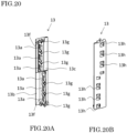
- FIG. 20 is a perspective view of the magnet holder ( FIG. 20A is a front view and FIG. 20B is a back view).
- This magnet holder has such a shape that two magnet holders in embodiment 2 are shifted from each other by a predetermined angle in the circumferential direction as with the rotor 11 and are stacked in the axial direction so as to be integrally formed.
- FIG. 21 and FIG. 22 are a top view of the magnet holder 13 and a top view (partial enlarged view) of the rotor 11, respectively.
- the press-fit portions 13a and the claw portions 13g of the magnet holder 13 are formed to be parallel on the upper side and the lower side of the axial-direction stacked shape, and the grooves 11g and the grooves of the engagement portions 11h of the rotor 11 are also formed to be parallel on the upper side and the lower side of the axial-direction stacked shape.
- the magnet holder 13 can be smoothly press-fitted into the rotor 11 from the radial direction. Assembly is performed in the same manner as in embodiment 1 and embodiment 2, that is, as shown in FIG. 23 , in a state in which all the magnets 12 are set to the rotor, the magnet holders 13 are moved in the radial direction simultaneously so as to be press-fitted, thus completing assembly.
- the protection tube 14 is fixed to the magnet holders 13 in a slightly press-fitted manner, and then end surfaces thereof are bent so as to be fixed in contact with the upper and lower surfaces of the magnet holders 13 or the rotor 11, whereby the rotor unit 15 is completed.
- the two rotors 11 shifted from each other by a predetermined angle (several degrees) in the circumferential direction and stacked in the axial direction are press-fitted and fixed to the rotor shaft 10.
- a product in which the rotors 11 are shifted from each other by a predetermined angle (several degrees) in the circumferential direction may be manufactured as an integrated unit in advance, and then as in embodiments 1 and 2, the magnets 12 may be fixed and the resultant unit may be fixed to the rotor shaft 10. Since the rotors 11 are formed by stacking electromagnetic steel sheets in the up-down direction, there is no difficulty in forming such a complicated shape.
- the rotor unit 15 of a step-skew type can be assembled with one work of press-fitting the magnet holders 13 from the radial direction, without increasing the numbers of the rotors 11 and the magnet holders 13.
- a rotating electrical machine that can be easily assembled and has high accuracy can be provided at low cost. Further, the effects described in embodiments 1 and 2 can be provided.
Landscapes
- Engineering & Computer Science (AREA)
- Power Engineering (AREA)
- Manufacturing & Machinery (AREA)
- Permanent Field Magnets Of Synchronous Machinery (AREA)
- Manufacture Of Motors, Generators (AREA)
Abstract
Description
- The present disclosure relates to a rotating electrical machine and a method for manufacturing the same.
- Conventionally, in a rotating electrical machine in which a rotor unit with magnets fixed thereto rotates on the inner side of a coil, a configuration in which a plurality of magnets are fixed to a rotor by a magnet holder made of resin, without using an adhesive, is known. For example,
Patent Document 1 discloses that a magnet holder is insert-molded with a rotor formed from stacked steel sheets and magnets are press-fitted and fixed between magnet holder parts from a rotary shaft direction. - In addition,
Patent Document 2 discloses that a magnet holder molded with resin is fixed to a rotor, and from a rotary shaft direction, a magnet is press-fitted and fixed into a magnet storage portion formed by the magnet holder and the outer circumferential surface of the rotor. -
- Patent Document 1:
Japanese Patent No. 5842365 - Patent Document 2:
Japanese Patent No. 5044217 - However, the configuration of
Patent Document 1 in which the magnet holder is insert-molded with the rotor in advance requires a complicated and expensive mold for insert molding, so that equipment investment increases and the product cost inevitably increases. - In the configuration of
Patent Document 2 in which the integrated-type magnet holder is fixed to the rotor and a magnet is press-fitted and fixed into the magnet storage portion formed by the magnet holder and the outer circumferential surface of the rotor, attachment error of the rotor, molding error of the magnet holder, and assembly error such as deformation of the magnet holder due to assembly are added, thus causing a problem that variation in arrangement accuracy of magnets increases. - In particular, if position accuracy in the circumferential direction of the rotary shaft varies, torque ripple and cogging torque occur, leading to deterioration in performance of the rotating electrical machine. Further, a magnet needs to be press-fitted and fixed into the magnet storage portion formed by the magnet holder and the outer circumferential surface of the rotor, from the rotary shaft direction. Therefore, workability in assembling is low and the magnet and the magnet holder might be grazed at the time of press-fitting, leading to occurrence of rust, accuracy deterioration, or the like.
- The present disclosure has been made to solve the above problem, and an object of the present disclosure is to provide a rotating electrical machine that enables improvement in assembly accuracy and reduction in torque ripple and cogging torque without the need of a mold for insert molding.
- A rotating electrical machine according to the present disclosure includes: a rotor fixed to a rotary shaft; a plurality of magnets arranged on an outer circumference of the rotor; and holders arranged between the plurality of magnets and fixing the magnets. The rotor is provided with a positioning portion that positions each magnet, and a groove for press-fitting and fixing each holder. Each holder is provided with a press-fit portion press-fitted into the groove, and a pressing portion for fixing the magnet. By the press-fit portion being press-fitted into the groove, the pressing portion presses and fixes an end of the magnet positioned by the positioning portion.
- The rotating electrical machine according to the present disclosure does not require a complicated and expensive mold for insert molding, does not cause damage to the magnet and the magnet holder at the time of press-fitting, and enables improvement in assembly accuracy, thus obtaining characteristics in which torque ripple and cogging torque are small.
-
- [
FIG. 1] FIG. 1 is a sectional view of a rotating electrical machine according toembodiment 1. - [
FIG. 2] FIG. 2 is a perspective view showing an assembled state of a rotor, magnets, and magnet holders of the rotating electrical machine according toembodiment 1. - [
FIG. 3] FIG. 3 is a side view showing an assembled state of the rotor, the magnets, and the magnet holders of the rotating electrical machine according toembodiment 1. - [
FIG. 4] FIG. 4 is a perspective view of the rotor of the rotating electrical machine according toembodiment 1. - [
FIG. 5] FIG. 5 is a perspective view of the magnet of the rotating electrical machine according toembodiment 1. - [
FIG. 6] FIG. 6 is a perspective view of the magnet holder of the rotating electrical machine according toembodiment 1. - [
FIG. 7] FIG. 7 is a perspective view showing a state before fixation by the magnet holders of the rotating electrical machine according toembodiment 1. - [
FIG. 8] FIG. 8 is a sectional view along line A-A inFIG. 2 according toembodiment 1. - [
FIG. 9] FIG. 9 is a partial enlarged sectional view along line B-B inFIG. 3 according toembodiment 1. - [
FIG. 10] FIG. 10 is a partial enlarged sectional view along line C-C inFIG. 3 according toembodiment 1. - [
FIG. 11] FIG. 11 is a perspective view of a rotor unit according toembodiment 1. - [
FIG. 12] FIG. 12 is a perspective view showing an assembled state of a rotor, magnets, and magnet holders of a rotating electrical machine according toembodiment 2. - [
FIG. 13] FIG. 13 is a side view showing an assembled state of the rotor, the magnets, and the magnet holders of the rotating electrical machine according toembodiment 2. - [
FIG. 14] FIG. 14 is a perspective view of the rotor of the rotating electrical machine according toembodiment 2. - [
FIG. 15] FIG. 15 is a perspective view of the magnet holder of the rotating electrical machine according toembodiment 2. - [
FIG. 16] FIG. 16 is a sectional view along line D-D inFIG. 12 according toembodiment 2. - [
FIG. 17] FIG. 17 is a perspective view showing a state before press-fitting of the magnet holders of the rotating electrical machine according toembodiment 2. - [
FIG. 18] FIG. 18 is a perspective view showing a state after press-fitting of the magnet holders of the rotating electrical machine according toembodiment 2. - [
FIG. 19] FIG. 19 is a perspective view showing assembly of a rotor and a rotor shaft according toembodiment 3. - [
FIG. 20] FIG. 20 is a perspective view of a magnet holder according toembodiment 3. - [
FIG. 21] FIG. 21 is a top view of the magnet holder according toembodiment 3. - [
FIG. 22] FIG. 22 is a top view of the rotor according toembodiment 3. - [
FIG. 23] FIG. 23 is a perspective view showing a state before press-fitting of the magnet holders according toembodiment 3. - [
FIG. 24] FIG. 24 is a perspective view of a rotor unit according toembodiment 3. - Hereinafter, a preferred embodiment of a rotating electrical machine according to the present disclosure will be described with reference to the drawings. The same or corresponding matters and parts are denoted by the same reference characters and the detailed description thereof is omitted. Also in the other embodiments, components denoted by the same reference characters will not be repeatedly described.
- The present disclosure is not limited to the description below, and modification can be made as appropriate without deviating from the scope of the present disclosure. In the drawings, for facilitating the understanding, the scales of members may be different from actual ones and components irrelevant to features of the present disclosure are not shown.
- With reference to
FIG. 1 to FIG. 11 , a rotating electrical machine according toembodiment 1 of the present disclosure will be described. - The present embodiment shows an example in which the rotating electrical machine is applied to electric power steering mounted to a vehicle. In order to assist a steering force of the steering of the vehicle, a control device is also needed in addition to the rotating electrical machine itself, but the control device is not shown in the drawings.
FIG. 1 is a sectional view illustrating the configuration of the rotating electrical machine. - A
frame 2 which is a housing of a rotatingelectrical machine 1 is formed in substantially a cylindrical shape having an opening on the rear side (upper side in the drawing), and is made of an aluminum alloy which is inexpensive and light. Astator 3 is formed by stacking electromagnetic steel sheets and is fixed to theframe 2. Thestator 3 has a stator winding 5 wound therearound while an insulator 4 which is an insulating material is interposed therebetween, and is provided with aterminal 6 for supplying the stator winding 5 with current from the control device (not shown) provided on the rear side. In theframe 2, abearing 7 is fixed on the front side and abearing 9 is fixed on the rear side via abearing holder 8. - A
rotor 11 formed by stacking electromagnetic steel sheets is fixed to arotor shaft 10, a plurality ofmagnets 12 are fixed at the outer circumference of therotor 11 bymagnet holders 13, and these are covered by anonmagnetic protection tube 14, thus forming arotor unit 15. Therotor shaft 10 is rotatably supported by thebearing 7 and thebearing 9, and therotor unit 15 is provided so as to be surrounded by thestator 3 separately therefrom. - A
joint 16 for attachment to the vehicle side is provided on the front side (lower side in the drawing) of therotor shaft 10, and a rotation angle detection sensor for detecting the rotation state of therotor 11 is provided at a part (not shown) on the rear side of therotor shaft 10. - A
heatsink 17 at which the control device (not shown) is provided is fixed at a rear-side opening end of theframe 2. The control device includes a power conversion circuit having a power semiconductor for converting DC current from outside, and a control circuit, and supplies desired current to the stator winding 5 via theterminal 6. Thus, a rotational force is generated on therotor 11, so that therotor unit 15 and therefore the joint 16 are rotated. - Next, the configuration of the
rotor unit 15 of the present embodiment will be described in detail. -
FIG. 2 and FIG. 3 are a perspective view and a side view showing an assembled state of therotor 11, themagnets 12, and themagnet holders 13. A plurality ofmagnets 12 are arranged at equal intervals around the outer circumference of therotor 11, and between themagnets 12, the same number ofmagnet holders 13 as themagnets 12 are arranged for fixing and retaining themagnets 12. -
FIG. 4 is a perspective view of therotor 11. Therotor 11 is formed from stacked steel sheets which are a plurality of electromagnetic steel sheets stacked in the up-down direction. In the present embodiment, the outer shape of therotor 11 is substantially an octagonal prism shape having eight outercircumferential surfaces 11a, and therotor 11 has, at the center, a throughhole 11b for inserting therotor shaft 10. Near upper and lower ends of the outer circumference, positioningbosses magnets 12 in the circumferential direction, andpositioning bosses magnets 12 in the axial direction, are formed.Grooves 11g extending in the axial direction are formed between themagnets 12. -
FIG. 5 is a perspective view of themagnet 12. Themagnet 12 is, for example, a Nd-Fe-B based sintered magnet, and the surface thereof has a rust-proof coating. Themagnet 12 has substantially a semi-cylindrical shape having onecylindrical surface 12a, aflat surface 12b opposed thereto, twoside surfaces upper surface 12e, and alower surface 12f. Themagnets 12 are arranged on the eight side surfaces of therotor 11, at equal intervals in the circumferential direction of therotor shaft 10. -
FIG. 6 is a perspective view of themagnet holder 13. Themagnet holder 13 is a high-stiffness and elastic molded product of epoxy based resin, polyphenylene sulfide (PPS) based resin, or polybutylene terephthalate (PBT) based resin. The cross-section of themagnet holder 13 has substantially a T shape, and themagnet holder 13 has a press-fit portion 13a, and afirst contact portion 13b and asecond contact portion 13c for each pressing thecylindrical surface 12a of themagnet 12 in the radial direction. Further, themagnet holder 13 has athird contact portion 13d for pressing theside surface 12c of themagnet 12 in the circumferential direction, anon-contact portion 13e which does not contact with theside surface 12d of themagnet 12, and afourth contact portion 13f for pressing theupper surface 12e of themagnet 12 in the axial direction. -
FIG. 7 is a perspective view showing a state before fixation by themagnet holders 13. For therotor 11, eightmagnets 12 are arranged and eightmagnet holders 13 are moved in the radial direction (arrow direction) simultaneously, so as to press-fit the press-fit portions 13a into thegrooves 11g of therotor 11. Thus, the assembled state shown inFIG. 2 and FIG. 3 is obtained. -
FIG. 8 is a sectional view along line A-A inFIG. 2 .FIG. 9 and FIG. 10 are partial enlarged sectional views along line B-B and line C-C inFIG. 3 , respectively. As shown inFIG. 8 , theupper surface 12e of themagnet 12 is pressed by thefourth contact portion 13f of themagnet holder 13, and thelower surface 12f and thepositioning bosses rotor 11 contact with each other, whereby themagnet 12 is positioned and fixed. - As shown in
FIG. 9 and FIG. 10 , thecylindrical surface 12a of themagnet 12 is pressed by thefirst contact portion 13b and thesecond contact portion 13c of themagnet holders 13, and theflat surface 12b and the outercircumferential surface 11a of therotor 11 contact with each other, whereby themagnet 12 is positioned and fixed. Oneside surface 12c of themagnet 12 is pressed by thethird contact portion 13d of themagnet holder 13, and theother side surface 12d and thepositioning bosses rotor 11 contact with each other, whereby themagnet 12 is positioned and fixed. At this time, thenon-contact portion 13e of themagnet holder 13 is separate from theside surface 12d of themagnet 12 without pressing theside surface 12d. - Here, in order that the
magnet holder 13 will not come off from therotor 11 after press-fitting, designing is made on the basis of a press-fit interference, a press-fit length, materials, and the like, whereby a necessary retention force is ensured. In the present embodiment, themagnet holder 13 is a molded product of resin, but may be a cast product of nonmagnetic metal such as aluminum or stainless steel, a product worked by cutting or pressing, or the like. - With the above configuration, it is possible to provide the
magnet holder 13 with a reduced size and at low cost, without the need of a complicated and expensive mold. In addition, since eachmagnet holder 13 is press-fitted and fixed into therotor 11 from the radial direction of therotor shaft 10, it is possible to easily perform assembly without rubbing themagnet 12 against therotor 11 and themagnet holder 13 when press-fitting themagnet 12. - During assembling, the
magnet 12 need not be moved in the axial direction and the circumferential direction, and therefore assembly can be performed more easily. In addition, such a phenomenon in which the coating of themagnet 12 is removed so that rust occurs or themagnet holder 13 is grazed so that arrangement accuracy and a retention force for the magnets are deteriorated, does not happen. - Further, the
magnets 12 are fixed with high accuracy depending on only accuracy of parts of therotor 11 without being influenced by accuracy of parts of themagnet holders 13 and assembly accuracy of themagnet holders 13 and therotor 11. Thus, a rotating electrical machine having favorable characteristics in which occurrence of torque ripple and cogging torque is suppressed can be provided. - In addition, since the
magnet 12 is assuredly pressed by thefirst contact portion 13b and thesecond contact portion 13c of themagnet holders 13, theflat surface 12b is assuredly pressed against the outercircumferential surface 11a of therotor 11 without backlash therebetween. - In the present embodiment, eight
magnets 12 having a semi-cylindrical shape are used and therotor 11 has substantially an octagonal prism shape. However, as a matter of course, the number of the magnets is not limited thereto, the shape thereof may be another shape such as a segment type, and also therotor 11 may have another shape such as a cylindrical shape. -
FIG. 11 is a perspective view of therotor unit 15. Theprotection tube 14 formed by deep drawing and made of a nonmagnetic material such as stainless steel or aluminum is externally fitted to the outer side of themagnet holders 13 fixed as described above. In the present embodiment, the outer circumference of themagnet holders 13 is set to be slightly greater than the outer circumference of themagnets 12. Theprotection tube 14 is fixed to themagnet holders 13 in a slightly press-fitted manner, and then end surfaces thereof are bent so as to be fixed in contact with the upper and lower surfaces of themagnet holders 13 or therotor 11. - The
rotor unit 15 may be formed without theprotection tube 14, but theprotection tube 14 is attached in order to prevent therotor unit 15 from being locked when themagnet 12 cracks or comes off. In addition, themagnet holders 13 and themagnets 12 are fixed and retained more strongly by theprotection tube 14. Finally, therotor shaft 10 is press-fitted into the throughhole 11b of therotor 11, whereby therotor unit 15 is completed. - In the present embodiment, the
rotor shaft 10 is press-fitted and fixed after the magnets are fixed to therotor 11. However, as a matter of course, themagnets 12 may be fixed through the above-described procedure after therotor 11 is press-fitted and fixed to therotor shaft 10. - As described above, the rotating electrical machine of
embodiment 1 can be formed using a small-sized holder, and therefore a complicated and expensive mold for insert molding is not needed and an inexpensive holder can be used. In addition, since the positions of the magnets are determined with high accuracy depending on only accuracy of the rotor without being influenced by accuracy of the holders and assembly accuracy of the holders and the rotor, favorable characteristics in which torque ripple and cogging torque are reduced are obtained. Further, since each holder is fixed to the rotor from the radial direction of the rotary shaft, press-fitting work for the magnets is not needed and assembly can be easily performed. In addition, since the magnet is not grazed during assembling, an effect of obtaining a rotating electrical machine having high reliability without occurrence of rust and deterioration in accuracy, is provided. - Next, the configuration of the
rotor unit 15 according toembodiment 2 will be described in detail, with reference toFIG. 12 to FIG. 16 . -
FIG. 12 andFIG. 13 are a perspective view and a side view showing an assembled state of therotor 11, themagnets 12, and themagnet holders 13 inembodiment 2.FIG. 14 is a perspective view of therotor 11, andFIG. 15 is a perspective view of themagnet holder 13. Themagnet 12 is the same as that inembodiment 1. Description of the same configurations and operations as those inembodiment 1 is omitted. - As shown in the front view in
FIG. 15A , themagnet holder 13 hasclaw portions 13g at four locations that are upper and lower surfaces and locations therebetween. Thus, the press-fit portion 13a is divided into three parts, and thethird contact portion 13d and thenon-contact portion 13e are each divided into three parts. As shown in the back view inFIG. 15B , the base of theclaw portion 13g is connected to the main body via athin deflection portion 13h, and aprojection 13i which projects relative to the surrounding back surface is formed in a central area of thedeflection portion 13h. On the back side, recesses that are ahole 13j and anelongated hole 13k are formed. - Next, as shown in
FIG. 14 ,engagement portions 11h to be engaged with theclaw portions 13g of themagnet holder 13 are formed at four locations that are upper and lower surfaces of therotor 11 and locations therebetween, for onemagnet holder 13.FIG. 16 is a sectional view along line D-D inFIG. 12 , and the left side with respect to the center shows only therotor 11 with nomagnet holder 13 attached, for facilitating the understanding of the structure of theengagement portions 11h. Since therotor 11 is formed by stacking electromagnetic steel sheets in the up-down direction, there is no difficulty in forming such a complicated shape. - In the above structure, the configuration, method, and operation of positioning and fixation for the
magnets 12 are the same as those inembodiment 1, and sectional views along line B-B and line C-C inFIG. 13 are also the same asFIG. 9 and FIG. 10 . After themagnet holder 13 is press-fitted, theclaw portions 13g of themagnet holder 13 are hooked on theengagement portions 11h of therotor 11 as shown on the right side with respect to the center inFIG. 16 . Thus, the retention force is further increased against a centrifugal force generated in the radial direction during rotation. - In
embodiment 1, the axial-direction position of themagnet 12 is determined by thepositioning bosses rotor 11, whereas in the present embodiment, positioning is also made by engagement between theengagement portion 11h at the axial-direction end of themagnet 12 and theclaw portion 13g at the axial-direction end, and therefore assembly is performed such that the lower surface of therotor 11 and thelower surface 12f of the magnet are flush with each other. Here, positioning in the axial direction may be made by thepositioning bosses embodiment 1. - Next, the details of an assembly method will be specifically described with reference to
FIG. 17 andFIG. 18 .FIG. 17 shows a state before themagnet holders 13 are press-fitted, andFIG. 18 shows a state after themagnet holders 13 are press-fitted. - First, as shown in
FIG. 17 , therotor 11 and eightmagnets 12 are arranged at a fixedjig 100, and themagnet holders 13 are arranged at eightmovable jigs 101, using theholes 13j and theelongated holes 13k (shown inFIG. 15B ) as a reference. - By an upper die (not shown) descending, the eight
movable jigs 101 are moved in the radial direction simultaneously, so that the press-fit portions 13a of themagnet holders 13 are press-fitted into thegrooves 11g of therotor 11. At the same time, theclaw portions 13g of themagnet holders 13 contact with therotor 11 and move while warping upward or downward. At this time, since thethin deflection portion 13h and theprojection 13i projecting relative to the back surface are formed at the base of theclaw portion 13g of themagnet holder 13, theclaw portion 13g deflects also in the radial direction and thus is smoothly hooked on theengagement portion 11h of therotor 11. When themagnet holder 13 is released from themovable jig 101, theclaw portion 13g returns from its deflected state and is fixed to theengagement portion 11h of therotor 11 without backlash. - With the above configuration and assembly method, the effects described in
embodiment 1 are provided and in addition, come-off prevention in the radial direction can be achieved with simple work of inserting themagnet holder 13 from the radial direction, and thus stronger retention in the radial direction can be made without providing another part or another process. In the present embodiment, a mechanism for come-off prevention is made by theclaw portion 13g, but as a matter of course, such a come-off prevention mechanism may be made by another process such as adhesion, crimping, screw fastening, or pin fastening. The configuration and assembly method of therotor unit 15 are the same as those inembodiment 1. - In
embodiment 3, a case where the magnet attachment structure inembodiment 2 is applied to arotor unit 15 of a step-skew type will be described. - As shown in
FIG. 19 , in the present embodiment, tworotors 11 are shifted from each other by a predetermined angle (several degrees) in the circumferential direction, and are stacked at two stages in the axial direction. These tworotors 11 are press-fitted and fixed to therotor shaft 10. Then, themagnets 12 are fixed to the above tworotors 11 by themagnet holders 13. -
FIG. 20 is a perspective view of the magnet holder (FIG. 20A is a front view andFIG. 20B is a back view). This magnet holder has such a shape that two magnet holders inembodiment 2 are shifted from each other by a predetermined angle in the circumferential direction as with therotor 11 and are stacked in the axial direction so as to be integrally formed.FIG. 21 and FIG. 22 are a top view of themagnet holder 13 and a top view (partial enlarged view) of therotor 11, respectively. The press-fit portions 13a and theclaw portions 13g of themagnet holder 13 are formed to be parallel on the upper side and the lower side of the axial-direction stacked shape, and thegrooves 11g and the grooves of theengagement portions 11h of therotor 11 are also formed to be parallel on the upper side and the lower side of the axial-direction stacked shape. - Thus, the
magnet holder 13 can be smoothly press-fitted into therotor 11 from the radial direction. Assembly is performed in the same manner as inembodiment 1 andembodiment 2, that is, as shown inFIG. 23 , in a state in which all themagnets 12 are set to the rotor, themagnet holders 13 are moved in the radial direction simultaneously so as to be press-fitted, thus completing assembly. - Thereafter, as shown in
FIG. 24 , as inembodiment 1, theprotection tube 14 is fixed to themagnet holders 13 in a slightly press-fitted manner, and then end surfaces thereof are bent so as to be fixed in contact with the upper and lower surfaces of themagnet holders 13 or therotor 11, whereby therotor unit 15 is completed. In the present embodiment, the tworotors 11 shifted from each other by a predetermined angle (several degrees) in the circumferential direction and stacked in the axial direction are press-fitted and fixed to therotor shaft 10. However, as a matter of course, a product in which therotors 11 are shifted from each other by a predetermined angle (several degrees) in the circumferential direction may be manufactured as an integrated unit in advance, and then as inembodiments magnets 12 may be fixed and the resultant unit may be fixed to therotor shaft 10. Since therotors 11 are formed by stacking electromagnetic steel sheets in the up-down direction, there is no difficulty in forming such a complicated shape. - As described above, in the present embodiment, the
rotor unit 15 of a step-skew type can be assembled with one work of press-fitting themagnet holders 13 from the radial direction, without increasing the numbers of therotors 11 and themagnet holders 13. Thus, a rotating electrical machine that can be easily assembled and has high accuracy can be provided at low cost. Further, the effects described inembodiments - Although the disclosure is described above in terms of various exemplary embodiments and implementations, it should be understood that the various features, aspects, and functionality described in one or more of the individual embodiments are not limited in their applicability to the particular embodiment with which they are described, but instead can be applied, alone or in various combinations to one or more of the embodiments of the disclosure.
- It is therefore understood that numerous modifications which have not been exemplified can be devised without departing from the scope of the present disclosure. For example, at least one of the constituent components may be modified, added, or eliminated. At least one of the constituent components mentioned in at least one of the preferred embodiments may be selected and combined with the constituent components mentioned in another preferred embodiment.
-
- 1
- rotating electrical machine
- 2
- frame
- 3
- stator
- 4
- insulator
- 5
- stator winding
- 6
- terminal
- 7
- bearing
- 8
- bearing holder
- 9
- bearing
- 10
- rotor shaft
- 11
- rotor
- 11a
- outer circumferential surface
- 11b
- through hole
- 11c, 11d
- positioning boss
- 11e, 11f
- positioning boss
- 11g
- groove
- 11h
- engagement portion
- 12
- magnet
- 13
- magnet holder
- 13a
- press-fit portion
- 13b
- first contact portion
- 13c
- second contact portion
- 13d
- third contact portion
- 13e
- non-contact portion
- 13f
- fourth contact portion
- 13g
- claw portion
- 13h
- deflection portion
- 13i
- projection
- 13j
- hole
- 13k
- elongated hole
- 14
- protection tube
- 15
- rotor unit
- 16
- joint
- 17
- heatsink
- 100
- fixed jig
- 101
- movable jig
Claims (10)
- A rotating electrical machine comprising:a rotor fixed to a rotary shaft;a plurality of magnets arranged on an outer circumference of the rotor; andholders arranged between the plurality of magnets and fixing the magnets, whereinthe rotor is provided with a positioning portion that positions each magnet, and a groove for press-fitting and fixing each holder,each holder is provided with a press-fit portion press-fitted into the groove, and a pressing portion for fixing the magnet, andby the press-fit portion being press-fitted into the groove, the pressing portion presses and fixes an end of the magnet positioned by the positioning portion.
- The rotating electrical machine according to claim 1, whereinthe positioning portion is engaged with one circumferential-direction end of the magnet,the pressing portion is formed on a circumferential-direction side of the press-fit portion, andby the press-fit portion being press-fitted into the groove, the pressing portion presses, in a circumferential direction and a radial direction, another circumferential-direction end of the magnet that is not engaged with the positioning portion.
- The rotating electrical machine according to claim 2, wherein
the pressing portion presses, in the radial direction, the end of the magnet that is engaged with the positioning portion. - The rotating electrical machine according to claim 1, whereinthe positioning portion is formed at one axial-direction end and engaged with the magnet,the pressing portion is formed on an axial-direction side of the holder, andby the press-fit portion being press-fitted into the groove, the pressing portion presses, in an axial direction, another axial-direction end of the magnet that is not engaged with the positioning portion.
- The rotating electrical machine according to any one of claims 1 to 4, wherein
the holder is provided with come-off prevention means for preventing coming off in a radial direction. - The rotating electrical machine according to claim 5, wherein
the come-off prevention means is formed by a claw portion extending from a flexible portion formed integrally with the holder, the flexible portion being elastically displaceable in the radial direction. - The rotating electrical machine according to claim 6, wherein
the press-fit portion and the claw portion of the holder extend in parallel as seen from the rotary shaft direction. - The rotating electrical machine according to any one of claims 1 to 7, wherein
the magnets are stacked at a plurality of stages in the rotary shaft direction, and are arranged so as to be shifted from each other in a circumferential direction between the respective stages. - The rotating electrical machine according to claim 8, wherein
the magnets stacked in an axial direction are integrally fixed by the holder. - A method for manufacturing the rotating electrical machine according to any one of claims 1 to 9, wherein
a plurality of the holders are attached to the rotor simultaneously.
Applications Claiming Priority (1)
| Application Number | Priority Date | Filing Date | Title |
|---|---|---|---|
| PCT/JP2020/029678 WO2022029842A1 (en) | 2020-08-03 | 2020-08-03 | Rotating electrical machine and method for manufacturing same |
Publications (3)
| Publication Number | Publication Date |
|---|---|
| EP4191834A1 true EP4191834A1 (en) | 2023-06-07 |
| EP4191834A4 EP4191834A4 (en) | 2023-09-06 |
| EP4191834B1 EP4191834B1 (en) | 2025-11-26 |
Family
ID=80117146
Family Applications (1)
| Application Number | Title | Priority Date | Filing Date |
|---|---|---|---|
| EP20948697.6A Active EP4191834B1 (en) | 2020-08-03 | 2020-08-03 | Rotating electrical machine and method for manufacturing same |
Country Status (5)
| Country | Link |
|---|---|
| US (1) | US12463480B2 (en) |
| EP (1) | EP4191834B1 (en) |
| JP (1) | JP7403666B2 (en) |
| CN (1) | CN116134701B (en) |
| WO (1) | WO2022029842A1 (en) |
Families Citing this family (1)
| Publication number | Priority date | Publication date | Assignee | Title |
|---|---|---|---|---|
| CN115943541B (en) * | 2020-09-09 | 2025-10-21 | 三菱电机株式会社 | Rotating electric machine and method for manufacturing the same |
Family Cites Families (20)
| Publication number | Priority date | Publication date | Assignee | Title |
|---|---|---|---|---|
| US7687957B2 (en) | 2004-07-16 | 2010-03-30 | Mitsuba Corporation | Magnet fixing structure for electric rotary machine |
| JP4781706B2 (en) * | 2005-04-15 | 2011-09-28 | 三菱電機株式会社 | Permanent magnet type rotating electrical machine and method for manufacturing the rotor |
| KR20070113726A (en) * | 2006-05-26 | 2007-11-29 | 주식회사 대우일렉트로닉스 | Rotor of Surface Mount Magnet Motor |
| WO2010133496A1 (en) * | 2009-05-22 | 2010-11-25 | Arcelik Anonim Sirketi | An electric motor having a permanent magnet rotor |
| JP5842365B2 (en) | 2011-04-02 | 2016-01-13 | 日本電産株式会社 | Rotor unit, rotating electric machine, and method of manufacturing rotor unit |
| CN202713000U (en) * | 2011-09-29 | 2013-01-30 | 西门子公司 | Permanent magnet synchronous motor and rotor thereof |
| JP5966399B2 (en) * | 2012-02-07 | 2016-08-10 | 日本精工株式会社 | Brushless motor and electric power steering device |
| JP5966400B2 (en) * | 2012-02-07 | 2016-08-10 | 日本精工株式会社 | Brushless motor and electric power steering device |
| CN104380572A (en) * | 2012-06-26 | 2015-02-25 | 三菱电机株式会社 | Permanent magnet type rotating electric machine and manufacturing method thereof |
| CN202798222U (en) * | 2012-07-12 | 2013-03-13 | 胡赛高 | Improved structure of motor rotor |
| JP2017221024A (en) * | 2016-06-07 | 2017-12-14 | 株式会社ジェイテクト | Rotor and rotary electric machine |
| JP6557180B2 (en) * | 2016-06-17 | 2019-08-07 | ファナック株式会社 | Rotor member, rotor, and electric motor |
| JP7235042B2 (en) | 2018-03-30 | 2023-03-08 | 日本電産株式会社 | Rotors, motors and electric power steering devices |
| CN110535265B (en) * | 2018-05-23 | 2022-04-15 | 德昌电机(深圳)有限公司 | Motor rotor |
| JP2020054211A (en) * | 2018-09-28 | 2020-04-02 | 日本電産株式会社 | motor |
| JP7327019B2 (en) * | 2019-09-10 | 2023-08-16 | 株式会社デンソー | Rotating electric machine |
| US20220166297A1 (en) * | 2020-11-20 | 2022-05-26 | Chicony Power Technology Co., Ltd. | Motor and assembling method of motor rotor structure |
| DE112022005668T5 (en) * | 2022-01-06 | 2024-10-10 | Ihi Corporation | MOTOR ROTOR, MOTOR ROTOR MANUFACTURING PROCESS, MOTOR AND ELECTRIC CHARGER |
| DE102023106172A1 (en) * | 2023-03-13 | 2024-09-19 | Rolls-Royce Deutschland Ltd & Co Kg | Rotor arrangement |
| US12603551B2 (en) * | 2023-06-07 | 2026-04-14 | Hamilton Sundstrand Corporation | Hybrid liquid and air cooling of high-power permanent magnet machine rotor |
-
2020
- 2020-08-03 EP EP20948697.6A patent/EP4191834B1/en active Active
- 2020-08-03 JP JP2022541340A patent/JP7403666B2/en active Active
- 2020-08-03 CN CN202080104890.4A patent/CN116134701B/en active Active
- 2020-08-03 US US18/003,361 patent/US12463480B2/en active Active
- 2020-08-03 WO PCT/JP2020/029678 patent/WO2022029842A1/en not_active Ceased
Also Published As
| Publication number | Publication date |
|---|---|
| US12463480B2 (en) | 2025-11-04 |
| EP4191834B1 (en) | 2025-11-26 |
| CN116134701B (en) | 2026-01-27 |
| EP4191834A4 (en) | 2023-09-06 |
| JPWO2022029842A1 (en) | 2022-02-10 |
| WO2022029842A1 (en) | 2022-02-10 |
| CN116134701A (en) | 2023-05-16 |
| US20230246497A1 (en) | 2023-08-03 |
| JP7403666B2 (en) | 2023-12-22 |
Similar Documents
| Publication | Publication Date | Title |
|---|---|---|
| US7868504B2 (en) | Resolver | |
| JP5786642B2 (en) | Stator fixing structure | |
| JP2000069699A (en) | Motor rotor | |
| CN1985424A (en) | Magnet Fixing Structure for Rotating Electric Machines | |
| JP5317661B2 (en) | Magnet holder for rotating electrical machines | |
| CN108512324B (en) | Motor and method for manufacturing motor | |
| US11881747B2 (en) | Motor | |
| CN112640260B (en) | Electric Motor | |
| JP7799867B2 (en) | Stator and electric motor | |
| CN110495078A (en) | motor | |
| JP2020048268A (en) | Electric motor and manufacturing method of the same | |
| EP4191834B1 (en) | Rotating electrical machine and method for manufacturing same | |
| JP2019030143A (en) | Connector and motor with connector | |
| JP2019030141A (en) | Connector and motor with connector | |
| WO2017170296A1 (en) | Motor and method for manufacturing motor | |
| US20230050704A1 (en) | Rotor and motor comprising same | |
| KR20210123628A (en) | Motor | |
| KR20210112753A (en) | Rotor and motor having the same | |
| US20250112527A1 (en) | Brushless motor | |
| KR20190061731A (en) | Motor | |
| EP4723436A1 (en) | Motor | |
| JP2021158797A (en) | motor | |
| KR20210095381A (en) | Motor | |
| KR20210090006A (en) | Rotor and motorhaving the same | |
| CN114930691A (en) | Motor |
Legal Events
| Date | Code | Title | Description |
|---|---|---|---|
| STAA | Information on the status of an ep patent application or granted ep patent |
Free format text: STATUS: THE INTERNATIONAL PUBLICATION HAS BEEN MADE |
|
| PUAI | Public reference made under article 153(3) epc to a published international application that has entered the european phase |
Free format text: ORIGINAL CODE: 0009012 |
|
| STAA | Information on the status of an ep patent application or granted ep patent |
Free format text: STATUS: REQUEST FOR EXAMINATION WAS MADE |
|
| 17P | Request for examination filed |
Effective date: 20221207 |
|
| AK | Designated contracting states |
Kind code of ref document: A1 Designated state(s): AL AT BE BG CH CY CZ DE DK EE ES FI FR GB GR HR HU IE IS IT LI LT LU LV MC MK MT NL NO PL PT RO RS SE SI SK SM TR |
|
| REG | Reference to a national code |
Ref country code: DE Ref legal event code: R079 Ipc: H02K0001278000 Ref country code: DE Ref legal event code: R079 Ref document number: 602020063031 Country of ref document: DE Free format text: PREVIOUS MAIN CLASS: H02K0001270000 Ipc: H02K0001278000 |
|
| A4 | Supplementary search report drawn up and despatched |
Effective date: 20230808 |
|
| RIC1 | Information provided on ipc code assigned before grant |
Ipc: H02K 15/03 20060101ALI20230802BHEP Ipc: H02K 1/28 20060101ALI20230802BHEP Ipc: H02K 1/278 20220101AFI20230802BHEP |
|
| DAV | Request for validation of the european patent (deleted) | ||
| DAX | Request for extension of the european patent (deleted) | ||
| STAA | Information on the status of an ep patent application or granted ep patent |
Free format text: STATUS: EXAMINATION IS IN PROGRESS |
|
| 17Q | First examination report despatched |
Effective date: 20240213 |
|
| GRAP | Despatch of communication of intention to grant a patent |
Free format text: ORIGINAL CODE: EPIDOSNIGR1 |
|
| STAA | Information on the status of an ep patent application or granted ep patent |
Free format text: STATUS: GRANT OF PATENT IS INTENDED |
|
| INTG | Intention to grant announced |
Effective date: 20250801 |
|
| GRAS | Grant fee paid |
Free format text: ORIGINAL CODE: EPIDOSNIGR3 |
|
| GRAA | (expected) grant |
Free format text: ORIGINAL CODE: 0009210 |
|
| STAA | Information on the status of an ep patent application or granted ep patent |
Free format text: STATUS: THE PATENT HAS BEEN GRANTED |
|
| AK | Designated contracting states |
Kind code of ref document: B1 Designated state(s): AL AT BE BG CH CY CZ DE DK EE ES FI FR GB GR HR HU IE IS IT LI LT LU LV MC MK MT NL NO PL PT RO RS SE SI SK SM TR |
|
| REG | Reference to a national code |
Ref country code: CH Ref legal event code: F10 Free format text: ST27 STATUS EVENT CODE: U-0-0-F10-F00 (AS PROVIDED BY THE NATIONAL OFFICE) Effective date: 20251126 Ref country code: GB Ref legal event code: FG4D |
|
| REG | Reference to a national code |
Ref country code: IE Ref legal event code: FG4D |
|
| REG | Reference to a national code |
Ref country code: DE Ref legal event code: R096 Ref document number: 602020063031 Country of ref document: DE |
|
| REG | Reference to a national code |
Ref country code: NL Ref legal event code: MP Effective date: 20251126 |
|
| PG25 | Lapsed in a contracting state [announced via postgrant information from national office to epo] |
Ref country code: ES Free format text: LAPSE BECAUSE OF FAILURE TO SUBMIT A TRANSLATION OF THE DESCRIPTION OR TO PAY THE FEE WITHIN THE PRESCRIBED TIME-LIMIT Effective date: 20251126 |
|
| REG | Reference to a national code |
Ref country code: LT Ref legal event code: MG9D |
|
| PG25 | Lapsed in a contracting state [announced via postgrant information from national office to epo] |
Ref country code: NO Free format text: LAPSE BECAUSE OF FAILURE TO SUBMIT A TRANSLATION OF THE DESCRIPTION OR TO PAY THE FEE WITHIN THE PRESCRIBED TIME-LIMIT Effective date: 20260226 |
|
| PG25 | Lapsed in a contracting state [announced via postgrant information from national office to epo] |
Ref country code: HR Free format text: LAPSE BECAUSE OF FAILURE TO SUBMIT A TRANSLATION OF THE DESCRIPTION OR TO PAY THE FEE WITHIN THE PRESCRIBED TIME-LIMIT Effective date: 20251126 Ref country code: FI Free format text: LAPSE BECAUSE OF FAILURE TO SUBMIT A TRANSLATION OF THE DESCRIPTION OR TO PAY THE FEE WITHIN THE PRESCRIBED TIME-LIMIT Effective date: 20251126 Ref country code: AT Free format text: LAPSE BECAUSE OF FAILURE TO SUBMIT A TRANSLATION OF THE DESCRIPTION OR TO PAY THE FEE WITHIN THE PRESCRIBED TIME-LIMIT Effective date: 20251126 |
|
| REG | Reference to a national code |
Ref country code: AT Ref legal event code: MK05 Ref document number: 1862119 Country of ref document: AT Kind code of ref document: T Effective date: 20251126 |
|
| PG25 | Lapsed in a contracting state [announced via postgrant information from national office to epo] |
Ref country code: NL Free format text: LAPSE BECAUSE OF FAILURE TO SUBMIT A TRANSLATION OF THE DESCRIPTION OR TO PAY THE FEE WITHIN THE PRESCRIBED TIME-LIMIT Effective date: 20251126 |
|
| PG25 | Lapsed in a contracting state [announced via postgrant information from national office to epo] |
Ref country code: RS Free format text: LAPSE BECAUSE OF FAILURE TO SUBMIT A TRANSLATION OF THE DESCRIPTION OR TO PAY THE FEE WITHIN THE PRESCRIBED TIME-LIMIT Effective date: 20260226 |
|
| PG25 | Lapsed in a contracting state [announced via postgrant information from national office to epo] |
Ref country code: IS Free format text: LAPSE BECAUSE OF FAILURE TO SUBMIT A TRANSLATION OF THE DESCRIPTION OR TO PAY THE FEE WITHIN THE PRESCRIBED TIME-LIMIT Effective date: 20260326 |
|
| PG25 | Lapsed in a contracting state [announced via postgrant information from national office to epo] |
Ref country code: PT Free format text: LAPSE BECAUSE OF FAILURE TO SUBMIT A TRANSLATION OF THE DESCRIPTION OR TO PAY THE FEE WITHIN THE PRESCRIBED TIME-LIMIT Effective date: 20260326 |
|
| PG25 | Lapsed in a contracting state [announced via postgrant information from national office to epo] |
Ref country code: PL Free format text: LAPSE BECAUSE OF FAILURE TO SUBMIT A TRANSLATION OF THE DESCRIPTION OR TO PAY THE FEE WITHIN THE PRESCRIBED TIME-LIMIT Effective date: 20251126 |
|
| PG25 | Lapsed in a contracting state [announced via postgrant information from national office to epo] |
Ref country code: LV Free format text: LAPSE BECAUSE OF FAILURE TO SUBMIT A TRANSLATION OF THE DESCRIPTION OR TO PAY THE FEE WITHIN THE PRESCRIBED TIME-LIMIT Effective date: 20251126 |