EP4191749A1 - Battery pack and automobile having same - Google Patents
Battery pack and automobile having same Download PDFInfo
- Publication number
- EP4191749A1 EP4191749A1 EP21863362.6A EP21863362A EP4191749A1 EP 4191749 A1 EP4191749 A1 EP 4191749A1 EP 21863362 A EP21863362 A EP 21863362A EP 4191749 A1 EP4191749 A1 EP 4191749A1
- Authority
- EP
- European Patent Office
- Prior art keywords
- pipe
- pipeline
- connecting column
- upper cooling
- battery pack
- Prior art date
- Legal status (The legal status is an assumption and is not a legal conclusion. Google has not performed a legal analysis and makes no representation as to the accuracy of the status listed.)
- Pending
Links
Images


Classifications
-
- H—ELECTRICITY
- H01—ELECTRIC ELEMENTS
- H01M—PROCESSES OR MEANS, e.g. BATTERIES, FOR THE DIRECT CONVERSION OF CHEMICAL ENERGY INTO ELECTRICAL ENERGY
- H01M10/00—Secondary cells; Manufacture thereof
- H01M10/60—Heating or cooling; Temperature control
- H01M10/65—Means for temperature control structurally associated with the cells
- H01M10/656—Means for temperature control structurally associated with the cells characterised by the type of heat-exchange fluid
- H01M10/6567—Liquids
- H01M10/6568—Liquids characterised by flow circuits, e.g. loops, located externally to the cells or cell casings
-
- H—ELECTRICITY
- H01—ELECTRIC ELEMENTS
- H01M—PROCESSES OR MEANS, e.g. BATTERIES, FOR THE DIRECT CONVERSION OF CHEMICAL ENERGY INTO ELECTRICAL ENERGY
- H01M10/00—Secondary cells; Manufacture thereof
- H01M10/60—Heating or cooling; Temperature control
- H01M10/61—Types of temperature control
- H01M10/613—Cooling or keeping cold
-
- H—ELECTRICITY
- H01—ELECTRIC ELEMENTS
- H01M—PROCESSES OR MEANS, e.g. BATTERIES, FOR THE DIRECT CONVERSION OF CHEMICAL ENERGY INTO ELECTRICAL ENERGY
- H01M10/00—Secondary cells; Manufacture thereof
- H01M10/60—Heating or cooling; Temperature control
- H01M10/62—Heating or cooling; Temperature control specially adapted for specific applications
- H01M10/625—Vehicles
-
- H—ELECTRICITY
- H01—ELECTRIC ELEMENTS
- H01M—PROCESSES OR MEANS, e.g. BATTERIES, FOR THE DIRECT CONVERSION OF CHEMICAL ENERGY INTO ELECTRICAL ENERGY
- H01M10/00—Secondary cells; Manufacture thereof
- H01M10/60—Heating or cooling; Temperature control
- H01M10/64—Heating or cooling; Temperature control characterised by the shape of the cells
- H01M10/647—Prismatic or flat cells, e.g. pouch cells
-
- H—ELECTRICITY
- H01—ELECTRIC ELEMENTS
- H01M—PROCESSES OR MEANS, e.g. BATTERIES, FOR THE DIRECT CONVERSION OF CHEMICAL ENERGY INTO ELECTRICAL ENERGY
- H01M10/00—Secondary cells; Manufacture thereof
- H01M10/60—Heating or cooling; Temperature control
- H01M10/65—Means for temperature control structurally associated with the cells
- H01M10/655—Solid structures for heat exchange or heat conduction
- H01M10/6556—Solid parts with flow channel passages or pipes for heat exchange
-
- H—ELECTRICITY
- H01—ELECTRIC ELEMENTS
- H01M—PROCESSES OR MEANS, e.g. BATTERIES, FOR THE DIRECT CONVERSION OF CHEMICAL ENERGY INTO ELECTRICAL ENERGY
- H01M10/00—Secondary cells; Manufacture thereof
- H01M10/60—Heating or cooling; Temperature control
- H01M10/65—Means for temperature control structurally associated with the cells
- H01M10/655—Solid structures for heat exchange or heat conduction
- H01M10/6556—Solid parts with flow channel passages or pipes for heat exchange
- H01M10/6557—Solid parts with flow channel passages or pipes for heat exchange arranged between the cells
-
- H—ELECTRICITY
- H01—ELECTRIC ELEMENTS
- H01M—PROCESSES OR MEANS, e.g. BATTERIES, FOR THE DIRECT CONVERSION OF CHEMICAL ENERGY INTO ELECTRICAL ENERGY
- H01M10/00—Secondary cells; Manufacture thereof
- H01M10/60—Heating or cooling; Temperature control
- H01M10/65—Means for temperature control structurally associated with the cells
- H01M10/656—Means for temperature control structurally associated with the cells characterised by the type of heat-exchange fluid
- H01M10/6561—Gases
- H01M10/6563—Gases with forced flow, e.g. by blowers
-
- H—ELECTRICITY
- H01—ELECTRIC ELEMENTS
- H01M—PROCESSES OR MEANS, e.g. BATTERIES, FOR THE DIRECT CONVERSION OF CHEMICAL ENERGY INTO ELECTRICAL ENERGY
- H01M10/00—Secondary cells; Manufacture thereof
- H01M10/60—Heating or cooling; Temperature control
- H01M10/65—Means for temperature control structurally associated with the cells
- H01M10/656—Means for temperature control structurally associated with the cells characterised by the type of heat-exchange fluid
- H01M10/6561—Gases
- H01M10/6566—Means within the gas flow to guide the flow around one or more cells, e.g. manifolds, baffles or other barriers
-
- H—ELECTRICITY
- H01—ELECTRIC ELEMENTS
- H01M—PROCESSES OR MEANS, e.g. BATTERIES, FOR THE DIRECT CONVERSION OF CHEMICAL ENERGY INTO ELECTRICAL ENERGY
- H01M10/00—Secondary cells; Manufacture thereof
- H01M10/60—Heating or cooling; Temperature control
- H01M10/65—Means for temperature control structurally associated with the cells
- H01M10/656—Means for temperature control structurally associated with the cells characterised by the type of heat-exchange fluid
- H01M10/6567—Liquids
-
- H—ELECTRICITY
- H01—ELECTRIC ELEMENTS
- H01M—PROCESSES OR MEANS, e.g. BATTERIES, FOR THE DIRECT CONVERSION OF CHEMICAL ENERGY INTO ELECTRICAL ENERGY
- H01M50/00—Constructional details or processes of manufacture of the non-active parts of electrochemical cells other than fuel cells, e.g. hybrid cells
- H01M50/20—Mountings; Secondary casings or frames; Racks, modules or packs; Suspension devices; Shock absorbers; Transport or carrying devices; Holders
- H01M50/204—Racks, modules or packs for multiple batteries or multiple cells
-
- H—ELECTRICITY
- H01—ELECTRIC ELEMENTS
- H01M—PROCESSES OR MEANS, e.g. BATTERIES, FOR THE DIRECT CONVERSION OF CHEMICAL ENERGY INTO ELECTRICAL ENERGY
- H01M50/00—Constructional details or processes of manufacture of the non-active parts of electrochemical cells other than fuel cells, e.g. hybrid cells
- H01M50/20—Mountings; Secondary casings or frames; Racks, modules or packs; Suspension devices; Shock absorbers; Transport or carrying devices; Holders
- H01M50/204—Racks, modules or packs for multiple batteries or multiple cells
- H01M50/207—Racks, modules or packs for multiple batteries or multiple cells characterised by their shape
- H01M50/209—Racks, modules or packs for multiple batteries or multiple cells characterised by their shape adapted for prismatic or rectangular cells
-
- H—ELECTRICITY
- H01—ELECTRIC ELEMENTS
- H01M—PROCESSES OR MEANS, e.g. BATTERIES, FOR THE DIRECT CONVERSION OF CHEMICAL ENERGY INTO ELECTRICAL ENERGY
- H01M50/00—Constructional details or processes of manufacture of the non-active parts of electrochemical cells other than fuel cells, e.g. hybrid cells
- H01M50/20—Mountings; Secondary casings or frames; Racks, modules or packs; Suspension devices; Shock absorbers; Transport or carrying devices; Holders
- H01M50/249—Mountings; Secondary casings or frames; Racks, modules or packs; Suspension devices; Shock absorbers; Transport or carrying devices; Holders specially adapted for aircraft or vehicles, e.g. cars or trains
-
- H—ELECTRICITY
- H01—ELECTRIC ELEMENTS
- H01M—PROCESSES OR MEANS, e.g. BATTERIES, FOR THE DIRECT CONVERSION OF CHEMICAL ENERGY INTO ELECTRICAL ENERGY
- H01M2220/00—Batteries for particular applications
- H01M2220/20—Batteries in motive systems, e.g. vehicle, ship, plane
-
- Y—GENERAL TAGGING OF NEW TECHNOLOGICAL DEVELOPMENTS; GENERAL TAGGING OF CROSS-SECTIONAL TECHNOLOGIES SPANNING OVER SEVERAL SECTIONS OF THE IPC; TECHNICAL SUBJECTS COVERED BY FORMER USPC CROSS-REFERENCE ART COLLECTIONS [XRACs] AND DIGESTS
- Y02—TECHNOLOGIES OR APPLICATIONS FOR MITIGATION OR ADAPTATION AGAINST CLIMATE CHANGE
- Y02E—REDUCTION OF GREENHOUSE GAS [GHG] EMISSIONS, RELATED TO ENERGY GENERATION, TRANSMISSION OR DISTRIBUTION
- Y02E60/00—Enabling technologies; Technologies with a potential or indirect contribution to GHG emissions mitigation
- Y02E60/10—Energy storage using batteries
Definitions
- the present invention relates to the technical field of battery thermal management, and particularly to a battery pack and an automobile having the same.
- the driving apparatus of an automobile is typically a power battery pack, and the power battery pack includes a plurality of cells.
- the cells will generate a lot of heat in an operating state. If a heat dissipation measure is not taken in time, the cells will be damaged, and the damage of any cell may lead to the damage of the whole power battery pack, thus affecting normal operation of the automobile. Therefore, a cooling assembly should be arranged in the power battery pack to absorb the heat generated by the cells during operating, thus playing a role of heat dissipation.
- methods for mounting the cooling assembly are complicated. If the battery pack needs to be maintained or the cells in the battery pack need to be replaced, it is necessary to detach multiple parts in the cooling assembly before operation. Meanwhile, when the cooling assembly is damaged, it is very inconvenient to replace the cooling assembly.
- the present invention aims to solve at least one of the technical problems in the existing technology. Therefore, the present invention provides a battery pack, in which an upper cooling pipe can be quickly and conveniently detached or mounted.
- the present invention further provides an automobile.
- an embodiment of the present invention provides a battery pack, which includes: an upper cooling pipe;
- the battery pack according to the embodiment of the present invention has at least the following beneficial effects.
- the battery pack is used in the present invention, compared with the existing technology, the pipeline arranged in the vertical direction may be arranged in the first connecting column of the casing, so that two ends of the upper cooling pipe are respectively mounted on the top portions of the first connecting column and the second connecting column, and one end of the upper cooling pipe is communicated with one end of the cooling pipeline through the pipeline.
- the groove arranged in the vertical direction is formed on the top portion of the second connecting column, the other end of the upper cooling pipe is hermetically connected with the opening of the groove, the upper cooling pipe is communicated with the water outlet pipe through the groove, the cooling pipeline is communicated with the water inlet pipe, and the plurality of cells are arranged in the casing, and are located between the upper cooling pipe and the cooling pipeline.
- a cooling system loop is defined by the water inlet pipe, the cooling pipeline, the first connecting column, the upper cooling pipe, the second connecting column and the water outlet pipe, and a cooling liquid flows in the cooling loop, thus performing heat dissipation on the cells arranged between the cooling pipeline and the upper cooling pipe.
- the pipeline and the groove are both arranged in a vertical direction, and two ends of the upper cooling pipe are respectively mounted on the top portions of the first connecting column and the second connecting column, when the upper cooling pipe is detached or mounted, the operation can be directly performed in a vertical direction, so that the upper cooling pipe can be detached and mounted quickly and conveniently. Meanwhile, the cells can be operated only by detaching the upper cooling pipe, thus being convenient and quick in process.
- a plurality of radiating ribs are arranged in the cooling pipeline, and the radiating ribs are arranged at intervals in the cooling pipeline.
- a connecting channel is arranged in the second connecting column, the connecting channel is located below the groove, and the cooling pipeline is communicated with the water inlet pipe through the connecting channel.
- the upper cooling pipe and the cooling pipeline are both set to be a U-shaped pipe.
- the water outlet pipe is located right above the water inlet pipe.
- two ends of the upper cooling pipe are further respectively provided with a first mounting block and a second mounting block, a bottom portion of the first mounting block is provided with a first inserting portion, a bottom portion of the second mounting block is provided with a second inserting portion, the first mounting block is inserted into the pipeline through the first inserting portion, and the second mounting block is inserted into the groove through the second inserting portion.
- a first through hole is arranged in the first mounting block
- a second through hole is arranged in the second mounting block
- the first through hole and the second through hole are both in an L-shape
- a horizontal portion of the first through hole is communicated with one end of the upper cooling pipe
- a vertical portion of the first through hole extends across the first inserting portion
- a horizontal portion of the second through hole is communicated with the other end of the upper cooling pipe
- a vertical portion of the second through hole extends across the second inserting portion.
- sealing rings are respectively arranged at a matching position between the first inserting portion and the pipeline and a matching position between the second inserting portion and the groove.
- one end of the upper cooling pipe is bent upwardly to be in an S-shape, and is connected with the second mounting block.
- an embodiment of the present invention provides an automobile, which includes the battery pack according to the embodiment in the first aspect above.
- the automobile according to the embodiment of the present invention has at least the following beneficial effects.
- the automobile is driven to run by the battery pack above.
- the cooling system loop is defined by the water inlet pipe, the cooling pipeline, the first connecting column, the upper cooling pipe, the second connecting column and the water outlet pipe in the battery pack, and the cooling pipeline, the first connecting column and the second connecting column are all arranged on the casing, the end portions of the water inlet pipe and the water outlet pipe are also arranged on an outer side the casing.
- the cells are arranged in the casing, and are located between the upper cooling pipe and the cooling pipeline.
- the upper cooling pipe may be directly detached for the operation, and the upper cooling pipe may be directly detached and mounted in a vertical direction, thus being convenient and quick to operate, and facilitating maintenance of the battery pack, so that the automobile employing the battery pack has a longer endurance mileage and a service life of the automobile is prolonged.
- Reference numerals: 110 refers to upper cooling pipe, 111 refers to first mounting block, 112 refers to second mounting block, 113 refers to first inserting portion, 114 refers to second inserting portion, 120 refers to casing, 121 refers to base, 122 refers to radiating rib, 123 refers to first connecting column, 124 refers to pipeline, 125 refers to second connecting column, 126 refers to groove, 127 refers to connecting channel, 128 refers to second through hole, 130 refers to water inlet pipe, 140 refers to water outlet pipe, and 150 refers to sealing ring.
- the feature may be directly set, fixed or connected to another feature, or indirectly set, fixed, connected or mounted on another feature.
- the meaning of “several” refers to being one or more, and the meaning of “multiple/a plurality of” refers to being two or more.
- the meanings of "greater than”, “less than” and “more than” should all be understood as not including this number, while the meanings of "above”, “below” and “within” should all be understood as including this number.
- first and second should be understood as being used for distinguishing between the technical features only in the description, and cannot be understood as indicating or implying relative importance, implicitly indicating the number of technical features indicated thereby, or implicitly indicating the order of technical features indicated thereby.
- a battery pack according to an embodiment in a first aspect of the present invention is described hereinafter with reference to FIG. 1 to FIG. 4 .
- the battery pack according to the embodiment in the first aspect of the present invention includes an upper cooling pipe 110, a casing 120, a water inlet pipe 130, a water outlet pipe 140 and a plurality of cells.
- a first connecting column 123 and a second connecting column 125 are arranged in the casing 120, a cooling pipeline is formed in a base 121 of the casing 120, a pipeline 124 is arranged in the first connecting column 123, the pipeline 124 is arranged in a vertical direction, one end of the upper cooling pipe 110 is connected to a top portion of the first connecting column 123, and is communicated with one end of the cooling pipeline through the pipeline 124, a groove 126 arranged in a vertical direction is formed on a top portion of the second connecting column 125, and the other end of the upper cooling pipe 110 is connected to the top portion of the second connecting column 125, and is hermetically connected with an opening of the groove 126.
- An end portion of the water inlet pipe 130 is arranged on an outer wall of the casing 120, and the water inlet pipe 130 is communicated with the cooling pipeline.
- An end portion of the water outlet pipe 140 is arranged on the outer wall of the casing 120, and the water outlet pipe 140 is communicated with the upper cooling pipe 110 through the groove 126.
- the plurality of cells are arranged in the casing 120, and are located between the upper cooling pipe 110 and the cooling pipeline.
- a cooling system loop is defined by the water inlet pipe 130, the cooling pipeline, the first connecting column 123, the upper cooling pipe 110, the second connecting column 125 and the water outlet pipe 140.
- the water inlet pipe 130 is communicated with the cooling pipeline
- the upper cooling pipe 110 is communicated with the water outlet pipe 140 through the groove 126 on the second connecting column 125. Cooling liquid finishes heat adsorption to the cells through the cooling system, thus playing a role of heat dissipation.
- a channel between the groove 126 in the second connecting column 125 and the water outlet pipe 140 is in an L-shape, which means that the opening of the groove 126 is arranged in a vertical direction, so that the upper cooling pipe 110 may be directly mounted on the second connecting column 125 in a vertical direction, and the upper cooling pipe 110 is communicated with the groove 126, and the cooling liquid flows to the groove 126 from the upper cooling pipe 110, and flows out of the water outlet pipe 140.
- first connecting column 123 and the second connecting column 125 are arranged on an inner wall of the casing 120, and the cooling pipeline is arranged in the base 121 of the casing 120, if the cells located between the upper cooling pipe 110 and the cooling pipeline need to be treated, it is only necessary to detach the upper cooling pipe 110 from the first connecting column 123 and the second connecting column 125 to treat the cells.
- the pipeline 124 in the first connecting column 123 is arranged in the vertical direction
- the groove 126 on the second connecting column 125 is arranged in the vertical direction, so that the upper cooling pipe may be directly mounted on the first connecting column 123 and the second connecting column 125 respectively in the vertical direction, thus facilitating detachment and mounting of the upper cooling pipe 110, without detaching additional apparatuses.
- a plurality of radiating ribs 122 are arranged in the cooling pipeline, and the radiating ribs 122 are arranged at intervals in the cooling pipeline.
- the plurality of radiating ribs 122 are arranged at intervals in the cooling pipeline. Specifically, by arranging the plurality of radiating ribs 122 at intervals in the cooling pipeline, a flowing direction of the cooling liquid is bent, so that a flowing time of the cooling liquid in the cooling pipeline is prolonged, and more heat is absorbed, thus improving the heat dissipation efficiency of the cooling pipeline.
- a connecting channel 127 is arranged in the second connecting column 125, the connecting channel 127 is located below the groove 126, and the cooling pipeline is communicated with the water inlet pipe 130 through the connecting channel 127.
- the connecting channel 127 is arranged in the second connecting column 125, the connecting channel 127 is located below the groove 126, and the cooling pipeline is communicated with the water inlet pipe 130 through the connecting channel 127.
- the connecting channel 127 below the groove 126, and also arranging the connecting channel 127 in the second connecting column 125, the groove 126 and the connecting channel 127 are not communicated with each other, and the water inlet pipe 130 is arranged at a position corresponding to the second connecting column 125, so that the cooling pipeline may be communicated with the water inlet pipe 130 through the connecting channel 127, thus making the cooling liquid enter the cooling pipeline more quickly under an action of gravity and absorbing heat emitted by the cells on the cooling pipeline.
- the upper cooling pipe 110 and the cooling pipeline are both set to be in a U-shape.
- the upper cooling pipe 110 and the cooling pipeline are both set to be in the U-shape.
- the upper cooling pipe 110 and the cooling pipeline may be better covered on the cells.
- a good cooling and heat dissipation loop may be defined by the cooling pipe, the connecting columns, the water inlet pipe 130 and the water outlet pipe 140.
- a pipe section length of the upper cooling pipe 110 and a length of the cooling pipeline can also be increased. Meanwhile, contact areas of the upper cooling pipe 110 and the cooling pipeline with the cells are increased, and a flowing time of the cooling liquid in the upper cooling pipe 110 and the cooling pipeline is prolonged, thus prolonging a heat adsorption time of the cooling liquid, and improving heat dissipation effects of the upper cooling pipe and the cooling pipeline.
- the upper cooling pipe and the cooling pipeline may also be set to be in an S-shape, so as to increase the pipe section length of the upper cooling pipe 110 and the length of the cooling pipeline, thus improving the heat dissipation effects of the upper cooling pipe 110 and the cooling pipeline.
- setting the upper cooling pipe 110 and the cooling pipeline to be in the U-shape is not a specific limitation to the present invention.
- the water outlet pipe 140 is located right above the water inlet pipe 130.
- the water outlet pipe 140 is located right above the water inlet pipe 130.
- the upper cooling pipe 110 is also located above the cooling pipeline, and the cooling liquid enters from the water inlet pipe 130, passes through the cooling pipeline, the first connecting column 123 and the upper cooling pipe 110 in sequence, and then flows out of the water outlet pipe 140, so as to form the heat dissipation loop.
- the upper cooling pipe 110 is integrally formed with a bottom portion of the casing 120, which means that the upper cooling pipe is located on an innermost side of the casing 120.
- two ends of the upper cooling pipe 110 are further respectively provided with a first mounting block 111 and a second mounting block 112, a bottom portion of the first mounting block 111 is provided with a first inserting portion 113, a bottom portion of the second mounting block 112 is provided with a second inserting portion 114, the first mounting block 111 is inserted into the pipeline 124 through the first inserting portion 113, and the second mounting block 112 is inserted into the groove 126 through the second inserting portion.
- a first mounting block 111 is provided with a first inserting portion 113
- a bottom portion of the second mounting block 112 is provided with a second inserting portion 114
- the first mounting block 111 is inserted into the pipeline 124 through the first inserting portion 113
- the second mounting block 112 is inserted into the groove 126 through the second inserting portion.
- the bottom portion of the first mounting block 111 is provided with the first inserting portion 113
- the bottom portion of the second mounting block 112 is provided with the second inserting portion 114
- the first mounting block 111 is inserted into the pipeline 124 through the first inserting portion 113
- the second mounting block 112 is inserted into the groove 126 through the second inserting portion.
- two ends of the upper cooling pipe 110 are respectively provided with the first mounting block 111 and the second mounting block 112, so that one end of the upper cooling pipe 110 may be mounted on the first connecting column 123 through the first mounting block 111, and the other end of the upper cooling pipe may be mounted on the second connecting column 125 through the second mounting block 112.
- the bottom portion of the first mounting block 111 is provided with the first inserting portion 113, so that the first mounting block 111 may be inserted into the pipeline 124 through the first inserting portion 113, thus facilitating mounting of one end of the upper cooling pipe 110 on the first connecting column 123.
- the bottom portion of the second mounting block 112 is provided with the second inserting portion 114, so that the second mounting block 112 may be inserted into the groove 126 through the second inserting portion 114, thus facilitating mounting of the other end of the upper cooling pipe 110 on the second connecting column 125.
- a first through hole is arranged in the first mounting block 111
- a second through hole 128 is arranged in the second mounting block 112
- the first through hole and the second through hole 128 are both in an L-shape
- a horizontal portion of the first through hole is communicated with one end of the upper cooling pipe 110
- a vertical portion of the first through hole extends across the first inserting portion 113
- a horizontal portion of the second through hole 128 is communicated with the other end of the upper cooling pipe 110
- a vertical portion of the second through hole 128 extends across the second inserting portion 114.
- the second through hole 128 is set to be in the L-shape, the horizontal portion of the second through hole 128 is communicated with the other end of the upper cooling pipe 110, and the vertical portion of the second through hole 128 extends across the second inserting portion 114.
- the cooling liquid in the cooling pipeline can pass through the first inserting portion 113 and the first through hole in sequence and then flow into the upper cooling pipe 110.
- the cooling liquid in the upper cooling pipe 110 can pass through the second through hole 128 and the second inserting portion 114 in sequence and then flow into the water outlet pipe 140, and then flow out of the water outlet pipe 140.
- a plurality of connecting holes are formed in the first mounting block 111 and the second mounting block 112
- a plurality of threaded holes are formed in upper surfaces of the first connecting column 123 and the second connecting column 125, and the connecting holes are in one-to-one correspondence with the threaded holes.
- the first mounting block 111 is mounted on the first connecting column 123 by bolt connection, and the second mounting block 112 is mounted on the second connecting column 125 by bolt connection.
- An opening of the threaded hole is arranged in a vertical direction, which facilitates direct detachment or mounting of the upper cooling pipe 110 in the vertical direction.
- the battery pack further includes a plurality of sealing rings 150, wherein the sealing rings 150 are respectively arranged at a matching position between the first inserting portion 113 and the pipeline 124 and a matching position between the second inserting portion 114 and the groove 126.
- the sealing rings 150 are respectively arranged at a matching position between the first inserting portion 113 and the pipeline 124 and a matching position between the second inserting portion 114 and the groove 126.
- four sealing rings 150 are arranged at the matching position between the second inserting portion 114 and the groove 126.
- the first inserting portion 113 can be matched with the pipeline 124 more stably, so that the first mounting block 111 at one end of the upper cooling pipe 110 may be mounted on the first connecting column 123 more stably.
- the second inserting portion 114 may be matched with the groove 126 more stably, so that the second mounting block 112 at the other end of the upper cooling pipe 110 may be mounted on the second connecting column 125 more stably, thus ensuring the sealing effect of the cooling loop.
- one end of the upper cooling pipe 110 is bent upwardly to be in an S-shape, and is connected with the second mounting block 112.
- one end of the upper cooling pipe 110 is bent upwardly to be in the S-shape, and is connected with the second mounting block 112.
- the top portions of the water outlet pipe 140 and the second connecting column 125 are both located above the upper cooling pipe 110, so that the upper cooling pipe 110 needs to be bent upwardly to be in the S-shape so as to be connected with the second mounting block 112, and is mounted above the second connecting column 125 through the second mounting block 112.
- the upper cooling pipe 110 may also be directly connected with the second mounting block 112, and mounted above the second connecting column 125 through the second mounting block 112. Therefore, bending one end of the upper cooling pipe 110 upwardly to be in the S-shape is not a specific limitation to the present invention.
- An automobile according to an embodiment in a second aspect of the present invention includes the battery pack according to the embodiment in the first aspect of the present invention.
- the automobile according to the embodiment in the second aspect of the present invention is driven to run by the battery pack above.
- the cooling system loop is defined by the water inlet pipe 130, the cooling pipeline, the first connecting column 123, the upper cooling pipe 110, the second connecting column 125 and the water outlet pipe 140 in the battery pack, and the cooling pipeline, the first connecting column 123 and the second connecting column 125 are all arranged on the casing 120, the end portions of the water inlet pipe 130 and the water outlet pipe 140 are arranged on an outer side of the casing 120.
- the cells are arranged in the casing 120, and are located between the upper cooling pipe 110 and the cooling pipeline.
- the upper cooling pipe 110 may be directly detached for the operation, and the upper cooling pipe 110 may be directly detached and mounted in a vertical direction, thus being convenient and quick to operate, and facilitating maintenance of the battery pack, so that the automobile employing the battery pack has a longer endurance mileage and a service life of the automobile is prolonged.
Landscapes
- Chemical & Material Sciences (AREA)
- Chemical Kinetics & Catalysis (AREA)
- Electrochemistry (AREA)
- General Chemical & Material Sciences (AREA)
- Engineering & Computer Science (AREA)
- Manufacturing & Machinery (AREA)
- Aviation & Aerospace Engineering (AREA)
- Secondary Cells (AREA)
- Cooling, Air Intake And Gas Exhaust, And Fuel Tank Arrangements In Propulsion Units (AREA)
- Arrangement Or Mounting Of Propulsion Units For Vehicles (AREA)
- Heat-Exchange Devices With Radiators And Conduit Assemblies (AREA)
- Battery Mounting, Suspending (AREA)
Abstract
Description
- The present invention relates to the technical field of battery thermal management, and particularly to a battery pack and an automobile having the same.
- At present, the driving apparatus of an automobile is typically a power battery pack, and the power battery pack includes a plurality of cells. In a process that the power battery pack drives the automobile to work, the cells will generate a lot of heat in an operating state. If a heat dissipation measure is not taken in time, the cells will be damaged, and the damage of any cell may lead to the damage of the whole power battery pack, thus affecting normal operation of the automobile. Therefore, a cooling assembly should be arranged in the power battery pack to absorb the heat generated by the cells during operating, thus playing a role of heat dissipation. At present, methods for mounting the cooling assembly are complicated. If the battery pack needs to be maintained or the cells in the battery pack need to be replaced, it is necessary to detach multiple parts in the cooling assembly before operation. Meanwhile, when the cooling assembly is damaged, it is very inconvenient to replace the cooling assembly.
- The present invention aims to solve at least one of the technical problems in the existing technology. Therefore, the present invention provides a battery pack, in which an upper cooling pipe can be quickly and conveniently detached or mounted.
- The present invention further provides an automobile.
- In a first aspect, an embodiment of the present invention provides a battery pack, which includes: an upper cooling pipe;
- a casing, wherein a first connecting column and a second connecting column are arranged in the casing, a cooling pipeline is formed in a base of the casing, a pipeline is arranged in the first connecting column, the pipeline is arranged in a vertical direction, one end of the upper cooling pipe is connected to a top portion of the first connecting column, and is communicated with one end of the cooling pipeline through the pipeline, a groove arranged in a vertical direction is formed on a top portion of the second connecting column, and the other end of the upper cooling pipe is connected to the top portion of the second connecting column, and is hermetically connected with an opening of the groove;
- a water inlet pipe, wherein an end portion of the water inlet pipe is arranged on an outer wall of the casing, and the water inlet pipe is communicated with the cooling pipeline;
- a water outlet pipe, wherein an end portion of the water outlet pipe is arranged on the outer wall of the casing, and the water outlet pipe is communicated with the upper cooling pipe through the groove; and
- a plurality of cells, wherein the plurality of cells are arranged in the casing, and are located between the upper cooling pipe and the cooling pipeline.
- The battery pack according to the embodiment of the present invention has at least the following beneficial effects. The battery pack is used in the present invention, compared with the existing technology, the pipeline arranged in the vertical direction may be arranged in the first connecting column of the casing, so that two ends of the upper cooling pipe are respectively mounted on the top portions of the first connecting column and the second connecting column, and one end of the upper cooling pipe is communicated with one end of the cooling pipeline through the pipeline. The groove arranged in the vertical direction is formed on the top portion of the second connecting column, the other end of the upper cooling pipe is hermetically connected with the opening of the groove, the upper cooling pipe is communicated with the water outlet pipe through the groove, the cooling pipeline is communicated with the water inlet pipe, and the plurality of cells are arranged in the casing, and are located between the upper cooling pipe and the cooling pipeline. According to the battery pack of the present invention, a cooling system loop is defined by the water inlet pipe, the cooling pipeline, the first connecting column, the upper cooling pipe, the second connecting column and the water outlet pipe, and a cooling liquid flows in the cooling loop, thus performing heat dissipation on the cells arranged between the cooling pipeline and the upper cooling pipe. Since the pipeline and the groove are both arranged in a vertical direction, and two ends of the upper cooling pipe are respectively mounted on the top portions of the first connecting column and the second connecting column, when the upper cooling pipe is detached or mounted, the operation can be directly performed in a vertical direction, so that the upper cooling pipe can be detached and mounted quickly and conveniently. Meanwhile, the cells can be operated only by detaching the upper cooling pipe, thus being convenient and quick in process.
- According to the battery pack in other embodiments of the present invention, a plurality of radiating ribs are arranged in the cooling pipeline, and the radiating ribs are arranged at intervals in the cooling pipeline.
- According to the battery pack in other embodiments of the present invention, a connecting channel is arranged in the second connecting column, the connecting channel is located below the groove, and the cooling pipeline is communicated with the water inlet pipe through the connecting channel.
- According to the battery pack in other embodiments of the present invention, the upper cooling pipe and the cooling pipeline are both set to be a U-shaped pipe.
- According to the battery pack in other embodiments of the present invention, the water outlet pipe is located right above the water inlet pipe.
- According to the battery pack in other embodiments of the present invention, two ends of the upper cooling pipe are further respectively provided with a first mounting block and a second mounting block, a bottom portion of the first mounting block is provided with a first inserting portion, a bottom portion of the second mounting block is provided with a second inserting portion, the first mounting block is inserted into the pipeline through the first inserting portion, and the second mounting block is inserted into the groove through the second inserting portion.
- According to the battery pack in other embodiments of the present invention, a first through hole is arranged in the first mounting block, a second through hole is arranged in the second mounting block, the first through hole and the second through hole are both in an L-shape, a horizontal portion of the first through hole is communicated with one end of the upper cooling pipe, a vertical portion of the first through hole extends across the first inserting portion, a horizontal portion of the second through hole is communicated with the other end of the upper cooling pipe, and a vertical portion of the second through hole extends across the second inserting portion.
- According to the battery pack in other embodiments of the present invention, sealing rings are respectively arranged at a matching position between the first inserting portion and the pipeline and a matching position between the second inserting portion and the groove.
- According to the battery pack in other embodiments of the present invention, one end of the upper cooling pipe is bent upwardly to be in an S-shape, and is connected with the second mounting block.
- In a second aspect, an embodiment of the present invention provides an automobile, which includes the battery pack according to the embodiment in the first aspect above.
- The automobile according to the embodiment of the present invention has at least the following beneficial effects. The automobile is driven to run by the battery pack above. The cooling system loop is defined by the water inlet pipe, the cooling pipeline, the first connecting column, the upper cooling pipe, the second connecting column and the water outlet pipe in the battery pack, and the cooling pipeline, the first connecting column and the second connecting column are all arranged on the casing, the end portions of the water inlet pipe and the water outlet pipe are also arranged on an outer side the casing. The cells are arranged in the casing, and are located between the upper cooling pipe and the cooling pipeline. In this way, if the cells need to be operated, the upper cooling pipe may be directly detached for the operation, and the upper cooling pipe may be directly detached and mounted in a vertical direction, thus being convenient and quick to operate, and facilitating maintenance of the battery pack, so that the automobile employing the battery pack has a longer endurance mileage and a service life of the automobile is prolonged.
-
-
FIG. 1 is an exploded view of a cooling assembly and a casing of a battery pack in First Embodiment of the present invention; -
FIG. 2 is a sectional view of the cooling assembly and the casing of the battery pack in First Embodiment of the present invention; -
FIG. 3 is a partial enlarged view of a part A inFIG. 2 ; and -
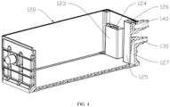
FIG. 4 is a schematic structural diagram of the casing of the battery pack in First Embodiment of the present invention. - Reference numerals:
110 refers to upper cooling pipe, 111 refers to first mounting block, 112 refers to second mounting block, 113 refers to first inserting portion, 114 refers to second inserting portion, 120 refers to casing, 121 refers to base, 122 refers to radiating rib, 123 refers to first connecting column, 124 refers to pipeline, 125 refers to second connecting column, 126 refers to groove, 127 refers to connecting channel, 128 refers to second through hole, 130 refers to water inlet pipe, 140 refers to water outlet pipe, and 150 refers to sealing ring. - The concept and the generated technical effect of the present invention are clearly and completely described hereinafter with reference to the embodiments to fully understand the objectives, the features and the effects of the present invention. Obviously, the described embodiments are only some but not all of the embodiments of the present invention, and based on the embodiments of the present invention, other embodiments obtained by those of ordinary skills in the art without going through any creative work all belong to the scope of protection of the present invention.
- In the description of the embodiments of the present invention, the orientation or position relationship indicated by the terms "up", "down", "front", "rear", "left", "right", and the like is based on the orientation or position relationship shown in the accompanying drawings, it is only for the convenience of description of the present invention and simplification of the description, and it is not to indicate or imply that the indicated device or element must have a specific orientation, and be constructed and operated in a specific orientation. Therefore, the terms should not be understood as limiting the present invention.
- In the description of the embodiments of the present invention, if some feature is described as being "set", "fixed", "connected" or "mounted" on another feature, the feature may be directly set, fixed or connected to another feature, or indirectly set, fixed, connected or mounted on another feature. In the description of the embodiments of the present invention, the meaning of "several" refers to being one or more, and the meaning of "multiple/a plurality of" refers to being two or more. The meanings of "greater than", "less than" and "more than" should all be understood as not including this number, while the meanings of "above", "below" and "within" should all be understood as including this number. The terms "first" and "second" should be understood as being used for distinguishing between the technical features only in the description, and cannot be understood as indicating or implying relative importance, implicitly indicating the number of technical features indicated thereby, or implicitly indicating the order of technical features indicated thereby.
- A battery pack according to an embodiment in a first aspect of the present invention is described hereinafter with reference to
FIG. 1 to FIG. 4 . - As shown in
FIG. 1 to FIG. 4 , the battery pack according to the embodiment in the first aspect of the present invention includes anupper cooling pipe 110, acasing 120, awater inlet pipe 130, awater outlet pipe 140 and a plurality of cells. - A first connecting
column 123 and a second connectingcolumn 125 are arranged in thecasing 120, a cooling pipeline is formed in abase 121 of thecasing 120, apipeline 124 is arranged in the first connectingcolumn 123, thepipeline 124 is arranged in a vertical direction, one end of theupper cooling pipe 110 is connected to a top portion of the first connectingcolumn 123, and is communicated with one end of the cooling pipeline through thepipeline 124, agroove 126 arranged in a vertical direction is formed on a top portion of the second connectingcolumn 125, and the other end of theupper cooling pipe 110 is connected to the top portion of the second connectingcolumn 125, and is hermetically connected with an opening of thegroove 126. An end portion of thewater inlet pipe 130 is arranged on an outer wall of thecasing 120, and thewater inlet pipe 130 is communicated with the cooling pipeline. An end portion of thewater outlet pipe 140 is arranged on the outer wall of thecasing 120, and thewater outlet pipe 140 is communicated with theupper cooling pipe 110 through thegroove 126. The plurality of cells are arranged in thecasing 120, and are located between theupper cooling pipe 110 and the cooling pipeline. - Specifically, a cooling system loop is defined by the
water inlet pipe 130, the cooling pipeline, the first connectingcolumn 123, theupper cooling pipe 110, the second connectingcolumn 125 and thewater outlet pipe 140. Thewater inlet pipe 130 is communicated with the cooling pipeline, theupper cooling pipe 110 is communicated with thewater outlet pipe 140 through thegroove 126 on the second connectingcolumn 125. Cooling liquid finishes heat adsorption to the cells through the cooling system, thus playing a role of heat dissipation. A channel between thegroove 126 in the second connectingcolumn 125 and thewater outlet pipe 140 is in an L-shape, which means that the opening of thegroove 126 is arranged in a vertical direction, so that theupper cooling pipe 110 may be directly mounted on the second connectingcolumn 125 in a vertical direction, and theupper cooling pipe 110 is communicated with thegroove 126, and the cooling liquid flows to thegroove 126 from theupper cooling pipe 110, and flows out of thewater outlet pipe 140. Since the first connectingcolumn 123 and the second connectingcolumn 125 are arranged on an inner wall of thecasing 120, and the cooling pipeline is arranged in thebase 121 of thecasing 120, if the cells located between theupper cooling pipe 110 and the cooling pipeline need to be treated, it is only necessary to detach theupper cooling pipe 110 from the first connectingcolumn 123 and the second connectingcolumn 125 to treat the cells. Thepipeline 124 in the first connectingcolumn 123 is arranged in the vertical direction, and thegroove 126 on the second connectingcolumn 125 is arranged in the vertical direction, so that the upper cooling pipe may be directly mounted on the first connectingcolumn 123 and the second connectingcolumn 125 respectively in the vertical direction, thus facilitating detachment and mounting of theupper cooling pipe 110, without detaching additional apparatuses. - In some embodiments of the present invention, a plurality of radiating
ribs 122 are arranged in the cooling pipeline, and the radiatingribs 122 are arranged at intervals in the cooling pipeline. For example, as shown inFIG. 2 andFIG. 4 , the plurality of radiatingribs 122 are arranged at intervals in the cooling pipeline. Specifically, by arranging the plurality of radiatingribs 122 at intervals in the cooling pipeline, a flowing direction of the cooling liquid is bent, so that a flowing time of the cooling liquid in the cooling pipeline is prolonged, and more heat is absorbed, thus improving the heat dissipation efficiency of the cooling pipeline. - In some embodiments of the present invention, a connecting
channel 127 is arranged in the second connectingcolumn 125, the connectingchannel 127 is located below thegroove 126, and the cooling pipeline is communicated with thewater inlet pipe 130 through the connectingchannel 127. For example, as shown inFIG. 2 andFIG. 4 , the connectingchannel 127 is arranged in the second connectingcolumn 125, the connectingchannel 127 is located below thegroove 126, and the cooling pipeline is communicated with thewater inlet pipe 130 through the connectingchannel 127. Specifically, by arranging the connectingchannel 127 below thegroove 126, and also arranging the connectingchannel 127 in the second connectingcolumn 125, thegroove 126 and the connectingchannel 127 are not communicated with each other, and thewater inlet pipe 130 is arranged at a position corresponding to the second connectingcolumn 125, so that the cooling pipeline may be communicated with thewater inlet pipe 130 through the connectingchannel 127, thus making the cooling liquid enter the cooling pipeline more quickly under an action of gravity and absorbing heat emitted by the cells on the cooling pipeline. - In some embodiments of the present invention, the
upper cooling pipe 110 and the cooling pipeline are both set to be in a U-shape. For example, as shown inFIG. 1 andFIG. 2 , theupper cooling pipe 110 and the cooling pipeline are both set to be in the U-shape. Specifically, by setting theupper cooling pipe 110 and the cooling pipeline to be in the U-shape, theupper cooling pipe 110 and the cooling pipeline may be better covered on the cells. Meanwhile, a good cooling and heat dissipation loop may be defined by the cooling pipe, the connecting columns, thewater inlet pipe 130 and thewater outlet pipe 140. In addition, by setting theupper cooling pipe 110 and the cooling pipeline to be in the U-shape, a pipe section length of theupper cooling pipe 110 and a length of the cooling pipeline can also be increased. Meanwhile, contact areas of theupper cooling pipe 110 and the cooling pipeline with the cells are increased, and a flowing time of the cooling liquid in theupper cooling pipe 110 and the cooling pipeline is prolonged, thus prolonging a heat adsorption time of the cooling liquid, and improving heat dissipation effects of the upper cooling pipe and the cooling pipeline. It is conceivable that the upper cooling pipe and the cooling pipeline may also be set to be in an S-shape, so as to increase the pipe section length of theupper cooling pipe 110 and the length of the cooling pipeline, thus improving the heat dissipation effects of theupper cooling pipe 110 and the cooling pipeline. In the embodiment, setting theupper cooling pipe 110 and the cooling pipeline to be in the U-shape is not a specific limitation to the present invention. - In some embodiments of the present invention, the
water outlet pipe 140 is located right above thewater inlet pipe 130. For example, as shown inFIG. 1 andFIG. 2 , thewater outlet pipe 140 is located right above thewater inlet pipe 130. Specifically, by arranging thewater outlet pipe 140 right above thewater inlet pipe 130, theupper cooling pipe 110 is also located above the cooling pipeline, and the cooling liquid enters from thewater inlet pipe 130, passes through the cooling pipeline, the first connectingcolumn 123 and theupper cooling pipe 110 in sequence, and then flows out of thewater outlet pipe 140, so as to form the heat dissipation loop. Meanwhile, since theupper cooling pipe 110 is integrally formed with a bottom portion of thecasing 120, which means that the upper cooling pipe is located on an innermost side of thecasing 120. When the cells are mounted in thecasing 120, heat close to the cooling pipeline is more difficult to be dissipated than heat at theupper cooling pipe 110, and the cooling liquid entering from the cooling pipeline can improve the heat dissipation effect at the cooling pipeline, thus ensuring the use efficiency of the battery pack. - In some embodiments of the present invention, two ends of the
upper cooling pipe 110 are further respectively provided with afirst mounting block 111 and asecond mounting block 112, a bottom portion of thefirst mounting block 111 is provided with a first insertingportion 113, a bottom portion of thesecond mounting block 112 is provided with a second insertingportion 114, thefirst mounting block 111 is inserted into thepipeline 124 through the first insertingportion 113, and thesecond mounting block 112 is inserted into thegroove 126 through the second inserting portion. For example, as shown inFIG. 1 andFIG. 2 , the bottom portion of thefirst mounting block 111 is provided with the first insertingportion 113, the bottom portion of thesecond mounting block 112 is provided with the second insertingportion 114, thefirst mounting block 111 is inserted into thepipeline 124 through the first insertingportion 113, and thesecond mounting block 112 is inserted into thegroove 126 through the second inserting portion. Specifically, since it is difficult to mount theupper cooling pipe 110 on the first connectingcolumn 123 and the second connectingcolumn 125, two ends of theupper cooling pipe 110 are respectively provided with thefirst mounting block 111 and thesecond mounting block 112, so that one end of theupper cooling pipe 110 may be mounted on the first connectingcolumn 123 through thefirst mounting block 111, and the other end of the upper cooling pipe may be mounted on the second connectingcolumn 125 through thesecond mounting block 112. The bottom portion of thefirst mounting block 111 is provided with the first insertingportion 113, so that thefirst mounting block 111 may be inserted into thepipeline 124 through the first insertingportion 113, thus facilitating mounting of one end of theupper cooling pipe 110 on the first connectingcolumn 123. The bottom portion of thesecond mounting block 112 is provided with the second insertingportion 114, so that thesecond mounting block 112 may be inserted into thegroove 126 through the second insertingportion 114, thus facilitating mounting of the other end of theupper cooling pipe 110 on the second connectingcolumn 125. - In some embodiments of the present invention, a first through hole is arranged in the
first mounting block 111, a second throughhole 128 is arranged in thesecond mounting block 112, the first through hole and the second throughhole 128 are both in an L-shape, a horizontal portion of the first through hole is communicated with one end of theupper cooling pipe 110, a vertical portion of the first through hole extends across the first insertingportion 113, a horizontal portion of the second throughhole 128 is communicated with the other end of theupper cooling pipe 110, and a vertical portion of the second throughhole 128 extends across the second insertingportion 114. For example, as shown inFIG. 1 , the second throughhole 128 is set to be in the L-shape, the horizontal portion of the second throughhole 128 is communicated with the other end of theupper cooling pipe 110, and the vertical portion of the second throughhole 128 extends across the second insertingportion 114. Specifically, by setting the first through hole and the second throughhole 128 to be in the L-shape, communicating the horizontal portion of the first through hole with one end of theupper cooling pipe 110, and making the vertical portion of the first through hole extend across the first insertingportion 113, the cooling liquid in the cooling pipeline can pass through the first insertingportion 113 and the first through hole in sequence and then flow into theupper cooling pipe 110. Moreover, by communicating the horizontal portion of the second throughhole 128 with the other end of theupper cooling pipe 110, and making the vertical portion of the second throughhole 128 extend across the second inserting portion, the cooling liquid in theupper cooling pipe 110 can pass through the second throughhole 128 and the second insertingportion 114 in sequence and then flow into thewater outlet pipe 140, and then flow out of thewater outlet pipe 140. Meanwhile, a plurality of connecting holes are formed in thefirst mounting block 111 and thesecond mounting block 112, a plurality of threaded holes are formed in upper surfaces of the first connectingcolumn 123 and the second connectingcolumn 125, and the connecting holes are in one-to-one correspondence with the threaded holes. Thefirst mounting block 111 is mounted on the first connectingcolumn 123 by bolt connection, and thesecond mounting block 112 is mounted on the second connectingcolumn 125 by bolt connection. An opening of the threaded hole is arranged in a vertical direction, which facilitates direct detachment or mounting of theupper cooling pipe 110 in the vertical direction. - In some embodiments of the present invention, the battery pack further includes a plurality of sealing
rings 150, wherein the sealing rings 150 are respectively arranged at a matching position between the first insertingportion 113 and thepipeline 124 and a matching position between the second insertingportion 114 and thegroove 126. For example, as shown inFIG. 2 andFIG. 3 , four sealingrings 150 are arranged at the matching position between the second insertingportion 114 and thegroove 126. Specifically, by arranging four sealingrings 150 at the matching position between the first insertingportion 113 and thepipeline 124 and the matching position between the second insertingportion 114 and thegroove 126 respectively, the first insertingportion 113 can be matched with thepipeline 124 more stably, so that thefirst mounting block 111 at one end of theupper cooling pipe 110 may be mounted on the first connectingcolumn 123 more stably. Moreover, the second insertingportion 114 may be matched with thegroove 126 more stably, so that thesecond mounting block 112 at the other end of theupper cooling pipe 110 may be mounted on the second connectingcolumn 125 more stably, thus ensuring the sealing effect of the cooling loop. - In some embodiments of the present invention, one end of the
upper cooling pipe 110 is bent upwardly to be in an S-shape, and is connected with thesecond mounting block 112. For example, as shown inFIG. 1 andFIG. 2 , one end of theupper cooling pipe 110 is bent upwardly to be in the S-shape, and is connected with thesecond mounting block 112. Specifically, since theupper cooling pipe 110 needs to contact with the plurality of cells after mounting, there is a requirement on a mounting position of theupper cooling pipe 110. In the embodiment, the top portions of thewater outlet pipe 140 and the second connectingcolumn 125 are both located above theupper cooling pipe 110, so that theupper cooling pipe 110 needs to be bent upwardly to be in the S-shape so as to be connected with thesecond mounting block 112, and is mounted above the second connectingcolumn 125 through thesecond mounting block 112. - It can be understood that, according to actual needs, in other embodiments, if the
water outlet pipe 140 and the top portion of the second connectingcolumn 125 correspond to the position of theupper cooling pipe 110, theupper cooling pipe 110 may also be directly connected with thesecond mounting block 112, and mounted above the second connectingcolumn 125 through thesecond mounting block 112. Therefore, bending one end of theupper cooling pipe 110 upwardly to be in the S-shape is not a specific limitation to the present invention. - An automobile according to an embodiment in a second aspect of the present invention includes the battery pack according to the embodiment in the first aspect of the present invention.
- The automobile according to the embodiment in the second aspect of the present invention is driven to run by the battery pack above. The cooling system loop is defined by the
water inlet pipe 130, the cooling pipeline, the first connectingcolumn 123, theupper cooling pipe 110, the second connectingcolumn 125 and thewater outlet pipe 140 in the battery pack, and the cooling pipeline, the first connectingcolumn 123 and the second connectingcolumn 125 are all arranged on thecasing 120, the end portions of thewater inlet pipe 130 and thewater outlet pipe 140 are arranged on an outer side of thecasing 120. The cells are arranged in thecasing 120, and are located between theupper cooling pipe 110 and the cooling pipeline. In this way, if the cells need to be operated, theupper cooling pipe 110 may be directly detached for the operation, and theupper cooling pipe 110 may be directly detached and mounted in a vertical direction, thus being convenient and quick to operate, and facilitating maintenance of the battery pack, so that the automobile employing the battery pack has a longer endurance mileage and a service life of the automobile is prolonged. - The embodiments of the present invention are described in detail with reference to the drawings above, but the present invention is not limited to the above embodiments, and various changes may also be made within the knowledge scope of those of ordinary skills in the art without departing from the purpose of the present invention. In addition, the embodiments of the present invention and the features in the embodiments may be combined with each other without conflict.
Claims (10)
- A battery pack, comprising:an upper cooling pipe;a casing, wherein a first connecting column and a second connecting column are arranged in the casing, a cooling pipeline is formed in a base of the casing, a pipeline is arranged in the first connecting column, the pipeline is arranged in a vertical direction, one end of the upper cooling pipe is connected to a top portion of the first connecting column, and is communicated with one end of the cooling pipeline through the pipeline, a groove arranged in a vertical direction is formed on a top portion of the second connecting column, and the other end of the upper cooling pipe is connected to the top portion of the second connecting column, and is hermetically connected with an opening of the groove;a water inlet pipe, wherein the water inlet pipe is arranged on an outer wall of the casing, and the water inlet pipe is communicated with the cooling pipeline;a water outlet pipe, wherein the water outlet pipe is arranged on the outer wall of the casing, and the water outlet pipe is communicated with the upper cooling pipe through the groove; anda plurality of cells, wherein the plurality of cells are arranged in the casing, and are located between the upper cooling pipe and the cooling pipeline.
- The battery pack according to claim 1, wherein a plurality of radiating ribs are arranged in the cooling pipeline, and the radiating ribs are arranged at intervals in the cooling pipeline.
- The battery pack according to claim 1, wherein a connecting channel is arranged in the second connecting column, the connecting channel is located below the groove, and the cooling pipeline is communicated with the water inlet pipe through the connecting channel.
- The battery pack according to claim 1, wherein the upper cooling pipe and the cooling pipeline are both set to be in a U-shape.
- The battery pack according to claim 1, wherein the water outlet pipe is located right above the water inlet pipe.
- The battery pack according to claim 1, wherein two ends of the upper cooling pipe are further respectively provided with a first mounting block and a second mounting block, a bottom portion of the first mounting block is provided with a first inserting portion, a bottom portion of the second mounting block is provided with a second inserting portion, the first mounting block is inserted into the pipeline through the first inserting portion, and the second mounting block is inserted into the groove through the second inserting portion.
- The battery pack according to claim 6, wherein a first through hole is arranged in the first mounting block, a second through hole is arranged in the second mounting block, the first through hole and the second through hole are both in an L-shape, a horizontal portion of the first through hole is communicated with one end of the upper cooling pipe, a vertical portion of the first through hole extends across the first inserting portion, a horizontal portion of the second through hole is communicated with the other end of the upper cooling pipe, and a vertical portion of the second through hole extends across the second inserting portion.
- The battery pack according to claim 6, further comprising a plurality of sealing rings, wherein the sealing rings are respectively arranged at a matching position between the first inserting portion and the pipeline and a matching position between the second inserting portion and the groove.
- The battery pack according to claim 6, wherein one end of the upper cooling pipe is bent upwardly to be in an S-shape, and is connected with the second mounting block.
- An automobile, comprising the battery pack according to any one of claims 1 to 9.
Applications Claiming Priority (3)
| Application Number | Priority Date | Filing Date | Title |
|---|---|---|---|
| CN202010921347.5A CN112072207B (en) | 2020-09-04 | 2020-09-04 | Battery pack and vehicle |
| CN202021921823.5U CN212750985U (en) | 2020-09-04 | 2020-09-04 | Battery pack and automobile with same |
| PCT/CN2021/104013 WO2022048294A1 (en) | 2020-09-04 | 2021-07-01 | Battery pack and automobile having same |
Publications (2)
| Publication Number | Publication Date |
|---|---|
| EP4191749A1 true EP4191749A1 (en) | 2023-06-07 |
| EP4191749A4 EP4191749A4 (en) | 2024-10-16 |
Family
ID=80491603
Family Applications (1)
| Application Number | Title | Priority Date | Filing Date |
|---|---|---|---|
| EP21863362.6A Pending EP4191749A4 (en) | 2020-09-04 | 2021-07-01 | BATTERY PACK AND AUTOMOBILE COMPRISING IT |
Country Status (3)
| Country | Link |
|---|---|
| EP (1) | EP4191749A4 (en) |
| JP (1) | JP7574415B2 (en) |
| WO (1) | WO2022048294A1 (en) |
Cited By (1)
| Publication number | Priority date | Publication date | Assignee | Title |
|---|---|---|---|---|
| EP4517930A1 (en) * | 2023-07-21 | 2025-03-05 | Samsung Sdi Co., Ltd. | Battery pack |
Families Citing this family (1)
| Publication number | Priority date | Publication date | Assignee | Title |
|---|---|---|---|---|
| CN117393908B (en) * | 2023-11-30 | 2024-08-13 | 云南工商学院 | Thermal management device for new energy automobile battery |
Family Cites Families (19)
| Publication number | Priority date | Publication date | Assignee | Title |
|---|---|---|---|---|
| JP5656706B2 (en) * | 2011-03-22 | 2015-01-21 | 株式会社豊田自動織機 | Battery temperature control device |
| KR101983391B1 (en) * | 2012-11-13 | 2019-05-28 | 에스케이이노베이션 주식회사 | Cooling Device for Battery Module and Battery Module Assembly having the same |
| CN104993189B (en) * | 2015-07-22 | 2018-09-18 | 贵州大学 | A kind of heat management structure of lithium battery group liquid cooling |
| CN205752451U (en) * | 2016-06-27 | 2016-11-30 | 华霆(合肥)动力技术有限公司 | A kind of liquid cold flat tube attachment structure |
| CN106450568B (en) * | 2016-10-09 | 2019-07-02 | 浙江吉利控股集团有限公司 | A power battery pack thermal management system |
| CN207009603U (en) * | 2017-06-27 | 2018-02-13 | 安徽江淮汽车集团股份有限公司 | A kind of cold pipe connection of polylinker liquid |
| JP6992411B2 (en) * | 2017-11-01 | 2022-01-13 | 株式会社デンソー | Equipment cooling device |
| CN208298881U (en) * | 2018-02-08 | 2018-12-28 | 比亚迪股份有限公司 | Power battery pack and vehicle |
| KR102655349B1 (en) * | 2018-06-28 | 2024-04-05 | 에스케이온 주식회사 | Battery pack having cooling device |
| JP6683779B2 (en) * | 2018-08-31 | 2020-04-22 | 本田技研工業株式会社 | Battery pack cooling structure |
| KR102204302B1 (en) * | 2018-09-13 | 2021-01-15 | 주식회사 엘지화학 | Battery module, battery pack comprising the battery module and vehicle comprising the battery pack |
| CN208738329U (en) * | 2018-09-21 | 2019-04-12 | 宁德时代新能源科技股份有限公司 | a battery pack |
| CN109473577A (en) * | 2018-12-27 | 2019-03-15 | 风帆有限责任公司 | A shell of a lithium-ion battery module with good heat dissipation effect |
| US20200251698A1 (en) * | 2019-01-31 | 2020-08-06 | Ford Global Technologies, Llc | Multi-tiered battery pack and liquid coolant communication method for same |
| CN209843771U (en) * | 2019-04-24 | 2019-12-24 | 浙江吉利控股集团有限公司 | A battery module |
| CN210866422U (en) * | 2019-11-13 | 2020-06-26 | 欣旺达电动汽车电池有限公司 | 48V start-stop power supply and electric vehicle |
| CN212750985U (en) * | 2020-09-04 | 2021-03-19 | 欣旺达惠州动力新能源有限公司 | Battery pack and automobile with same |
| CN112072207B (en) * | 2020-09-04 | 2025-02-18 | 欣旺达惠州动力新能源有限公司 | Battery pack and vehicle |
| CN213124557U (en) * | 2020-09-04 | 2021-05-04 | 欣旺达惠州动力新能源有限公司 | Cooling device, battery pack and automobile with battery pack |
-
2021
- 2021-07-01 JP JP2023513756A patent/JP7574415B2/en active Active
- 2021-07-01 WO PCT/CN2021/104013 patent/WO2022048294A1/en not_active Ceased
- 2021-07-01 EP EP21863362.6A patent/EP4191749A4/en active Pending
Cited By (1)
| Publication number | Priority date | Publication date | Assignee | Title |
|---|---|---|---|---|
| EP4517930A1 (en) * | 2023-07-21 | 2025-03-05 | Samsung Sdi Co., Ltd. | Battery pack |
Also Published As
| Publication number | Publication date |
|---|---|
| JP7574415B2 (en) | 2024-10-28 |
| EP4191749A4 (en) | 2024-10-16 |
| WO2022048294A1 (en) | 2022-03-10 |
| JP2023548731A (en) | 2023-11-21 |
Similar Documents
| Publication | Publication Date | Title |
|---|---|---|
| CN110891399B (en) | Heat dissipation device for new energy vehicle charging pile power supply | |
| CN112072207B (en) | Battery pack and vehicle | |
| JP7574415B2 (en) | Battery packs and automobiles | |
| CN212750985U (en) | Battery pack and automobile with same | |
| US11311905B2 (en) | Ultraviolet curing device and control method thereof | |
| CN209879421U (en) | Server equipment and server devices based on the HGX platform | |
| CN209730028U (en) | A kind of new-energy automobile power battery structure | |
| CN220983845U (en) | Heat abstractor and server | |
| CN118843297A (en) | Liquid supply device and closed liquid cooling system | |
| CN219041642U (en) | Photovoltaic inverter with heat dissipation and noise reduction functions | |
| CN219592965U (en) | Heat abstractor and ore deposit machine | |
| CN219421423U (en) | Heat dissipation structure and power supply unit | |
| CN218547892U (en) | Liquid crystal display module with water-cooling heat dissipation function | |
| US12191624B2 (en) | Cooling system for laser | |
| CN118281396A (en) | Battery assembly of vehicle, vehicle body assembly and vehicle | |
| CN112687983B (en) | Two heat dissipation formula new forms of energy battery fixed cases | |
| CN210835956U (en) | Water cooling mechanism for CPU | |
| CN210241752U (en) | Splicable radiating fin structure | |
| CN222749646U (en) | Battery devices and power-consuming devices | |
| CN220306375U (en) | Battery module installation shell | |
| CN218241991U (en) | Cooling structure of LED driving power supply | |
| US20250324543A1 (en) | Water-cooling radiator for graphics card | |
| CN214822480U (en) | Water-cooled automobile refrigeration unit | |
| CN223207433U (en) | Compact type on-line nuclear capacity device heat dissipation air duct structure | |
| CN219843030U (en) | Liquid cooling heat dissipation system and engineering machinery |
Legal Events
| Date | Code | Title | Description |
|---|---|---|---|
| STAA | Information on the status of an ep patent application or granted ep patent |
Free format text: STATUS: THE INTERNATIONAL PUBLICATION HAS BEEN MADE |
|
| PUAI | Public reference made under article 153(3) epc to a published international application that has entered the european phase |
Free format text: ORIGINAL CODE: 0009012 |
|
| STAA | Information on the status of an ep patent application or granted ep patent |
Free format text: STATUS: REQUEST FOR EXAMINATION WAS MADE |
|
| 17P | Request for examination filed |
Effective date: 20230301 |
|
| AK | Designated contracting states |
Kind code of ref document: A1 Designated state(s): AL AT BE BG CH CY CZ DE DK EE ES FI FR GB GR HR HU IE IS IT LI LT LU LV MC MK MT NL NO PL PT RO RS SE SI SK SM TR |
|
| DAV | Request for validation of the european patent (deleted) | ||
| DAX | Request for extension of the european patent (deleted) | ||
| RAP3 | Party data changed (applicant data changed or rights of an application transferred) |
Owner name: SUNWODA MOBILITY ENERGY TECHNOLOGY CO., LTD. |
|
| A4 | Supplementary search report drawn up and despatched |
Effective date: 20240917 |
|
| RIC1 | Information provided on ipc code assigned before grant |
Ipc: H01M 10/6568 20140101ALI20240911BHEP Ipc: H01M 10/613 20140101AFI20240911BHEP |