EP4191695A1 - Display device - Google Patents
Display device Download PDFInfo
- Publication number
- EP4191695A1 EP4191695A1 EP20947376.8A EP20947376A EP4191695A1 EP 4191695 A1 EP4191695 A1 EP 4191695A1 EP 20947376 A EP20947376 A EP 20947376A EP 4191695 A1 EP4191695 A1 EP 4191695A1
- Authority
- EP
- European Patent Office
- Prior art keywords
- pattern
- optical pattern
- emission area
- display device
- light
- Prior art date
- Legal status (The legal status is an assumption and is not a legal conclusion. Google has not performed a legal analysis and makes no representation as to the accuracy of the status listed.)
- Pending
Links
- 230000003287 optical effect Effects 0.000 claims abstract description 358
- 238000006243 chemical reaction Methods 0.000 claims abstract description 208
- 239000010409 thin film Substances 0.000 claims abstract description 38
- 238000005538 encapsulation Methods 0.000 claims abstract description 37
- 239000000463 material Substances 0.000 claims description 98
- 239000000945 filler Substances 0.000 claims description 65
- 125000006850 spacer group Chemical group 0.000 claims description 64
- 229920005989 resin Polymers 0.000 claims description 54
- 239000011347 resin Substances 0.000 claims description 54
- 230000005540 biological transmission Effects 0.000 claims description 48
- 239000002245 particle Substances 0.000 claims description 33
- 229910010272 inorganic material Inorganic materials 0.000 claims description 10
- 239000011147 inorganic material Substances 0.000 claims description 10
- 230000007423 decrease Effects 0.000 claims description 7
- 239000010410 layer Substances 0.000 description 451
- 239000000758 substrate Substances 0.000 description 123
- 230000005525 hole transport Effects 0.000 description 34
- 150000001875 compounds Chemical class 0.000 description 33
- 102100027126 Echinoderm microtubule-associated protein-like 2 Human genes 0.000 description 30
- 101001057942 Homo sapiens Echinoderm microtubule-associated protein-like 2 Proteins 0.000 description 30
- 102100027095 Echinoderm microtubule-associated protein-like 3 Human genes 0.000 description 27
- 101001057939 Homo sapiens Echinoderm microtubule-associated protein-like 3 Proteins 0.000 description 27
- 102100027094 Echinoderm microtubule-associated protein-like 1 Human genes 0.000 description 24
- 101001057941 Homo sapiens Echinoderm microtubule-associated protein-like 1 Proteins 0.000 description 24
- 238000000034 method Methods 0.000 description 20
- 239000000203 mixture Substances 0.000 description 20
- 239000011368 organic material Substances 0.000 description 20
- 230000000903 blocking effect Effects 0.000 description 19
- 102100030385 Granzyme B Human genes 0.000 description 17
- 101001009603 Homo sapiens Granzyme B Proteins 0.000 description 17
- 201000001130 congenital generalized lipodystrophy type 1 Diseases 0.000 description 17
- 239000002096 quantum dot Substances 0.000 description 17
- 238000002347 injection Methods 0.000 description 15
- 239000007924 injection Substances 0.000 description 15
- 101100451713 Saccharomyces cerevisiae (strain ATCC 204508 / S288c) HTL1 gene Proteins 0.000 description 13
- -1 polyphenylene Polymers 0.000 description 13
- 230000008569 process Effects 0.000 description 13
- 230000001965 increasing effect Effects 0.000 description 11
- 238000007789 sealing Methods 0.000 description 10
- 239000002356 single layer Substances 0.000 description 9
- TVIVIEFSHFOWTE-UHFFFAOYSA-K tri(quinolin-8-yloxy)alumane Chemical compound [Al+3].C1=CN=C2C([O-])=CC=CC2=C1.C1=CN=C2C([O-])=CC=CC2=C1.C1=CN=C2C([O-])=CC=CC2=C1 TVIVIEFSHFOWTE-UHFFFAOYSA-K 0.000 description 9
- 102100027100 Echinoderm microtubule-associated protein-like 4 Human genes 0.000 description 8
- 101001057929 Homo sapiens Echinoderm microtubule-associated protein-like 4 Proteins 0.000 description 8
- VYPSYNLAJGMNEJ-UHFFFAOYSA-N Silicium dioxide Chemical compound O=[Si]=O VYPSYNLAJGMNEJ-UHFFFAOYSA-N 0.000 description 8
- PQXKHYXIUOZZFA-UHFFFAOYSA-M lithium fluoride Chemical compound [Li+].[F-] PQXKHYXIUOZZFA-UHFFFAOYSA-M 0.000 description 8
- 239000012044 organic layer Substances 0.000 description 8
- 229920000178 Acrylic resin Polymers 0.000 description 7
- 239000004925 Acrylic resin Substances 0.000 description 7
- XLOMVQKBTHCTTD-UHFFFAOYSA-N Zinc monoxide Chemical compound [Zn]=O XLOMVQKBTHCTTD-UHFFFAOYSA-N 0.000 description 7
- 230000008901 benefit Effects 0.000 description 7
- 201000001379 familial temporal lobe epilepsy 3 Diseases 0.000 description 7
- 239000002861 polymer material Substances 0.000 description 7
- AWXGSYPUMWKTBR-UHFFFAOYSA-N 4-carbazol-9-yl-n,n-bis(4-carbazol-9-ylphenyl)aniline Chemical compound C12=CC=CC=C2C2=CC=CC=C2N1C1=CC=C(N(C=2C=CC(=CC=2)N2C3=CC=CC=C3C3=CC=CC=C32)C=2C=CC(=CC=2)N2C3=CC=CC=C3C3=CC=CC=C32)C=C1 AWXGSYPUMWKTBR-UHFFFAOYSA-N 0.000 description 6
- GWEVSGVZZGPLCZ-UHFFFAOYSA-N Titan oxide Chemical compound O=[Ti]=O GWEVSGVZZGPLCZ-UHFFFAOYSA-N 0.000 description 6
- 229910052782 aluminium Inorganic materials 0.000 description 6
- 150000003949 imides Chemical class 0.000 description 6
- 229920000642 polymer Polymers 0.000 description 6
- VFUDMQLBKNMONU-UHFFFAOYSA-N 9-[4-(4-carbazol-9-ylphenyl)phenyl]carbazole Chemical group C12=CC=CC=C2C2=CC=CC=C2N1C1=CC=C(C=2C=CC(=CC=2)N2C3=CC=CC=C3C3=CC=CC=C32)C=C1 VFUDMQLBKNMONU-UHFFFAOYSA-N 0.000 description 5
- 101150020392 Cgl3 gene Proteins 0.000 description 5
- 239000007983 Tris buffer Substances 0.000 description 5
- 201000001113 congenital generalized lipodystrophy type 3 Diseases 0.000 description 5
- 229910052751 metal Inorganic materials 0.000 description 5
- 239000002184 metal Substances 0.000 description 5
- 150000004706 metal oxides Chemical class 0.000 description 5
- 239000002159 nanocrystal Substances 0.000 description 5
- TWNQGVIAIRXVLR-UHFFFAOYSA-N oxo(oxoalumanyloxy)alumane Chemical compound O=[Al]O[Al]=O TWNQGVIAIRXVLR-UHFFFAOYSA-N 0.000 description 5
- 229920003227 poly(N-vinyl carbazole) Polymers 0.000 description 5
- 229910052709 silver Inorganic materials 0.000 description 5
- XOLBLPGZBRYERU-UHFFFAOYSA-N tin dioxide Chemical compound O=[Sn]=O XOLBLPGZBRYERU-UHFFFAOYSA-N 0.000 description 5
- HNWFFTUWRIGBNM-UHFFFAOYSA-N 2-methyl-9,10-dinaphthalen-2-ylanthracene Chemical compound C1=CC=CC2=CC(C3=C4C=CC=CC4=C(C=4C=C5C=CC=CC5=CC=4)C4=CC=C(C=C43)C)=CC=C21 HNWFFTUWRIGBNM-UHFFFAOYSA-N 0.000 description 4
- OBAJPWYDYFEBTF-UHFFFAOYSA-N 2-tert-butyl-9,10-dinaphthalen-2-ylanthracene Chemical compound C1=CC=CC2=CC(C3=C4C=CC=CC4=C(C=4C=C5C=CC=CC5=CC=4)C4=CC=C(C=C43)C(C)(C)C)=CC=C21 OBAJPWYDYFEBTF-UHFFFAOYSA-N 0.000 description 4
- ZVFQEOPUXVPSLB-UHFFFAOYSA-N 3-(4-tert-butylphenyl)-4-phenyl-5-(4-phenylphenyl)-1,2,4-triazole Chemical compound C1=CC(C(C)(C)C)=CC=C1C(N1C=2C=CC=CC=2)=NN=C1C1=CC=C(C=2C=CC=CC=2)C=C1 ZVFQEOPUXVPSLB-UHFFFAOYSA-N 0.000 description 4
- LTUJKAYZIMMJEP-UHFFFAOYSA-N 9-[4-(4-carbazol-9-yl-2-methylphenyl)-3-methylphenyl]carbazole Chemical group C12=CC=CC=C2C2=CC=CC=C2N1C1=CC=C(C=2C(=CC(=CC=2)N2C3=CC=CC=C3C3=CC=CC=C32)C)C(C)=C1 LTUJKAYZIMMJEP-UHFFFAOYSA-N 0.000 description 4
- 101100128100 Arabidopsis thaliana LFG2 gene Proteins 0.000 description 4
- 101000837344 Homo sapiens T-cell leukemia translocation-altered gene protein Proteins 0.000 description 4
- UQSXHKLRYXJYBZ-UHFFFAOYSA-N Iron oxide Chemical compound [Fe]=O UQSXHKLRYXJYBZ-UHFFFAOYSA-N 0.000 description 4
- 102100028692 T-cell leukemia translocation-altered gene protein Human genes 0.000 description 4
- 230000008033 biological extinction Effects 0.000 description 4
- 239000003822 epoxy resin Substances 0.000 description 4
- 229910052731 fluorine Inorganic materials 0.000 description 4
- 125000001153 fluoro group Chemical group F* 0.000 description 4
- 239000011521 glass Substances 0.000 description 4
- 229910052746 lanthanum Inorganic materials 0.000 description 4
- FZLIPJUXYLNCLC-UHFFFAOYSA-N lanthanum atom Chemical compound [La] FZLIPJUXYLNCLC-UHFFFAOYSA-N 0.000 description 4
- 239000011777 magnesium Substances 0.000 description 4
- 238000004519 manufacturing process Methods 0.000 description 4
- 229910001507 metal halide Inorganic materials 0.000 description 4
- 229920003023 plastic Polymers 0.000 description 4
- 239000004033 plastic Substances 0.000 description 4
- 229920000647 polyepoxide Polymers 0.000 description 4
- 229920002803 thermoplastic polyurethane Polymers 0.000 description 4
- 238000002834 transmittance Methods 0.000 description 4
- GEQBRULPNIVQPP-UHFFFAOYSA-N 2-[3,5-bis(1-phenylbenzimidazol-2-yl)phenyl]-1-phenylbenzimidazole Chemical compound C1=CC=CC=C1N1C2=CC=CC=C2N=C1C1=CC(C=2N(C3=CC=CC=C3N=2)C=2C=CC=CC=2)=CC(C=2N(C3=CC=CC=C3N=2)C=2C=CC=CC=2)=C1 GEQBRULPNIVQPP-UHFFFAOYSA-N 0.000 description 3
- VQGHOUODWALEFC-UHFFFAOYSA-N 2-phenylpyridine Chemical compound C1=CC=CC=C1C1=CC=CC=N1 VQGHOUODWALEFC-UHFFFAOYSA-N 0.000 description 3
- VIZUPBYFLORCRA-UHFFFAOYSA-N 9,10-dinaphthalen-2-ylanthracene Chemical compound C12=CC=CC=C2C(C2=CC3=CC=CC=C3C=C2)=C(C=CC=C2)C2=C1C1=CC=C(C=CC=C2)C2=C1 VIZUPBYFLORCRA-UHFFFAOYSA-N 0.000 description 3
- 239000004593 Epoxy Substances 0.000 description 3
- 101100232347 Mus musculus Il11ra1 gene Proteins 0.000 description 3
- XAGFODPZIPBFFR-UHFFFAOYSA-N aluminium Chemical compound [Al] XAGFODPZIPBFFR-UHFFFAOYSA-N 0.000 description 3
- 238000000149 argon plasma sintering Methods 0.000 description 3
- UFVXQDWNSAGPHN-UHFFFAOYSA-K bis[(2-methylquinolin-8-yl)oxy]-(4-phenylphenoxy)alumane Chemical compound [Al+3].C1=CC=C([O-])C2=NC(C)=CC=C21.C1=CC=C([O-])C2=NC(C)=CC=C21.C1=CC([O-])=CC=C1C1=CC=CC=C1 UFVXQDWNSAGPHN-UHFFFAOYSA-K 0.000 description 3
- 239000000038 blue colorant Substances 0.000 description 3
- 239000002019 doping agent Substances 0.000 description 3
- 230000000694 effects Effects 0.000 description 3
- 201000001366 familial temporal lobe epilepsy 2 Diseases 0.000 description 3
- 229910052749 magnesium Inorganic materials 0.000 description 3
- 150000005309 metal halides Chemical class 0.000 description 3
- 229910044991 metal oxide Inorganic materials 0.000 description 3
- 239000004065 semiconductor Substances 0.000 description 3
- 229910052710 silicon Inorganic materials 0.000 description 3
- 239000000377 silicon dioxide Substances 0.000 description 3
- 229910001887 tin oxide Inorganic materials 0.000 description 3
- OGIDPMRJRNCKJF-UHFFFAOYSA-N titanium oxide Inorganic materials [Ti]=O OGIDPMRJRNCKJF-UHFFFAOYSA-N 0.000 description 3
- ODHXBMXNKOYIBV-UHFFFAOYSA-N triphenylamine Chemical compound C1=CC=CC=C1N(C=1C=CC=CC=1)C1=CC=CC=C1 ODHXBMXNKOYIBV-UHFFFAOYSA-N 0.000 description 3
- NGQSLSMAEVWNPU-YTEMWHBBSA-N 1,2-bis[(e)-2-phenylethenyl]benzene Chemical compound C=1C=CC=CC=1/C=C/C1=CC=CC=C1\C=C\C1=CC=CC=C1 NGQSLSMAEVWNPU-YTEMWHBBSA-N 0.000 description 2
- OGGKVJMNFFSDEV-UHFFFAOYSA-N 3-methyl-n-[4-[4-(n-(3-methylphenyl)anilino)phenyl]phenyl]-n-phenylaniline Chemical compound CC1=CC=CC(N(C=2C=CC=CC=2)C=2C=CC(=CC=2)C=2C=CC(=CC=2)N(C=2C=CC=CC=2)C=2C=C(C)C=CC=2)=C1 OGGKVJMNFFSDEV-UHFFFAOYSA-N 0.000 description 2
- ZOKIJILZFXPFTO-UHFFFAOYSA-N 4-methyl-n-[4-[1-[4-(4-methyl-n-(4-methylphenyl)anilino)phenyl]cyclohexyl]phenyl]-n-(4-methylphenyl)aniline Chemical compound C1=CC(C)=CC=C1N(C=1C=CC(=CC=1)C1(CCCCC1)C=1C=CC(=CC=1)N(C=1C=CC(C)=CC=1)C=1C=CC(C)=CC=1)C1=CC=C(C)C=C1 ZOKIJILZFXPFTO-UHFFFAOYSA-N 0.000 description 2
- AOQKGYRILLEVJV-UHFFFAOYSA-N 4-naphthalen-1-yl-3,5-diphenyl-1,2,4-triazole Chemical compound C1=CC=CC=C1C(N1C=2C3=CC=CC=C3C=CC=2)=NN=C1C1=CC=CC=C1 AOQKGYRILLEVJV-UHFFFAOYSA-N 0.000 description 2
- UJOBWOGCFQCDNV-UHFFFAOYSA-N 9H-carbazole Chemical compound C1=CC=C2C3=CC=CC=C3NC2=C1 UJOBWOGCFQCDNV-UHFFFAOYSA-N 0.000 description 2
- 229910017115 AlSb Inorganic materials 0.000 description 2
- 229910004613 CdTe Inorganic materials 0.000 description 2
- QPLDLSVMHZLSFG-UHFFFAOYSA-N Copper oxide Chemical compound [Cu]=O QPLDLSVMHZLSFG-UHFFFAOYSA-N 0.000 description 2
- JOYRKODLDBILNP-UHFFFAOYSA-N Ethyl urethane Chemical compound CCOC(N)=O JOYRKODLDBILNP-UHFFFAOYSA-N 0.000 description 2
- 229910005540 GaP Inorganic materials 0.000 description 2
- 229910005542 GaSb Inorganic materials 0.000 description 2
- 229910001218 Gallium arsenide Inorganic materials 0.000 description 2
- 229910004262 HgTe Inorganic materials 0.000 description 2
- 229910000673 Indium arsenide Inorganic materials 0.000 description 2
- 229910052779 Neodymium Inorganic materials 0.000 description 2
- OAICVXFJPJFONN-UHFFFAOYSA-N Phosphorus Chemical compound [P] OAICVXFJPJFONN-UHFFFAOYSA-N 0.000 description 2
- 206010034972 Photosensitivity reaction Diseases 0.000 description 2
- 229910052581 Si3N4 Inorganic materials 0.000 description 2
- XUIMIQQOPSSXEZ-UHFFFAOYSA-N Silicon Chemical compound [Si] XUIMIQQOPSSXEZ-UHFFFAOYSA-N 0.000 description 2
- NRTOMJZYCJJWKI-UHFFFAOYSA-N Titanium nitride Chemical compound [Ti]#N NRTOMJZYCJJWKI-UHFFFAOYSA-N 0.000 description 2
- 229910007709 ZnTe Inorganic materials 0.000 description 2
- UMIVXZPTRXBADB-UHFFFAOYSA-N benzocyclobutene Chemical compound C1=CC=C2CCC2=C1 UMIVXZPTRXBADB-UHFFFAOYSA-N 0.000 description 2
- UHYPYGJEEGLRJD-UHFFFAOYSA-N cadmium(2+);selenium(2-) Chemical compound [Se-2].[Cd+2] UHYPYGJEEGLRJD-UHFFFAOYSA-N 0.000 description 2
- 229910000420 cerium oxide Inorganic materials 0.000 description 2
- 229910052956 cinnabar Inorganic materials 0.000 description 2
- 239000003086 colorant Substances 0.000 description 2
- 239000000470 constituent Substances 0.000 description 2
- 238000011109 contamination Methods 0.000 description 2
- PMHQVHHXPFUNSP-UHFFFAOYSA-M copper(1+);methylsulfanylmethane;bromide Chemical compound Br[Cu].CSC PMHQVHHXPFUNSP-UHFFFAOYSA-M 0.000 description 2
- NIHNNTQXNPWCJQ-UHFFFAOYSA-N fluorene Chemical compound C1=CC=C2CC3=CC=CC=C3C2=C1 NIHNNTQXNPWCJQ-UHFFFAOYSA-N 0.000 description 2
- 229910052737 gold Inorganic materials 0.000 description 2
- 229910052735 hafnium Inorganic materials 0.000 description 2
- 239000012535 impurity Substances 0.000 description 2
- WPYVAWXEWQSOGY-UHFFFAOYSA-N indium antimonide Chemical compound [Sb]#[In] WPYVAWXEWQSOGY-UHFFFAOYSA-N 0.000 description 2
- RPQDHPTXJYYUPQ-UHFFFAOYSA-N indium arsenide Chemical compound [In]#[As] RPQDHPTXJYYUPQ-UHFFFAOYSA-N 0.000 description 2
- 229910003437 indium oxide Inorganic materials 0.000 description 2
- PJXISJQVUVHSOJ-UHFFFAOYSA-N indium(iii) oxide Chemical compound [O-2].[O-2].[O-2].[In+3].[In+3] PJXISJQVUVHSOJ-UHFFFAOYSA-N 0.000 description 2
- 230000008595 infiltration Effects 0.000 description 2
- 238000001764 infiltration Methods 0.000 description 2
- 239000010954 inorganic particle Substances 0.000 description 2
- 229910052741 iridium Inorganic materials 0.000 description 2
- 125000000040 m-tolyl group Chemical group [H]C1=C([H])C(*)=C([H])C(=C1[H])C([H])([H])[H] 0.000 description 2
- ORUIBWPALBXDOA-UHFFFAOYSA-L magnesium fluoride Chemical compound [F-].[F-].[Mg+2] ORUIBWPALBXDOA-UHFFFAOYSA-L 0.000 description 2
- 239000000395 magnesium oxide Substances 0.000 description 2
- CPLXHLVBOLITMK-UHFFFAOYSA-N magnesium oxide Inorganic materials [Mg]=O CPLXHLVBOLITMK-UHFFFAOYSA-N 0.000 description 2
- AXZKOIWUVFPNLO-UHFFFAOYSA-N magnesium;oxygen(2-) Chemical compound [O-2].[Mg+2] AXZKOIWUVFPNLO-UHFFFAOYSA-N 0.000 description 2
- 229910052759 nickel Inorganic materials 0.000 description 2
- 229910052755 nonmetal Inorganic materials 0.000 description 2
- 239000011146 organic particle Substances 0.000 description 2
- BMMGVYCKOGBVEV-UHFFFAOYSA-N oxo(oxoceriooxy)cerium Chemical compound [Ce]=O.O=[Ce]=O BMMGVYCKOGBVEV-UHFFFAOYSA-N 0.000 description 2
- RVTZCBVAJQQJTK-UHFFFAOYSA-N oxygen(2-);zirconium(4+) Chemical compound [O-2].[O-2].[Zr+4] RVTZCBVAJQQJTK-UHFFFAOYSA-N 0.000 description 2
- 229910052763 palladium Inorganic materials 0.000 description 2
- 235000012736 patent blue V Nutrition 0.000 description 2
- 229920002120 photoresistant polymer Polymers 0.000 description 2
- 230000036211 photosensitivity Effects 0.000 description 2
- 229910052697 platinum Inorganic materials 0.000 description 2
- 229920000553 poly(phenylenevinylene) Polymers 0.000 description 2
- 229920000058 polyacrylate Polymers 0.000 description 2
- 229920000767 polyaniline Polymers 0.000 description 2
- 229920002098 polyfluorene Polymers 0.000 description 2
- 229920001296 polysiloxane Polymers 0.000 description 2
- SBIBMFFZSBJNJF-UHFFFAOYSA-N selenium;zinc Chemical compound [Se]=[Zn] SBIBMFFZSBJNJF-UHFFFAOYSA-N 0.000 description 2
- 239000004054 semiconductor nanocrystal Substances 0.000 description 2
- 239000010703 silicon Substances 0.000 description 2
- HQVNEWCFYHHQES-UHFFFAOYSA-N silicon nitride Chemical compound N12[Si]34N5[Si]62N3[Si]51N64 HQVNEWCFYHHQES-UHFFFAOYSA-N 0.000 description 2
- 229910052814 silicon oxide Inorganic materials 0.000 description 2
- 229920005573 silicon-containing polymer Polymers 0.000 description 2
- 229920002050 silicone resin Polymers 0.000 description 2
- PUZPDOWCWNUUKD-UHFFFAOYSA-M sodium fluoride Chemical compound [F-].[Na+] PUZPDOWCWNUUKD-UHFFFAOYSA-M 0.000 description 2
- MZLGASXMSKOWSE-UHFFFAOYSA-N tantalum nitride Chemical compound [Ta]#N MZLGASXMSKOWSE-UHFFFAOYSA-N 0.000 description 2
- 230000007704 transition Effects 0.000 description 2
- 239000011787 zinc oxide Substances 0.000 description 2
- ZVWKZXLXHLZXLS-UHFFFAOYSA-N zirconium nitride Chemical compound [Zr]#N ZVWKZXLXHLZXLS-UHFFFAOYSA-N 0.000 description 2
- 229910001928 zirconium oxide Inorganic materials 0.000 description 2
- YBNMDCCMCLUHBL-UHFFFAOYSA-N (2,5-dioxopyrrolidin-1-yl) 4-pyren-1-ylbutanoate Chemical compound C=1C=C(C2=C34)C=CC3=CC=CC4=CC=C2C=1CCCC(=O)ON1C(=O)CCC1=O YBNMDCCMCLUHBL-UHFFFAOYSA-N 0.000 description 1
- IWZZBBJTIUYDPZ-DVACKJPTSA-N (z)-4-hydroxypent-3-en-2-one;iridium;2-phenylpyridine Chemical compound [Ir].C\C(O)=C\C(C)=O.[C-]1=CC=CC=C1C1=CC=CC=N1.[C-]1=CC=CC=C1C1=CC=CC=N1 IWZZBBJTIUYDPZ-DVACKJPTSA-N 0.000 description 1
- POILWHVDKZOXJZ-ARJAWSKDSA-M (z)-4-oxopent-2-en-2-olate Chemical compound C\C([O-])=C\C(C)=O POILWHVDKZOXJZ-ARJAWSKDSA-M 0.000 description 1
- ZSYMVHGRKPBJCQ-UHFFFAOYSA-N 1,1'-biphenyl;9h-carbazole Chemical group C1=CC=CC=C1C1=CC=CC=C1.C1=CC=C2C3=CC=CC=C3NC2=C1 ZSYMVHGRKPBJCQ-UHFFFAOYSA-N 0.000 description 1
- IERDDDBDINUYCD-UHFFFAOYSA-N 1-[4-[4-(9h-carbazol-1-yl)phenyl]phenyl]-9h-carbazole Chemical group C12=CC=CC=C2NC2=C1C=CC=C2C(C=C1)=CC=C1C(C=C1)=CC=C1C1=C2NC3=CC=CC=C3C2=CC=C1 IERDDDBDINUYCD-UHFFFAOYSA-N 0.000 description 1
- JOYPABPPYXQDNE-UHFFFAOYSA-N 1-n,1-n,3-n,3-n,5-n,5-n-hexakis(2-methylphenyl)benzene-1,3,5-triamine Chemical compound CC1=CC=CC=C1N(C=1C(=CC=CC=1)C)C1=CC(N(C=2C(=CC=CC=2)C)C=2C(=CC=CC=2)C)=CC(N(C=2C(=CC=CC=2)C)C=2C(=CC=CC=2)C)=C1 JOYPABPPYXQDNE-UHFFFAOYSA-N 0.000 description 1
- OBMPIWRNYHXYBC-UHFFFAOYSA-N 1-n,1-n,3-n,3-n,5-n,5-n-hexakis(3-methylphenyl)benzene-1,3,5-triamine Chemical compound CC1=CC=CC(N(C=2C=C(C)C=CC=2)C=2C=C(C=C(C=2)N(C=2C=C(C)C=CC=2)C=2C=C(C)C=CC=2)N(C=2C=C(C)C=CC=2)C=2C=C(C)C=CC=2)=C1 OBMPIWRNYHXYBC-UHFFFAOYSA-N 0.000 description 1
- VDBJKNJIARMSOR-UHFFFAOYSA-N 1-n,1-n,3-n,3-n,5-n,5-n-hexakis(4-methylphenyl)benzene-1,3,5-triamine Chemical compound C1=CC(C)=CC=C1N(C=1C=C(C=C(C=1)N(C=1C=CC(C)=CC=1)C=1C=CC(C)=CC=1)N(C=1C=CC(C)=CC=1)C=1C=CC(C)=CC=1)C1=CC=C(C)C=C1 VDBJKNJIARMSOR-UHFFFAOYSA-N 0.000 description 1
- XNCMQRWVMWLODV-UHFFFAOYSA-N 1-phenylbenzimidazole Chemical compound C1=NC2=CC=CC=C2N1C1=CC=CC=C1 XNCMQRWVMWLODV-UHFFFAOYSA-N 0.000 description 1
- STTGYIUESPWXOW-UHFFFAOYSA-N 2,9-dimethyl-4,7-diphenyl-1,10-phenanthroline Chemical compound C=12C=CC3=C(C=4C=CC=CC=4)C=C(C)N=C3C2=NC(C)=CC=1C1=CC=CC=C1 STTGYIUESPWXOW-UHFFFAOYSA-N 0.000 description 1
- KXGFMDJXCMQABM-UHFFFAOYSA-N 2-methoxy-6-methylphenol Chemical compound [CH]OC1=CC=CC([CH])=C1O KXGFMDJXCMQABM-UHFFFAOYSA-N 0.000 description 1
- DHDHJYNTEFLIHY-UHFFFAOYSA-N 4,7-diphenyl-1,10-phenanthroline Chemical compound C1=CC=CC=C1C1=CC=NC2=C1C=CC1=C(C=3C=CC=CC=3)C=CN=C21 DHDHJYNTEFLIHY-UHFFFAOYSA-N 0.000 description 1
- DIVZFUBWFAOMCW-UHFFFAOYSA-N 4-n-(3-methylphenyl)-1-n,1-n-bis[4-(n-(3-methylphenyl)anilino)phenyl]-4-n-phenylbenzene-1,4-diamine Chemical compound CC1=CC=CC(N(C=2C=CC=CC=2)C=2C=CC(=CC=2)N(C=2C=CC(=CC=2)N(C=2C=CC=CC=2)C=2C=C(C)C=CC=2)C=2C=CC(=CC=2)N(C=2C=CC=CC=2)C=2C=C(C)C=CC=2)=C1 DIVZFUBWFAOMCW-UHFFFAOYSA-N 0.000 description 1
- VIJYEGDOKCKUOL-UHFFFAOYSA-N 9-phenylcarbazole Chemical compound C1=CC=CC=C1N1C2=CC=CC=C2C2=CC=CC=C21 VIJYEGDOKCKUOL-UHFFFAOYSA-N 0.000 description 1
- 229910017083 AlN Inorganic materials 0.000 description 1
- KESRRRLHHXXBRW-UHFFFAOYSA-N C1=CC=NC2=C3C(O)=CC=CC3=CC=C21 Chemical compound C1=CC=NC2=C3C(O)=CC=CC3=CC=C21 KESRRRLHHXXBRW-UHFFFAOYSA-N 0.000 description 1
- 229910004611 CdZnTe Inorganic materials 0.000 description 1
- 229910002518 CoFe2O4 Inorganic materials 0.000 description 1
- 229910002601 GaN Inorganic materials 0.000 description 1
- GPXJNWSHGFTCBW-UHFFFAOYSA-N Indium phosphide Chemical compound [In]#P GPXJNWSHGFTCBW-UHFFFAOYSA-N 0.000 description 1
- 241000764773 Inna Species 0.000 description 1
- 229910000661 Mercury cadmium telluride Inorganic materials 0.000 description 1
- 229910026161 MgAl2O4 Inorganic materials 0.000 description 1
- 229910003264 NiFe2O4 Inorganic materials 0.000 description 1
- BPQQTUXANYXVAA-UHFFFAOYSA-N Orthosilicate Chemical compound [O-][Si]([O-])([O-])[O-] BPQQTUXANYXVAA-UHFFFAOYSA-N 0.000 description 1
- 229910002665 PbTe Inorganic materials 0.000 description 1
- 229920001609 Poly(3,4-ethylenedioxythiophene) Polymers 0.000 description 1
- 229920000265 Polyparaphenylene Polymers 0.000 description 1
- 239000004734 Polyphenylene sulfide Substances 0.000 description 1
- 229910052772 Samarium Inorganic materials 0.000 description 1
- 229910000577 Silicon-germanium Inorganic materials 0.000 description 1
- 229910005642 SnTe Inorganic materials 0.000 description 1
- 229910052769 Ytterbium Inorganic materials 0.000 description 1
- SIBWJMIKFTYEEK-UHFFFAOYSA-N [Ir].C1(=CC=CC=C1)C1=NC=CC(=C1)C Chemical compound [Ir].C1(=CC=CC=C1)C1=NC=CC(=C1)C SIBWJMIKFTYEEK-UHFFFAOYSA-N 0.000 description 1
- 125000002490 anilino group Chemical group [H]N(*)C1=C([H])C([H])=C([H])C([H])=C1[H] 0.000 description 1
- 230000004888 barrier function Effects 0.000 description 1
- 239000001045 blue dye Substances 0.000 description 1
- 239000001055 blue pigment Substances 0.000 description 1
- 239000000872 buffer Substances 0.000 description 1
- XZCJVWCMJYNSQO-UHFFFAOYSA-N butyl pbd Chemical compound C1=CC(C(C)(C)C)=CC=C1C1=NN=C(C=2C=CC(=CC=2)C=2C=CC=CC=2)O1 XZCJVWCMJYNSQO-UHFFFAOYSA-N 0.000 description 1
- 229910052791 calcium Inorganic materials 0.000 description 1
- WUKWITHWXAAZEY-UHFFFAOYSA-L calcium difluoride Chemical compound [F-].[F-].[Ca+2] WUKWITHWXAAZEY-UHFFFAOYSA-L 0.000 description 1
- 229910001634 calcium fluoride Inorganic materials 0.000 description 1
- 239000012461 cellulose resin Substances 0.000 description 1
- 238000003508 chemical denaturation Methods 0.000 description 1
- 229910052804 chromium Inorganic materials 0.000 description 1
- UBEWDCMIDFGDOO-UHFFFAOYSA-N cobalt(II,III) oxide Inorganic materials [O-2].[O-2].[O-2].[O-2].[Co+2].[Co+3].[Co+3] UBEWDCMIDFGDOO-UHFFFAOYSA-N 0.000 description 1
- 229910052681 coesite Inorganic materials 0.000 description 1
- 229910052802 copper Inorganic materials 0.000 description 1
- 239000011258 core-shell material Substances 0.000 description 1
- 229910052906 cristobalite Inorganic materials 0.000 description 1
- 230000003247 decreasing effect Effects 0.000 description 1
- 238000000151 deposition Methods 0.000 description 1
- 230000006866 deterioration Effects 0.000 description 1
- 238000007599 discharging Methods 0.000 description 1
- KPUWHANPEXNPJT-UHFFFAOYSA-N disiloxane Chemical class [SiH3]O[SiH3] KPUWHANPEXNPJT-UHFFFAOYSA-N 0.000 description 1
- 238000009826 distribution Methods 0.000 description 1
- 239000000975 dye Substances 0.000 description 1
- 238000005516 engineering process Methods 0.000 description 1
- 150000002148 esters Chemical class 0.000 description 1
- 230000005281 excited state Effects 0.000 description 1
- 239000010408 film Substances 0.000 description 1
- 238000001879 gelation Methods 0.000 description 1
- 239000000040 green colorant Substances 0.000 description 1
- 230000005283 ground state Effects 0.000 description 1
- 229910021480 group 4 element Inorganic materials 0.000 description 1
- AMGQUBHHOARCQH-UHFFFAOYSA-N indium;oxotin Chemical compound [In].[Sn]=O AMGQUBHHOARCQH-UHFFFAOYSA-N 0.000 description 1
- 230000001939 inductive effect Effects 0.000 description 1
- 238000007641 inkjet printing Methods 0.000 description 1
- 239000011810 insulating material Substances 0.000 description 1
- MILUBEOXRNEUHS-UHFFFAOYSA-N iridium(3+) Chemical compound [Ir+3] MILUBEOXRNEUHS-UHFFFAOYSA-N 0.000 description 1
- UEEXRMUCXBPYOV-UHFFFAOYSA-N iridium;2-phenylpyridine Chemical compound [Ir].C1=CC=CC=C1C1=CC=CC=N1.C1=CC=CC=C1C1=CC=CC=N1.C1=CC=CC=C1C1=CC=CC=N1 UEEXRMUCXBPYOV-UHFFFAOYSA-N 0.000 description 1
- JEIPFZHSYJVQDO-UHFFFAOYSA-N iron(III) oxide Inorganic materials O=[Fe]O[Fe]=O JEIPFZHSYJVQDO-UHFFFAOYSA-N 0.000 description 1
- 239000004973 liquid crystal related substance Substances 0.000 description 1
- 229910052744 lithium Inorganic materials 0.000 description 1
- 229910001635 magnesium fluoride Inorganic materials 0.000 description 1
- AMWRITDGCCNYAT-UHFFFAOYSA-L manganese oxide Inorganic materials [Mn].O[Mn]=O.O[Mn]=O AMWRITDGCCNYAT-UHFFFAOYSA-L 0.000 description 1
- VASIZKWUTCETSD-UHFFFAOYSA-N manganese(II) oxide Inorganic materials [Mn]=O VASIZKWUTCETSD-UHFFFAOYSA-N 0.000 description 1
- GEYXPJBPASPPLI-UHFFFAOYSA-N manganese(III) oxide Inorganic materials O=[Mn]O[Mn]=O GEYXPJBPASPPLI-UHFFFAOYSA-N 0.000 description 1
- 150000002736 metal compounds Chemical class 0.000 description 1
- 239000000113 methacrylic resin Substances 0.000 description 1
- 238000012986 modification Methods 0.000 description 1
- 230000004048 modification Effects 0.000 description 1
- 229910052750 molybdenum Inorganic materials 0.000 description 1
- IBHBKWKFFTZAHE-UHFFFAOYSA-N n-[4-[4-(n-naphthalen-1-ylanilino)phenyl]phenyl]-n-phenylnaphthalen-1-amine Chemical compound C1=CC=CC=C1N(C=1C2=CC=CC=C2C=CC=1)C1=CC=C(C=2C=CC(=CC=2)N(C=2C=CC=CC=2)C=2C3=CC=CC=C3C=CC=2)C=C1 IBHBKWKFFTZAHE-UHFFFAOYSA-N 0.000 description 1
- NQNBVCBUOCNRFZ-UHFFFAOYSA-N nickel ferrite Chemical compound [Ni]=O.O=[Fe]O[Fe]=O NQNBVCBUOCNRFZ-UHFFFAOYSA-N 0.000 description 1
- QGLKJKCYBOYXKC-UHFFFAOYSA-N nonaoxidotritungsten Chemical compound O=[W]1(=O)O[W](=O)(=O)O[W](=O)(=O)O1 QGLKJKCYBOYXKC-UHFFFAOYSA-N 0.000 description 1
- 125000002524 organometallic group Chemical group 0.000 description 1
- 239000011236 particulate material Substances 0.000 description 1
- 238000005192 partition Methods 0.000 description 1
- 230000000149 penetrating effect Effects 0.000 description 1
- 125000002080 perylenyl group Chemical group C1(=CC=C2C=CC=C3C4=CC=CC5=CC=CC(C1=C23)=C45)* 0.000 description 1
- CSHWQDPOILHKBI-UHFFFAOYSA-N peryrene Natural products C1=CC(C2=CC=CC=3C2=C2C=CC=3)=C3C2=CC=CC3=C1 CSHWQDPOILHKBI-UHFFFAOYSA-N 0.000 description 1
- 229920001568 phenolic resin Polymers 0.000 description 1
- 239000005011 phenolic resin Substances 0.000 description 1
- IEQIEDJGQAUEQZ-UHFFFAOYSA-N phthalocyanine Chemical compound N1C(N=C2C3=CC=CC=C3C(N=C3C4=CC=CC=C4C(=N4)N3)=N2)=C(C=CC=C2)C2=C1N=C1C2=CC=CC=C2C4=N1 IEQIEDJGQAUEQZ-UHFFFAOYSA-N 0.000 description 1
- 239000000049 pigment Substances 0.000 description 1
- 229920006122 polyamide resin Polymers 0.000 description 1
- 229920001721 polyimide Polymers 0.000 description 1
- 239000009719 polyimide resin Substances 0.000 description 1
- 229920001195 polyisoprene Polymers 0.000 description 1
- 239000002952 polymeric resin Substances 0.000 description 1
- 229920000069 polyphenylene sulfide Polymers 0.000 description 1
- 239000003361 porogen Substances 0.000 description 1
- 239000011241 protective layer Substances 0.000 description 1
- 239000001062 red colorant Substances 0.000 description 1
- 230000004044 response Effects 0.000 description 1
- 239000000243 solution Substances 0.000 description 1
- 238000001228 spectrum Methods 0.000 description 1
- 229910052596 spinel Inorganic materials 0.000 description 1
- 229910052682 stishovite Inorganic materials 0.000 description 1
- 229920003002 synthetic resin Polymers 0.000 description 1
- OCGWQDWYSQAFTO-UHFFFAOYSA-N tellanylidenelead Chemical compound [Pb]=[Te] OCGWQDWYSQAFTO-UHFFFAOYSA-N 0.000 description 1
- BFMKBYZEJOQYIM-UCGGBYDDSA-N tert-butyl (2s,4s)-4-diphenylphosphanyl-2-(diphenylphosphanylmethyl)pyrrolidine-1-carboxylate Chemical compound C([C@@H]1C[C@@H](CN1C(=O)OC(C)(C)C)P(C=1C=CC=CC=1)C=1C=CC=CC=1)P(C=1C=CC=CC=1)C1=CC=CC=C1 BFMKBYZEJOQYIM-UCGGBYDDSA-N 0.000 description 1
- 239000010936 titanium Substances 0.000 description 1
- 229910052719 titanium Inorganic materials 0.000 description 1
- 229910052905 tridymite Inorganic materials 0.000 description 1
- LENZDBCJOHFCAS-UHFFFAOYSA-N tris Chemical compound OCC(N)(CO)CO LENZDBCJOHFCAS-UHFFFAOYSA-N 0.000 description 1
- 229910001930 tungsten oxide Inorganic materials 0.000 description 1
- 229920006337 unsaturated polyester resin Polymers 0.000 description 1
- 125000000391 vinyl group Chemical group [H]C([*])=C([H])[H] 0.000 description 1
- 229920002554 vinyl polymer Polymers 0.000 description 1
- YVTHLONGBIQYBO-UHFFFAOYSA-N zinc indium(3+) oxygen(2-) Chemical compound [O--].[Zn++].[In+3] YVTHLONGBIQYBO-UHFFFAOYSA-N 0.000 description 1
- TYHJXGDMRRJCRY-UHFFFAOYSA-N zinc indium(3+) oxygen(2-) tin(4+) Chemical compound [O-2].[Zn+2].[Sn+4].[In+3] TYHJXGDMRRJCRY-UHFFFAOYSA-N 0.000 description 1
Images


Classifications
-
- H—ELECTRICITY
- H10—SEMICONDUCTOR DEVICES; ELECTRIC SOLID-STATE DEVICES NOT OTHERWISE PROVIDED FOR
- H10K—ORGANIC ELECTRIC SOLID-STATE DEVICES
- H10K59/00—Integrated devices, or assemblies of multiple devices, comprising at least one organic light-emitting element covered by group H10K50/00
- H10K59/30—Devices specially adapted for multicolour light emission
- H10K59/38—Devices specially adapted for multicolour light emission comprising colour filters or colour changing media [CCM]
-
- H—ELECTRICITY
- H10—SEMICONDUCTOR DEVICES; ELECTRIC SOLID-STATE DEVICES NOT OTHERWISE PROVIDED FOR
- H10K—ORGANIC ELECTRIC SOLID-STATE DEVICES
- H10K59/00—Integrated devices, or assemblies of multiple devices, comprising at least one organic light-emitting element covered by group H10K50/00
- H10K59/10—OLED displays
- H10K59/12—Active-matrix OLED [AMOLED] displays
- H10K59/122—Pixel-defining structures or layers, e.g. banks
-
- H—ELECTRICITY
- H10—SEMICONDUCTOR DEVICES; ELECTRIC SOLID-STATE DEVICES NOT OTHERWISE PROVIDED FOR
- H10K—ORGANIC ELECTRIC SOLID-STATE DEVICES
- H10K59/00—Integrated devices, or assemblies of multiple devices, comprising at least one organic light-emitting element covered by group H10K50/00
- H10K59/80—Constructional details
- H10K59/87—Passivation; Containers; Encapsulations
- H10K59/873—Encapsulations
-
- H—ELECTRICITY
- H10—SEMICONDUCTOR DEVICES; ELECTRIC SOLID-STATE DEVICES NOT OTHERWISE PROVIDED FOR
- H10K—ORGANIC ELECTRIC SOLID-STATE DEVICES
- H10K59/00—Integrated devices, or assemblies of multiple devices, comprising at least one organic light-emitting element covered by group H10K50/00
- H10K59/80—Constructional details
- H10K59/875—Arrangements for extracting light from the devices
- H10K59/879—Arrangements for extracting light from the devices comprising refractive means, e.g. lenses
-
- H—ELECTRICITY
- H10—SEMICONDUCTOR DEVICES; ELECTRIC SOLID-STATE DEVICES NOT OTHERWISE PROVIDED FOR
- H10K—ORGANIC ELECTRIC SOLID-STATE DEVICES
- H10K50/00—Organic light-emitting devices
- H10K50/10—OLEDs or polymer light-emitting diodes [PLED]
- H10K50/19—Tandem OLEDs
-
- H—ELECTRICITY
- H10—SEMICONDUCTOR DEVICES; ELECTRIC SOLID-STATE DEVICES NOT OTHERWISE PROVIDED FOR
- H10K—ORGANIC ELECTRIC SOLID-STATE DEVICES
- H10K59/00—Integrated devices, or assemblies of multiple devices, comprising at least one organic light-emitting element covered by group H10K50/00
- H10K59/80—Constructional details
- H10K59/8791—Arrangements for improving contrast, e.g. preventing reflection of ambient light
- H10K59/8792—Arrangements for improving contrast, e.g. preventing reflection of ambient light comprising light absorbing layers, e.g. black layers
Definitions
- the present disclosure relates to a display device.
- LCD liquid crystal display
- OLED organic light emitting diode
- a self-light emitting display device includes a self-light emitting element such as an organic light emitting element.
- the self-light emitting element may include two opposite electrodes and a light emitting layer interposed therebetween.
- the electrons and holes from the two electrodes are recombined in the light emitting layer to produce excitons, which transition from the excited state to the ground state, emitting light.
- the self-light emitting display device is attracting attention as a next-generation display device because of being able to meet the high display quality requirements such as wide viewing angle, high brightness and contrast, and quick response speed as well as being able to be made having a low power consumption, lightweight, and thin due to no necessity of a power source such as a backlight unit.
- each pixel of the display device As one method for allowing each pixel of the display device to uniquely display one primary color, there is a method of arranging a color conversion pattern or a wavelength conversion pattern for each pixel on an optical path from a light source to a viewer.
- aspects of the present disclosure provide a display device having improved light efficiency.
- a display device comprising: a first base portion in which a first emission area and a non-emission area are defined; a first light emitting element positioned on the first base portion and overlapping the first emission area; a thin film encapsulation layer positioned on the first light emitting element; a second base portion positioned on the thin film encapsulation layer; a first color filter positioned on one surface of the second base portion facing the first base portion and overlapping the first emission area; a first wavelength conversion pattern positioned on the first color filter and overlapping the first emission area; and a first optical pattern positioned between the first color filter and the first wavelength conversion pattern and overlapping the first emission area, wherein a refractive index of the first optical pattern is smaller than a refractive index of the first wavelength conversion pattern, and one surface of the first optical pattern facing the first wavelength conversion pattern comprises a curved surface concave toward the second base portion.
- the refractive index of the first optical pattern may be 1.1 or more and 1.4 or less, and the refractive index of the first wavelength conversion pattern may be 1.7 or more and 1.9 or less.
- the display device may further comprise a bank pattern positioned on one surface of the second base portion and surrounding the first wavelength conversion pattern while overlapping the non-emission area, and the first optical pattern may be located in a space partitioned by the bank pattern.
- a height of the bank pattern measured with respect to one surface of the second base portion may be higher than a height of the first optical pattern measured with respect to one surface of the second base portion.
- the first optical pattern may comprise a portion in which the height of the first optical pattern increases as a distance from the bank pattern decreases.
- the first optical pattern may be in direct contact with the bank pattern in a space partitioned by the bank pattern.
- the display device may further comprise a column spacer positioned on one surface of the bank pattern facing the first base portion, and the column spacer may be made of the same material as the first optical pattern.
- the first optical pattern and the column spacer may comprise a resin and a plurality of particles dispersed in the resin and containing an inorganic material.
- the display device may further comprise a capping layer positioned on the first wavelength conversion pattern and the bank pattern and covering the column spacer, and a portion of the capping layer overlapping the column spacer may be in contact with the thin film encapsulation layer.
- the display device may further comprise a filler positioned between the capping layer and the thin film encapsulation layer, and the filler may be in contact with the capping layer and the thin film encapsulation layer.
- the first optical pattern may further comprise a plurality of convex patterns protruding from one surface of the first optical pattern toward the first wavelength conversion pattern.
- a first opening exposing a part of the first color filter may be further defined in the first optical pattern, and a part of the first wavelength conversion pattern may be located in the first opening.
- an edge of the first emission area may completely surround the first opening in plan view.
- the display device may further comprise a capping layer positioned between the first optical pattern and the first wavelength conversion pattern, and the capping layer may be in contact with the part of the first color filter exposed through the opening.
- the first base portion may further comprise a second emission area and a third emission area.
- the display device may further comprise a second light emitting element positioned on the first base portion and overlapping the second emission area; a third light emitting element positioned on the first base portion and overlapping the third emission area; a second color filter positioned on one surface of the second base portion and overlapping the second emission area; a second wavelength conversion pattern positioned on the second color filter and overlapping the second emission area; a second optical pattern positioned between the second color filter and the second wavelength conversion pattern and overlapping the second emission area; a third color filter positioned on one surface of the second base portion and overlapping the third emission area; a light transmission pattern positioned on the third color filter and overlapping the third emission area; and a third optical pattern positioned between the third color filter and the light transmission pattern and overlapping the third emission area.
- the first optical pattern, the second optical pattern and the third optical pattern may be made of the same material.
- an area of the third optical pattern may be different from an area of the first optical pattern and an area of the second optical pattern.
- a first opening exposing a part of the first color filter may be further defined in the first optical pattern
- a second opening exposing a part of the second color filter may be further defined in the second optical pattern
- a third opening exposing a part of the third color filter may be further defined in the third optical pattern.
- an area of the third opening may be different from an area of the first opening and an area of the second opening.
- a display device comprising: a first base portion in which a first emission area and a non-emission area are defined; a first light emitting element positioned on the first base portion and overlapping the first emission area; a thin film encapsulation layer positioned on the first light emitting element; a filler positioned on the thin film encapsulation layer; a second base portion positioned on the filler; a first color filter positioned on one surface of the second base portion facing the first base portion and overlapping the first emission area; a first wavelength conversion pattern positioned on the first color filter and overlapping the first emission area; and a first optical pattern positioned between the first wavelength conversion pattern and the filler and overlapping the first emission area.
- a refractive index of the first optical pattern may be greater than a refractive index of the filler, and one surface of the first optical pattern facing the filler may comprise a curved surface convex toward the filler.
- the refractive index of the filler may be 1.4 or more and 1.7 or less, and the refractive index of the first optical pattern may be 1.8 or more and 2.5 or less.
- the display device may further comprise a bank pattern positioned on one surface of the second base portion and surrounding the first wavelength conversion pattern while overlapping the non-emission area; and a column spacer positioned on one surface of the bank pattern facing the first base portion.
- the column spacer and the first optical pattern may be made of the same material.
- the column spacer may be in contact with the thin film encapsulation layer, and the first optical pattern may be spaced apart from the thin film encapsulation layer with the filler interposed therebetween.
- the display device may further comprise a capping layer covering the first wavelength conversion pattern and the bank pattern.
- the first optical pattern and the column spacer may be positioned on one surface of the capping layer facing the first base portion.
- an edge of the first emission area may completely surround the first optical pattern in plan view.
- the first base portion may further comprise a second emission area and a third emission area.
- the display device may further comprise a second light emitting element positioned on the first base portion and overlapping the second emission area; a third light emitting element positioned on the first base portion and overlapping the third emission area; a second color filter positioned on one surface of the second base portion and overlapping the second emission area; a second wavelength conversion pattern positioned on the second color filter and overlapping the second emission area; a second optical pattern positioned between the second wavelength conversion pattern and the filler and overlapping the second emission area; a third color filter positioned on one surface of the second base portion and overlapping the third emission area; a light transmission pattern positioned on the third color filter and overlapping the third emission area; and a third optical pattern positioned between the light transmission pattern and the filler and overlapping the third emission area.
- One surface of the second optical pattern facing the filler and one surface of the third optical pattern facing the filler may have a curved surface convex toward the filler.
- the first optical pattern, the second optical pattern, and the third optical pattern may be provided in plural number, and the number of the first optical patterns overlapping the first emission area and the number of the second optical patterns overlapping the second emission area may be different from the number of the third optical patterns overlapping the third emission area.
- spatially relative terms such as “beneath,” “below,” “lower,” “above,” “upper” and the like, may be used herein for ease of description to describe one element or feature's relationship to another element(s) or feature(s) as illustrated in the figures. It will be understood that the spatially relative terms are intended to encompass different orientations of the device in use in addition to the orientation depicted in the figures. For example, if the device in the figures is turned over, elements described as “below” or “beneath” other elements or features would then be oriented “above” the other elements or features. Thus, the term “below” can encompass both an orientation of above and below.
- first, second, third, fourth, etc. may be used herein to describe various components, these components should not be limited by these terms. These terms are used to distinguish one component from another component. Thus, a first component discussed below could be termed any one of a second component, a third component, and a fourth component without departing from the teachings of the present disclosure.
- Embodiments of the invention are described herein with reference to plan and cross-section illustrations that are schematic illustrations of idealized embodiments of the invention. As such, variations from the shapes of the illustrations as a result, for example, of manufacturing techniques and/or tolerances, are to be expected. Thus, embodiments of the invention should not be construed as limited to the particular shapes of regions illustrated herein but are to include deviations in shapes that result, for example, from manufacturing. Thus, the regions illustrated in the drawings are schematic in nature and their shapes are not intended to illustrate the actual shape of a region of a device and are not intended to be limiting.
- FIG. 1 is a schematic perspective view of a display device according to one embodiment.
- FIG. 2 is a schematic cross-sectional view of a display device according to one embodiment taken along line X1-X1' of FIG. 1 .
- a display device 1 may be applied to a variety of electronic apparatuses, i.e., small and medium electronic devices such as a tablet PC, a smartphone, a car navigation unit, a camera, a center information display (CID) provided in a vehicle, a wristwatch-type electronic device, a personal digital assistant (PDA), a portable multimedia player (PMP) and a game console, and medium and large electronic devices such as a television, an external billboard, a monitor, a desktop computer integrated with a monitor, and a laptop computer.
- small and medium electronic devices such as a tablet PC, a smartphone, a car navigation unit, a camera, a center information display (CID) provided in a vehicle, a wristwatch-type electronic device, a personal digital assistant (PDA), a portable multimedia player (PMP) and a game console
- PDA personal digital assistant
- PMP portable multimedia player
- game console a game console
- medium and large electronic devices such as a television, an external billboard, a monitor,
- the display device 1 may have a rectangular shape in plan view.
- the display device 1 may include two first sides extending in a first direction X and two second sides extending in a second direction Y intersecting the first direction X.
- a corner where the first side and the second side of the display device 1 meet may have a right angle.
- the corner may have a curved surface.
- the length of the first side and the length of the second side may be different from each other, but the present disclosure is not limited thereto.
- the planar shape of the display device 1 is not limited to the exemplified one, but may have a circular shape or other shapes.
- the display device 1 may include a display area DA displaying an image and a non-display area NDA not displaying an image.
- the non-display area NDA may be located around the display area DA and may surround the display area DA.
- An image displayed in the display area DA may be visually recognized by a user in a third direction Z, indicated by an arrow in the drawings, intersecting the first direction X and the second direction Y.
- the display device 1 may include a display substrate 10 and a color conversion substrate 30 facing the display substrate 10, and may further include a sealing portion 50 bonding the display substrate 10 to the color conversion substrate 30, and a filler 70 filled between the display substrate 10 and the color conversion substrate 30.
- the display substrate 10 may include elements and circuits for displaying an image, for example, a pixel circuit such as a switching element, a pixel defining layer and a self-light emitting element that define emission area and a non-emission area, which will be described later, in the display area DA.
- the self-light emitting element may include at least one of an organic light emitting diode, a quantum dot light emitting diode, an inorganic micro light emitting diode (e.g., micro LED), or an inorganic nano light emitting diode (e.g., nano LED).
- the self-light emitting element is an organic light emitting element will be described as an example.
- a light emitting element ED may be positioned on a first base portion 110, and a thin film encapsulation layer 170 may be positioned on the light emitting element ED to cover the light emitting element ED.
- a specific stacked structure of the display substrate 10 will be described later.
- the color conversion substrate 30 may be located above the display substrate 10 to face the display substrate 10.
- the color conversion substrate 30 may include a color conversion pattern for converting the color of incident light.
- the color conversion substrate 30 may include at least one of a color filter or a wavelength conversion pattern, as the color conversion pattern.
- the color conversion substrate 30 may include both the color filter and the wavelength conversion pattern.
- the sealing portion 50 may be positioned between the display substrate 10 and the color conversion substrate 30 in the non-display area NDA.
- the sealing portion 50 may be disposed along edges of the display substrate 10 and the color conversion substrate 30 in the non-display area NDA to surround the display area DA in plan view.
- the display substrate 10 and the color conversion substrate 30 may be bonded to each other through the sealing portion 50.
- the sealing portion 50 may be made of an organic material.
- the sealing portion 50 may be made of an epoxy-based resin, but is not limited thereto.
- the sealing portion 50 may be positioned to overlap the thin film encapsulation layer 170 of the display substrate 10. In other words, the sealing portion 50 may be positioned between the thin film encapsulation layer 170 and the color conversion substrate 30 in the non-display area NDA. In some embodiments, the sealing portion 50 may be in direct contact with the thin film encapsulation layer 170.
- the filler 70 may be positioned in a space surrounded by the sealing portion 50 between the display substrate 10 and the color conversion substrate 30.
- the filler 70 may fill the space between the display substrate 10 and the color conversion substrate 30.
- the filler 70 may be made of a material that can transmit light. In some embodiments, the filler 70 may be made of an organic material.
- the filler 70 may be made of a silicone-based organic material, an epoxy-based organic material, a mixture of a silicone-based organic material and an epoxy-based organic material, or the like.
- the filler 70 may be made of a material having an extinction coefficient of substantially zero. There is a correlation between a refractive index and an extinction coefficient, and as the refractive index decreases, the extinction coefficient also decreases. In addition, when the refractive index is 1.7 or less, the extinction coefficient may substantially converge to zero. In some embodiments, the filler 70 may be made of a material having a refractive index of 1.7 or less, and thus it is possible to prevent or minimize light provided from the self-light emitting element from being absorbed while passing through the filler 70. In some embodiments, the filler 70 may be made of an organic material having a refractive index of 1.4 to 1.6.
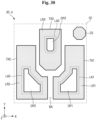
- FIG. 3 is an enlarged plan view of portion Q1 of FIG. 1 , and more specifically, is a schematic plan view of a display substrate included in the display device of FIG. 1 .
- FIG. 4 is an enlarged plan view of portion Q1 of FIG. 1 , and more specifically, is a schematic plan view of a color conversion substrate included in the display device of FIG. 1 .
- a plurality of emission areas and a non-emission area NLA may be defined on the display substrate 10 in the display area DA.
- a first emission area LA1, a second emission area LA2, and a third emission area LA3 may be defined in the display area DA of the display substrate 10.
- light generated from the light emitting element of the display substrate 10 may be emitted to the outside of the display substrate 10, and in the non-emission area NLA, light may not be emitted to the outside of the display substrate 10.
- light provided to the color conversion substrate 30 from the first emission area LA1, the second emission area LA2, and the third emission area LA3 may be light of a third color.
- the light of the third color may be blue light, and may have a peak wavelength in a range of about 440 nm to about 480 nm.
- the first emission area LA1, the second emission area LA2, and the third emission area LA3 may form one group (hereinafter, "emission area group"), and a plurality of groups may be defined in the display area DA.
- the emission area group may be repeatedly disposed along the first direction X and the second direction Y.
- each of the first emission area LA1 and the second emission area LA2 may include a region (hereinafter, "first extended region”) extending along the first direction X and a region (hereinafter, "second extended region”) extending along the second direction Y.
- first extended region of the first emission area LA1 and the first extended region of the second emission area LA2 may be disposed to face each other.
- the third emission area LA3 may be located to one side of the first emission area LA1 and the second emission area LA2 in the second direction Y, and more specifically, to the upper left of the first emission area LA1 and the upper right of the second emission area LA2.
- the present disclosure is not limited thereto, and the arrangement of the first emission area LA1, the second emission area LA2, and the third emission area LA3 may be variously changed.
- the size of at least one of the first emission area LA1, the second emission area LA2, or the third emission area LA3 may be different from the size of another one thereof.
- the size of the third emission area LA3 may be smaller than that of the first emission area LA1 and that of the second emission area LA2.
- the size of the second emission area LA2 may be the same as or smaller than that of the first emission area LA1.
- the present disclosure is not limited thereto, and in another embodiment, the size of the first emission area LA1, the size of the second emission area LA2, and the size of the third emission area LA3 may be substantially the same. In addition, the magnitude relationship between the sizes of the emission areas may be variously modified.
- the non-display area NDA of the display substrate 10 may be located around the display area DA and may surround the display area DA.
- a plurality of light transmitting areas and a light blocking area BA may be defined in the color conversion substrate 30.
- light emitted from the display substrate 10 may pass through the color conversion substrate 30 to be provided to the outside of the display device 1.
- the light blocking area BA may be a region where light emitted from the display substrate 10 does not transmit.
- a first light transmitting area TA1, a second light transmitting area TA2, and a third light transmitting area TA3 may be defined in the color conversion substrate 30.
- the first light transmitting area TA1 may correspond to or overlap the first emission area LA1.
- the second light transmitting area TA2 may correspond to or overlap the second emission area LA2, and the third light transmitting area TA3 may correspond to or overlap the third emission area LA3.
- the size of the first light transmitting area TA1 may be larger than that of the first emission area LA1, and in plan view, the edge of the first light transmitting area TA1 may completely surround the edge of the first emission area LA1.
- the size of the second light transmitting area TA2 may be larger than that of the second emission area LA2, and in plan view, the edge of the second light transmitting area TA2 may completely surround the edge of the second emission area LA2.
- the size of the third light transmitting area TA3 may be larger than that of the third emission area LA3, and in plan view, the edge of the third light transmitting area TA3 may completely surround the edge of the third emission area LA3.
- the size of the first light transmitting area TA1 may be substantially the same as that of the second light transmitting area TA2, and the size of the third light transmitting area TA3 may be smaller than that of the first light transmitting area TA1 and that of the second light transmitting area TA2.
- the light of the third color provided from the display substrate 10 may be provided to the outside of the display device 1 in a state where part thereof has been wavelength-converted and another part thereof has not been wavelength-converted through the first light transmitting area TA1, the second light transmitting area TA2, and the third light transmitting area TA3.
- first exit light When the light emitted from the first light transmitting area TA1 to the outside of the display device 1 is referred to as first exit light, the light emitted from the second light transmitting area TA2 to the outside of the display device 1 is referred to as second exit light and the light emitted from the third light transmitting area TA3 to the outside of the display device 1 is referred to as third exit light
- the first exit light may be light of a first color
- the second exit light may be light of a second color different from the first color
- third exit light may be light of a third color.
- the light of the third color may be blue light having a peak wavelength in a range of 440 nm to about 480 nm as described above, and the light of the first color may be red light having a peak wavelength in a range of about 610 nm to about 650 nm.
- the light of the second color may be green light having a peak wavelength in a range of about 510 nm to about 550 nm.
- the light of the first color and the light of the second color may be light into which the light of the third color has been wavelength-converted.
- the light blocking area BA may be positioned around the first light transmitting area TA1, the second light transmitting area TA2, and the third light transmitting area TA3 of the color conversion substrate 30 in the display area DA. In some embodiments, the light blocking area BA may surround the first light transmitting area TA1, the second light transmitting area TA2, and the third light transmitting area TA3.
- a column spacer CS may be positioned in the light blocking area BA of the color conversion substrate 30 in the display area DA.
- the column spacer CS may maintain a constant gap between the color conversion substrate 30 and the display substrate 10, thereby improving uniformity and spreadability of the filler 70.
- the column spacer CS may be positioned to one side of the first light transmitting area TA1 in the second direction Y and to one side of the third light transmitting area TA3 in the first direction X.
- FIG. 5 is a cross-sectional view of a display device according to one embodiment, taken along line X3-X3' of FIGS. 3 and 4 .
- FIG. 6 is a cross-sectional view of a display device according to one embodiment, taken along line X5-X5' of FIGS. 3 and 4 .
- FIG. 7 is a cross-sectional view of a display device according to one embodiment, taken along line X7-X7' of FIGS. 3 and 4 .
- FIG. 8 is an enlarged view of portion Q3 of FIG. 5 .
- FIG. 9 is a view showing a modified example of the structure shown in FIG. 8 .
- FIG. 10 is an enlarged view of portion Q5 of FIG. 5 .
- FIG. 11 is an enlarged view of portion Q7 of FIG. 5 .
- the display device 1 may include the display substrate 10 and the color conversion substrate 30, and may further include the filler 70 positioned between the display substrate 10 and the color conversion substrate 30.
- the first base portion 110 may be made of a light transmissive material.
- the first base portion 110 may be a glass substrate or a plastic substrate.
- the first base portion 110 may have flexibility.
- the first base portion 110 may further include a separate layer, e.g., a buffer layer or an insulating layer, disposed on the glass substrate or the plastic substrate.
- the plurality of emission areas LA1, LA2, and LA3 and the non-emission area NLA may be defined in the first base portion 110.
- switching elements T1, T2, and T3 may be positioned on the first base portion 110.
- the first switching element T1 may overlap the first emission area LA1
- the second switching element T2 may overlap the second emission area LA2
- the third switching element T3 may overlap the third emission area LA3.
- the first switching element T1, the second switching element T2, and the third switching element T3 do not overlap the non-emission area NLA, this is merely an example.
- at least one of the first switching element T1, the second switching element T2, or the third switching element T3 may overlap the non-emission area NLA.
- all of the first switching element T1, the second switching element T2, and the third switching element T3 may overlap the non-emission area NLA.
- a plurality of signal lines that transmit signals to the switching elements may be further positioned on the first base portion 110.
- Each of the first switching element T1, the second switching element T2, and the third switching element T3 may be a thin film transistor.
- An insulating layer 130 may be located on the first switching element T1, the second switching element T2 and the third switching element T3.
- the insulating layer 130 may be a planarization layer.
- the insulating layer 130 may include an organic material.
- the insulating layer 130 may include acrylic resin, epoxy resin, imide resin, ester resin, or the like.
- the insulating layer 130 may include a photosensitive organic material.
- a first anode electrode AE1, a second anode electrode AE2, and a third anode electrode AE3 may be positioned on the insulating layer 130.
- the first anode electrode AE1 may overlap the first emission area LA1 and may at least partially extend to the non-emission area NLA.
- the second anode electrode AE2 may overlap the second emission area LA2, and at least a portion thereof may extend to the non-emission area NLA.
- the third anode electrode AE3 may overlap the third emission area LA3, and at least a portion thereof may extend to the non-emission area NLA.
- the first anode electrode AE1 may be connected to the first switching element T1 through the insulating layer 130, and the second anode electrode AE2 may be connected to the second switching element T2 through the insulating layer 130.
- the third anode electrode AE3 may be connected to the third switching element T3 through the insulating layer 130.
- the first anode electrode AE1, the second anode electrode AE2, and the third anode electrode AE3 may be reflective electrodes.
- the first anode electrode AE1, the second anode electrode AE2 and the third anode electrode AE3 may be a metal layer containing at least one of Ag, Mg, Al, Pt, Pd, Au, Ni, Nd, Ir, or Cr.
- the first anode electrode AE1, the second anode electrode AE2 and the third anode electrode AE3 may further include a metal oxide layer stacked on the metal layer.
- the first anode electrode AE1, the second anode electrode AE2, and the third anode electrode AE3 may have a multilayer structure, e.g., a two-layer structure of ITO/Ag, Ag/ITO, ITO/Mg, or ITO/MgF,. or a three-layer structure such as ITO/Ag/ITO.
- a pixel defining layer 150 may be positioned on the first anode electrode AE1, the second anode electrode AE2 and the third anode electrode AE3.
- the pixel defining layer 150 may include an opening exposing the first anode electrode AE1, an opening exposing the second anode electrode AE2, and an opening exposing the third anode electrode AE3, and may define the first emission area LA1, the second emission area LA2, the third emission area LA3, and the non-emission area NLA. That is, a region of the first anode electrode AE1 which is exposed without being covered by the pixel defining layer 150 may be the first emission area LA1.
- a region of the second anode electrode AE2 which is exposed without being covered by the pixel defining layer 150 may be the second emission area LA2
- a region of the third anode electrode AE3 which is exposed without being covered by the pixel defining layer 150 may be the third emission area LA3.
- a region where the pixel defining layer 150 is located may be the non-emission area NLA.
- the pixel defining layer 150 may include an organic insulating material selected from the group consisting of acrylic resin, epoxy resin, phenolic resin, polyamide resin, polyimide resin, unsaturated polyester resin, polyphenylene resin, polyphenylenesulfide resin and benzocyclobutene (BCB).
- an organic insulating material selected from the group consisting of acrylic resin, epoxy resin, phenolic resin, polyamide resin, polyimide resin, unsaturated polyester resin, polyphenylene resin, polyphenylenesulfide resin and benzocyclobutene (BCB).
- the pixel defining layer 150 may overlap a first color filter 231, a second color filter 233, and a third color filter 235, which will be described later. In addition, in some embodiments, the pixel defining layer 150 may also overlap a bank pattern 370 to be described later.
- a light emitting layer OL may be positioned on the first anode electrode AE1, the second anode electrode AE2, the third anode electrode AE3, and the pixel defining layer 150.
- the light emitting layer OL may have a shape of a continuous film formed over the plurality of emission areas LA1, LA2, and LA3 and the non-emission area NLA. A more detailed description of the light emitting layer OL will be given later.
- a cathode electrode CE may be positioned on the light emitting layer OL.
- the cathode electrode CE may have a semi-transmissive or transmissive property.
- the cathode electrode CE may include Ag, Mg, Cu, Al, Pt, Pd, Au, Ni, Nd, Ir, Cr, Li, Ca, LiF/Ca, LiF/Al, Mo, Ti or a compound or mixture thereof, such as a mixture of Ag and Mg.
- the cathode electrode CE may have a thickness of tens to hundreds of angstroms.
- the cathode electrode CE may include a transparent conductive oxide (TCO).
- TCO transparent conductive oxide
- the cathode electrode CE may include tungsten oxide (WxOy), titanium oxide (TiO 2 ), indium tin oxide (ITO), indium zinc oxide (IZO), zinc oxide (ZnO), indium tin zinc oxide (ITZO), magnesium oxide (MgO) or the like.
- the first anode electrode AE1, the light emitting layer OL and the cathode electrode CE may constitute a first light emitting element ED1.
- the second anode electrode AE2, the light emitting layer OL and the cathode electrode CE may constitute a second light emitting element ED2.
- the third anode electrode AE3, the light emitting layer OL and the cathode electrode CE may constitute a third light emitting element ED3.
- Each of the first light emitting element ED1, the second light emitting element ED2, and the third light emitting element ED3 may emit emission light LE, and the emission light LE may be provided to the color conversion substrate 30.
- the emission light LE finally emitted from the light emitting layer OL may be mixed light in which a first component LE1 and a second component LE2 are mixed.
- the first component LE1 and the second component LE2 of the emission light LE may each have a peak wavelength of 440 nm or more and less than 480 nm.
- the peak wavelengths of the first component LE1 and the second component LE2 may be selected to be the same as or to be different from each other. That is, the emission light LE may be blue light.
- the light emitting layer OL may have a structure, e.g., a tandem structure, in which a plurality of light emitting layers are disposed to overlap each other.
- the light emitting layer OL may include a first stack ST1 including a first light emitting layer EML1, a second stack ST2 positioned on the first stack ST1 and including a second light emitting layer EML2, a third stack ST3 positioned on the second stack ST2 and including a third light emitting layer EMI,3, a first charge generation layer CGL1 positioned between the first stack ST1 and the second stack ST2, and a second charge generation layer CGL2 positioned between the second stack ST2 and the third stack ST3.
- the first stack ST1, the second stack ST2, and the third stack ST3 may be disposed to overlap each other.
- the first light emitting layer EMI,1, the second light emitting layer EML2, and the third light emitting layer EML3 may be disposed to overlap each other.
- all of the first light emitting layer EML1, the second light emitting layer EML2, and the third light emitting layer EML3 may emit light of the blue wavelength.
- each of the first light emitting layer EMI,1, the second light emitting layer EML2, and the third light emitting layer EML3 may be a blue light emitting layer and may include an organic material.
- the present disclosure is not limited thereto, and in another embodiment, at least one of the first light emitting layer EMI,1, the second light emitting layer EML2, or the third light emitting layer EML3 may include an inorganic material that emits blue light.
- At least one of the first light emitting layer EML1, the second light emitting layer EML2, or the third light emitting layer EML3 may be formed of an inorganic light emitting element or may be a part of an inorganic light emitting element.
- the inorganic light emitting element may have a width of a nano size.
- At least one of the first light emitting layer EML1, the second light emitting layer EML2, or the third light emitting layer EML3 may emit first blue light having a first peak wavelength, and at least another one thereof may emit second blue light having a second peak wavelength different from the first peak wavelength.
- any one of the first light emitting layer EML1, the second light emitting layer EML2, and the third light emitting layer EML3 may emit the first blue light having the first peak wavelength, and the other two thereof may emit the second blue light having the second peak wavelength.
- the emission light LE finally emitted from the light emitting layer OL may be mixed light in which the first component LE1 and the second component LE2 are mixed, the first component LE1 may be the first blue light having the first peak wavelength, and the second component LE2 may be the second blue light having the second peak wavelength.
- one of the first peak wavelength and the second peak wavelength may be in a range of 440 nm or more and less than 460 nm, and the other one thereof may be in a range of 460 nm or more and 480 nm or less.
- the range of the first peak wavelength and the range of the second peak wavelength are not limited thereto.
- the range of the first peak wavelength and the range of the second peak wavelength may both include 460 nm.
- one of the first blue light and the second blue light may be deep blue color, and the other one thereof may be sky blue color.
- the emission light LE emitted from the light emitting layer OL may be blue light and may include a long wavelength component and a short wavelength component. Therefore, ultimately, the light emitting layer OL may emit blue light having an emission peak in a broader wavelength range, as the emission light LE. Accordingly, there is an advantage in that color visibility can be improved at a side viewing angle compared to a conventional light emitting element that emits blue light having a sharp emission peak.
- each of the first light emitting layer EML1, the second light emitting layer EML2, and the third light emitting layer EML3 may include a host and a dopant.
- a material of the host is not particularly limited as long as it is generally used.
- the first light emitting layer EMI,1, the second light emitting layer EML2, and the third light emitting layer EML3 that emit blue light may each include a fluorescent material containing any one selected from the group consisting of, e.g., spiro-DPVBi, spiro-6P, distyryl-benzene (DSB), distyryl-arylene (DSA), polyfluorene (PFO)-based polymer, and poly(p-phenylene vinylene) (PPV)-based polymer.
- a phosphorescent material containing an organometallic complex such as (4,6-F2ppy)2Irpic may be included.
- the material that emits blue light is not limited thereto.
- the first light emitting layer EMI,1, the second light emitting layer EML2, or the third light emitting layer EML3 emits blue light in a wavelength band different from that of at least another one thereof.
- the first light emitting layer EML1, the second light emitting layer EML2, and the third light emitting layer EML3 may include the same material, and a method of adjusting a resonance distance may be used.
- At least one of the first light emitting layer EML1, the second light emitting layer EML2, and the third light emitting layer EML3, and at least another one of the first light emitting layer EML1, the second light emitting layer EML2, and the third light emitting layer EML3 may include different materials from each other.
- All of the first light emitting layer EMI,1, the second light emitting layer EML2, and the third light emitting layer EML3 may emit blue light having a peak wavelength of 440 nm to 480 nm, and may be made of the same material.
- At least one of the first light emitting layer EML1, the second light emitting layer EML2, or the third light emitting layer EML3 may emit first blue light having a first peak wavelength, another one thereof may emit second blue light having a second peak wavelength different from the first peak wavelength, and the remaining one thereof may emit third blue light having a third peak wavelength different from the first peak wavelength and the second peak wavelength.
- any one of the first peak wavelength, the second peak wavelength, and the third peak wavelength may be in a range of 440 nm or more and less than 460 nm.
- Another one of the first peak wavelength, the second peak wavelength, and the third peak wavelength may be in a range of 460 nm or more and less than 470 nm, and the remaining one thereof may be in a range of 470 nm or more and 480 nm or less.
- the emission light LE emitted from the light emitting layer OL is blue light and includes a long wavelength component, an intermediate wavelength component, and a short wavelength component. Therefore, ultimately, the light emitting layer OL may emit blue light having an emission peak in a broader wavelength range as the emission light LE, thereby improving the color visibility at a side viewing angle.
- At least one of the first light emitting layer EML1, the second light emitting layer EML2, or the third light emitting layer EML3 may emit light of the third color, e.g., blue light, and at least another one thereof may emit light of the second color, e.g., green light.
- the peak wavelength of the blue light emitted from at least one of the first light emitting layer EML1, the second light emitting layer EML2, or the third light emitting layer EML3 may be in a range of 440 nm or more and 480 nm or less, or in a range of 460 nm or more and 480 nm or less.
- the green light emitted from at least another one of the first light emitting layer EMI,1, the second light emitting layer EML2, or the third light emitting layer EML3 may have a peak wavelength in a range of 510 nm to 550 nm.
- any one of the first light emitting layer EML1, the second light emitting layer EML2, and the third light emitting layer EML3 may be a green light emitting layer that emits green light, and the other two thereof may be blue light emitting layers that emit blue light.
- the blue light emitted from the two blue light emitting layers may have the same peak wavelength range, or may have different peak wavelength ranges.
- the emission light LE emitted from the light emitting layer OL may be mixed light in which the first component LE1 that is blue light and the second component LE2 that is green light are mixed.
- the emission light LE may have a sky blue color.
- the emission light LE emitted from the light emitting layer OL is mixed light of blue light and green light, and includes a long wavelength component and a short wavelength component. Therefore, ultimately, the light emitting layer OL may emit blue light having an emission peak in a broader wavelength range as the emission light LE, thereby improving the color visibility at a side viewing angle.
- the second component LE2 of the emission light LE is green light
- the green light component of the light provided from the display device 1 to the outside may be supplemented, thereby improving the color reproducibility of the display device 1.
- a green light emitting layer among the first light emitting layer EML1, the second light emitting layer EML2, and the third light emitting layer EML3 may include a host and a dopant.
- a material of the host including the green light emitting layer is not particularly limited as long as it is generally used.
- the dopant included in the green light emitting layer may include a fluorescent material containing, for example, tris(8-hydroxyquinolinato)aluminium(III) (Alq3), or a phosphorescent material such as fac tris(2-phenylpyridine)iridium (Ir(ppy)3), bis(2-phenylpyridine)(acetylacetonate)iridium(III) (Ir(ppy)2(acac)), and 2-phenyl-4-methyl-pyridine iridium (Ir(mpyp)3).
- a fluorescent material containing, for example, tris(8-hydroxyquinolinato)aluminium(III) (Alq3), or a phosphorescent material such as fac tris(2-phenylpyridine)iridium (Ir(ppy)3), bis(2-phenylpyridine)(acetylacetonate)iridium(III) (Ir(ppy)2(acac)), and 2-phenyl-4-methyl-
- the first charge generation layer CGL1 may be positioned between the first stack ST1 and the second stack ST2.
- the first charge generation layer CGL1 may serve to allow electric charge to be injected into each light emitting layer.
- the first charge generation layer CGL1 may serve to control charge balance between the first stack ST1 and the second stack ST2.
- the first charge generation layer CGL1 may include an n-type charge generation layer CGL11 and a p-type charge generation layer CGL12.
- the p-type charge generation layer CGL12 may be disposed on the n-type charge generation layer CGL11, and between the n-type charge generation layer CGL11 and the second stack ST2.
- the first charge generation layer CGL1 may have a structure in which the n-type charge generation layer CGL11 and the p-type charge generation layer CGL12 are in contact with each other.
- the n-type charge generation layer CGL11 is disposed closer to the anode electrodes AE1, AE2 ( FIG. 7 ) and AE3 ( FIG. 7 ) than the cathode electrode CE.
- the p-type charge generation layer CGL12 is disposed closer to the cathode electrode CE than the anode electrodes AE1, AE2 ( FIG. 7 ) and AE3 ( FIG. 7 ).
- the n-type charge generation layer CGL11 supplies electrons to the first light emitting layer EML1 adjacent to the anode electrodes AE1, AE2 ( FIG.
- the first charge generation layer CGL1 is disposed between the first stack ST1 and the second stack ST2 to provide electric charge to each light emitting layer, thereby increasing light emission efficiency, and decreasing a driving voltage.
- the first stack ST1 may be positioned on the first anode electrode AE1( FIG. 8 ), the second anode electrode AE2( FIG. 7 ), and the third anode electrode AE3( Fig 7 ) and may further include a first hole transport layer HTL1, a first electron block layer BII,1, and a first electron transport layer ETL1.
- the first hole transport layer HTL1 may be positioned on the first anode electrode AE1, the second anode electrode AE2( FIG. 7 ), and the third anode electrode AE3 ( FIG. 7 ).
- the first hole transport layer HTL1 serves to facilitate the transport of holes and may include a hole transport material.
- the hole transport material may include a carbazole-based derivative such as N-phenylcarbazole or polyvinylcarbazole, a fluorene-based derivative, a triphenylamine-based derivative such as N,N'-bis(3-methylphenyl)-N,N'-diphenyl-[1,1-biphenyl]-4,4'-diamine (TPD) or 4,4',4"-tris(N-carbazolyl)triphenylamine (TCTA), N,N'-di(1-naphthyl)-N,N'-diphenylbenzidine (NPB), 4,4'-Cyclohexylidenebis[N,N-bis(4-methylphenyl)benzenamine] (TAPC), or the like, but is not limited thereto.
- a carbazole-based derivative such as N-phenylcarbazole or polyvinylcarbazole
- fluorene-based derivative such as N
- the first electron block layer BIL1 may be positioned on the first hole transport layer HTL1, and between the first hole transport layer HTL1 and the first light emitting layer EML1.
- the first electron block layer BIL1 may include a hole transport material and a metal or metal compound to prevent electrons generated in the first light emitting layer EML1 from moving into the first hole transport layer HTL1.
- the first hole transport layer HTL1 and the first electron block layer BIL1 described above may also be formed of a single layer in which respective materials are mixed.
- the first electron transport layer ETL1 may be positioned on the first light emitting layer EMI,1, and between the first charge generation layer CGL1 and the first light emitting layer EML1.
- the first electron transport layer ETL1 may include an electron transport material such as Tris(8-hydroxyquinolinato)aluminum (Alq3), 1,3,5-Tri(1-phenyl-1H-benzo[d]imidazol-2-yl)phenyl (TPBi), 2,9-Dimethyl-4,7-diphenyl-1,10-phenanthroline (BCP), 4,7-Diphenyl-1,10-phenanthroline (Bphen), 3-(4-Biphenylyl)-4-phenyl-5-tert-butylphenyl-1,2,4-triazole (TAZ), 4-(Naphthalen-1-yl)-3,5-diphenyl-4H-1,2,4-triazole (NTAZ), 2-(4-Biphenylyl)-5-(4-tert)
- the second stack ST2 may be positioned on the first charge generation layer CGL1, and further include a second hole transport layer HTL2, a second electron block layer BIL2, and a second electron transport layer ETL1.
- the second hole transport layer HTL2 may be positioned on the first charge generation layer CGL1.
- the second hole transport layer HTL2 may be made of the same material as the first hole transport layer HTL1, or may include one or more materials selected from examples of materials included in the first hole transport layer HTL1.
- the second hole transport layer HTL2 may be formed of a single layer or a plurality of layers.
- the second electron block layer BIL2 may be positioned on the second hole transport layer HTL2, and between the second hole transport layer HTL2 and the second light emitting layer EML2.
- the second electron block layer BIL2 may be formed of the same material and the same structure as the first electron block layer BIL1, or may include one or more materials selected from examples of materials included in the first electron block layer BIL1.
- the second electron transport layer ETL2 may be positioned on the second light emitting layer EML2, and between the second charge generation layer CGL2 and the second light emitting layer EML2.
- the second electron transport layer ETL2 may be formed of the same material and the same structure as the first electron transport layer ETL1, or may include one or more materials selected from examples of materials included in the first electron transport layer ETL1.
- the second electron transport layer ETL2 may be formed of a single layer or a plurality of layers.
- the second charge generation layer CGL2 may be positioned on the second stack ST2 and between the second stack ST2 and the third stack ST3.
- the second charge generation layer CGL2 may have the same structure as the first charge generation layer CGL1 described above.
- the second charge generation layer CGL2 may include an n-type charge generation layer CGL21 disposed closer to the second stack ST2 and a p-type charge generation layer CGL22 disposed closer to the cathode electrode CE.
- the p-type charge generation layer CGL22 may be disposed on the n-type charge generation layer CGL21.
- the second charge generation layer CGL2 may have a structure in which the n-type charge generation layer CGL21 and the p-type charge generation layer CGL22 are in contact with each other.
- the first charge generation layer CGL1 and the second charge generation layer CGL2 may be made of different materials, or may be made of the same material.
- the third stack ST3 may be positioned on the second charge generation layer CGL2, and may further include a third hole transport layer HTL3 and a third electron transport layer ETL3.
- the third hole transport layer HTL3 may be positioned on the second charge generation layer CGL2.
- the third hole transport layer HTL3 may be made of the same material as the first hole transport layer HTL1, or may include one or more materials selected from examples of materials included in the first hole transport layer HTL1.
- the third hole transport layer HTL3 may be formed of a single layer or a plurality of layers. When the third hole transport layer HTL3 is formed of a plurality of layers, each layer may include a different material.
- the third electron transport layer ETL3 may be positioned on the third light emitting layer EML3, and between the cathode electrode CE and the third light emitting layer EML3.
- the third electron transport layer ETL3 may be formed of the same material and the same structure as the first electron transport layer ETL1, or may include one or more materials selected from examples of materials included in the first electron transport layer ETL1.
- the third electron transport layer ETL3 may be formed of a single layer or a plurality of layers. When the third electron transport layer ETL3 is formed of a plurality of layers, each layer may include a different material.
- a hole injection layer may be further positioned at least one of between the first stack ST1 and the first anode electrode AE1between the second anode electrode AE2( FIG. 7 ) and the third anode electrode AE3( FIG. 7 ) between the second stack ST2 and the first charge generation layer CGL1, or between the third stack ST3 and the second charge generation layer CGL2.
- the hole injection layer may serve to allow holes to be more smoothly injected into the first light emitting layer EML1, the second light emitting layer EML2, and the third light emitting layer EML3.
- the hole injection layer may be formed of one or more selected from the group consisting of cupper phthalocyanine (CuPc), poly(3,4)-ethylenedioxythiophene (PEDOT), polyaniline (PANI), and N,N-dinaphthyl-N,N'-diphenyl benzidine (NPD), but is not limited thereto.
- the hole injection layer may be positioned between the first stack ST1 and the first anode electrode AE1, between the second anode electrode AE2( FIG. 7 ) and the third anode electrode AE3( FIG. 7 ), between the second stack ST2 and the first charge generation layer CGL1, and between the third stack ST3 and the second charge generation layer CGL2.
- an electron injection layer may be further positioned at least one of between the third electron transport layer ETL3 and the cathode electrode CE, between the second charge generation layer CGL2 and the second stack ST2, or between the first charge generation layer CGL1 and the first stack ST1.
- the electron injection layer may serve to facilitate electron injection, and may use tris(8-hydroxyquinolino)aluminum (Alq3), PBD, TAZ, spiro-PBD, BAlq, or SAlq, but is not limited thereto.
- the electron injection layer may be a metal halide compound, for example, may be any one or more selected from the group consisting of MgF 2 , LiF, NaF, KF, RbF, CsF, FrF, LiI, NaI, KI, RbI, CsI, FrI, and CaF 2 , but is not limited thereto.
- the electron injection layer may include a lanthanum-based material such as Yb, Sm, or Eu.
- the electron injection layer may include both a metal halide material and a lanthanum-based material, such as RbLYb or KI:Yb.
- the electron injection layer may be formed by co-depositing the metal halide material and the lanthanum-based material.
- the electron injection layer may be positioned between the third electron transport layer ETL3 and the cathode electrode CE, between the second charge generation layer CGL2 and the second stack ST2, and between the first charge generation layer CGL1 and the first stack ST1.
- the structure of the light emitting layer OL may be modified.
- the light emitting layer OL may be modified into a light emitting layer OLa shown in FIG. 9 .
- the light emitting layer OLa shown in FIG. 9 may further include a fourth stack ST4 positioned between the third stack ST3 and the second stack ST2, and a third charge generation layer CGL3 positioned between the third stack ST3 and the fourth stack ST2.
- the fourth stack ST4 may include a fourth light emitting layer EML4, and may further include a fourth hole transport layer HTL4, a third electron block layer BIL4, and a fourth electron transport layer ETL4.
- At least one of the first light emitting layer EML1, the second light emitting layer EML2, the third light emitting layer EML3, and the fourth light emitting layer EML4 may emit green light and at least one of the first light emitting layer EML1, the second light emitting layer EML2, the third light emitting layer EML3, or the fourth light emitting layer EML4, and at least another one thereof may emit blue light having different peak wavelength ranges.
- At least one of the first light emitting layer EML1, the second light emitting layer EML2, the third light emitting layer EML3, or the fourth light emitting layer EML4 may emit green light, and at least another one thereof may emit blue light.
- any one of the first light emitting layer EML1, the second light emitting layer EMI,2, the third light emitting layer EMI,3, and the fourth light emitting layer EML4 may be a green light emitting layer, and the other three thereof may all be blue light emitting layers.
- the fourth hole transport layer HTL4 may be positioned on the second charge generation layer CGL2.
- the fourth hole transport layer HTL4 may be made of the same material as the first hole transport layer HTL1, or may include one or more materials selected from examples of materials included in the first hole transport layer HTL1.
- the fourth hole transport layer HTL4 may be formed of a single layer or a plurality of layers. When the fourth hole transport layer HTL4 is formed of a plurality of layers, each layer may include a different material.
- the third electron block layer BIL4 may be positioned on the fourth hole transport layer HTL4, and may be positioned between the fourth hole transport layer HTL4 and the fourth light emitting layer EML4.
- the third electron block layer BIL4 may be formed of the same material and the same structure as the first electron block layer BIL1, or may include one or more materials selected from examples of materials included in the first electron block layer BII,1. In some other embodiments, the third electron block layer BIL4 may be omitted.
- the fourth electron transport layer ETL4 may be positioned on the fourth light emitting layer EML4, and may be positioned between the third charge generation layer CGL3 and the fourth light emitting layer EML4.
- the fourth electron transport layer ETL4 may be formed of the same material and the same structure as the first electron transport layer ETL1, or may include one or more materials selected from examples of materials included in the first electron transport layer ETL1.
- the fourth electron transport layer ETL4 may be formed of a single layer or a plurality of layers. When the fourth electron transport layer ETL4 is formed of a plurality of layers, each layer may include a different material.
- the third charge generation layer CGL3 may have the same structure as the first charge generation layer CGL1 described above.
- the third charge generation layer CGL3 may include an n-type charge generation layer CGL31 disposed closer to the fourth stack ST4 and a p-type charge generation layer CGL32 disposed closer to the cathode electrode CE.
- the p-type charge generation layer CGL32 may be disposed on the n-type charge generation layer CGL31.
- the electron injection layer may be further positioned between the fourth stack ST4 and the third charge generation layer CGL3.
- the hole injection layer may be further positioned between the fourth stack ST4 and the second charge generation layer CGL2.
- the light emitting layer OL shown in FIG. 8 and the light emitting layer OLa shown in FIG. 9 may not include a red light emitting layer in common, and thus may not emit light of the first color, e.g., red light. That is, the emission light LE may not include a light component having a peak wavelength of 610 nm to about 650 nm.
- a first capping layer 160 may be positioned on the cathode electrode CE.
- the first capping layer 160 may be disposed in common in the first emission area LA1, the second emission area LA2, the third emission area LA3, and the non-emission area NLA, and may improve viewing angle characteristics and increase external luminous efficiency.
- the first capping layer 160 may include at least one of an inorganic material or an organic material having light transmittance. That is, the first capping layer 160 may be formed of an inorganic layer, an organic layer, or an organic layer including inorganic particles.
- the first capping layer 160 may include a triamine derivative, a carbazole biphenyl derivative, an arylenediamine derivative, tris(8-hydroxyquinolino)aluminum (Alq3), or the like.
- the first capping layer 160 may be formed of a mixture of a high refractive material and a low refractive material.
- the first capping layer 160 may include two layers having different refractive indices, e.g., a high refractive layer and a low refractive layer.
- the thin film encapsulation layer 170 may be disposed on the first capping layer 160.
- the thin film encapsulation layer 170 is disposed in common to the first emission area LA1, the second emission area LA2, the third emission area LA3 and the non-emission area NLA.
- the thin film encapsulation layer 170 may directly cover the first capping layer 160.
- the thin film encapsulation layer 170 may include a lower inorganic layer 171, an organic layer 173, and an upper inorganic layer 175 sequentially stacked on the first capping layer 160.
- the lower inorganic layer 171 may cover the first light emitting element ED1, the second light emitting element ED2, and the third light emitting element ED3 in the display area DA.
- the lower inorganic layer 171 may include an inorganic material and may have a multilayer structure.
- the organic layer 173 may be positioned on the lower inorganic layer 171.
- the organic layer 173 may cover the first light emitting element ED1, the second light emitting element ED2, and the third light emitting element ED3 in the display area DA.
- the organic layer 173 may be formed of acrylic resin, methacrylic resin, polyisoprene, vinyl resin, epoxy resin, urethane resin, cellulose resin, perylene resin or the like.
- the upper inorganic layer 175 may be positioned on the organic layer 173.
- the upper inorganic layer 175 may cover the organic layer 173.
- the upper inorganic layer 175 may be in direct contact with the lower inorganic layer 171 in the non-display area to form an inorganic-inorganic junction.
- each of the lower inorganic layer 171 and the upper inorganic layer 175 may be made of silicon nitride, aluminum nitride, zirconium nitride, titanium nitride, hafnium nitride, tantalum nitride, silicon oxide, aluminum oxide, titanium oxide, tin oxide, cerium oxide, silicon oxynitride (SiON), lithium fluoride, or the like.
- each of the lower inorganic layer 171 and the upper inorganic layer 175 may be formed into a single layer, but is not limited thereto. At least one of the lower inorganic layer 171 or the upper inorganic layer 175 may have a structure, e.g., a multilayer structure, in which a plurality of layers each made of an inorganic material are stacked.
- the structure of the thin film encapsulation layer 170 may be variously modified.
- FIG. 12 is a plan view illustrating a schematic arrangement of a third color filter in a color conversion substrate of a display device according to one embodiment.
- FIG. 13 is a plan view illustrating a schematic arrangement of a first color filter in a color conversion substrate of a display device according to one embodiment.
- FIG. 14 is a plan view illustrating a schematic arrangement of a second color filter in a color conversion substrate of a display device according to one embodiment.
- FIG. 15 is a plan view illustrating a schematic arrangement of a bank pattern in a color conversion substrate of a display device according to one embodiment.
- FIG. 16 is a plan view illustrating a schematic arrangement of an optical pattern and a column spacer in a color conversion substrate of a display device according to one embodiment.
- FIG. 17 is a plan view illustrating a schematic arrangement of a first wavelength conversion pattern, a second wavelength conversion pattern, and a light transmission pattern in a color conversion substrate of a display device according to one embodiment.
- a second base portion 310 shown in FIGS. 5 to 7 may be made of a light transmissive material.
- the second base portion 310 may include a glass substrate or a plastic substrate. In some embodiments, the second base portion 310 may further include a separate layer, for example, an insulating layer such as an inorganic layer, located on the glass substrate or the plastic substrate.
- the plurality of light transmitting areas TA1, TA2, and TA3 and the light blocking area BA may be defined in the second base portion 310.
- the third color filter 235 may be positioned on one surface of the second base portion 310 facing the display substrate 10.
- the third color filter 235 may be disposed to overlap the third light transmitting area TA3.
- the third color filter 235 may selectively transmit light of the third color (e.g., blue light), and may block or absorb light of the first color (e.g., red light) and light of the second color (e.g., green light).
- the third color filter 235 may be a blue color filter, and may include a blue colorant such as a blue dye or a blue pigment.
- the colorant is a concept including both a dye and a pigment.
- the third color filter 235 may be disposed to further overlap the non-emission area NLA or the light blocking area BA.
- a portion of the third color filter 235 that overlaps the light blocking area BA may absorb part of light flowing into the display device 1 from the outside of the display device 1, thereby reducing reflected light caused by external light. A significant portion of the external light is reflected, causing a problem of distorting the color reproducibility of the display device 1.
- the third color filter 235 when the third color filter 235 is further positioned in the non-emission area NLA and the non-display area NDA, color distortion caused by reflection of external light may be reduced.
- the third color filter 235 includes a blue colorant
- external light that has passed through the third color filter 235 or reflected light may be blue light.
- the eye color sensibility perceived by a user's eyes depends on the color of the light. More specifically, light in the blue wavelength band may be perceived as less sensitive to the user than light in a green wavelength band and light in a red wavelength band. Accordingly, as the third color filter 235 including the blue colorant is further disposed to overlap the light blocking area BA, the user may perceive the reflected light relatively less sensitively.
- the first color filter 231 and the second color filter 233 may be positioned on one surface of the second base portion 310 facing the display substrate 10.
- the first color filter 231 may be disposed to overlap the first emission area LA1 or the first light transmitting area TA1.
- the first color filter 231 may block or absorb light of the third color (e.g., blue light). That is, the first color filter 231 may function as a blue light blocking filter that blocks blue light. In some embodiments, the first color filter 231 may selectively transmit light of the first color (e.g., red light) and may block or absorb light of the third color (e.g., blue light) and light of the second color (e.g., green light). For example, the first color filter 231 may be a red color filter and may include a red colorant.
- the first color filter 231 may be disposed to further overlap the non-emission area NLA or the light blocking area BA, and in the light blocking area BA, the first color filter 231 may be positioned on the third color filter 235.
- the second color filter 233 may block or absorb light of the third color (e.g., blue light). That is, the second color filter 233 may also function as a blue light blocking filter. In some embodiments, the second color filter 233 may selectively transmit light of the second color (e.g., green light) and may block or absorb light of the third color (e.g., blue light) and light of the first color (e.g., red light). For example, the second color filter 233 may be a green color filter and may include a green colorant.
- the second color filter 233 may be disposed to further overlap the non-emission area NLA or the light blocking area BA, and in the light blocking area BA, the second color filter 233 may be positioned on the first color filter 231.
- the bank pattern 370 may be positioned on one surface of the color filter, e.g., the second color filter 233, facing the display substrate 10 in the light blocking area BA. In some embodiments, the bank pattern 370 may be positioned directly on one surface of the second color filter 233 and may be in direct contact with the second color filter 233.
- the bank pattern 370 may be disposed to overlap the non-emission area NLA. In some embodiments, as shown in FIG. 15 , the bank pattern 370 may surround the first light transmitting area TA1, the second light transmitting area TA2, and the third light transmitting area TA3 in plan view. The bank pattern 370 may partition a space in which a first wavelength conversion pattern 340, a second wavelength conversion pattern 350, and a light transmission pattern 330 are disposed.
- the bank pattern 370 may be formed in one pattern that is integrally connected, but is not limited thereto. In another embodiment, a portion of the bank pattern 370 surrounding the first light transmitting area TA1, a portion of the bank pattern 370 surrounding the second light transmitting area TA2, and a portion of the bank pattern 370 surrounding the third light transmitting area TA3 may be formed in individual patterns separated from each other.
- the bank pattern 370 may serve as a guide for stably positioning the discharged ink composition at a desired position. That is, the bank pattern 370 may function as a barrier wall.
- the bank pattern 370 may overlap the pixel defining layer 150.
- the bank pattern 370 may include an organic material having photocurability. In addition, in some embodiments, the bank pattern 370 may include an organic material having photocurability and including a light blocking material. When the bank pattern 370 has a light blocking property, it is possible to prevent intrusion of light between the emission areas adjacent to each other in the display area DA. For example, the bank pattern 370 may prevent the emission light LE emitted from the second light emitting element ED2 from being incident on the first wavelength conversion pattern 340 that overlaps the first emission area LA1. In addition, the bank pattern 370 may block or prevent external light from penetrating into components positioned therebelow in the non-emission area NLA.
- a first optical pattern LR1 may be positioned on the first color filter 231, a second optical pattern LR2 may be positioned on the second color filter 233, and a third optical pattern LR3 may be positioned on the third color filter 235.
- the first optical pattern LR1 may overlap the first light transmitting area TA1
- the second optical pattern LR2 may overlap the second light transmitting area TA2
- the third optical pattern LR3 may overlap the third light transmitting area TA3.
- the first optical pattern LR1, the second optical pattern LR2, and the third optical pattern LR3 may be located in a space partitioned by the bank pattern 370. In some embodiments, the first optical pattern LR1, the second optical pattern LR2, and the third optical pattern LR3 may be in direct contact with the bank pattern 370.
- the height of each optical pattern may be smaller than the height of the bank pattern 370.
- a height THB of the bank pattern 370 measured from one surface 310s of the second base portion 310 may be greater than a height THL of the first optical pattern LR1 measured from the one surface310s of the second base portion 310.
- the height of each optical pattern may vary depending on a region. For example, as shown in FIG. 11 , the height THL of the first optical pattern LR1 may increases as the distance from the bank pattern 370 decreases.
- one surface of each optical pattern may include a curved surface.
- one surface LR1s of the first optical pattern LR1 facing the first wavelength conversion pattern 340 may have a lens shape.
- the one surface LR1s of the first optical pattern LR1 may have a concave shape curved toward the second base portion 310.
- the first optical pattern LR1, the second optical pattern LR2, and the third optical pattern LR3 may be made of the same material and may be simultaneously formed in the same process. In some embodiments, the first optical pattern LR1, the second optical pattern LR2, and the third optical pattern LR3 may be formed of a material having a low refractive index.
- the refractive index of the first optical pattern LR1 may be lower than that of the first wavelength conversion pattern 340 to be described later.
- the refractive index of the first optical pattern LR1 may be lower than that of the first wavelength conversion pattern 340 by 0.2 or more or 0.3 or more.
- the refractive index of the second optical pattern LR2 may be lower than that of the second wavelength conversion pattern 350 to be described later.
- the refractive index of the second optical pattern LR2 may be lower than that of the second wavelength conversion pattern 350 by 0.2 or more or 0.3 or more.
- the refractive index of the third optical pattern LR3 may be lower than that of the light transmission pattern 330 to be described later.
- the refractive index of the third optical pattern LR3 may be lower than that of the light transmission pattern 330 by 0.2 or more or 0.3 or more.
- the refractive indices of the first optical pattern LR1, the second optical pattern LR2, and the third optical pattern LR3 may be about 1.1 or more and 1.4 or less, about 1.15 or more and about 1.3 or less, or about 1.2 or more and about 1.3 or less.
- each optical pattern may recycle part of light provided from the display substrate 10.
- the first optical pattern LR1 may reflect part of light, emitted toward the second base portion 310 without being light-converted in the first wavelength conversion pattern 340, back to the first wavelength conversion pattern 340. Since the refractive index of the first optical pattern LR1 is smaller than that of the first wavelength conversion pattern 340, a critical angle at which total reflection occurs may be reduced, and accordingly, the amount of light having an incident angle greater than the critical angle may increase. Light having an incident angle greater than the critical angle is totally reflected, and as a result, the amount of light reflected from the one surface LR1s (see FIG. 11 ) of the first optical pattern LR1 may be increased.
- the amount of light recycled to the first wavelength conversion pattern 340 may be increased.
- the first optical pattern LR1 may cover a part of the side surface of the bank pattern 370, it may reflect part of light, emitted toward the bank patern 370 without being light-converted in the first wavelength conversion pattern 340, back to the first wavelength conversion pattern 340. Accordingly, the amount of light recycled may be further increased, and as a result, the light use efficiency of the display device 1 may be further improved.
- the second optical pattern LR2 may improve the light use efficiency in the second light transmitting area TA2
- the third optical pattern LR3 may improve the light use efficiency in the third light transmitting area TA3.
- the refractive index of the first optical pattern LR1 may be smaller than that of the first wavelength conversion pattern 340 and also smaller than that of the first color filter 231.
- the refractive index of the second optical pattern LR2 may be smaller than that of the second wavelength conversion pattern 350 and also smaller than that of the second color filter 233.
- the refractive index of the third optical pattern LR3 may be smaller than that of the light transmission pattern 330 and also smaller than that of the third color filter 235.
- each color filter As the refractive index of each color filter is greater than that of each optical pattern, the light passing through each optical pattern and incident on each color filter may have relatively improved straightness, thereby increasing the light output efficiency of the display device 1.
- each optical pattern may include inorganic particles.
- the second optical pattern LR2 may include a plurality of particles P and a resin R in which the plurality of particles P are dispersed.
- the resin R may include a polymer material.
- the resin R may include any one polymer material or a combination of a plurality of polymer materials selected from the group consisting of an acrylic polymer material, a silicone polymer material, a urethane polymer material, and an imide polymer material.
- the resin R may include at least one of a siloxane polymer, a silsesquioxane polymer, an acrylic polymer substituted with a fluorine atom, a silicone polymer substituted with a fluorine atom, a urethane polymer substituted with a fluorine atom, or an imide polymer substituted with a fluorine atom.
- the resin R may be formed from an acrylic resin, a silicone resin, a urethane resin, or an imide resin.
- the resin R may be formed by solidifying a polymer resin such as an acrylic resin, a silicone resin, a urethane resin, or an imide resin in a high temperature process or an ultraviolet treatment process.
- the resin R may have photosensitivity.
- the particle P may be made of an inorganic material.
- the particle P may be at least one of a zinc oxide (ZnO) particle, a titanium dioxide (TiO 2 ) particle, a magnesium fluoride (MgF 2 ) particle, an iron oxide (Fe 3 O 4 ) particle, a hollow silica particle, a non-hollow silica particle, a nano silicate particle, or a porogen particle.
- ZnO zinc oxide
- TiO 2 titanium dioxide
- MgF 2 magnesium fluoride
- Fe 3 O 4 iron oxide
- the particle when the particle is a hollow particle having a structure with an empty inside, the particle may have a diameter of 20 nm to 200 nm, and a shell thickness of 5 nm to 20 nm.
- the diameter of the hollow may be determined based on the thickness of the shell and the diameter of the particle.
- the refractive indices of the first optical pattern LR1, the second optical pattern LR2, and the third optical pattern LR3 may be adjusted by adjusting the thickness of the shell and the diameter of the particle.
- two or more types of particles P having different diameters may be dispersed in the resin R.
- sicne the first optical pattern LR1 and the third optical pattern LR3 are made of the same material as the second optical pattern LR2, they may also include the resin R and the particles P.
- the column spacer CS may be positioned on the bank pattern 370. As described above, the column spacer CS may maintain a constant gap between the display substrate 10 and the color conversion substrate 30.
- the column spacer CS may be positioned directly on the bank pattern 370 and may be in direct contact with the bank pattern 370.
- the column spacer CS may be made of the same material as that of the first optical pattern LR1, the second optical pattern LR2, and the third optical pattern LR3, and may be simultaneously formed through the same process (e.g., a photoresist process and the like) as that of the first optical pattern LR1, the second optical pattern LR2, and the third optical pattern LR3.
- the refractive index of the column spacer CS may be the same as that of the first optical pattern LR1, and may be lower than that of the first wavelength conversion pattern 340, the second wavelength conversion pattern 350, and the light transmission pattern 330. In some embodiments, the refractive index of the column spacer CS may be about 1.1 or more and 1.4 or less, about 1.15 or more and about 1.3 or less, or about 1.2 or more and about 1.3 or less. In addition, when the optical pattern includes the resin R and the particles P as shown in FIG. 11 , the column spacer CS may also include the resin R and the particles P.
- the first wavelength conversion pattern 340, the second wavelength conversion pattern 350, and the light transmission pattern 330 may be positioned in a space partitioned by the bank pattern 370. In some embodiments, the first wavelength conversion pattern 340, the second wavelength conversion pattern 350, and the light transmission pattern 330 may be positioned in the display area DA.
- the light transmission pattern 330 may overlap the third emission area LA3 or the third light emitting element ED3.
- the light transmission pattern 330 may be located in a space partitioned by the bank pattern 370 in the third light transmitting area TA3, and may be positioned on the third optical pattern LR3.
- the light transmission pattern 330 may be formed in an island shape pattern.
- the light transmission pattern 330 may transmit incident light.
- the emission light LE provided from the third light emitting element ED3 may be blue light as described above.
- the emission light LE which is blue light, passes through the light transmission pattern 330 and the third color filter 235 and is emitted to the outside of the display device 1. That is, the third emission light (L3) emitted from the third emission area LA3 to the outside of the display device 1 may be blue light.
- the light transmission pattern 330 may include a first base resin 331, and may further include a first scatterer 333 dispersed in the first base resin 331.
- the first base resin 331 may be made of a material having high light transmittance.
- the first base resin 331 may be formed of an organic material.
- the first base resin 331 may include an organic material such as epoxy resin, acrylic resin, cardo resin, or imide resin.
- the first scatterer 333 may have a refractive index different from that of the first base resin 331 and form an optical interface with the first base resin 331.
- the first scatterer 333 may be light scattering particles.
- the first scatterer 333 is not particularly limited as long as it is a material capable of scattering at least a portion of the transmitted light, but may be, for example, metal oxide particles or organic particles.
- the metal oxide may include titanium oxide (TiO 2 ), zirconium oxide (ZrO 2 ), aluminum oxide (Al 2 O 3 ), indium oxide (In 2 O 3 ), zinc oxide (ZnO), tin oxide (SnO 2 ), and the like.
- the first scatterer 333 may scatter light in a random direction irrespective of the incident direction of incident light, without substantially converting the wavelength of the light passing through the light transmission pattern 330.
- the light transmission pattern 330 may be in direct contact with the third optical pattern LR3 and the bank pattern 370.
- the refractive index of the light transmission pattern 330 may be greater than that of the third optical pattern LR3, and in some embodiments, the refractive index of the light transmission pattern 330 may be greater than that of the third optical pattern LR3 by 0.2 or more or 0.3 or more. In some embodiments, when the refractive index of the third optical pattern LR3 is about 1.1 or more and 1.4 or less, about 1.15 or more and about 1.3 or less, or about 1.2 or more and about 1.3 or less, the refractive index of the light transmission pattern 330 may be 1.7 to 1.9.
- the first wavelength conversion pattern 340 may be positioned on the first optical pattern LR1 and may overlap the first emission area LA1, the first light emitting element ED1, or the first light transmitting area TA1.
- the first wavelength conversion pattern 340 may be located in a space partitioned by the bank pattern 370 in the first light transmitting area TA1.
- the first wavelength conversion pattern 340 may be formed in an island pattern shape.
- the first wavelength conversion pattern 340 may be in direct contact with the first optical pattern LR1 and the bank pattern 370.
- the first wavelength conversion pattern 340 may emit light by converting or shifting the peak wavelength of incident light to another specific peak wavelength.
- the first wavelength conversion pattern 340 may convert the emission light LE provided from the first light emitting element ED1 into red light having a peak wavelength in a range of 610 nm to 650 nm and may emit the red light.
- the first wavelength conversion pattern 340 may include a second base resin 341 and a first wavelength shifter 345 dispersed in the second base resin 341, and may further include a second scatterer 343 dispersed in the the second base resin 341.
- the second base resin 341 may be made of a material having high light transmittance. In some embodiments, the second base resin 341 may be formed of an organic material. In some embodiments, the second base resin 341 may be made of the same material as the first base resin 331, or may include at least one of the materials exemplified as the constituent materials of the first base resin 331.
- the first wavelength shifter 345 may convert or shift the peak wavelength of incident light to another specific peak wavelength.
- the first wavelength shifter 345 may convert the emission light LE of the third color, which is blue light, provided from the first light emitting element ED1 into red light having a single peak wavelength in a range of 610 nm to 650 nm, and may emit the red light.
- Examples of the first wavelength shifter 345 may include a quantum dot, a quantum bar, a phosphor, and the like.
- a quantum dot may be a particulate material that emits light of a specific color when an electron transitions from a conduction band to a valence band.
- the quantum dot may be a semiconductor nanocrystal material.
- the quantum dot may have a specific band gap according to its composition and size. Thus, the quantum dot may absorb light and then emit light having an intrinsic wavelength.
- semiconductor nanocrystal of quantum dots may include group IV nanocrystal, group II-VI compound nanocrystal, group III-V compound nanocrystal, group IV-VI nanocrystal, a combination thereof, or the like.
- the group II-VI compound may be selected from the group consisting of binary compounds, ternary compounds, and quaternary compounds, wherein the binary compounds are selected from the group consisting of CdSe, CdTe, ZnS, ZnSe, ZnTe, ZnO, HgS, HgSe, HgTe, MgSe, MgS and mixtures thereof, the ternary compounds are selected from the group consisting of InZnP, AgInS, CuInS, CdSeS, CdSeTe, CdSTe, ZnSeS, ZnSeTe, ZnSTe, HgSeS, HgSeTe, HgSTe, CdZnS, CdZnSe, CdZnTe, CdHgS, CdHgSe, CdHgTe, HgZnS, HgZnSe, HgZnTe, MgZnSe, MgZnS and mixtures thereof
- the group III-V compound may be selected from the group consisting of binary compounds, ternary compounds, and quaternary compounds, wherein the binary compounds are selected from the group consisting of GaN, GaP, GaAs, GaSb, AlN, AlP, AlAs, AlSb, InN, InP, InAs, InSb and mixtures thereof, the ternary compounds are selected from the group consisting of GaNP, GaNAs, GaNSb, GaPAs, GaPSb, AlNP, AlNAs, AlNSb, AlPAs, AlPSb, InGaP, InNP, InAlP, InNAs, InNSb, InPAs, InPSb, GaAlNP and mixtures thereof, and the quaternary compounds are selected from the group consisting of GaAlNAs, GaAlNSb, GaAlPAs, GaAlPSb, GaInNP, GaInNAs, GaInNSb, GaInPAs, GaInPSb, InAlNP, InAlNAs, InA
- the group IV-VI compound may be selected from the group consisting of binary compounds, ternary compounds, and quaternary compounds, wherein the binary compounds are selected from the group consisting of SnS, SnSe, SnTe, PbS, PbSe, PbTe and mixtures thereof, the ternary compounds are selected from the group consisting of SnSeS, SnSeTe, SnSTe, PbSeS, PbSeTe, PbSTe, SnPbS, SnPbSe, SnPbTe and mixtures thereof, and the quaternary compounds are selected from the group consisting of SnPbSSe, SnPbSeTe, SnPbSTe and mixtures thereof.
- the Group IV element may be selected from the group consisting of Si, Ge and mixtures thereof.
- the Group IV compound may be a binary compound selected from the group consisting of SiC, SiGe and mixtures thereof.
- the binary compound, the tertiary compound or the quaternary compound may exist in particles at a uniform concentration, or may exist in the same particle divided into states where concentration distributions are partially different. Further, the particles may have a core/shell structure in which one quantum dot surrounds another quantum dot. An interface between the core and the shell may have a concentration gradient in which the concentration of elements present in the shell decreases toward the center.
- the quantum dot may have a core-shell structure including a core including the nanocrystal described above and a shell surrounding the core.
- the shell of the quantum dot may serve as a protective layer for maintaining semiconductor characteristics by preventing chemical denaturation of the core and/or as a charging layer for giving electrophoretic characteristics to the quantum dot.
- the shell may be a single layer or a multilayer.
- An interface between the core and the shell may have a concentration gradient in which the concentration of elements present in the shell decreases toward the center.
- Examples of the shell of the quantum dot may include a metal or non-metal oxide, a semiconductor compound, and a combination thereof.
- the metal or non-metal oxide may be a binary compound such as SiO 2 , Al 2 O 3 , TiO 2 , ZnO, MnO, Mn 2 O 3 , Mn 3 O 4 , CuO, FeO, Fe 2 O 3 , Fe 3 O 4 , CoO, Co 3 O 4 and NiO, or a tertiary compound such as MgAl 2 O 4 , CoFe 2 O 4 , NiFe 2 O 4 and CoMn 2 O 4 , but the present invention is not limited thereto.
- the semiconductor compound may be, for example, CdS, CdSe, CdTe, ZnS, ZnSe, ZnTe, ZnSeS, ZnTeS, GaAs, GaP, GaSb, HgS, HgSe, HgTe, InAs, InP, InGaP, InSb, AlAs, AlP, AlSb or the like, but the present invention is not limited thereto.
- the light emitted from the first wavelength shifter 345 may have a full width of half maximum (FWHM) of the emission wavelength spectrum, which is about 45 nm or less, about 40 nm or less, or about 30 nm or less.
- FWHM full width of half maximum
- the purity and reproducibility of colors displayed by the display device 1 can be further improved.
- the light emitted from the first wavelength shifter 345 may be emitted in various directions regardless of the incident direction of incident light. Accordingly, side visibility of the first color displayed in the first light transmitting area TA1 may be improved.
- Part of the emission light LE provided from the first light emitting element ED1 may pass through the first wavelength conversion pattern 340 and be emitted, without being converted into red light by the first wavelength shifter 345.
- a component of the emission light LE incident on the first color filter 231 without being converted by the first wavelength conversion pattern 340 may be blocked by the first color filter 231.
- the emission light LE that has converted into red light by the first wavelength conversion pattern 340 passes through the first color filter 231 and is emitted to the outside. That is, the first emission light (L1) emitted to the outside of the display device 1 through the first light transmitting area TA1 may be red light.
- the second scatterer 343 may have a refractive index different from that of the second base resin 341 and form an optical interface with the second base resin 341.
- the second scatterer 343 may be light scattering particles.
- a more detailed description of the second scatterer 343 is substantially the same as or similar to the description of the first scatterer 333, and thus will be omitted.
- the refractive index of the first wavelength conversion pattern 340 may be greater than that of the first optical pattern LR1, and in some embodiments, the refractive index of the first wavelength conversion pattern 340 may be greater than that of the first optical pattern LR1 by 0.2 or more or 0.3 or more. In some embodiments, when the refractive index of the first optical pattern LR1 is about 1.1 or more and 1.4 or less, about 1.15 or more and about 1.3 or less, or about 1.2 or more and about 1.3 or less, the refractive index of the first wavelength conversion pattern 340 may be 1.7 to 1.9.
- the refractive index difference between the first optical pattern LR1 and the first wavelength conversion pattern 340 may be relatively large, total reflection may easily occur on one surface of the first optical pattern LR1 facing the first wavelength conversion pattern 340. That is, the amount of light reflected from one surface of the first optical pattern LR1 toward the first wavelength conversion pattern 340 may be increased, and accordingly, light use efficiency may be improved.
- the second wavelength conversion pattern 350 may be located in a space partitioned by the bank pattern 370 in the second light transmitting area TA2.
- the second wavelength conversion pattern 350 may be formed in an island pattern shape.
- the second wavelength conversion pattern 350 may be in direct contact with the second optical pattern LR2 and the bank pattern 370.
- the second wavelength conversion pattern 350 may emit light by converting or shifting the peak wavelength of incident light to another specific peak wavelength.
- the second wavelength conversion pattern 350 may convert the emission light LE provided from the second light emitting element ED2 into green light having a peak wavelength in a range of about 510 nm to about 550 nm and emit the green light.
- the second wavelength conversion pattern 350 may include a third base resin 351 and a second wavelength shifter 355 dispersed in the third base resin 351, and may further include a third scatterer 353 dispersed in the third base resin 351.
- the third base resin 351 may be made of a material having high light transmittance. In some embodiments, the third base resin 351 may be formed of an organic material. In some embodiments, the third base resin 351 may be made of the same material as the first base resin 331, or may include at least one of the materials exemplified as the constituent materials of the first base resin 331.
- the second wavelength shifter 355 may convert or shift the peak wavelength of incident light to another specific peak wavelength.
- the second wavelength shifter 355 may convert blue light having a peak wavelength in a range of 440 nm to 480 nm into green light having a peak wavelength in a range of 510 nm to 550 nm.
- Examples of the second wavelength shifter 355 may include a quantum dot, a quantum rod, a phosphor, and the like. A more detailed description of the second wavelength shifter 355 is substantially the same as or similar to the description of the first wavelength shifter 345, and thus will be omitted.
- both the first wavelength shifter 345 and the second wavelength shifter 355 may be formed of quantum dots.
- the particle size of the quantum dots constituting the second wavelength shifter 355 may be smaller than the particle size of the quantum dots constituting the first wavelength shifter 345.
- the third scatterer 353 may have a refractive index different from that of the third base resin 351 and form an optical interface with the third base resin 351.
- the third scatterer 353 may be light scattering particles.
- a more detailed description of the third scatterer 353 is substantially the same as or similar to the description of the second scatterer 343, and thus will be omitted.
- the emission light LE emitted from the second light emitting element ED2 may be provided to the second wavelength conversion pattern 350, and the second wavelength shifter 355 may convert the emission light LE provided from the second light emitting element ED2 into green light having a peak wavelength in a range of about 510 nm to about 550 nm and may emit the green light.
- Part of the emission light LE which is blue light, may pass through the second wavelength conversion pattern 350 without being converted into green light by the second wavelength shifter 355, and then may be blocked by the second color filter 233.
- the emission light LE that has converted into green light by the second wavelength conversion pattern 350 passes through the second color filter 233 and is emitted to the outside. Accordingly, the second emission light (L2) emitted from the second light transmitting area TA2 to the outside of the display device 1 may be green light.
- the refractive index of the second wavelength conversion pattern 350 may be greater than that of the second optical pattern LR2, and in some embodiments, the refractive index of the second wavelength conversion pattern 350 may be greater than that of the second optical pattern LR2 by 0.2 or more, or 0.3 or more. In some embodiments, when the refractive index of the second optical pattern LR2 is about 1.1 or more and 1.4 or less, about 1.15 or more and about 1.3 or less, or about 1.2 or more and about 1.3 or less, the refractive index of the second wavelength conversion pattern 350 may be 1.7 to 1.9.
- a second capping layer 393 may be positioned on the bank pattern 370, the column spacer CS, the light transmission pattern 330, the first wavelength conversion pattern 340, and the second wavelength conversion pattern 350.
- the second capping layer 393 may cover the light transmission pattern 330, the first wavelength conversion pattern 340, and the second wavelength conversion pattern 350.
- the second capping layer 393 may cover the column spacer CS.
- the second capping layer 393 may also be positioned in the non-display area NDA (see FIG. 1 ). In the non-display area NDA (see FIG. 1 ), the second capping layer 393 may be in direct contact with the second base portion 310, and may seal the light transmission pattern 330, the first wavelength conversion pattern 340 and the second wavelength conversion pattern 350. Accordingly, the second capping layer 393 can prevent contamination or damage of the light transmission pattern 330, the first wavelength conversion pattern 340 and the second wavelength conversion pattern 350 due to infiltration of impurities such as moisture or air from the outside.
- the second capping layer 393 may be made of an inorganic material.
- the second capping layer 393 may include silicon nitride, aluminum nitride, zirconium nitride, titanium nitride, hafnium nitride, tantalum nitride, silicon oxide, aluminum oxide, titanium oxide, tin oxide, cerium oxide, silicon oxynitride, or the like.
- a portion of the second capping layer 393 that overlaps the column spacer CS may be in direct contact with the thin film encapsulation layer 170.
- a portion of the second capping layer 393 that overlaps the column spacer CS may be in contact with the upper inorganic layer 175 of the thin film encapsulation layer 170.
- the filler 70 may be located in the space between the color conversion substrate 30 and the display substrate 10. In some embodiments, as shown in FIGS. 5 to 7 , the filler 70 may be in direct contact with the second capping layer 393 and the thin film encapsulation layer 170.
- the display device 1 since the display device 1 according to the above-described embodiment includes the first optical pattern LR1, the second optical pattern LR2, and the third optical pattern LR3 having a refractive index relatively lower than that of the first wavelength conversion pattern 340, the second wavelength conversion pattern 350, and the light transmission pattern 330, it has an advantage in that light use efficiency is improved.
- the display device 1 since the display device 1 includes the column spacers CS, a gap may be uniformly maintained in the display area DA, and thus the thickness of the filler 70 may be uniformly maintained. Further, as the thickness of the filler 70 is maintained uniformly, it is possible to prevent deterioration of display quality that may occur due to the non-uniform thickness of the filler 70.
- first optical pattern LR1, the second optical pattern LR2, and the third optical pattern LR3 can be formed together in a process of forming the column spacer CS, there is an advantage of being able to simplify the manufacturing process.
- FIG. 18 is a cross-sectional view of a display device according to another embodiment taken along line X3-X3' of FIGS. 3 and 4 .
- FIG. 19 is a cross-sectional view of a display device according to another embodiment taken along line X5-X5' of FIGS. 3 and 4 .
- FIG. 20 is a cross-sectional view of a display device according to another embodiment taken along line X7-X7' of FIGS. 3 and 4 .
- a display device 1_1 includes the display substrate 10, a color conversion substrate 30_1, and the filler 70.
- the display device 1_1 has the biggest difference from that of the embodiment of FIGS. 5 to 7 in the configuration of the color conversion substrate 30_1, particularly, in that the color conversion substrate 30_1 further includes a third capping layer 391.
- Other configurations are substantially the same or similar. Thus, a redundant description will be omitted and differences will be mainly described.
- the third capping layer 391 may be positioned on the first optical pattern LR1, the second optical pattern LR2, the third optical pattern LR3, and the bank pattern 370. In some embodiments, the third capping layer 391 may be in direct contact with the first optical pattern LR1, the second optical pattern LR2, the third optical pattern LR3, and the bank pattern 370.
- the column spacer CS may be made of the same material as that of the first optical pattern LR1, the second optical pattern LR2, and the third optical pattern LR3, and may be simultaneously formed through the same process. Accordingly, the third capping layer 391 may also cover the column spacer CS. In other words, the column spacer CS may be positioned between the bank pattern 370 and the third capping layer 391.
- the third capping layer 391 can prevent contamination or damage of the first color filter 231, the second color filter 233, the third color filter 235 and the like due to infiltration of impurities such as moisture or air from the outside.
- the third capping layer 391 may be made of an inorganic material. In some embodiments, the third capping layer 391 may be made of the same material as the second capping layer 393, or may include at least one of the materials mentioned in the description of the second capping layer 393.
- the first wavelength conversion pattern 340, the second wavelength conversion pattern 350, and the light transmission pattern 330 may be positioned on the third capping layer 391. In some embodiments, the first wavelength conversion pattern 340, the second wavelength conversion pattern 350, and the light transmission pattern 330 may be in direct contact with the third capping layer 391.
- the second capping layer 393 may be positioned on the bank pattern 370, the light transmission pattern 330, the first wavelength conversion pattern 340, and the second wavelength conversion pattern 350. In some embodiments, the second capping layer 393 may be in direct contact with the third capping layer 391 in the light blocking area BA.
- each configuration of the display device 1_1 may be substantially the same as that of the display device described above with reference to FIGS. 1 to 17 .
- FIG. 21 is a cross-sectional view of a display device according to still another embodiment taken along line X3-X3' of FIGS. 3 and 4 .
- FIG. 22 is a cross-sectional view of a display device according to still another embodiment taken along line X5-X5' of FIGS. 3 and 4 .
- FIG. 23 is a cross-sectional view of a display device according to still another embodiment taken along line X7-X7' of FIGS. 3 and 4 .
- a display device 1_2 includes the display substrate 10, a color conversion substrate 30_2, and the filler 70.
- the display device 1_2 has the biggest difference from that of the embodiment of FIGS. 5 to 7 in the configuration of the color conversion substrate 30_2, particularly, the configuration of a first optical pattern LR1_1, a second optical pattern LR2_1, a third optical pattern LR3_1, and a column spacer CS_1 of the color conversion substrate 30_2.
- Other configurations are substantially the same or similar. Thus, a redundant description will be omitted and differences will be mainly described.
- Each of the first optical pattern LR1_1, the second optical pattern LR2_1, and the third optical pattern LR3_1 may include a convex pattern LRP protruding toward the first base portion 110 on one surface thereof.
- the convex pattern LRP may be formed by inducing a gelation reaction in a process of heattreating (or baking) the resin R (see FIG. 11 ) in which the particles P (see FIG. 11 ) are dispersed.
- the number of the convex patterns LRP that overlap each light transmitting area may be plural.
- a plurality of convex patterns LRP that overlap the first light transmitting area TA1 or the first wavelength conversion pattern 340 may be provided.
- each optical pattern further includes the convex pattern LRP
- the area of the reflection interface of each optical pattern e.g., one surface of the first optical pattern LR1_1 facing the first wavelength conversion pattern 340, one surface of the second optical pattern LR2_1 facing the second wavelength conversion pattern 350, and one surface of the third optical pattern LR3_1 facing the light transmission pattern 330 may be increased, and thus the amount of recycled light may be increased.
- the column spacer CS_1 may be formed in the same process using the same material as that of the first optical pattern LR1_1, the second optical pattern LR2_1, and the third optical pattern LR3_1. Accordingly, in some embodiments, the column spacer CS_1 may further include a convex pattern CSP protruding toward the first base portion 110.
- FIG. 24 is a cross-sectional view of a display device according to still another embodiment taken along line X3-X3' of FIGS. 3 and 4 .
- FIG. 25 is a cross-sectional view of a display device according to still another embodiment taken along line X5-X5' of FIGS. 3 and 4 .
- FIG. 26 is a cross-sectional view of a display device according to still another embodiment taken along line X7-X7' of FIGS. 3 and 4 .
- a display device 1_3 includes the display substrate 10, a color conversion substrate 30_3, and the filler 70.
- the display device 1_3 has the biggest difference from that of the embodiment of FIGS. 21 to 23 in that the color conversion substrate 30_3 further includes a third capping layer 391.
- Other configurations are substantially the same or similar. Thus, a redundant description will be omitted and differences will be mainly described.
- the third capping layer 391 may be positioned on the first optical pattern LR1_1, the second optical pattern LR2_1, and the third optical pattern LR3_1, and may further cover the convex pattern LRP. In addition, when the column spacer CS_1 further includes the convex pattern CSP, the third capping layer 391 may further cover the convex pattern CSP of the column spacer CS_1.
- FIG. 27 is a cross-sectional view of a display device according to still another embodiment taken along line X3-X3' of FIGS. 3 and 4 .
- FIG. 28 is a cross-sectional view of a display device according to still another embodiment taken along line X5-X5' of FIGS. 3 and 4 .
- FIG. 29 is a cross-sectional view of a display device according to still another embodiment taken along line X7-X7' of FIGS. 3 and 4 .
- FIG. 30 is a plan view illustrating a schematic arrangement of an optical pattern and a column spacer in a color conversion substrate of a display device according to still another embodiment.
- a display device 1_4 includes the display substrate 10, a color conversion substrate 30_4, and the filler 70.
- the display device 1_4 differs from that of the embodiment of FIGS. 5 to 7 in the configuration of the color conversion substrate 30_4, particularly, in that a first opening OP1, a second opening OP2, and a third opening OP3 are further formed in the optical patterns LR1, LR2, and LR3 of the color conversion substrate 30_4.
- Other configurations are substantially the same or similar. Thus, a redundant description will be omitted and differences will be mainly described.
- the first opening OP1 that overlaps the first light transmitting area TA1 may be defined in the first optical pattern LR1
- the second opening OP2 that overlaps the second light transmitting area TA2 may be defined in the second optical pattern LR2
- the third opening OP3 that overlaps the third light transmitting area TA3 may be defined in the third optical pattern LR3.
- the first color filter 231 may be partially exposed through the first opening OP1
- the second color filter 233 may be partially exposed through the second opening OP2
- the third color filter 235 may be partially exposed through the third opening OP3.
- the first wavelength conversion pattern 340 may be disposed in the first opening OP1
- the second wavelength conversion pattern 350 may be disposed in the second opening OP2
- the light transmission pattern 330 may be disposed in the third opening OP3.
- the first opening OP1 may overlap the first emission area LA1.
- the size of the first opening OP1 may be smaller than that of the first emission area LA1, and the first opening OP1 may be completely surrounded by the edge of the first emission area LA1.
- the second opening OP2 may overlap the second emission area LA2, the size of the second opening OP2 may be smaller than that of the second emission area LA2, and the second opening OP2 may be completely surrounded by the edge of the second emission area LA2 in plan view.
- the third opening OP3 may overlap the third emission area LA3, the size of the third opening OP3 may be smaller than that of the third emission area LA3, and the third opening OP3 may be completely surrounded by the edge of the third emission area LA3 in plan view.
- any one of the size of the first opening OP1, the size of the second opening OP2, and the size of the third opening OP3 may be different from another one thereof.
- the size of the third opening OP3 may be smaller than that of the first opening OP1 and that of the second opening OP2.
- the first opening OP1, the second opening OP2, and the third opening OP3 are further provided, among external light incident to the display device 1_4 from the outside, a component reflected from the surfaces of the first optical pattern LR1, the second optical pattern LR2, and the third optical pattern LR3 may be reduced. That is, as the first opening OP1, the second opening OP2, and the third opening OP3 are further provided, external light reflection occurring in the first optical pattern LR1, the second optical pattern LR2, and the third optical pattern LR3 may be reduced.
- first opening OP1, one second opening OP2, and one third opening OP3 are formed, this is merely an example. In another example, two or more first openings OP1, second openings OP2, and third openings OP3 may be formed.
- FIG. 31 is a cross-sectional view of a display device according to still another embodiment taken along line X1-X1' of FIGS. 3 and 4 .
- FIG. 32 is a cross-sectional view of a display device according to still another embodiment taken along line X3-X3' of FIGS. 3 and 4 .
- FIG. 33 is a cross-sectional view of a display device according to still another embodiment taken along line X5-X5' of FIGS. 3 and 4 .
- a display device 1_5 includes the display substrate 10, a color conversion substrate 30_5, and the filler 70.
- the display device 1_5 has the biggest difference from that of the embodiment of FIGS. 27 to 30 in that the color conversion substrate 30_5 further includes a third capping layer 391.
- Other configurations are substantially the same or similar. Thus, a redundant description will be omitted and differences will be mainly described.
- the third capping layer 391 may be positioned on the first optical pattern LR1, the second optical pattern LR2, and the third optical pattern LR3, and may cover the side surface of the first optical pattern LR1 defining the first opening OP1, the side surface of the second optical pattern LR2 defining the second opening OP2, and the side surface of the third optical pattern LR3 defining the third opening OP3.
- the third capping layer 391 may be in contact with the first color filter 231 exposed through the first opening OP1, the second color filter 233 exposed through the second opening OP2, and the third color filter 235 exposed through the third opening OP3.
- FIG. 34 is a cross-sectional view of a display device according to still another embodiment taken along line X3-X3' of FIGS. 3 and 4 .
- FIG. 35 is a cross-sectional view of a display device according to still another embodiment taken along line X5-X5' of FIGS. 3 and 4 .
- FIG. 36 is a cross-sectional view of a display device according to still another embodiment taken along line X7-X7' of FIGS. 3 and 4 .
- FIG. 37 is a plan view illustrating a schematic arrangement of an optical pattern and a column spacer in a color conversion substrate of a display device according to still another embodiment.
- a display device 2 includes the display substrate 10, a color conversion substrate 31, and the filler 70.
- the display device 2 has the biggest difference from that of the embodiment of FIGS. 5 to 7 in that the color conversion substrate 31 includes a first optical pattern HR1, a second optical pattern HR2, a third optical pattern HR3, and a column spacer CSS, and further includes a third capping layer 391, without including the first optical pattern LR1 (see FIG. 5 ), the second optical pattern LR2 (see FIG. 5 ), the third optical pattern LR3 (see FIG. 6 ), and the column spacer CS (see FIG. 7 ) shown in FIGS. 5 to 7 .
- Other configurations are substantially the same or similar. Thus, a redundant description will be omitted and differences will be mainly described.
- a third capping layer 391 covering the first color filter 231, the second color filter 233 and the third color filter 235 may be disposed on one surface of the second base portion 310. In some embodiments, the third capping layer 391 may be in direct contact with the first color filter 231, the second color filter 233 and the third color filter 235.
- the bank pattern 370 may be positioned on one surface of the third capping layer 391 facing the display substrate 10. In some embodiments, the bank pattern 370 may be positioned directly on one surface of the third capping layer 391 and may be in direct contact with the third capping layer 391.
- the first wavelength conversion pattern 340, the second wavelength conversion pattern 350, and the light transmission pattern 330 may be positioned on the third capping layer 391.
- the first wavelength conversion pattern 340, the second wavelength conversion pattern 350, and the light transmission pattern 330 may be located in a space partitioned by the bank pattern 370.
- the first wavelength conversion pattern 340, the second wavelength conversion pattern 350, and the light transmission pattern 330 may be in contact with the third capping layer 391.
- the second capping layer 393 may be positioned on the bank pattern 370, the light transmission pattern 330, the first wavelength conversion pattern 340, and the second wavelength conversion pattern 350.
- the second capping layer 393 may cover the light transmission pattern 330, the first wavelength conversion pattern 340, and the second wavelength conversion pattern 350.
- the first optical pattern HR1, the second optical pattern HR2, the third optical pattern HR3, and the column spacer CSS may be positioned on the second capping layer 393.
- the first optical pattern HR1 may overlap the first light transmitting area TA1 or the first wavelength conversion pattern 340.
- the second optical pattern HR2 may overlap the second light transmitting area TA2 or the second wavelength conversion pattern 350, and the third optical pattern HR3 may overlap the third light transmitting area TA3 or the light transmission pattern 330.
- the first optical pattern HR1, the second optical pattern HR2, and the third optical pattern HR3 may have a shape protruding toward the display substrate 10, and one surface of the first optical pattern HR1, one surface of the second optical pattern HR2, and one surface of the third optical pattern HR3 facing the filler 70 may each include a curved surface. In some embodiments, one surface of the first optical pattern HR1, one surface of the second optical pattern HR2, and one surface of the third optical pattern HR3 facing the filler 70 may each have a convex lens shape.
- the first optical pattern HR1 may overlap the first emission area LA1.
- the size of the first optical pattern HR1 may be smaller than that of the first emission area LA1, and the edge of the first optical pattern HR1 may be completely surrounded by the edge of the first emission area LA1.
- the second optical pattern HR2 may overlap the second emission area LA2, the size of the second optical pattern HR2 may be smaller than that of the second emission area LA2, and the edge ofthe second optical pattern HR2 may be completely surrounded by the edge of the second emission area LA2 in plan view.
- the third optical pattern HR3 may overlap the third emission area LA3, the size of the third optical pattern HR3 may be smaller than that of the third emission area LA3, and the edge of the third optical pattern HR3 may be completely surrounded by the edge of the third emission area LA3 in plan view.
- any one of the size of the first optical pattern HR1, the size of the second optical pattern HR2, and the size of the third optical pattern HR3 may be different from another one thereof.
- the size of the first emission area LA1 and the size of the second emission area LA2 are larger than the size of the third emission area LA3
- the size of the first optical pattern HR1 and the size of the second optical pattern HR2 may be larger than the size of the third optical pattern HR3.
- the first optical pattern HR1, the second optical pattern HR2, and the third optical pattern HR3 may be spaced apart from the thin film encapsulation layer 170 of the display substrate 10.
- the filler 70 may be positioned between the thin film encapsulation layer 170 and the first optical pattern HR1, the second optical pattern HR2, and the third optical pattern HR3.
- the first optical pattern HR1, the second optical pattern HR2, and the third optical pattern HR3 may be in direct contact with the filler 70 and spaced apart from the thin film encapsulation layer 170 with the filler 70 interposed therebetween.
- the first optical pattern HR1, the second optical pattern HR2, and the third optical pattern HR3 may be made of the same material and may be simultaneously formed in the same process. In some embodiments, the first optical pattern HR1, the second optical pattern HR2, and the third optical pattern HR3 may be formed of a material having a high refractive index.
- the refractive index of the first optical pattern HR1, the refractive index of the second optical pattern HR2, and the refractive index of the third optical pattern HR3 may be greater than the refractive index of the filler 70.
- the refractive index of the first optical pattern HR1 may be 1.8 to 2.5.
- a material having the high refractive index included in the first optical pattern HR1, the second optical pattern HR2, and the third optical pattern HR3 may be an organic material.
- the first optical pattern HR1, the second optical pattern HR2, and the third optical pattern HR3 may include at least one high refractive material selected from the group consisting of poly(3,4-ethylenedioxythiophene) (PEDOT), 4,4'-bis[N-(3-methylphenyl)-N-phenyl amino]biphenyl (TPD), 4,4',4"-tris[(3-methylphenyl)phenyl amino]triphenylamine (m-MTDATA), 1,3,5-tris[N,N-bis(2-methylphenyl)-amino]-benzene (o-MTDAB), 1,3,5-tris[N,N-bis(3-methylphenyl)-amino]-benzene (m-MTDAB), 1,3,5-tris[N,N-bis(3-methylphenyl)-amino
- the high refractive material included in the first optical pattern HR1, the second optical pattern HR2, and the third optical pattern HR3 may be a mixture of an inorganic material and an organic material, and when formed of an organic material, it may include a material other than those exemplified above.
- the refractive index of the first optical pattern HR1, the refractive index of the second optical pattern HR2, and the refractive index of the third optical pattern HR3 may be greater than the refractive index of the filler 70. Accordingly, when the light LE provided from the display substrate 10 is incident on the first optical pattern HR1, the second optical pattern HR2, and the third optical pattern HR3 via the filler 70, the refraction angle of the light may become smaller than the incident angle thereof, and accordingly, the straightness of the light may be relatively improved. Accordingly, the amount of light provided to the first wavelength conversion pattern 340, the second wavelength conversion pattern 350, and the light transmission pattern 330 may be increased, and as a result, the light efficiency of the display device 2 may be improved.
- first optical pattern HR1, the second optical pattern HR2, and the third optical pattern HR3 have a convex lens shape, light may be more concentrated on the first wavelength conversion pattern 340, the second wavelength conversion pattern 350, and the light transmission pattern 330, and accordingly, the amount of light provided to the first wavelength conversion pattern 340, the second wavelength conversion pattern 350, and the light transmission pattern 330 may further increase.
- the column spacer CSS may be positioned on the second capping layer 393. As described above, the column spacer CSS may maintain a constant gap between the display substrate 10 and the color conversion substrate 31.
- the column spacers CSS may be positioned directly on the second capping layer 393 and be in direct contact with the second capping layer 393.
- the column spacer CSS may be in direct contact with the thin film encapsulation layer 170 of the display substrate 10.
- the column spacer CSS may be in direct contact with the upper inorganic layer 175 of the thin film encapsulation layer 170.
- the column spacer CSS may be made of the same material as that of the first optical pattern HR1, the second optical pattern HR2, and the third optical pattern HR3, and may be simultaneously formed through the same process (e.g., photoresist process and the like) as that of the first optical pattern HR1, the second optical pattern HR2, and the third optical pattern HR3.
- the refractive index of the column spacer CSS may be the same as that of the first optical pattern HR1, and may be greater than that of the filler 70. In some embodiments, the refractive index of the column spacer CSS may be about 1.8 or more and 2.5 or less.
- the display device 2 includes the first optical pattern HR1, the second optical pattern HR2, and the third optical pattern HR3 having a refractive index relatively higher than that of the filler 70, it has an advantage in that the light use efficiency is improved.
- the first optical pattern HR1, the second optical pattern HR2, and the third optical pattern HR3 can be formed together in a process of forming the column spacer CSS, there is an advantage of being able to simplify the manufacturing process.
- FIG. 38 is a cross-sectional view of a display device according to still another embodiment taken along line X3-X' of FIGS. 3 and 4 .
- FIG. 39 is a cross-sectional view of a display device according to still another embodiment taken along line X5-X5' of FIGS. 3 and 4 .
- FIG. 40 is a cross-sectional view of a display device according to still another embodiment taken along line X7-X7' of FIGS. 3 and 4 .
- FIG. 41 is a plan view illustrating a schematic arrangement of an optical pattern and a column spacer in a color conversion substrate of a display device according to still another embodiment.
- a display device 2_1 includes the display substrate 10, a color conversion substrate 31_1, and the filler 70.
- the display device 2_1 has the biggest difference from that of the embodiment of FIGS. 34 to 37 in that the color conversion substrate 31_1 includes a plurality of first optical patterns HR1_1, a plurality of second optical patterns HR2_1, and a plurality of third optical patterns HR3_1.
- Other configurations are substantially the same or similar. Thus, a redundant description will be omitted and differences will be mainly described.
- the plurality of first optical patterns HR1_1, the plurality of second optical patterns HR2 _1, and the plurality of third optical patterns HR3_1 may be provided on one surface of the second capping layer 393.
- the shapes and sizes of the first optical pattern HR1_1, the second optical pattern HR2_1, and the third optical pattern HR3_1 may be substantially the same.
- the present disclosure is not limited thereto, and the shapes or numbers of the first optical pattern HR1_1, the second optical pattern HR2_1, and the third optical pattern HR3_1 may be different from each other.
- the first optical patterns HR1_1 that overlap the first light transmitting area TA1 or the first emission area LA1 may be spaced apart from each other
- the second optical patterns HR2_1 that overlap the second light transmitting area TA2 or the second emission area LA2 may be spaced apart from each other
- the third optical patterns HR3_1 that overlap the third light transmitting area TA3 or the third emission area LA3 may be spaced apart from each other.
- the present disclosure is not limited thereto, and unlike the example shown in the drawings, the optical patterns that overlap the same light transmitting area may be connected to each other.
- any one of the number of the first optical patterns HR1_1, the number of the second optical patterns HR2_1, and the number of the third optical patterns HR3_1 may be different from another one thereof.
- the number of the first optical patterns HR1_1 and the number of the second optical patterns HR2_1 may be greater than the number of the third optical patterns HR3_1.
- first optical pattern HR1_1, the second optical pattern HR2_1, and the third optical pattern HR3_1 will be omitted since it is substantially the same as the above description of the first optical pattern HR1 (see FIGS. 34 and 37 ), the second optical pattern HR2 (see FIGS. 34 and 37 ), and the third optical pattern HR3 (see FIGS. 35 and 37 ) with reference to FIGS. 34 to 37 .
Abstract
A display device is provided. The display device includes a first base portion in which a first emission area and a non-emission area are defined, a first light emitting element positioned on the first base portion and overlapping the first emission area, a thin film encapsulation layer positioned on the first light emitting element, a second base portion positioned on the thin film encapsulation layer, a first color filter positioned on one surface of the second base portion facing the first base portion and overlapping the first emission area, a first wavelength conversion pattern positioned on the first color filter and overlapping the first emission area, and a first optical pattern positioned between the first color filter and the first wavelength conversion pattern and overlapping the first emission area. A refractive index of the first optical pattern is smaller than a refractive index of the first wavelength conversion pattern, and one surface of the first optical pattern facing the first wavelength conversion pattern comprises a curved surface concave toward the second base portion.
Description
- The present disclosure relates to a display device.
- The importance of display devices has steadily increased with the development of multimedia technology. Accordingly, various types of display devices such as a liquid crystal display (LCD) device, an organic light emitting diode (OLED) display device and the like have been developed.
- Among the display devices, a self-light emitting display device includes a self-light emitting element such as an organic light emitting element. The self-light emitting element may include two opposite electrodes and a light emitting layer interposed therebetween. In the case of using the organic light emitting element as the self-light emitting element, the electrons and holes from the two electrodes are recombined in the light emitting layer to produce excitons, which transition from the excited state to the ground state, emitting light.
- The self-light emitting display device is attracting attention as a next-generation display device because of being able to meet the high display quality requirements such as wide viewing angle, high brightness and contrast, and quick response speed as well as being able to be made having a low power consumption, lightweight, and thin due to no necessity of a power source such as a backlight unit.
- As one method for allowing each pixel of the display device to uniquely display one primary color, there is a method of arranging a color conversion pattern or a wavelength conversion pattern for each pixel on an optical path from a light source to a viewer.
- Aspects of the present disclosure provide a display device having improved light efficiency.
- However, aspects of the present disclosure are not restricted to the one set forth herein. The above and other aspects of the present disclosure will become more apparent to one of ordinary skill in the art to which the present disclosure pertains by referencing the detailed description of the present disclosure given below.
- According to an embodiment of the present disclosure, there is provided a display device comprising: a first base portion in which a first emission area and a non-emission area are defined; a first light emitting element positioned on the first base portion and overlapping the first emission area; a thin film encapsulation layer positioned on the first light emitting element; a second base portion positioned on the thin film encapsulation layer; a first color filter positioned on one surface of the second base portion facing the first base portion and overlapping the first emission area; a first wavelength conversion pattern positioned on the first color filter and overlapping the first emission area; and a first optical pattern positioned between the first color filter and the first wavelength conversion pattern and overlapping the first emission area, wherein a refractive index of the first optical pattern is smaller than a refractive index of the first wavelength conversion pattern, and one surface of the first optical pattern facing the first wavelength conversion pattern comprises a curved surface concave toward the second base portion.
- In some embodiments, the refractive index of the first optical pattern may be 1.1 or more and 1.4 or less, and the refractive index of the first wavelength conversion pattern may be 1.7 or more and 1.9 or less.
- In some embodiments, the display device may further comprise a bank pattern positioned on one surface of the second base portion and surrounding the first wavelength conversion pattern while overlapping the non-emission area, and the first optical pattern may be located in a space partitioned by the bank pattern.
- In some embodiments, a height of the bank pattern measured with respect to one surface of the second base portion may be higher than a height of the first optical pattern measured with respect to one surface of the second base portion.
- In some embodiments, the first optical pattern may comprise a portion in which the height of the first optical pattern increases as a distance from the bank pattern decreases.
- In some embodiments, the first optical pattern may be in direct contact with the bank pattern in a space partitioned by the bank pattern.
- In some embodiments, the display device may further comprise a column spacer positioned on one surface of the bank pattern facing the first base portion, and the column spacer may be made of the same material as the first optical pattern.
- In some embodiments, the first optical pattern and the column spacer may comprise a resin and a plurality of particles dispersed in the resin and containing an inorganic material.
- In some embodiments, the display device may further comprise a capping layer positioned on the first wavelength conversion pattern and the bank pattern and covering the column spacer, and a portion of the capping layer overlapping the column spacer may be in contact with the thin film encapsulation layer.
- In some embodiments, the display device may further comprise a filler positioned between the capping layer and the thin film encapsulation layer, and the filler may be in contact with the capping layer and the thin film encapsulation layer.
- In some embodiments, the first optical pattern may further comprise a plurality of convex patterns protruding from one surface of the first optical pattern toward the first wavelength conversion pattern.
- In some embodiments, a first opening exposing a part of the first color filter may be further defined in the first optical pattern, and a part of the first wavelength conversion pattern may be located in the first opening.
- In some embodiments, an edge of the first emission area may completely surround the first opening in plan view.
- In some embodiments, the display device may further comprise a capping layer positioned between the first optical pattern and the first wavelength conversion pattern, and the capping layer may be in contact with the part of the first color filter exposed through the opening.
- In some embodiments, the first base portion may further comprise a second emission area and a third emission area. The display device may further comprise a second light emitting element positioned on the first base portion and overlapping the second emission area; a third light emitting element positioned on the first base portion and overlapping the third emission area; a second color filter positioned on one surface of the second base portion and overlapping the second emission area; a second wavelength conversion pattern positioned on the second color filter and overlapping the second emission area; a second optical pattern positioned between the second color filter and the second wavelength conversion pattern and overlapping the second emission area; a third color filter positioned on one surface of the second base portion and overlapping the third emission area; a light transmission pattern positioned on the third color filter and overlapping the third emission area; and a third optical pattern positioned between the third color filter and the light transmission pattern and overlapping the third emission area. The first optical pattern, the second optical pattern and the third optical pattern may be made of the same material.
- In some embodiments, in plan view, an area of the third optical pattern may be different from an area of the first optical pattern and an area of the second optical pattern.
- In some embodiments, a first opening exposing a part of the first color filter may be further defined in the first optical pattern, a second opening exposing a part of the second color filter may be further defined in the second optical pattern, and a third opening exposing a part of the third color filter may be further defined in the third optical pattern. In plan view, an area of the third opening may be different from an area of the first opening and an area of the second opening.
- According to another embodiment of the present disclosure, there is provided a display device comprising: a first base portion in which a first emission area and a non-emission area are defined; a first light emitting element positioned on the first base portion and overlapping the first emission area; a thin film encapsulation layer positioned on the first light emitting element; a filler positioned on the thin film encapsulation layer; a second base portion positioned on the filler; a first color filter positioned on one surface of the second base portion facing the first base portion and overlapping the first emission area; a first wavelength conversion pattern positioned on the first color filter and overlapping the first emission area; and a first optical pattern positioned between the first wavelength conversion pattern and the filler and overlapping the first emission area. A refractive index of the first optical pattern may be greater than a refractive index of the filler, and one surface of the first optical pattern facing the filler may comprise a curved surface convex toward the filler.
- In some embodiments, the refractive index of the filler may be 1.4 or more and 1.7 or less, and the refractive index of the first optical pattern may be 1.8 or more and 2.5 or less.
- In some embodiments, the display device may further comprise a bank pattern positioned on one surface of the second base portion and surrounding the first wavelength conversion pattern while overlapping the non-emission area; and a column spacer positioned on one surface of the bank pattern facing the first base portion. The column spacer and the first optical pattern may be made of the same material.
- In some embodiments, the column spacer may be in contact with the thin film encapsulation layer, and the first optical pattern may be spaced apart from the thin film encapsulation layer with the filler interposed therebetween.
- In some embodiments, the display device may further comprise a capping layer covering the first wavelength conversion pattern and the bank pattern. The first optical pattern and the column spacer may be positioned on one surface of the capping layer facing the first base portion.
- In some embodiments, an edge of the first emission area may completely surround the first optical pattern in plan view.
- In some embodiments, the first base portion may further comprise a second emission area and a third emission area. The display device may further comprise a second light emitting element positioned on the first base portion and overlapping the second emission area; a third light emitting element positioned on the first base portion and overlapping the third emission area; a second color filter positioned on one surface of the second base portion and overlapping the second emission area; a second wavelength conversion pattern positioned on the second color filter and overlapping the second emission area; a second optical pattern positioned between the second wavelength conversion pattern and the filler and overlapping the second emission area; a third color filter positioned on one surface of the second base portion and overlapping the third emission area; a light transmission pattern positioned on the third color filter and overlapping the third emission area; and a third optical pattern positioned between the light transmission pattern and the filler and overlapping the third emission area. One surface of the second optical pattern facing the filler and one surface of the third optical pattern facing the filler may have a curved surface convex toward the filler.
- In some embodiments, the first optical pattern, the second optical pattern, and the third optical pattern may be provided in plural number, and the number of the first optical patterns overlapping the first emission area and the number of the second optical patterns overlapping the second emission area may be different from the number of the third optical patterns overlapping the third emission area.
- Other features and embodiments may be apparent from the following detailed description, the drawings, and the claims.
- According to embodiments of the present disclosure, it is possible to provide a display device having improved light efficiency.
- Advantageous effects according to the present disclosure are not limited to those mentioned above, and various other advantageous effects are included herein.
-
-
FIG. 1 is a schematic perspective view of a display device according to one embodiment. -
FIG. 2 is a schematic cross-sectional view of a display device according to one embodiment taken along line X1-X1' ofFIG. 1 . -
FIG. 3 is an enlarged plan view of portion Q1 ofFIG. 1 , and more specifically, is a schematic plan view of a display substrate included in the display device ofFIG. 1 . -
FIG. 4 is an enlarged plan view of portion Q1 ofFIG. 1 , and more specifically, is a schematic plan view of a color conversion substrate included in the display device ofFIG. 1 . -
FIG. 5 is a cross-sectional view of a display device according to one embodiment, taken along line X3-X3' ofFIGS. 3 and4 . -
FIG. 6 is a cross-sectional view of a display device according to one embodiment, taken along line X5-X5' ofFIGS. 3 and4 . -
FIG. 7 is a cross-sectional view of a display device according to one embodiment, taken along line X7-X7' ofFIGS. 3 and4 . -
FIG. 8 is an enlarged view of portion Q3 ofFIG. 5 . -
FIG. 9 is a view showing a modified example of the structure shown inFIG. 8 . -
FIG. 10 is an enlarged view of portion Q5 ofFIG. 5 . -
FIG. 11 is an enlarged view of portion Q7 ofFIG. 5 . -
FIG. 12 is a plan view illustrating a schematic arrangement of a third color filter in a color conversion substrate of a display device according to one embodiment. -
FIG. 13 is a plan view illustrating a schematic arrangement of a first color filter in a color conversion substrate of a display device according to one embodiment. -
FIG. 14 is a plan view illustrating a schematic arrangement of a second color filter in a color conversion substrate of a display device according to one embodiment. -
FIG. 15 is a plan view illustrating a schematic arrangement of a bank pattern in a color conversion substrate of a display device according to one embodiment. -
FIG. 16 is a plan view illustrating a schematic arrangement of an optical pattern and a column spacer in a color conversion substrate of a display device according to one embodiment. -
FIG. 17 is a plan view illustrating a schematic arrangement of a first wavelength conversion pattern, a second wavelength conversion pattern, and a light transmission pattern in a color conversion substrate of a display device according to one embodiment. -
FIG. 18 is a cross-sectional view of a display device according to another embodiment taken along line X3-X3' ofFIGS. 3 and4 . -
FIG. 19 is a cross-sectional view of a display device according to another embodiment taken along line X5-X5' ofFIGS. 3 and4 . -
FIG. 20 is a cross-sectional view of a display device according to another embodiment taken along line X7-X7' ofFIGS. 3 and4 . -
FIG. 21 is a cross-sectional view of a display device according to still another embodiment taken along line X3-X3' ofFIGS. 3 and4 . -
FIG. 22 is a cross-sectional view of a display device according to still another embodiment taken along line X5-X5' ofFIGS. 3 and4 . -
FIG. 23 is a cross-sectional view of a display device according to still another embodiment taken along line X7-X7' ofFIGS. 3 and4 . -
FIG. 24 is a cross-sectional view of a display device according to still another embodiment taken along line X3-X3' ofFIGS. 3 and4 . -
FIG. 25 is a cross-sectional view of a display device according to still another embodiment taken along line X5-X5' ofFIGS. 3 and4 . -
FIG. 26 is a cross-sectional view of a display device according to still another embodiment taken along line X7-X7' ofFIGS. 3 and4 . -
FIG. 27 is a cross-sectional view of a display device according to still another embodiment taken along line X3-X3' ofFIGS. 3 and4 . -
FIG. 28 is a cross-sectional view of a display device according to still another embodiment taken along line X5-X5' ofFIGS. 3 and4 . -
FIG. 29 is a cross-sectional view of a display device according to still another embodiment taken along line X7-X7' ofFIGS. 3 and4 . -
FIG. 30 is a plan view illustrating a schematic arrangement of an optical pattern and a column spacer in a color conversion substrate of a display device according to still another embodiment. -
FIG. 31 is a cross-sectional view of a display device according to still another embodiment taken along line X1-X1' ofFIGS. 3 and4 . -
FIG. 32 is a cross-sectional view of a display device according to still another embodiment taken along line X3-X3' ofFIGS. 3 and4 . -
FIG. 33 is a cross-sectional view of a display device according to still another embodiment taken along line X5-X5' ofFIGS. 3 and4 . -
FIG. 34 is a cross-sectional view of a display device according to still another embodiment taken along line X3-X3' ofFIGS. 3 and4 . -
FIG. 35 is a cross-sectional view of a display device according to still another embodiment taken along line X5-X5' ofFIGS. 3 and4 . -
FIG. 36 is a cross-sectional view of a display device according to still another embodiment taken along line X7-X7' ofFIGS. 3 and4 . -
FIG. 37 is a plan view illustrating a schematic arrangement of an optical pattern and a column spacer in a color conversion substrate of a display device according to still another embodiment. -
FIG. 38 is a cross-sectional view of a display device according to still another embodiment taken along line X3-X' ofFIGS. 3 and4 . -
FIG. 39 is a cross-sectional view of a display device according to still another embodiment taken along line X5-X5' ofFIGS. 3 and4 . -
FIG. 40 is a cross-sectional view of a display device according to still another embodiment taken along line X7-X7' ofFIGS. 3 and4 . -
FIG. 41 is a plan view illustrating a schematic arrangement of an optical pattern and a column spacer in a color conversion substrate of a display device according to still another embodiment. - Advantages and features of the present disclosure and methods of accomplishing the same may be understood more readily by reference to the following detailed description of preferred embodiments and the accompanying drawings. The present disclosure may, however, be embodied in many different forms and should not be construed as being limited to the embodiments set forth herein. Rather, these embodiments are provided so that this disclosure will be thorough and complete and will fully convey the concept of the invention to those skilled in the art, and the present disclosure will only be defined by the appended claims.
- When an element or layer is referred to as being "on" another element or layer, it may be directly on the other element or layer or intervening elements or layers may be present. In contrast, when an element is referred to as being "directly on" another element, there are no intervening elements present. The same reference numbers indicate the same components throughout the specification.
- Spatially relative terms, such as "beneath," "below," "lower," "above," "upper" and the like, may be used herein for ease of description to describe one element or feature's relationship to another element(s) or feature(s) as illustrated in the figures. It will be understood that the spatially relative terms are intended to encompass different orientations of the device in use in addition to the orientation depicted in the figures. For example, if the device in the figures is turned over, elements described as "below" or "beneath" other elements or features would then be oriented "above" the other elements or features. Thus, the term "below" can encompass both an orientation of above and below.
- Although the terms first, second, third, fourth, etc. may be used herein to describe various components, these components should not be limited by these terms. These terms are used to distinguish one component from another component. Thus, a first component discussed below could be termed any one of a second component, a third component, and a fourth component without departing from the teachings of the present disclosure.
- Embodiments of the invention are described herein with reference to plan and cross-section illustrations that are schematic illustrations of idealized embodiments of the invention. As such, variations from the shapes of the illustrations as a result, for example, of manufacturing techniques and/or tolerances, are to be expected. Thus, embodiments of the invention should not be construed as limited to the particular shapes of regions illustrated herein but are to include deviations in shapes that result, for example, from manufacturing. Thus, the regions illustrated in the drawings are schematic in nature and their shapes are not intended to illustrate the actual shape of a region of a device and are not intended to be limiting.
- Hereinafter, embodiments of the present disclosure will be described with reference to the accompanying drawings.
-
FIG. 1 is a schematic perspective view of a display device according to one embodiment.FIG. 2 is a schematic cross-sectional view of a display device according to one embodiment taken along line X1-X1' ofFIG. 1 . - Referring to
FIGS. 1 and2 , adisplay device 1 may be applied to a variety of electronic apparatuses, i.e., small and medium electronic devices such as a tablet PC, a smartphone, a car navigation unit, a camera, a center information display (CID) provided in a vehicle, a wristwatch-type electronic device, a personal digital assistant (PDA), a portable multimedia player (PMP) and a game console, and medium and large electronic devices such as a television, an external billboard, a monitor, a desktop computer integrated with a monitor, and a laptop computer. These are merely suggested as examples, but thedisplay device 1 may also be applied to other electronic devices without departing from the present disclosure. - In some embodiments, the
display device 1 may have a rectangular shape in plan view. Thedisplay device 1 may include two first sides extending in a first direction X and two second sides extending in a second direction Y intersecting the first direction X. A corner where the first side and the second side of thedisplay device 1 meet may have a right angle. However, the present disclosure is not limited thereto, and the corner may have a curved surface. In some embodiments, the length of the first side and the length of the second side may be different from each other, but the present disclosure is not limited thereto. The planar shape of thedisplay device 1 is not limited to the exemplified one, but may have a circular shape or other shapes. - The
display device 1 may include a display area DA displaying an image and a non-display area NDA not displaying an image. In some embodiments, the non-display area NDA may be located around the display area DA and may surround the display area DA. An image displayed in the display area DA may be visually recognized by a user in a third direction Z, indicated by an arrow in the drawings, intersecting the first direction X and the second direction Y. - Describing a schematic stacked structure of the
display device 1, in some embodiments, as shown inFIG. 2 , thedisplay device 1 may include adisplay substrate 10 and acolor conversion substrate 30 facing thedisplay substrate 10, and may further include a sealingportion 50 bonding thedisplay substrate 10 to thecolor conversion substrate 30, and afiller 70 filled between thedisplay substrate 10 and thecolor conversion substrate 30. - The
display substrate 10 may include elements and circuits for displaying an image, for example, a pixel circuit such as a switching element, a pixel defining layer and a self-light emitting element that define emission area and a non-emission area, which will be described later, in the display area DA. In an embodiment, the self-light emitting element may include at least one of an organic light emitting diode, a quantum dot light emitting diode, an inorganic micro light emitting diode (e.g., micro LED), or an inorganic nano light emitting diode (e.g., nano LED). Hereinafter, for simplicity of description, a case where the self-light emitting element is an organic light emitting element will be described as an example. - Describing a schematic stacked structure of the
display substrate 10, a light emitting element ED may be positioned on afirst base portion 110, and a thinfilm encapsulation layer 170 may be positioned on the light emitting element ED to cover the light emitting element ED. A specific stacked structure of thedisplay substrate 10 will be described later. - The
color conversion substrate 30 may be located above thedisplay substrate 10 to face thedisplay substrate 10. In some embodiments, thecolor conversion substrate 30 may include a color conversion pattern for converting the color of incident light. In some embodiments, thecolor conversion substrate 30 may include at least one of a color filter or a wavelength conversion pattern, as the color conversion pattern. In some embodiments, thecolor conversion substrate 30 may include both the color filter and the wavelength conversion pattern. - The sealing
portion 50 may be positioned between thedisplay substrate 10 and thecolor conversion substrate 30 in the non-display area NDA. The sealingportion 50 may be disposed along edges of thedisplay substrate 10 and thecolor conversion substrate 30 in the non-display area NDA to surround the display area DA in plan view. Thedisplay substrate 10 and thecolor conversion substrate 30 may be bonded to each other through the sealingportion 50. - In some embodiments, the sealing
portion 50 may be made of an organic material. For example, the sealingportion 50 may be made of an epoxy-based resin, but is not limited thereto. - In some embodiments, the sealing
portion 50 may be positioned to overlap the thinfilm encapsulation layer 170 of thedisplay substrate 10. In other words, the sealingportion 50 may be positioned between the thinfilm encapsulation layer 170 and thecolor conversion substrate 30 in the non-display area NDA. In some embodiments, the sealingportion 50 may be in direct contact with the thinfilm encapsulation layer 170. - The
filler 70 may be positioned in a space surrounded by the sealingportion 50 between thedisplay substrate 10 and thecolor conversion substrate 30. Thefiller 70 may fill the space between thedisplay substrate 10 and thecolor conversion substrate 30. - In some embodiments, the
filler 70 may be made of a material that can transmit light. In some embodiments, thefiller 70 may be made of an organic material. For example, thefiller 70 may be made of a silicone-based organic material, an epoxy-based organic material, a mixture of a silicone-based organic material and an epoxy-based organic material, or the like. - In some embodiments, the
filler 70 may be made of a material having an extinction coefficient of substantially zero. There is a correlation between a refractive index and an extinction coefficient, and as the refractive index decreases, the extinction coefficient also decreases. In addition, when the refractive index is 1.7 or less, the extinction coefficient may substantially converge to zero. In some embodiments, thefiller 70 may be made of a material having a refractive index of 1.7 or less, and thus it is possible to prevent or minimize light provided from the self-light emitting element from being absorbed while passing through thefiller 70. In some embodiments, thefiller 70 may be made of an organic material having a refractive index of 1.4 to 1.6. -
FIG. 3 is an enlarged plan view of portion Q1 ofFIG. 1 , and more specifically, is a schematic plan view of a display substrate included in the display device ofFIG. 1 .FIG. 4 is an enlarged plan view of portion Q1 ofFIG. 1 , and more specifically, is a schematic plan view of a color conversion substrate included in the display device ofFIG. 1 . - Referring further to
FIGS. 3 and4 in addition toFIGS. 1 and2 , a plurality of emission areas and a non-emission area NLA may be defined on thedisplay substrate 10 in the display area DA. In some embodiments, a first emission area LA1, a second emission area LA2, and a third emission area LA3 may be defined in the display area DA of thedisplay substrate 10. In the first emission area LA1, the second emission area LA2, and the third emission area LA3, light generated from the light emitting element of thedisplay substrate 10 may be emitted to the outside of thedisplay substrate 10, and in the non-emission area NLA, light may not be emitted to the outside of thedisplay substrate 10. - In some embodiments, light provided to the
color conversion substrate 30 from the first emission area LA1, the second emission area LA2, and the third emission area LA3 may be light of a third color. In some embodiments, the light of the third color may be blue light, and may have a peak wavelength in a range of about 440 nm to about 480 nm. - In some embodiments, the first emission area LA1, the second emission area LA2, and the third emission area LA3 may form one group (hereinafter, "emission area group"), and a plurality of groups may be defined in the display area DA. The emission area group may be repeatedly disposed along the first direction X and the second direction Y.
- In some embodiments, as shown in
FIG. 3 , each of the first emission area LA1 and the second emission area LA2 may include a region (hereinafter, "first extended region") extending along the first direction X and a region (hereinafter, "second extended region") extending along the second direction Y. In addition, the first extended region of the first emission area LA1 and the first extended region of the second emission area LA2 may be disposed to face each other. With reference to the drawing, the third emission area LA3 may be located to one side of the first emission area LA1 and the second emission area LA2 in the second direction Y, and more specifically, to the upper left of the first emission area LA1 and the upper right of the second emission area LA2. - However, the present disclosure is not limited thereto, and the arrangement of the first emission area LA1, the second emission area LA2, and the third emission area LA3 may be variously changed.
- In some embodiments, the size of at least one of the first emission area LA1, the second emission area LA2, or the third emission area LA3 may be different from the size of another one thereof. For example, the size of the third emission area LA3 may be smaller than that of the first emission area LA1 and that of the second emission area LA2. In addition, the size of the second emission area LA2 may be the same as or smaller than that of the first emission area LA1. By varying the size of the emission area, the amount of light provided to each light transmitting area of the
color conversion substrate 30 may be varied, and accordingly, the amount of light for each color converted in thecolor conversion substrate 30 or the amount of light for each color emitted to the outside of thedisplay device 1 may be adjusted. - However, the present disclosure is not limited thereto, and in another embodiment, the size of the first emission area LA1, the size of the second emission area LA2, and the size of the third emission area LA3 may be substantially the same. In addition, the magnitude relationship between the sizes of the emission areas may be variously modified.
- In some embodiments, the non-display area NDA of the
display substrate 10 may be located around the display area DA and may surround the display area DA. - In the display area DA, a plurality of light transmitting areas and a light blocking area BA may be defined in the
color conversion substrate 30. In the light transmitting areas, light emitted from thedisplay substrate 10 may pass through thecolor conversion substrate 30 to be provided to the outside of thedisplay device 1. The light blocking area BA may be a region where light emitted from thedisplay substrate 10 does not transmit. - In some embodiments, a first light transmitting area TA1, a second light transmitting area TA2, and a third light transmitting area TA3 may be defined in the
color conversion substrate 30. - The first light transmitting area TA1 may correspond to or overlap the first emission area LA1. Similarly, the second light transmitting area TA2 may correspond to or overlap the second emission area LA2, and the third light transmitting area TA3 may correspond to or overlap the third emission area LA3.
- In some embodiments, the size of the first light transmitting area TA1 may be larger than that of the first emission area LA1, and in plan view, the edge of the first light transmitting area TA1 may completely surround the edge of the first emission area LA1. In addition, the size of the second light transmitting area TA2 may be larger than that of the second emission area LA2, and in plan view, the edge of the second light transmitting area TA2 may completely surround the edge of the second emission area LA2. In addition, the size of the third light transmitting area TA3 may be larger than that of the third emission area LA3, and in plan view, the edge of the third light transmitting area TA3 may completely surround the edge of the third emission area LA3.
- In some embodiments, the size of the first light transmitting area TA1 may be substantially the same as that of the second light transmitting area TA2, and the size of the third light transmitting area TA3 may be smaller than that of the first light transmitting area TA1 and that of the second light transmitting area TA2.
- In some embodiments, the light of the third color provided from the
display substrate 10 may be provided to the outside of thedisplay device 1 in a state where part thereof has been wavelength-converted and another part thereof has not been wavelength-converted through the first light transmitting area TA1, the second light transmitting area TA2, and the third light transmitting area TA3. When the light emitted from the first light transmitting area TA1 to the outside of thedisplay device 1 is referred to as first exit light, the light emitted from the second light transmitting area TA2 to the outside of thedisplay device 1 is referred to as second exit light and the light emitted from the third light transmitting area TA3 to the outside of thedisplay device 1 is referred to as third exit light, the first exit light may be light of a first color, the second exit light may be light of a second color different from the first color, and the third exit light may be light of a third color. In some embodiments, the light of the third color may be blue light having a peak wavelength in a range of 440 nm to about 480 nm as described above, and the light of the first color may be red light having a peak wavelength in a range of about 610 nm to about 650 nm. In addition, the light of the second color may be green light having a peak wavelength in a range of about 510 nm to about 550 nm. The light of the first color and the light of the second color may be light into which the light of the third color has been wavelength-converted. - The light blocking area BA may be positioned around the first light transmitting area TA1, the second light transmitting area TA2, and the third light transmitting area TA3 of the
color conversion substrate 30 in the display area DA. In some embodiments, the light blocking area BA may surround the first light transmitting area TA1, the second light transmitting area TA2, and the third light transmitting area TA3. - A column spacer CS may be positioned in the light blocking area BA of the
color conversion substrate 30 in the display area DA. The column spacer CS may maintain a constant gap between thecolor conversion substrate 30 and thedisplay substrate 10, thereby improving uniformity and spreadability of thefiller 70. - In some embodiments, the column spacer CS may be positioned to one side of the first light transmitting area TA1 in the second direction Y and to one side of the third light transmitting area TA3 in the first direction X.
- Hereinafter, the structure of the
display device 1 will be described in more detail. -
FIG. 5 is a cross-sectional view of a display device according to one embodiment, taken along line X3-X3' ofFIGS. 3 and4 .FIG. 6 is a cross-sectional view of a display device according to one embodiment, taken along line X5-X5' ofFIGS. 3 and4 .FIG. 7 is a cross-sectional view of a display device according to one embodiment, taken along line X7-X7' ofFIGS. 3 and4 .FIG. 8 is an enlarged view of portion Q3 ofFIG. 5 .FIG. 9 is a view showing a modified example of the structure shown inFIG. 8 .FIG. 10 is an enlarged view of portion Q5 ofFIG. 5 .FIG. 11 is an enlarged view of portion Q7 ofFIG. 5 . - Referring further to
FIGS. 5 to 11 in addition toFIGS. 1 to 4 , as described above, thedisplay device 1 may include thedisplay substrate 10 and thecolor conversion substrate 30, and may further include thefiller 70 positioned between thedisplay substrate 10 and thecolor conversion substrate 30. - Hereinafter, the
display substrate 10 will be described. - The
first base portion 110 may be made of a light transmissive material. In some embodiments, thefirst base portion 110 may be a glass substrate or a plastic substrate. In some embodiments, thefirst base portion 110 may have flexibility. In some embodiments, thefirst base portion 110 may further include a separate layer, e.g., a buffer layer or an insulating layer, disposed on the glass substrate or the plastic substrate. - In some embodiments, as described above, the plurality of emission areas LA1, LA2, and LA3 and the non-emission area NLA may be defined in the
first base portion 110. - As shown in
FIGS. 5 and6 , switching elements T1, T2, and T3 may be positioned on thefirst base portion 110. In some embodiments, the first switching element T1 may overlap the first emission area LA1, the second switching element T2 may overlap the second emission area LA2, and the third switching element T3 may overlap the third emission area LA3. Although it is illustrated in the drawings that the first switching element T1, the second switching element T2, and the third switching element T3 do not overlap the non-emission area NLA, this is merely an example. In another embodiment, at least one of the first switching element T1, the second switching element T2, or the third switching element T3 may overlap the non-emission area NLA. Alternatively, in still another embodiment, all of the first switching element T1, the second switching element T2, and the third switching element T3 may overlap the non-emission area NLA. - Although not shown in the drawings, a plurality of signal lines (e.g., gate line, data line, power line, and the like) that transmit signals to the switching elements may be further positioned on the
first base portion 110. - Each of the first switching element T1, the second switching element T2, and the third switching element T3 may be a thin film transistor.
- An insulating
layer 130 may be located on the first switching element T1, the second switching element T2 and the third switching element T3. In some embodiments, the insulatinglayer 130 may be a planarization layer. In some embodiments, the insulatinglayer 130 may include an organic material. For example, the insulatinglayer 130 may include acrylic resin, epoxy resin, imide resin, ester resin, or the like. In some embodiments, the insulatinglayer 130 may include a photosensitive organic material. - A first anode electrode AE1, a second anode electrode AE2, and a third anode electrode AE3 may be positioned on the insulating
layer 130. - The first anode electrode AE1 may overlap the first emission area LA1 and may at least partially extend to the non-emission area NLA. The second anode electrode AE2 may overlap the second emission area LA2, and at least a portion thereof may extend to the non-emission area NLA. The third anode electrode AE3 may overlap the third emission area LA3, and at least a portion thereof may extend to the non-emission area NLA. The first anode electrode AE1 may be connected to the first switching element T1 through the insulating
layer 130, and the second anode electrode AE2 may be connected to the second switching element T2 through the insulatinglayer 130. The third anode electrode AE3 may be connected to the third switching element T3 through the insulatinglayer 130. - In some embodiments, the first anode electrode AE1, the second anode electrode AE2, and the third anode electrode AE3 may be reflective electrodes. In this case, the first anode electrode AE1, the second anode electrode AE2 and the third anode electrode AE3 may be a metal layer containing at least one of Ag, Mg, Al, Pt, Pd, Au, Ni, Nd, Ir, or Cr. In another embodiment, the first anode electrode AE1, the second anode electrode AE2 and the third anode electrode AE3 may further include a metal oxide layer stacked on the metal layer. In an embodiment, the first anode electrode AE1, the second anode electrode AE2, and the third anode electrode AE3 may have a multilayer structure, e.g., a two-layer structure of ITO/Ag, Ag/ITO, ITO/Mg, or ITO/MgF,. or a three-layer structure such as ITO/Ag/ITO.
- A
pixel defining layer 150 may be positioned on the first anode electrode AE1, the second anode electrode AE2 and the third anode electrode AE3. Thepixel defining layer 150 may include an opening exposing the first anode electrode AE1, an opening exposing the second anode electrode AE2, and an opening exposing the third anode electrode AE3, and may define the first emission area LA1, the second emission area LA2, the third emission area LA3, and the non-emission area NLA. That is, a region of the first anode electrode AE1 which is exposed without being covered by thepixel defining layer 150 may be the first emission area LA1. Similarly, a region of the second anode electrode AE2 which is exposed without being covered by thepixel defining layer 150 may be the second emission area LA2, and a region of the third anode electrode AE3 which is exposed without being covered by thepixel defining layer 150 may be the third emission area LA3. Further, a region where thepixel defining layer 150 is located may be the non-emission area NLA. - In some embodiments, the
pixel defining layer 150 may include an organic insulating material selected from the group consisting of acrylic resin, epoxy resin, phenolic resin, polyamide resin, polyimide resin, unsaturated polyester resin, polyphenylene resin, polyphenylenesulfide resin and benzocyclobutene (BCB). - In some embodiments, the
pixel defining layer 150 may overlap afirst color filter 231, asecond color filter 233, and athird color filter 235, which will be described later. In addition, in some embodiments, thepixel defining layer 150 may also overlap abank pattern 370 to be described later. - As shown in
FIGS. 5 to 7 , a light emitting layer OL may be positioned on the first anode electrode AE1, the second anode electrode AE2, the third anode electrode AE3, and thepixel defining layer 150. - In some embodiments, the light emitting layer OL may have a shape of a continuous film formed over the plurality of emission areas LA1, LA2, and LA3 and the non-emission area NLA. A more detailed description of the light emitting layer OL will be given later.
- As shown in
FIGS. 5 to 7 , a cathode electrode CE may be positioned on the light emitting layer OL. - In some embodiments, the cathode electrode CE may have a semi-transmissive or transmissive property. When the cathode electrode CE has a semi-transmissive property, the cathode electrode CE may include Ag, Mg, Cu, Al, Pt, Pd, Au, Ni, Nd, Ir, Cr, Li, Ca, LiF/Ca, LiF/Al, Mo, Ti or a compound or mixture thereof, such as a mixture of Ag and Mg. In addition, when the cathode electrode CE has a thickness of tens to hundreds of angstroms, the cathode electrode CE may have a semi-transmissive property.
- When the cathode electrode CE has a transmissive property, the cathode electrode CE may include a transparent conductive oxide (TCO). For example, the cathode electrode CE may include tungsten oxide (WxOy), titanium oxide (TiO2), indium tin oxide (ITO), indium zinc oxide (IZO), zinc oxide (ZnO), indium tin zinc oxide (ITZO), magnesium oxide (MgO) or the like.
- The first anode electrode AE1, the light emitting layer OL and the cathode electrode CE may constitute a first light emitting element ED1. The second anode electrode AE2, the light emitting layer OL and the cathode electrode CE may constitute a second light emitting element ED2. The third anode electrode AE3, the light emitting layer OL and the cathode electrode CE may constitute a third light emitting element ED3. Each of the first light emitting element ED1, the second light emitting element ED2, and the third light emitting element ED3 may emit emission light LE, and the emission light LE may be provided to the
color conversion substrate 30. - As shown in
FIG. 8 , the emission light LE finally emitted from the light emitting layer OL may be mixed light in which a first component LE1 and a second component LE2 are mixed. The first component LE1 and the second component LE2 of the emission light LE may each have a peak wavelength of 440 nm or more and less than 480 nm. The peak wavelengths of the first component LE1 and the second component LE2 may be selected to be the same as or to be different from each other. That is, the emission light LE may be blue light. - As shown in
FIG. 8 , in some embodiments, the light emitting layer OL may have a structure, e.g., a tandem structure, in which a plurality of light emitting layers are disposed to overlap each other. For example, the light emitting layer OL may include a first stack ST1 including a first light emitting layer EML1, a second stack ST2 positioned on the first stack ST1 and including a second light emitting layer EML2, a third stack ST3 positioned on the second stack ST2 and including a third light emitting layer EMI,3, a first charge generation layer CGL1 positioned between the first stack ST1 and the second stack ST2, and a second charge generation layer CGL2 positioned between the second stack ST2 and the third stack ST3. The first stack ST1, the second stack ST2, and the third stack ST3 may be disposed to overlap each other. - The first light emitting layer EMI,1, the second light emitting layer EML2, and the third light emitting layer EML3 may be disposed to overlap each other.
- In some embodiments, all of the first light emitting layer EML1, the second light emitting layer EML2, and the third light emitting layer EML3 may emit light of the blue wavelength. For example, each of the first light emitting layer EMI,1, the second light emitting layer EML2, and the third light emitting layer EML3 may be a blue light emitting layer and may include an organic material. However, the present disclosure is not limited thereto, and in another embodiment, at least one of the first light emitting layer EMI,1, the second light emitting layer EML2, or the third light emitting layer EML3 may include an inorganic material that emits blue light. For example, at least one of the first light emitting layer EML1, the second light emitting layer EML2, or the third light emitting layer EML3 may be formed of an inorganic light emitting element or may be a part of an inorganic light emitting element. In some other embodiments, the inorganic light emitting element may have a width of a nano size.
- In some embodiments, at least one of the first light emitting layer EML1, the second light emitting layer EML2, or the third light emitting layer EML3 may emit first blue light having a first peak wavelength, and at least another one thereof may emit second blue light having a second peak wavelength different from the first peak wavelength. For example, any one of the first light emitting layer EML1, the second light emitting layer EML2, and the third light emitting layer EML3 may emit the first blue light having the first peak wavelength, and the other two thereof may emit the second blue light having the second peak wavelength. That is, the emission light LE finally emitted from the light emitting layer OL may be mixed light in which the first component LE1 and the second component LE2 are mixed, the first component LE1 may be the first blue light having the first peak wavelength, and the second component LE2 may be the second blue light having the second peak wavelength.
- In some embodiments, one of the first peak wavelength and the second peak wavelength may be in a range of 440 nm or more and less than 460 nm, and the other one thereof may be in a range of 460 nm or more and 480 nm or less. However, the range of the first peak wavelength and the range of the second peak wavelength are not limited thereto. For example, the range of the first peak wavelength and the range of the second peak wavelength may both include 460 nm. In some embodiments, one of the first blue light and the second blue light may be deep blue color, and the other one thereof may be sky blue color.
- According to some embodiments, the emission light LE emitted from the light emitting layer OL may be blue light and may include a long wavelength component and a short wavelength component. Therefore, ultimately, the light emitting layer OL may emit blue light having an emission peak in a broader wavelength range, as the emission light LE. Accordingly, there is an advantage in that color visibility can be improved at a side viewing angle compared to a conventional light emitting element that emits blue light having a sharp emission peak.
- In some embodiments, each of the first light emitting layer EML1, the second light emitting layer EML2, and the third light emitting layer EML3 may include a host and a dopant. A material of the host is not particularly limited as long as it is generally used. For example, tris(8-hydroxyquinolinato)aluminium (Alq3), 4,4'-bis(N-carbazolyl)-1,1'-biphenyl (CBP), poly(n-vinylcarbazole) (PVK), 9,10-di(naphthalene-2-yl)anthracene (ADN), 4,4',4"-Tris(carbazol-9-yl)-triphenylamine (TCTA), 1,3,5-tris(N-phenylbenzimidazole-2-yl)benzene (TPBi), 3-tert-butyl-9,10-di(naphth-2-yl)anthracene (TBADN), distyrylarylene (DSA), 4,4'-bis(9-carbazolyl)-2,2'-dimethyl-biphenyl (CDBP), or 2-methyl-9,10-bis(naphthalen-2-yl)anthracene (MADN), and the like may be used.
- The first light emitting layer EMI,1, the second light emitting layer EML2, and the third light emitting layer EML3 that emit blue light may each include a fluorescent material containing any one selected from the group consisting of, e.g., spiro-DPVBi, spiro-6P, distyryl-benzene (DSB), distyryl-arylene (DSA), polyfluorene (PFO)-based polymer, and poly(p-phenylene vinylene) (PPV)-based polymer. As another example, a phosphorescent material containing an organometallic complex such as (4,6-F2ppy)2Irpic may be included. However, the material that emits blue light is not limited thereto.
- As described above, at least one of the first light emitting layer EMI,1, the second light emitting layer EML2, or the third light emitting layer EML3 emits blue light in a wavelength band different from that of at least another one thereof. In order to emit blue light in different wavelength bands, the first light emitting layer EML1, the second light emitting layer EML2, and the third light emitting layer EML3 may include the same material, and a method of adjusting a resonance distance may be used. Alternatively, in order to emit blue light in different wavelength ranges, at least one of the first light emitting layer EML1, the second light emitting layer EML2, and the third light emitting layer EML3, and at least another one of the first light emitting layer EML1, the second light emitting layer EML2, and the third light emitting layer EML3 may include different materials from each other.
- However, the present disclosure is not limited thereto. All of the first light emitting layer EMI,1, the second light emitting layer EML2, and the third light emitting layer EML3 may emit blue light having a peak wavelength of 440 nm to 480 nm, and may be made of the same material.
- Alternatively, in still another embodiment, at least one of the first light emitting layer EML1, the second light emitting layer EML2, or the third light emitting layer EML3 may emit first blue light having a first peak wavelength, another one thereof may emit second blue light having a second peak wavelength different from the first peak wavelength, and the remaining one thereof may emit third blue light having a third peak wavelength different from the first peak wavelength and the second peak wavelength. In some other embodiments, any one of the first peak wavelength, the second peak wavelength, and the third peak wavelength may be in a range of 440 nm or more and less than 460 nm. Another one of the first peak wavelength, the second peak wavelength, and the third peak wavelength may be in a range of 460 nm or more and less than 470 nm, and the remaining one thereof may be in a range of 470 nm or more and 480 nm or less.
- According to still some other embodiments, the emission light LE emitted from the light emitting layer OL is blue light and includes a long wavelength component, an intermediate wavelength component, and a short wavelength component. Therefore, ultimately, the light emitting layer OL may emit blue light having an emission peak in a broader wavelength range as the emission light LE, thereby improving the color visibility at a side viewing angle.
- According to the above-described embodiments, compared to a conventional light emitting element that does not employ a tandem structure, i.e., a structure in which a plurality of light emitting layers are stacked, there is an advantage in that the light efficiency is increased, and the lifespan of the display device can be improved.
- Alternatively, in still some other embodiments, at least one of the first light emitting layer EML1, the second light emitting layer EML2, or the third light emitting layer EML3 may emit light of the third color, e.g., blue light, and at least another one thereof may emit light of the second color, e.g., green light. In still some other embodiments, the peak wavelength of the blue light emitted from at least one of the first light emitting layer EML1, the second light emitting layer EML2, or the third light emitting layer EML3 may be in a range of 440 nm or more and 480 nm or less, or in a range of 460 nm or more and 480 nm or less. The green light emitted from at least another one of the first light emitting layer EMI,1, the second light emitting layer EML2, or the third light emitting layer EML3 may have a peak wavelength in a range of 510 nm to 550 nm.
- For example, any one of the first light emitting layer EML1, the second light emitting layer EML2, and the third light emitting layer EML3 may be a green light emitting layer that emits green light, and the other two thereof may be blue light emitting layers that emit blue light. When the other two of the first light emitting layer EML1, the second light emitting layer EML2, and the third light emitting layer EML3 are the blue light emitting layers, the blue light emitted from the two blue light emitting layers may have the same peak wavelength range, or may have different peak wavelength ranges.
- According to still some other embodiments, the emission light LE emitted from the light emitting layer OL may be mixed light in which the first component LE1 that is blue light and the second component LE2 that is green light are mixed. For example, when the first component LE1 is dark blue light and the second component LE2 is green light, the emission light LE may have a sky blue color. Similarly to the above-described embodiments, the emission light LE emitted from the light emitting layer OL is mixed light of blue light and green light, and includes a long wavelength component and a short wavelength component. Therefore, ultimately, the light emitting layer OL may emit blue light having an emission peak in a broader wavelength range as the emission light LE, thereby improving the color visibility at a side viewing angle. In addition, since the second component LE2 of the emission light LE is green light, the green light component of the light provided from the
display device 1 to the outside may be supplemented, thereby improving the color reproducibility of thedisplay device 1. - In still some other embodiments, a green light emitting layer among the first light emitting layer EML1, the second light emitting layer EML2, and the third light emitting layer EML3 may include a host and a dopant. A material of the host including the green light emitting layer is not particularly limited as long as it is generally used. For example, tris(8-hydroxyquinolinato)aluminium (Alq3), 4,4'-bis(N-carbazolyl)-1,1'-biphenyl (CBP), poly(n-vinylcarbazole) (PVK), 9,10-di(naphthalene-2-yl)anthracene (ADN), 4,4',4"-Tris(carbazol-9-yl)-triphenylamine (TCTA), 1,3,5-tris(N-phenylbenzimidazole-2-yl)benzene (TPBi), 3-tert-butyl-9,10-di(naphth-2-yl)anthracene (TBADN), distyrylarylene (DSA), 4,4'-bis(9-carbazolyl)-2,2'-dimethyl-biphenyl (CDBP), or 2-methyl-9,10-bis(naphthalen-2-yl)anthracene (MADN), and the like may be used.
- The dopant included in the green light emitting layer may include a fluorescent material containing, for example, tris(8-hydroxyquinolinato)aluminium(III) (Alq3), or a phosphorescent material such as fac tris(2-phenylpyridine)iridium (Ir(ppy)3), bis(2-phenylpyridine)(acetylacetonate)iridium(III) (Ir(ppy)2(acac)), and 2-phenyl-4-methyl-pyridine iridium (Ir(mpyp)3).
- The first charge generation layer CGL1 may be positioned between the first stack ST1 and the second stack ST2. The first charge generation layer CGL1 may serve to allow electric charge to be injected into each light emitting layer. The first charge generation layer CGL1 may serve to control charge balance between the first stack ST1 and the second stack ST2. The first charge generation layer CGL1 may include an n-type charge generation layer CGL11 and a p-type charge generation layer CGL12. The p-type charge generation layer CGL12 may be disposed on the n-type charge generation layer CGL11, and between the n-type charge generation layer CGL11 and the second stack ST2.
- The first charge generation layer CGL1 may have a structure in which the n-type charge generation layer CGL11 and the p-type charge generation layer CGL12 are in contact with each other. The n-type charge generation layer CGL11 is disposed closer to the anode electrodes AE1, AE2 (
FIG. 7 ) and AE3 (FIG. 7 ) than the cathode electrode CE. The p-type charge generation layer CGL12 is disposed closer to the cathode electrode CE than the anode electrodes AE1, AE2 (FIG. 7 ) and AE3 (FIG. 7 ). The n-type charge generation layer CGL11 supplies electrons to the first light emitting layer EML1 adjacent to the anode electrodes AE1, AE2 (FIG. 7 ) and AE3 (FIG. 7 ) and the p-type charge generation layer CGL12 supplies holes to the second light emitting layer EML2 included in the second stack ST2. The first charge generation layer CGL1 is disposed between the first stack ST1 and the second stack ST2 to provide electric charge to each light emitting layer, thereby increasing light emission efficiency, and decreasing a driving voltage. - The first stack ST1 may be positioned on the first anode electrode AE1(
FIG. 8 ), the second anode electrode AE2(FIG. 7 ), and the third anode electrode AE3(Fig 7 ) and may further include a first hole transport layer HTL1, a first electron block layer BII,1, and a first electron transport layer ETL1. - The first hole transport layer HTL1 may be positioned on the first anode electrode AE1, the second anode electrode AE2(
FIG. 7 ), and the third anode electrode AE3 (FIG. 7 ). The first hole transport layer HTL1 serves to facilitate the transport of holes and may include a hole transport material. The hole transport material may include a carbazole-based derivative such as N-phenylcarbazole or polyvinylcarbazole, a fluorene-based derivative, a triphenylamine-based derivative such as N,N'-bis(3-methylphenyl)-N,N'-diphenyl-[1,1-biphenyl]-4,4'-diamine (TPD) or 4,4',4"-tris(N-carbazolyl)triphenylamine (TCTA), N,N'-di(1-naphthyl)-N,N'-diphenylbenzidine (NPB), 4,4'-Cyclohexylidenebis[N,N-bis(4-methylphenyl)benzenamine] (TAPC), or the like, but is not limited thereto. - The first electron block layer BIL1 may be positioned on the first hole transport layer HTL1, and between the first hole transport layer HTL1 and the first light emitting layer EML1. The first electron block layer BIL1 may include a hole transport material and a metal or metal compound to prevent electrons generated in the first light emitting layer EML1 from moving into the first hole transport layer HTL1. In some embodiments, the first hole transport layer HTL1 and the first electron block layer BIL1 described above may also be formed of a single layer in which respective materials are mixed.
- The first electron transport layer ETL1 may be positioned on the first light emitting layer EMI,1, and between the first charge generation layer CGL1 and the first light emitting layer EML1. In some embodiments, the first electron transport layer ETL1 may include an electron transport material such as Tris(8-hydroxyquinolinato)aluminum (Alq3), 1,3,5-Tri(1-phenyl-1H-benzo[d]imidazol-2-yl)phenyl (TPBi), 2,9-Dimethyl-4,7-diphenyl-1,10-phenanthroline (BCP), 4,7-Diphenyl-1,10-phenanthroline (Bphen), 3-(4-Biphenylyl)-4-phenyl-5-tert-butylphenyl-1,2,4-triazole (TAZ), 4-(Naphthalen-1-yl)-3,5-diphenyl-4H-1,2,4-triazole (NTAZ), 2-(4-Biphenylyl)-5-(4-tert-butylphenyl)-1,3,4-oxadiazole (tBu-PBD), Bis(2-methyl-8-quinolinolato-N1,O8)-(1,1'-Biphenyl-4-olato)aluminum (BAlq), berylliumbis(benzoquinolin-10-olate (Bebq2), 9,10-di(naphthalene-2-yl)anthracene (ADN), or a mixture thereof. However, the present disclosure is not limited to the above types of the electron transport material. The second stack ST2 may be positioned on the first charge generation layer CGL1, and further include a second hole transport layer HTL2, a second electron block layer BIL2, and a second electron transport layer ETL1.
- The second hole transport layer HTL2 may be positioned on the first charge generation layer CGL1. The second hole transport layer HTL2 may be made of the same material as the first hole transport layer HTL1, or may include one or more materials selected from examples of materials included in the first hole transport layer HTL1. The second hole transport layer HTL2 may be formed of a single layer or a plurality of layers.
- The second electron block layer BIL2 may be positioned on the second hole transport layer HTL2, and between the second hole transport layer HTL2 and the second light emitting layer EML2. The second electron block layer BIL2 may be formed of the same material and the same structure as the first electron block layer BIL1, or may include one or more materials selected from examples of materials included in the first electron block layer BIL1.
- The second electron transport layer ETL2 may be positioned on the second light emitting layer EML2, and between the second charge generation layer CGL2 and the second light emitting layer EML2. The second electron transport layer ETL2 may be formed of the same material and the same structure as the first electron transport layer ETL1, or may include one or more materials selected from examples of materials included in the first electron transport layer ETL1. The second electron transport layer ETL2 may be formed of a single layer or a plurality of layers.
- The second charge generation layer CGL2 may be positioned on the second stack ST2 and between the second stack ST2 and the third stack ST3.
- The second charge generation layer CGL2 may have the same structure as the first charge generation layer CGL1 described above. For example, the second charge generation layer CGL2 may include an n-type charge generation layer CGL21 disposed closer to the second stack ST2 and a p-type charge generation layer CGL22 disposed closer to the cathode electrode CE. The p-type charge generation layer CGL22 may be disposed on the n-type charge generation layer CGL21.
- The second charge generation layer CGL2 may have a structure in which the n-type charge generation layer CGL21 and the p-type charge generation layer CGL22 are in contact with each other. The first charge generation layer CGL1 and the second charge generation layer CGL2 may be made of different materials, or may be made of the same material.
- The third stack ST3 may be positioned on the second charge generation layer CGL2, and may further include a third hole transport layer HTL3 and a third electron transport layer ETL3.
- The third hole transport layer HTL3 may be positioned on the second charge generation layer CGL2. The third hole transport layer HTL3 may be made of the same material as the first hole transport layer HTL1, or may include one or more materials selected from examples of materials included in the first hole transport layer HTL1. The third hole transport layer HTL3 may be formed of a single layer or a plurality of layers. When the third hole transport layer HTL3 is formed of a plurality of layers, each layer may include a different material.
- The third electron transport layer ETL3 may be positioned on the third light emitting layer EML3, and between the cathode electrode CE and the third light emitting layer EML3. The third electron transport layer ETL3 may be formed of the same material and the same structure as the first electron transport layer ETL1, or may include one or more materials selected from examples of materials included in the first electron transport layer ETL1. The third electron transport layer ETL3 may be formed of a single layer or a plurality of layers. When the third electron transport layer ETL3 is formed of a plurality of layers, each layer may include a different material.
- Although not shown in the drawings, a hole injection layer may be further positioned at least one of between the first stack ST1 and the first anode electrode AE1between the second anode electrode AE2(
FIG. 7 ) and the third anode electrode AE3(FIG. 7 ) between the second stack ST2 and the first charge generation layer CGL1, or between the third stack ST3 and the second charge generation layer CGL2. The hole injection layer may serve to allow holes to be more smoothly injected into the first light emitting layer EML1, the second light emitting layer EML2, and the third light emitting layer EML3. In some embodiments, the hole injection layer may be formed of one or more selected from the group consisting of cupper phthalocyanine (CuPc), poly(3,4)-ethylenedioxythiophene (PEDOT), polyaniline (PANI), and N,N-dinaphthyl-N,N'-diphenyl benzidine (NPD), but is not limited thereto. In some embodiments, the hole injection layer may be positioned between the first stack ST1 and the first anode electrode AE1, between the second anode electrode AE2(FIG. 7 ) and the third anode electrode AE3(FIG. 7 ), between the second stack ST2 and the first charge generation layer CGL1, and between the third stack ST3 and the second charge generation layer CGL2. - Although not shown in the drawings, an electron injection layer may be further positioned at least one of between the third electron transport layer ETL3 and the cathode electrode CE, between the second charge generation layer CGL2 and the second stack ST2, or between the first charge generation layer CGL1 and the first stack ST1. The electron injection layer may serve to facilitate electron injection, and may use tris(8-hydroxyquinolino)aluminum (Alq3), PBD, TAZ, spiro-PBD, BAlq, or SAlq, but is not limited thereto. In addition, the electron injection layer may be a metal halide compound, for example, may be any one or more selected from the group consisting of MgF2, LiF, NaF, KF, RbF, CsF, FrF, LiI, NaI, KI, RbI, CsI, FrI, and CaF2, but is not limited thereto. In addition, the electron injection layer may include a lanthanum-based material such as Yb, Sm, or Eu. Alternatively, the electron injection layer may include both a metal halide material and a lanthanum-based material, such as RbLYb or KI:Yb. When the electron injection layer includes both a metal halide material and a lanthanum-based material, the electron injection layer may be formed by co-depositing the metal halide material and the lanthanum-based material. In some embodiments, the electron injection layer may be positioned between the third electron transport layer ETL3 and the cathode electrode CE, between the second charge generation layer CGL2 and the second stack ST2, and between the first charge generation layer CGL1 and the first stack ST1.
- In addition to the above-described structure, the structure of the light emitting layer OL may be modified. For example, the light emitting layer OL may be modified into a light emitting layer OLa shown in
FIG. 9 . Unlike the structure shown inFIG. 8 , the light emitting layer OLa shown inFIG. 9 may further include a fourth stack ST4 positioned between the third stack ST3 and the second stack ST2, and a third charge generation layer CGL3 positioned between the third stack ST3 and the fourth stack ST2. - The fourth stack ST4 may include a fourth light emitting layer EML4, and may further include a fourth hole transport layer HTL4, a third electron block layer BIL4, and a fourth electron transport layer ETL4.
- At least one of the first light emitting layer EML1, the second light emitting layer EML2, the third light emitting layer EML3, and the fourth light emitting layer EML4 may emit green light and at least one of the first light emitting layer EML1, the second light emitting layer EML2, the third light emitting layer EML3, or the fourth light emitting layer EML4, and at least another one thereof may emit blue light having different peak wavelength ranges.
- Alternatively, at least one of the first light emitting layer EML1, the second light emitting layer EML2, the third light emitting layer EML3, or the fourth light emitting layer EML4 may emit green light, and at least another one thereof may emit blue light. For example, any one of the first light emitting layer EML1, the second light emitting layer EMI,2, the third light emitting layer EMI,3, and the fourth light emitting layer EML4 may be a green light emitting layer, and the other three thereof may all be blue light emitting layers.
- The fourth hole transport layer HTL4 may be positioned on the second charge generation layer CGL2. The fourth hole transport layer HTL4 may be made of the same material as the first hole transport layer HTL1, or may include one or more materials selected from examples of materials included in the first hole transport layer HTL1. The fourth hole transport layer HTL4 may be formed of a single layer or a plurality of layers. When the fourth hole transport layer HTL4 is formed of a plurality of layers, each layer may include a different material.
- The third electron block layer BIL4 may be positioned on the fourth hole transport layer HTL4, and may be positioned between the fourth hole transport layer HTL4 and the fourth light emitting layer EML4. The third electron block layer BIL4 may be formed of the same material and the same structure as the first electron block layer BIL1, or may include one or more materials selected from examples of materials included in the first electron block layer BII,1. In some other embodiments, the third electron block layer BIL4 may be omitted.
- The fourth electron transport layer ETL4 may be positioned on the fourth light emitting layer EML4, and may be positioned between the third charge generation layer CGL3 and the fourth light emitting layer EML4. The fourth electron transport layer ETL4 may be formed of the same material and the same structure as the first electron transport layer ETL1, or may include one or more materials selected from examples of materials included in the first electron transport layer ETL1. The fourth electron transport layer ETL4 may be formed of a single layer or a plurality of layers. When the fourth electron transport layer ETL4 is formed of a plurality of layers, each layer may include a different material.
- The third charge generation layer CGL3 may have the same structure as the first charge generation layer CGL1 described above. For example, the third charge generation layer CGL3 may include an n-type charge generation layer CGL31 disposed closer to the fourth stack ST4 and a p-type charge generation layer CGL32 disposed closer to the cathode electrode CE. The p-type charge generation layer CGL32 may be disposed on the n-type charge generation layer CGL31.
- Although not shown in the drawings, the electron injection layer may be further positioned between the fourth stack ST4 and the third charge generation layer CGL3. In addition, the hole injection layer may be further positioned between the fourth stack ST4 and the second charge generation layer CGL2.
- In some embodiments, the light emitting layer OL shown in
FIG. 8 and the light emitting layer OLa shown inFIG. 9 may not include a red light emitting layer in common, and thus may not emit light of the first color, e.g., red light. That is, the emission light LE may not include a light component having a peak wavelength of 610 nm to about 650 nm. - As shown in
FIGS. 5 to 7 , afirst capping layer 160 may be positioned on the cathode electrode CE. Thefirst capping layer 160 may be disposed in common in the first emission area LA1, the second emission area LA2, the third emission area LA3, and the non-emission area NLA, and may improve viewing angle characteristics and increase external luminous efficiency. - The
first capping layer 160 may include at least one of an inorganic material or an organic material having light transmittance. That is, thefirst capping layer 160 may be formed of an inorganic layer, an organic layer, or an organic layer including inorganic particles. For example, thefirst capping layer 160 may include a triamine derivative, a carbazole biphenyl derivative, an arylenediamine derivative, tris(8-hydroxyquinolino)aluminum (Alq3), or the like. - In addition, the
first capping layer 160 may be formed of a mixture of a high refractive material and a low refractive material. Alternatively, thefirst capping layer 160 may include two layers having different refractive indices, e.g., a high refractive layer and a low refractive layer. - As shown in
FIGS. 5 to 7 , the thinfilm encapsulation layer 170 may be disposed on thefirst capping layer 160. The thinfilm encapsulation layer 170 is disposed in common to the first emission area LA1, the second emission area LA2, the third emission area LA3 and the non-emission area NLA. In some embodiments, the thinfilm encapsulation layer 170 may directly cover thefirst capping layer 160. - In some embodiments, the thin
film encapsulation layer 170 may include a lowerinorganic layer 171, anorganic layer 173, and an upperinorganic layer 175 sequentially stacked on thefirst capping layer 160. - The lower
inorganic layer 171 may cover the first light emitting element ED1, the second light emitting element ED2, and the third light emitting element ED3 in the display area DA. - The lower
inorganic layer 171 may include an inorganic material and may have a multilayer structure. - The
organic layer 173 may be positioned on the lowerinorganic layer 171. Theorganic layer 173 may cover the first light emitting element ED1, the second light emitting element ED2, and the third light emitting element ED3 in the display area DA. - In some embodiments, the
organic layer 173 may be formed of acrylic resin, methacrylic resin, polyisoprene, vinyl resin, epoxy resin, urethane resin, cellulose resin, perylene resin or the like. - The upper
inorganic layer 175 may be positioned on theorganic layer 173. The upperinorganic layer 175 may cover theorganic layer 173. Although not shown in the drawings, in some embodiments, the upperinorganic layer 175 may be in direct contact with the lowerinorganic layer 171 in the non-display area to form an inorganic-inorganic junction. - In some embodiments, each of the lower
inorganic layer 171 and the upperinorganic layer 175 may be made of silicon nitride, aluminum nitride, zirconium nitride, titanium nitride, hafnium nitride, tantalum nitride, silicon oxide, aluminum oxide, titanium oxide, tin oxide, cerium oxide, silicon oxynitride (SiON), lithium fluoride, or the like. - In some embodiments, each of the lower
inorganic layer 171 and the upperinorganic layer 175 may be formed into a single layer, but is not limited thereto. At least one of the lowerinorganic layer 171 or the upperinorganic layer 175 may have a structure, e.g., a multilayer structure, in which a plurality of layers each made of an inorganic material are stacked. - In addition to the above-described structure, the structure of the thin
film encapsulation layer 170 may be variously modified. - Hereinafter, the
color conversion substrate 30 will be described with further reference toFIGS. 12 to 17 in addition toFIGS. 5 to 7 . -
FIG. 12 is a plan view illustrating a schematic arrangement of a third color filter in a color conversion substrate of a display device according to one embodiment.FIG. 13 is a plan view illustrating a schematic arrangement of a first color filter in a color conversion substrate of a display device according to one embodiment.FIG. 14 is a plan view illustrating a schematic arrangement of a second color filter in a color conversion substrate of a display device according to one embodiment.FIG. 15 is a plan view illustrating a schematic arrangement of a bank pattern in a color conversion substrate of a display device according to one embodiment.FIG. 16 is a plan view illustrating a schematic arrangement of an optical pattern and a column spacer in a color conversion substrate of a display device according to one embodiment.FIG. 17 is a plan view illustrating a schematic arrangement of a first wavelength conversion pattern, a second wavelength conversion pattern, and a light transmission pattern in a color conversion substrate of a display device according to one embodiment. - Referring further to
FIGS. 12 to 17 in addition toFIGS. 5 to 7 , asecond base portion 310 shown inFIGS. 5 to 7 may be made of a light transmissive material. - In some embodiments, the
second base portion 310 may include a glass substrate or a plastic substrate. In some embodiments, thesecond base portion 310 may further include a separate layer, for example, an insulating layer such as an inorganic layer, located on the glass substrate or the plastic substrate. - As described above, in some embodiments, the plurality of light transmitting areas TA1, TA2, and TA3 and the light blocking area BA may be defined in the
second base portion 310. - As shown in
FIGS. 5 to 7 , and12 , thethird color filter 235 may be positioned on one surface of thesecond base portion 310 facing thedisplay substrate 10. - The
third color filter 235 may be disposed to overlap the third light transmitting area TA3. - The
third color filter 235 may selectively transmit light of the third color (e.g., blue light), and may block or absorb light of the first color (e.g., red light) and light of the second color (e.g., green light). In some embodiments, thethird color filter 235 may be a blue color filter, and may include a blue colorant such as a blue dye or a blue pigment. In the present disclosure, the colorant is a concept including both a dye and a pigment. - The
third color filter 235 may be disposed to further overlap the non-emission area NLA or the light blocking area BA. - A portion of the
third color filter 235 that overlaps the light blocking area BA may absorb part of light flowing into thedisplay device 1 from the outside of thedisplay device 1, thereby reducing reflected light caused by external light. A significant portion of the external light is reflected, causing a problem of distorting the color reproducibility of thedisplay device 1. However, according to the present embodiment, when thethird color filter 235 is further positioned in the non-emission area NLA and the non-display area NDA, color distortion caused by reflection of external light may be reduced. - When the
third color filter 235 includes a blue colorant, external light that has passed through thethird color filter 235 or reflected light may be blue light. The eye color sensibility perceived by a user's eyes depends on the color of the light. More specifically, light in the blue wavelength band may be perceived as less sensitive to the user than light in a green wavelength band and light in a red wavelength band. Accordingly, as thethird color filter 235 including the blue colorant is further disposed to overlap the light blocking area BA, the user may perceive the reflected light relatively less sensitively. - As shonw in
FIGS. 5 to 7 ,13 , and14 , thefirst color filter 231 and thesecond color filter 233 may be positioned on one surface of thesecond base portion 310 facing thedisplay substrate 10. - The
first color filter 231 may be disposed to overlap the first emission area LA1 or the first light transmitting area TA1. - In some embodiments, the
first color filter 231 may block or absorb light of the third color (e.g., blue light). That is, thefirst color filter 231 may function as a blue light blocking filter that blocks blue light. In some embodiments, thefirst color filter 231 may selectively transmit light of the first color (e.g., red light) and may block or absorb light of the third color (e.g., blue light) and light of the second color (e.g., green light). For example, thefirst color filter 231 may be a red color filter and may include a red colorant. - The
first color filter 231 may be disposed to further overlap the non-emission area NLA or the light blocking area BA, and in the light blocking area BA, thefirst color filter 231 may be positioned on thethird color filter 235. - The
second color filter 233 may block or absorb light of the third color (e.g., blue light). That is, thesecond color filter 233 may also function as a blue light blocking filter. In some embodiments, thesecond color filter 233 may selectively transmit light of the second color (e.g., green light) and may block or absorb light of the third color (e.g., blue light) and light of the first color (e.g., red light). For example, thesecond color filter 233 may be a green color filter and may include a green colorant. - The
second color filter 233 may be disposed to further overlap the non-emission area NLA or the light blocking area BA, and in the light blocking area BA, thesecond color filter 233 may be positioned on thefirst color filter 231. - The
bank pattern 370 may be positioned on one surface of the color filter, e.g., thesecond color filter 233, facing thedisplay substrate 10 in the light blocking area BA. In some embodiments, thebank pattern 370 may be positioned directly on one surface of thesecond color filter 233 and may be in direct contact with thesecond color filter 233. - In some embodiments, the
bank pattern 370 may be disposed to overlap the non-emission area NLA. In some embodiments, as shown inFIG. 15 , thebank pattern 370 may surround the first light transmitting area TA1, the second light transmitting area TA2, and the third light transmitting area TA3 in plan view. Thebank pattern 370 may partition a space in which a firstwavelength conversion pattern 340, a secondwavelength conversion pattern 350, and alight transmission pattern 330 are disposed. - In some embodiments, as shown in
FIG. 15 , thebank pattern 370 may be formed in one pattern that is integrally connected, but is not limited thereto. In another embodiment, a portion of thebank pattern 370 surrounding the first light transmitting area TA1, a portion of thebank pattern 370 surrounding the second light transmitting area TA2, and a portion of thebank pattern 370 surrounding the third light transmitting area TA3 may be formed in individual patterns separated from each other. - When the first
wavelength conversion pattern 340, the secondwavelength conversion pattern 350, and thelight transmission pattern 330 are formed by a method, i.e., an inkjet printing method, of discharging an ink composition using a nozzle or the like, thebank pattern 370 may serve as a guide for stably positioning the discharged ink composition at a desired position. That is, thebank pattern 370 may function as a barrier wall. - In some embodiments, the
bank pattern 370 may overlap thepixel defining layer 150. - In some embodiments, the
bank pattern 370 may include an organic material having photocurability. In addition, in some embodiments, thebank pattern 370 may include an organic material having photocurability and including a light blocking material. When thebank pattern 370 has a light blocking property, it is possible to prevent intrusion of light between the emission areas adjacent to each other in the display area DA. For example, thebank pattern 370 may prevent the emission light LE emitted from the second light emitting element ED2 from being incident on the firstwavelength conversion pattern 340 that overlaps the first emission area LA1. In addition, thebank pattern 370 may block or prevent external light from penetrating into components positioned therebelow in the non-emission area NLA. - A first optical pattern LR1 may be positioned on the
first color filter 231, a second optical pattern LR2 may be positioned on thesecond color filter 233, and a third optical pattern LR3 may be positioned on thethird color filter 235. The first optical pattern LR1 may overlap the first light transmitting area TA1, the second optical pattern LR2 may overlap the second light transmitting area TA2, and the third optical pattern LR3 may overlap the third light transmitting area TA3. - The first optical pattern LR1, the second optical pattern LR2, and the third optical pattern LR3 may be located in a space partitioned by the
bank pattern 370. In some embodiments, the first optical pattern LR1, the second optical pattern LR2, and the third optical pattern LR3 may be in direct contact with thebank pattern 370. - In some embodiments, the height of each optical pattern may be smaller than the height of the
bank pattern 370. For example, as shown inFIG. 11 , a height THB of thebank pattern 370 measured from onesurface 310s of thesecond base portion 310 may be greater than a height THL of the first optical pattern LR1 measured from the one surface310s of thesecond base portion 310. - In some embodiments, the height of each optical pattern may vary depending on a region. For example, as shown in
FIG. 11 , the height THL of the first optical pattern LR1 may increases as the distance from thebank pattern 370 decreases. - In some embodiments, one surface of each optical pattern may include a curved surface. In some embodiments, as shown in
FIG. 11 , one surface LR1s of the first optical pattern LR1 facing the firstwavelength conversion pattern 340 may have a lens shape. For example, the one surface LR1s of the first optical pattern LR1 may have a concave shape curved toward thesecond base portion 310. - Descriptions of the heights and the shapes of one surface of the second optical pattern LR2 and the third optical pattern LR3 are substantially the same as those of the first optical pattern LR1, and thus, will be omitted.
- In some embodiments, the first optical pattern LR1, the second optical pattern LR2, and the third optical pattern LR3 may be made of the same material and may be simultaneously formed in the same process. In some embodiments, the first optical pattern LR1, the second optical pattern LR2, and the third optical pattern LR3 may be formed of a material having a low refractive index.
- In some embodiments, the refractive index of the first optical pattern LR1 may be lower than that of the first
wavelength conversion pattern 340 to be described later. For example, the refractive index of the first optical pattern LR1 may be lower than that of the firstwavelength conversion pattern 340 by 0.2 or more or 0.3 or more. - Similarly, the refractive index of the second optical pattern LR2 may be lower than that of the second
wavelength conversion pattern 350 to be described later. For example, the refractive index of the second optical pattern LR2 may be lower than that of the secondwavelength conversion pattern 350 by 0.2 or more or 0.3 or more. - In addition, the refractive index of the third optical pattern LR3 may be lower than that of the
light transmission pattern 330 to be described later. For example, the refractive index of the third optical pattern LR3 may be lower than that of thelight transmission pattern 330 by 0.2 or more or 0.3 or more. - In some embodiments, the refractive indices of the first optical pattern LR1, the second optical pattern LR2, and the third optical pattern LR3 may be about 1.1 or more and 1.4 or less, about 1.15 or more and about 1.3 or less, or about 1.2 or more and about 1.3 or less.
- In some embodiments, each optical pattern may recycle part of light provided from the
display substrate 10. For example, the first optical pattern LR1 may reflect part of light, emitted toward thesecond base portion 310 without being light-converted in the firstwavelength conversion pattern 340, back to the firstwavelength conversion pattern 340. Since the refractive index of the first optical pattern LR1 is smaller than that of the firstwavelength conversion pattern 340, a critical angle at which total reflection occurs may be reduced, and accordingly, the amount of light having an incident angle greater than the critical angle may increase. Light having an incident angle greater than the critical angle is totally reflected, and as a result, the amount of light reflected from the one surface LR1s (seeFIG. 11 ) of the first optical pattern LR1 may be increased. In addition, as the one surface LRls (seeFIG. 11 ) of the first optical pattern LR1 has a concave shape, the amount of light recycled to the firstwavelength conversion pattern 340 may be increased. In addition, since the first optical pattern LR1 may cover a part of the side surface of thebank pattern 370, it may reflect part of light, emitted toward thebank patern 370 without being light-converted in the firstwavelength conversion pattern 340, back to the firstwavelength conversion pattern 340. Accordingly, the amount of light recycled may be further increased, and as a result, the light use efficiency of thedisplay device 1 may be further improved. - As described above, the second optical pattern LR2 may improve the light use efficiency in the second light transmitting area TA2, and the third optical pattern LR3 may improve the light use efficiency in the third light transmitting area TA3.
- In some embodiments, the refractive index of the first optical pattern LR1 may be smaller than that of the first
wavelength conversion pattern 340 and also smaller than that of thefirst color filter 231. In addition, the refractive index of the second optical pattern LR2 may be smaller than that of the secondwavelength conversion pattern 350 and also smaller than that of thesecond color filter 233. The refractive index of the third optical pattern LR3 may be smaller than that of thelight transmission pattern 330 and also smaller than that of thethird color filter 235. - As the refractive index of each color filter is greater than that of each optical pattern, the light passing through each optical pattern and incident on each color filter may have relatively improved straightness, thereby increasing the light output efficiency of the
display device 1. - In some embodiments, each optical pattern may include inorganic particles. For example, as shown in
FIG. 10 , the second optical pattern LR2 may include a plurality of particles P and a resin R in which the plurality of particles P are dispersed. - In some embodiments, the resin R may include a polymer material. For example, the resin R may include any one polymer material or a combination of a plurality of polymer materials selected from the group consisting of an acrylic polymer material, a silicone polymer material, a urethane polymer material, and an imide polymer material. Alternativley, the resin R may include at least one of a siloxane polymer, a silsesquioxane polymer, an acrylic polymer substituted with a fluorine atom, a silicone polymer substituted with a fluorine atom, a urethane polymer substituted with a fluorine atom, or an imide polymer substituted with a fluorine atom. In some embodiments, the resin R may be formed from an acrylic resin, a silicone resin, a urethane resin, or an imide resin. The resin R may be formed by solidifying a polymer resin such as an acrylic resin, a silicone resin, a urethane resin, or an imide resin in a high temperature process or an ultraviolet treatment process.
- In some embodiments, the resin R may have photosensitivity.
- In some embodiments, the particle P may be made of an inorganic material. For example, the particle P may be at least one of a zinc oxide (ZnO) particle, a titanium dioxide (TiO2) particle, a magnesium fluoride (MgF2) particle, an iron oxide (Fe3O4) particle, a hollow silica particle, a non-hollow silica particle, a nano silicate particle, or a porogen particle. In some embodiments, when the particle is a hollow particle having a structure with an empty inside, the particle may have a diameter of 20 nm to 200 nm, and a shell thickness of 5 nm to 20 nm. In addition, the diameter of the hollow may be determined based on the thickness of the shell and the diameter of the particle. The refractive indices of the first optical pattern LR1, the second optical pattern LR2, and the third optical pattern LR3 may be adjusted by adjusting the thickness of the shell and the diameter of the particle.
- In some embodiments, two or more types of particles P having different diameters may be dispersed in the resin R.
- As described above, sicne the first optical pattern LR1 and the third optical pattern LR3 are made of the same material as the second optical pattern LR2, they may also include the resin R and the particles P.
- As shown in
FIGS. 7 and16 , the column spacer CS may be positioned on thebank pattern 370. As described above, the column spacer CS may maintain a constant gap between thedisplay substrate 10 and thecolor conversion substrate 30. - In some embodiments, the column spacer CS may be positioned directly on the
bank pattern 370 and may be in direct contact with thebank pattern 370. - In some embodiments, the column spacer CS may be made of the same material as that of the first optical pattern LR1, the second optical pattern LR2, and the third optical pattern LR3, and may be simultaneously formed through the same process (e.g., a photoresist process and the like) as that of the first optical pattern LR1, the second optical pattern LR2, and the third optical pattern LR3.
- Since the column spacer CS is made of the same material as that of the first optical pattern LR1, the second optical pattern LR2, and the third optical pattern LR3, in some embodiments, the refractive index of the column spacer CS may be the same as that of the first optical pattern LR1, and may be lower than that of the first
wavelength conversion pattern 340, the secondwavelength conversion pattern 350, and thelight transmission pattern 330. In some embodiments, the refractive index of the column spacer CS may be about 1.1 or more and 1.4 or less, about 1.15 or more and about 1.3 or less, or about 1.2 or more and about 1.3 or less. In addition, when the optical pattern includes the resin R and the particles P as shown inFIG. 11 , the column spacer CS may also include the resin R and the particles P. - As shown in
FIGS. 5 to 7 and17 , the firstwavelength conversion pattern 340, the secondwavelength conversion pattern 350, and thelight transmission pattern 330 may be positioned in a space partitioned by thebank pattern 370. In some embodiments, the firstwavelength conversion pattern 340, the secondwavelength conversion pattern 350, and thelight transmission pattern 330 may be positioned in the display area DA. - The
light transmission pattern 330 may overlap the third emission area LA3 or the third light emitting element ED3. Thelight transmission pattern 330 may be located in a space partitioned by thebank pattern 370 in the third light transmitting area TA3, and may be positioned on the third optical pattern LR3. - In some embodiments, as shown in
FIG. 17 , thelight transmission pattern 330 may be formed in an island shape pattern. - The
light transmission pattern 330 may transmit incident light. The emission light LE provided from the third light emitting element ED3 may be blue light as described above. The emission light LE, which is blue light, passes through thelight transmission pattern 330 and thethird color filter 235 and is emitted to the outside of thedisplay device 1. That is, the third emission light (L3) emitted from the third emission area LA3 to the outside of thedisplay device 1 may be blue light. - In some embodiments, the
light transmission pattern 330 may include afirst base resin 331, and may further include afirst scatterer 333 dispersed in thefirst base resin 331. - The
first base resin 331 may be made of a material having high light transmittance. In some embodiments, thefirst base resin 331 may be formed of an organic material. For example, thefirst base resin 331 may include an organic material such as epoxy resin, acrylic resin, cardo resin, or imide resin. - The
first scatterer 333 may have a refractive index different from that of thefirst base resin 331 and form an optical interface with thefirst base resin 331. For example, thefirst scatterer 333 may be light scattering particles. Thefirst scatterer 333 is not particularly limited as long as it is a material capable of scattering at least a portion of the transmitted light, but may be, for example, metal oxide particles or organic particles. Examples of the metal oxide may include titanium oxide (TiO2), zirconium oxide (ZrO2), aluminum oxide (Al2O3), indium oxide (In2O3), zinc oxide (ZnO), tin oxide (SnO2), and the like. Examples of a material of the organic particles may include acrylic resin and urethane resin, and the like. Thefirst scatterer 333 may scatter light in a random direction irrespective of the incident direction of incident light, without substantially converting the wavelength of the light passing through thelight transmission pattern 330. - In some embodiments, the
light transmission pattern 330 may be in direct contact with the third optical pattern LR3 and thebank pattern 370. - As described above, the refractive index of the
light transmission pattern 330 may be greater than that of the third optical pattern LR3, and in some embodiments, the refractive index of thelight transmission pattern 330 may be greater than that of the third optical pattern LR3 by 0.2 or more or 0.3 or more. In some embodiments, when the refractive index of the third optical pattern LR3 is about 1.1 or more and 1.4 or less, about 1.15 or more and about 1.3 or less, or about 1.2 or more and about 1.3 or less, the refractive index of thelight transmission pattern 330 may be 1.7 to 1.9. - The first
wavelength conversion pattern 340 may be positioned on the first optical pattern LR1 and may overlap the first emission area LA1, the first light emitting element ED1, or the first light transmitting area TA1. - In some embodiments, the first
wavelength conversion pattern 340 may be located in a space partitioned by thebank pattern 370 in the first light transmitting area TA1. - In some embodiments, as shown in
FIG. 17 , the firstwavelength conversion pattern 340 may be formed in an island pattern shape. - In some embodiments, the first
wavelength conversion pattern 340 may be in direct contact with the first optical pattern LR1 and thebank pattern 370. - The first
wavelength conversion pattern 340 may emit light by converting or shifting the peak wavelength of incident light to another specific peak wavelength. In some embodiments, the firstwavelength conversion pattern 340 may convert the emission light LE provided from the first light emitting element ED1 into red light having a peak wavelength in a range of 610 nm to 650 nm and may emit the red light. - In some embodiments, the first
wavelength conversion pattern 340 may include asecond base resin 341 and afirst wavelength shifter 345 dispersed in thesecond base resin 341, and may further include asecond scatterer 343 dispersed in the thesecond base resin 341. - The
second base resin 341 may be made of a material having high light transmittance. In some embodiments, thesecond base resin 341 may be formed of an organic material. In some embodiments, thesecond base resin 341 may be made of the same material as thefirst base resin 331, or may include at least one of the materials exemplified as the constituent materials of thefirst base resin 331. - The
first wavelength shifter 345 may convert or shift the peak wavelength of incident light to another specific peak wavelength. In some embodiments, thefirst wavelength shifter 345 may convert the emission light LE of the third color, which is blue light, provided from the first light emitting element ED1 into red light having a single peak wavelength in a range of 610 nm to 650 nm, and may emit the red light. - Examples of the
first wavelength shifter 345 may include a quantum dot, a quantum bar, a phosphor, and the like. For example, a quantum dot may be a particulate material that emits light of a specific color when an electron transitions from a conduction band to a valence band. - The quantum dot may be a semiconductor nanocrystal material. The quantum dot may have a specific band gap according to its composition and size. Thus, the quantum dot may absorb light and then emit light having an intrinsic wavelength. Examples of semiconductor nanocrystal of quantum dots may include group IV nanocrystal, group II-VI compound nanocrystal, group III-V compound nanocrystal, group IV-VI nanocrystal, a combination thereof, or the like.
- The group II-VI compound may be selected from the group consisting of binary compounds, ternary compounds, and quaternary compounds, wherein the binary compounds are selected from the group consisting of CdSe, CdTe, ZnS, ZnSe, ZnTe, ZnO, HgS, HgSe, HgTe, MgSe, MgS and mixtures thereof, the ternary compounds are selected from the group consisting of InZnP, AgInS, CuInS, CdSeS, CdSeTe, CdSTe, ZnSeS, ZnSeTe, ZnSTe, HgSeS, HgSeTe, HgSTe, CdZnS, CdZnSe, CdZnTe, CdHgS, CdHgSe, CdHgTe, HgZnS, HgZnSe, HgZnTe, MgZnSe, MgZnS and mixtures thereof, and the quaternary compounds are selected from the group consisting of HgZnTeS, CdZnSeS, CdZnSeTe, CdZnSTe, CdHgSeS, CdHgSeTe, CdHgSTe, HgZnSeS, HgZnSeTe, HgZnSTe and mixtures thereof.
- The group III-V compound may be selected from the group consisting of binary compounds, ternary compounds, and quaternary compounds, wherein the binary compounds are selected from the group consisting of GaN, GaP, GaAs, GaSb, AlN, AlP, AlAs, AlSb, InN, InP, InAs, InSb and mixtures thereof, the ternary compounds are selected from the group consisting of GaNP, GaNAs, GaNSb, GaPAs, GaPSb, AlNP, AlNAs, AlNSb, AlPAs, AlPSb, InGaP, InNP, InAlP, InNAs, InNSb, InPAs, InPSb, GaAlNP and mixtures thereof, and the quaternary compounds are selected from the group consisting of GaAlNAs, GaAlNSb, GaAlPAs, GaAlPSb, GaInNP, GaInNAs, GaInNSb, GaInPAs, GaInPSb, InAlNP, InAlNAs, InAlNSb, InAlPAs, InAlPSb and mixtures thereof.
- The group IV-VI compound may be selected from the group consisting of binary compounds, ternary compounds, and quaternary compounds, wherein the binary compounds are selected from the group consisting of SnS, SnSe, SnTe, PbS, PbSe, PbTe and mixtures thereof, the ternary compounds are selected from the group consisting of SnSeS, SnSeTe, SnSTe, PbSeS, PbSeTe, PbSTe, SnPbS, SnPbSe, SnPbTe and mixtures thereof, and the quaternary compounds are selected from the group consisting of SnPbSSe, SnPbSeTe, SnPbSTe and mixtures thereof. The Group IV element may be selected from the group consisting of Si, Ge and mixtures thereof. The Group IV compound may be a binary compound selected from the group consisting of SiC, SiGe and mixtures thereof.
- In this case, the binary compound, the tertiary compound or the quaternary compound may exist in particles at a uniform concentration, or may exist in the same particle divided into states where concentration distributions are partially different. Further, the particles may have a core/shell structure in which one quantum dot surrounds another quantum dot. An interface between the core and the shell may have a concentration gradient in which the concentration of elements present in the shell decreases toward the center.
- In some embodiments, the quantum dot may have a core-shell structure including a core including the nanocrystal described above and a shell surrounding the core. The shell of the quantum dot may serve as a protective layer for maintaining semiconductor characteristics by preventing chemical denaturation of the core and/or as a charging layer for giving electrophoretic characteristics to the quantum dot. The shell may be a single layer or a multilayer. An interface between the core and the shell may have a concentration gradient in which the concentration of elements present in the shell decreases toward the center. Examples of the shell of the quantum dot may include a metal or non-metal oxide, a semiconductor compound, and a combination thereof.
- For example, the metal or non-metal oxide may be a binary compound such as SiO2, Al2O3, TiO2, ZnO, MnO, Mn2O3, Mn3O4, CuO, FeO, Fe2O3, Fe3O4, CoO, Co3O4 and NiO, or a tertiary compound such as MgAl2O4, CoFe2O4, NiFe2O4 and CoMn2O4, but the present invention is not limited thereto.
- In addition, the semiconductor compound may be, for example, CdS, CdSe, CdTe, ZnS, ZnSe, ZnTe, ZnSeS, ZnTeS, GaAs, GaP, GaSb, HgS, HgSe, HgTe, InAs, InP, InGaP, InSb, AlAs, AlP, AlSb or the like, but the present invention is not limited thereto.
- The light emitted from the
first wavelength shifter 345 may have a full width of half maximum (FWHM) of the emission wavelength spectrum, which is about 45 nm or less, about 40 nm or less, or about 30 nm or less. Thus, the purity and reproducibility of colors displayed by thedisplay device 1 can be further improved. In addition, the light emitted from thefirst wavelength shifter 345 may be emitted in various directions regardless of the incident direction of incident light. Accordingly, side visibility of the first color displayed in the first light transmitting area TA1 may be improved. - Part of the emission light LE provided from the first light emitting element ED1 may pass through the first
wavelength conversion pattern 340 and be emitted, without being converted into red light by thefirst wavelength shifter 345. A component of the emission light LE incident on thefirst color filter 231 without being converted by the firstwavelength conversion pattern 340 may be blocked by thefirst color filter 231. On the other hand, the emission light LE that has converted into red light by the firstwavelength conversion pattern 340 passes through thefirst color filter 231 and is emitted to the outside. That is, the first emission light (L1) emitted to the outside of thedisplay device 1 through the first light transmitting area TA1 may be red light. - The
second scatterer 343 may have a refractive index different from that of thesecond base resin 341 and form an optical interface with thesecond base resin 341. For example, thesecond scatterer 343 may be light scattering particles. A more detailed description of thesecond scatterer 343 is substantially the same as or similar to the description of thefirst scatterer 333, and thus will be omitted. - As described above, the refractive index of the first
wavelength conversion pattern 340 may be greater than that of the first optical pattern LR1, and in some embodiments, the refractive index of the firstwavelength conversion pattern 340 may be greater than that of the first optical pattern LR1 by 0.2 or more or 0.3 or more. In some embodiments, when the refractive index of the first optical pattern LR1 is about 1.1 or more and 1.4 or less, about 1.15 or more and about 1.3 or less, or about 1.2 or more and about 1.3 or less, the refractive index of the firstwavelength conversion pattern 340 may be 1.7 to 1.9. - By configuring the refractive index difference between the first optical pattern LR1 and the first
wavelength conversion pattern 340 to be relatively large, total reflection may easily occur on one surface of the first optical pattern LR1 facing the firstwavelength conversion pattern 340. That is, the amount of light reflected from one surface of the first optical pattern LR1 toward the firstwavelength conversion pattern 340 may be increased, and accordingly, light use efficiency may be improved. - The second
wavelength conversion pattern 350 may be located in a space partitioned by thebank pattern 370 in the second light transmitting area TA2. - In some embodiments, as shown in
FIG. 17 , the secondwavelength conversion pattern 350 may be formed in an island pattern shape. - In some embodiments, the second
wavelength conversion pattern 350 may be in direct contact with the second optical pattern LR2 and thebank pattern 370. - The second
wavelength conversion pattern 350 may emit light by converting or shifting the peak wavelength of incident light to another specific peak wavelength. In some embodiments, the secondwavelength conversion pattern 350 may convert the emission light LE provided from the second light emitting element ED2 into green light having a peak wavelength in a range of about 510 nm to about 550 nm and emit the green light. - In some embodiments, the second
wavelength conversion pattern 350 may include athird base resin 351 and asecond wavelength shifter 355 dispersed in thethird base resin 351, and may further include athird scatterer 353 dispersed in thethird base resin 351. - The
third base resin 351 may be made of a material having high light transmittance. In some embodiments, thethird base resin 351 may be formed of an organic material. In some embodiments, thethird base resin 351 may be made of the same material as thefirst base resin 331, or may include at least one of the materials exemplified as the constituent materials of thefirst base resin 331. - The
second wavelength shifter 355 may convert or shift the peak wavelength of incident light to another specific peak wavelength. In some embodiments, thesecond wavelength shifter 355 may convert blue light having a peak wavelength in a range of 440 nm to 480 nm into green light having a peak wavelength in a range of 510 nm to 550 nm. - Examples of the
second wavelength shifter 355 may include a quantum dot, a quantum rod, a phosphor, and the like. A more detailed description of thesecond wavelength shifter 355 is substantially the same as or similar to the description of thefirst wavelength shifter 345, and thus will be omitted. - In some embodiments, both the
first wavelength shifter 345 and thesecond wavelength shifter 355 may be formed of quantum dots. In this case, the particle size of the quantum dots constituting thesecond wavelength shifter 355 may be smaller than the particle size of the quantum dots constituting thefirst wavelength shifter 345. - The
third scatterer 353 may have a refractive index different from that of thethird base resin 351 and form an optical interface with thethird base resin 351. For example, thethird scatterer 353 may be light scattering particles. A more detailed description of thethird scatterer 353 is substantially the same as or similar to the description of thesecond scatterer 343, and thus will be omitted. - The emission light LE emitted from the second light emitting element ED2 may be provided to the second
wavelength conversion pattern 350, and thesecond wavelength shifter 355 may convert the emission light LE provided from the second light emitting element ED2 into green light having a peak wavelength in a range of about 510 nm to about 550 nm and may emit the green light. - Part of the emission light LE, which is blue light, may pass through the second
wavelength conversion pattern 350 without being converted into green light by thesecond wavelength shifter 355, and then may be blocked by thesecond color filter 233. On the other hand, the emission light LE that has converted into green light by the secondwavelength conversion pattern 350 passes through thesecond color filter 233 and is emitted to the outside. Accordingly, the second emission light (L2) emitted from the second light transmitting area TA2 to the outside of thedisplay device 1 may be green light. - As described above, the refractive index of the second
wavelength conversion pattern 350 may be greater than that of the second optical pattern LR2, and in some embodiments, the refractive index of the secondwavelength conversion pattern 350 may be greater than that of the second optical pattern LR2 by 0.2 or more, or 0.3 or more. In some embodiments, when the refractive index of the second optical pattern LR2 is about 1.1 or more and 1.4 or less, about 1.15 or more and about 1.3 or less, or about 1.2 or more and about 1.3 or less, the refractive index of the secondwavelength conversion pattern 350 may be 1.7 to 1.9. - A
second capping layer 393 may be positioned on thebank pattern 370, the column spacer CS, thelight transmission pattern 330, the firstwavelength conversion pattern 340, and the secondwavelength conversion pattern 350. Thesecond capping layer 393 may cover thelight transmission pattern 330, the firstwavelength conversion pattern 340, and the secondwavelength conversion pattern 350. In addition, thesecond capping layer 393 may cover the column spacer CS. - In some embodiments, the
second capping layer 393 may also be positioned in the non-display area NDA (seeFIG. 1 ). In the non-display area NDA (seeFIG. 1 ), thesecond capping layer 393 may be in direct contact with thesecond base portion 310, and may seal thelight transmission pattern 330, the firstwavelength conversion pattern 340 and the secondwavelength conversion pattern 350. Accordingly, thesecond capping layer 393 can prevent contamination or damage of thelight transmission pattern 330, the firstwavelength conversion pattern 340 and the secondwavelength conversion pattern 350 due to infiltration of impurities such as moisture or air from the outside. - In some embodiments, the
second capping layer 393 may be made of an inorganic material. For example, thesecond capping layer 393 may include silicon nitride, aluminum nitride, zirconium nitride, titanium nitride, hafnium nitride, tantalum nitride, silicon oxide, aluminum oxide, titanium oxide, tin oxide, cerium oxide, silicon oxynitride, or the like. - In some embodiments, a portion of the
second capping layer 393 that overlaps the column spacer CS may be in direct contact with the thinfilm encapsulation layer 170. For example, a portion of thesecond capping layer 393 that overlaps the column spacer CS may be in contact with the upperinorganic layer 175 of the thinfilm encapsulation layer 170. - As described above, the
filler 70 may be located in the space between thecolor conversion substrate 30 and thedisplay substrate 10. In some embodiments, as shown inFIGS. 5 to 7 , thefiller 70 may be in direct contact with thesecond capping layer 393 and the thinfilm encapsulation layer 170. - Since the
display device 1 according to the above-described embodiment includes the first optical pattern LR1, the second optical pattern LR2, and the third optical pattern LR3 having a refractive index relatively lower than that of the firstwavelength conversion pattern 340, the secondwavelength conversion pattern 350, and thelight transmission pattern 330, it has an advantage in that light use efficiency is improved. In addition, since thedisplay device 1 includes the column spacers CS, a gap may be uniformly maintained in the display area DA, and thus the thickness of thefiller 70 may be uniformly maintained. Further, as the thickness of thefiller 70 is maintained uniformly, it is possible to prevent deterioration of display quality that may occur due to the non-uniform thickness of thefiller 70. - Furthermore, since the first optical pattern LR1, the second optical pattern LR2, and the third optical pattern LR3 can be formed together in a process of forming the column spacer CS, there is an advantage of being able to simplify the manufacturing process.
-
FIG. 18 is a cross-sectional view of a display device according to another embodiment taken along line X3-X3' ofFIGS. 3 and4 .FIG. 19 is a cross-sectional view of a display device according to another embodiment taken along line X5-X5' ofFIGS. 3 and4 .FIG. 20 is a cross-sectional view of a display device according to another embodiment taken along line X7-X7' ofFIGS. 3 and4 . - Referring to
FIGS. 18 to 20 , a display device 1_1 according to the present embodiment includes thedisplay substrate 10, a color conversion substrate 30_1, and thefiller 70. The display device 1_1 has the biggest difference from that of the embodiment ofFIGS. 5 to 7 in the configuration of the color conversion substrate 30_1, particularly, in that the color conversion substrate 30_1 further includes athird capping layer 391. Other configurations are substantially the same or similar. Thus, a redundant description will be omitted and differences will be mainly described. - The
third capping layer 391 may be positioned on the first optical pattern LR1, the second optical pattern LR2, the third optical pattern LR3, and thebank pattern 370. In some embodiments, thethird capping layer 391 may be in direct contact with the first optical pattern LR1, the second optical pattern LR2, the third optical pattern LR3, and thebank pattern 370. - The column spacer CS may be made of the same material as that of the first optical pattern LR1, the second optical pattern LR2, and the third optical pattern LR3, and may be simultaneously formed through the same process. Accordingly, the
third capping layer 391 may also cover the column spacer CS. In other words, the column spacer CS may be positioned between thebank pattern 370 and thethird capping layer 391. - The
third capping layer 391 can prevent contamination or damage of thefirst color filter 231, thesecond color filter 233, thethird color filter 235 and the like due to infiltration of impurities such as moisture or air from the outside. - In some embodiments, the
third capping layer 391 may be made of an inorganic material. In some embodiments, thethird capping layer 391 may be made of the same material as thesecond capping layer 393, or may include at least one of the materials mentioned in the description of thesecond capping layer 393. - The first
wavelength conversion pattern 340, the secondwavelength conversion pattern 350, and thelight transmission pattern 330 may be positioned on thethird capping layer 391. In some embodiments, the firstwavelength conversion pattern 340, the secondwavelength conversion pattern 350, and thelight transmission pattern 330 may be in direct contact with thethird capping layer 391. - The
second capping layer 393 may be positioned on thebank pattern 370, thelight transmission pattern 330, the firstwavelength conversion pattern 340, and the secondwavelength conversion pattern 350. In some embodiments, thesecond capping layer 393 may be in direct contact with thethird capping layer 391 in the light blocking area BA. - Other than that, each configuration of the display device 1_1 may be substantially the same as that of the display device described above with reference to
FIGS. 1 to 17 . -
FIG. 21 is a cross-sectional view of a display device according to still another embodiment taken along line X3-X3' ofFIGS. 3 and4 .FIG. 22 is a cross-sectional view of a display device according to still another embodiment taken along line X5-X5' ofFIGS. 3 and4 .FIG. 23 is a cross-sectional view of a display device according to still another embodiment taken along line X7-X7' ofFIGS. 3 and4 . - Referring to
FIGS. 21 to 23 , a display device 1_2 according to the present embodiment includes thedisplay substrate 10, a color conversion substrate 30_2, and thefiller 70. The display device 1_2 has the biggest difference from that of the embodiment ofFIGS. 5 to 7 in the configuration of the color conversion substrate 30_2, particularly, the configuration of a first optical pattern LR1_1, a second optical pattern LR2_1, a third optical pattern LR3_1, and a column spacer CS_1 of the color conversion substrate 30_2. Other configurations are substantially the same or similar. Thus, a redundant description will be omitted and differences will be mainly described. - Each of the first optical pattern LR1_1, the second optical pattern LR2_1, and the third optical pattern LR3_1 may include a convex pattern LRP protruding toward the
first base portion 110 on one surface thereof. In some embodiments, the convex pattern LRP may be formed by inducing a gelation reaction in a process of heattreating (or baking) the resin R (seeFIG. 11 ) in which the particles P (seeFIG. 11 ) are dispersed. - In some embodiments, the number of the convex patterns LRP that overlap each light transmitting area may be plural. For example, a plurality of convex patterns LRP that overlap the first light transmitting area TA1 or the first
wavelength conversion pattern 340 may be provided. - As each optical pattern further includes the convex pattern LRP, the area of the reflection interface of each optical pattern, e.g., one surface of the first optical pattern LR1_1 facing the first
wavelength conversion pattern 340, one surface of the second optical pattern LR2_1 facing the secondwavelength conversion pattern 350, and one surface of the third optical pattern LR3_1 facing thelight transmission pattern 330 may be increased, and thus the amount of recycled light may be increased. - The column spacer CS_1 may be formed in the same process using the same material as that of the first optical pattern LR1_1, the second optical pattern LR2_1, and the third optical pattern LR3_1. Accordingly, in some embodiments, the column spacer CS_1 may further include a convex pattern CSP protruding toward the
first base portion 110. -
FIG. 24 is a cross-sectional view of a display device according to still another embodiment taken along line X3-X3' ofFIGS. 3 and4 .FIG. 25 is a cross-sectional view of a display device according to still another embodiment taken along line X5-X5' ofFIGS. 3 and4 .FIG. 26 is a cross-sectional view of a display device according to still another embodiment taken along line X7-X7' ofFIGS. 3 and4 . - Referring to
FIGS. 24 to 26 , a display device 1_3 according to the present embodiment includes thedisplay substrate 10, a color conversion substrate 30_3, and thefiller 70. The display device 1_3 has the biggest difference from that of the embodiment ofFIGS. 21 to 23 in that the color conversion substrate 30_3 further includes athird capping layer 391. Other configurations are substantially the same or similar. Thus, a redundant description will be omitted and differences will be mainly described. - The
third capping layer 391 may be positioned on the first optical pattern LR1_1, the second optical pattern LR2_1, and the third optical pattern LR3_1, and may further cover the convex pattern LRP. In addition, when the column spacer CS_1 further includes the convex pattern CSP, thethird capping layer 391 may further cover the convex pattern CSP of the column spacer CS_1. - A more detailed description of the
third capping layer 391 will be omitted since it is the same as the above description with reference toFIGS. 17 to 19 . -
FIG. 27 is a cross-sectional view of a display device according to still another embodiment taken along line X3-X3' ofFIGS. 3 and4 .FIG. 28 is a cross-sectional view of a display device according to still another embodiment taken along line X5-X5' ofFIGS. 3 and4 .FIG. 29 is a cross-sectional view of a display device according to still another embodiment taken along line X7-X7' ofFIGS. 3 and4 .FIG. 30 is a plan view illustrating a schematic arrangement of an optical pattern and a column spacer in a color conversion substrate of a display device according to still another embodiment. - Referring to
FIGS. 27 to 30 , a display device 1_4 according to the present embodiment includes thedisplay substrate 10, a color conversion substrate 30_4, and thefiller 70. The display device 1_4 differs from that of the embodiment ofFIGS. 5 to 7 in the configuration of the color conversion substrate 30_4, particularly, in that a first opening OP1, a second opening OP2, and a third opening OP3 are further formed in the optical patterns LR1, LR2, and LR3 of the color conversion substrate 30_4. Other configurations are substantially the same or similar. Thus, a redundant description will be omitted and differences will be mainly described. - The first opening OP1 that overlaps the first light transmitting area TA1 may be defined in the first optical pattern LR1, the second opening OP2 that overlaps the second light transmitting area TA2 may be defined in the second optical pattern LR2, and the third opening OP3 that overlaps the third light transmitting area TA3 may be defined in the third optical pattern LR3.
- In some embodiments, the
first color filter 231 may be partially exposed through the first opening OP1, thesecond color filter 233 may be partially exposed through the second opening OP2, and thethird color filter 235 may be partially exposed through the third opening OP3. - In some embodiments, the first
wavelength conversion pattern 340 may be disposed in the first opening OP1, the secondwavelength conversion pattern 350 may be disposed in the second opening OP2, and thelight transmission pattern 330 may be disposed in the third opening OP3. - The first opening OP1 may overlap the first emission area LA1. In some embodiments, in plan view, as shown in
FIG. 30 , the size of the first opening OP1 may be smaller than that of the first emission area LA1, and the first opening OP1 may be completely surrounded by the edge of the first emission area LA1. - Similarly to the first opening OP1, the second opening OP2 may overlap the second emission area LA2, the size of the second opening OP2 may be smaller than that of the second emission area LA2, and the second opening OP2 may be completely surrounded by the edge of the second emission area LA2 in plan view.
- In addition, the third opening OP3 may overlap the third emission area LA3, the size of the third opening OP3 may be smaller than that of the third emission area LA3, and the third opening OP3 may be completely surrounded by the edge of the third emission area LA3 in plan view.
- In some embodiments, in plan view, any one of the size of the first opening OP1, the size of the second opening OP2, and the size of the third opening OP3 may be different from another one thereof. For example, when the size of the first emission area LA1 and the size of the second emission area LA2 are larger than the size of the third emission area LA3, the size of the third opening OP3 may be smaller than that of the first opening OP1 and that of the second opening OP2.
- As the first opening OP1, the second opening OP2, and the third opening OP3 are further provided, among external light incident to the display device 1_4 from the outside, a component reflected from the surfaces of the first optical pattern LR1, the second optical pattern LR2, and the third optical pattern LR3 may be reduced. That is, as the first opening OP1, the second opening OP2, and the third opening OP3 are further provided, external light reflection occurring in the first optical pattern LR1, the second optical pattern LR2, and the third optical pattern LR3 may be reduced.
- Meanwhile, although it is illustrated in the drawings that one first opening OP1, one second opening OP2, and one third opening OP3 are formed, this is merely an example. In another example, two or more first openings OP1, second openings OP2, and third openings OP3 may be formed.
-
FIG. 31 is a cross-sectional view of a display device according to still another embodiment taken along line X1-X1' ofFIGS. 3 and4 .FIG. 32 is a cross-sectional view of a display device according to still another embodiment taken along line X3-X3' ofFIGS. 3 and4 .FIG. 33 is a cross-sectional view of a display device according to still another embodiment taken along line X5-X5' ofFIGS. 3 and4 . - Referring to
FIGS. 31 to 33 , a display device 1_5 according to the present embodiment includes thedisplay substrate 10, a color conversion substrate 30_5, and thefiller 70. The display device 1_5 has the biggest difference from that of the embodiment ofFIGS. 27 to 30 in that the color conversion substrate 30_5 further includes athird capping layer 391. Other configurations are substantially the same or similar. Thus, a redundant description will be omitted and differences will be mainly described. - The
third capping layer 391 may be positioned on the first optical pattern LR1, the second optical pattern LR2, and the third optical pattern LR3, and may cover the side surface of the first optical pattern LR1 defining the first opening OP1, the side surface of the second optical pattern LR2 defining the second opening OP2, and the side surface of the third optical pattern LR3 defining the third opening OP3. - In some embodiments, the
third capping layer 391 may be in contact with thefirst color filter 231 exposed through the first opening OP1, thesecond color filter 233 exposed through the second opening OP2, and thethird color filter 235 exposed through the third opening OP3. - A more detailed description of the
third capping layer 391 will be omitted since it is the same as the above description with reference toFIGS. 18 to 20 . -
FIG. 34 is a cross-sectional view of a display device according to still another embodiment taken along line X3-X3' ofFIGS. 3 and4 .FIG. 35 is a cross-sectional view of a display device according to still another embodiment taken along line X5-X5' ofFIGS. 3 and4 .FIG. 36 is a cross-sectional view of a display device according to still another embodiment taken along line X7-X7' ofFIGS. 3 and4 .FIG. 37 is a plan view illustrating a schematic arrangement of an optical pattern and a column spacer in a color conversion substrate of a display device according to still another embodiment. - Referring to
FIGS. 34 to 37 , adisplay device 2 according to the present embodiment includes thedisplay substrate 10, acolor conversion substrate 31, and thefiller 70. Thedisplay device 2 has the biggest difference from that of the embodiment ofFIGS. 5 to 7 in that thecolor conversion substrate 31 includes a first optical pattern HR1, a second optical pattern HR2, a third optical pattern HR3, and a column spacer CSS, and further includes athird capping layer 391, without including the first optical pattern LR1 (seeFIG. 5 ), the second optical pattern LR2 (seeFIG. 5 ), the third optical pattern LR3 (seeFIG. 6 ), and the column spacer CS (seeFIG. 7 ) shown inFIGS. 5 to 7 . Other configurations are substantially the same or similar. Thus, a redundant description will be omitted and differences will be mainly described. - A
third capping layer 391 covering thefirst color filter 231, thesecond color filter 233 and thethird color filter 235 may be disposed on one surface of thesecond base portion 310. In some embodiments, thethird capping layer 391 may be in direct contact with thefirst color filter 231, thesecond color filter 233 and thethird color filter 235. - The
bank pattern 370 may be positioned on one surface of thethird capping layer 391 facing thedisplay substrate 10. In some embodiments, thebank pattern 370 may be positioned directly on one surface of thethird capping layer 391 and may be in direct contact with thethird capping layer 391. - The first
wavelength conversion pattern 340, the secondwavelength conversion pattern 350, and thelight transmission pattern 330 may be positioned on thethird capping layer 391. The firstwavelength conversion pattern 340, the secondwavelength conversion pattern 350, and thelight transmission pattern 330 may be located in a space partitioned by thebank pattern 370. In some embodiments, the firstwavelength conversion pattern 340, the secondwavelength conversion pattern 350, and thelight transmission pattern 330 may be in contact with thethird capping layer 391. - The
second capping layer 393 may be positioned on thebank pattern 370, thelight transmission pattern 330, the firstwavelength conversion pattern 340, and the secondwavelength conversion pattern 350. Thesecond capping layer 393 may cover thelight transmission pattern 330, the firstwavelength conversion pattern 340, and the secondwavelength conversion pattern 350. - The first optical pattern HR1, the second optical pattern HR2, the third optical pattern HR3, and the column spacer CSS may be positioned on the
second capping layer 393. - The first optical pattern HR1 may overlap the first light transmitting area TA1 or the first
wavelength conversion pattern 340. The second optical pattern HR2 may overlap the second light transmitting area TA2 or the secondwavelength conversion pattern 350, and the third optical pattern HR3 may overlap the third light transmitting area TA3 or thelight transmission pattern 330. - In some embodiments, the first optical pattern HR1, the second optical pattern HR2, and the third optical pattern HR3 may have a shape protruding toward the
display substrate 10, and one surface of the first optical pattern HR1, one surface of the second optical pattern HR2, and one surface of the third optical pattern HR3 facing thefiller 70 may each include a curved surface. In some embodiments, one surface of the first optical pattern HR1, one surface of the second optical pattern HR2, and one surface of the third optical pattern HR3 facing thefiller 70 may each have a convex lens shape. - The first optical pattern HR1 may overlap the first emission area LA1. In some embodiments, in plan view, as shown in
FIG. 37 , the size of the first optical pattern HR1 may be smaller than that of the first emission area LA1, and the edge of the first optical pattern HR1 may be completely surrounded by the edge of the first emission area LA1. - Similarly to the first optical pattern HR1, the second optical pattern HR2 may overlap the second emission area LA2, the size of the second optical pattern HR2 may be smaller than that of the second emission area LA2, and the edge ofthe second optical pattern HR2 may be completely surrounded by the edge of the second emission area LA2 in plan view.
- In addition, the third optical pattern HR3 may overlap the third emission area LA3, the size of the third optical pattern HR3 may be smaller than that of the third emission area LA3, and the edge of the third optical pattern HR3 may be completely surrounded by the edge of the third emission area LA3 in plan view.
- In some embodiments, in plan view, any one of the size of the first optical pattern HR1, the size of the second optical pattern HR2, and the size of the third optical pattern HR3 may be different from another one thereof. For example, when the size of the first emission area LA1 and the size of the second emission area LA2 are larger than the size of the third emission area LA3, the size of the first optical pattern HR1 and the size of the second optical pattern HR2 may be larger than the size of the third optical pattern HR3.
- The first optical pattern HR1, the second optical pattern HR2, and the third optical pattern HR3 may be spaced apart from the thin
film encapsulation layer 170 of thedisplay substrate 10. Thefiller 70 may be positioned between the thinfilm encapsulation layer 170 and the first optical pattern HR1, the second optical pattern HR2, and the third optical pattern HR3. The first optical pattern HR1, the second optical pattern HR2, and the third optical pattern HR3 may be in direct contact with thefiller 70 and spaced apart from the thinfilm encapsulation layer 170 with thefiller 70 interposed therebetween. - In some embodiments, the first optical pattern HR1, the second optical pattern HR2, and the third optical pattern HR3 may be made of the same material and may be simultaneously formed in the same process. In some embodiments, the first optical pattern HR1, the second optical pattern HR2, and the third optical pattern HR3 may be formed of a material having a high refractive index.
- In some embodiments, the refractive index of the first optical pattern HR1, the refractive index of the second optical pattern HR2, and the refractive index of the third optical pattern HR3 may be greater than the refractive index of the
filler 70. For example, when the refractive index of thefiller 70 is 1.4 to 1.7, the refractive index of the first optical pattern HR1 may be 1.8 to 2.5. - In some embodiments, a material having the high refractive index included in the first optical pattern HR1, the second optical pattern HR2, and the third optical pattern HR3 may be an organic material. For example, the first optical pattern HR1, the second optical pattern HR2, and the third optical pattern HR3 may include at least one high refractive material selected from the group consisting of poly(3,4-ethylenedioxythiophene) (PEDOT), 4,4'-bis[N-(3-methylphenyl)-N-phenyl amino]biphenyl (TPD), 4,4',4"-tris[(3-methylphenyl)phenyl amino]triphenylamine (m-MTDATA), 1,3,5-tris[N,N-bis(2-methylphenyl)-amino]-benzene (o-MTDAB), 1,3,5-tris[N,N-bis(3-methylphenyl)-amino]-benzene (m-MTDAB), 1,3,5-tris[N,N-bis(4-methylphenyl)-amino]-benzene (p-MTDAB), 4,4'-bis[N,N-bis(3-methylphenyl)-Amino]-diphenylmethane (BPPM), 4,4'-dicarbazolyl-1,1'-biphenyl (CBP), 4,4',4"-tris(N-carbazole)triphenylamine (TCTA), 2,2',2"-(1,3,5-benzenetolyl)tris-[1-phenyl-1H-benzoimidazole] (TPBI), and 3-(4-biphenyl)-4-phenyl-5-t-butylphenyl-1,2,4-triazole (TAZ). In some embodiments, the high refractive material included in the first optical pattern HR1, the second optical pattern HR2, and the third optical pattern HR3 may have photosensitivity.
- However, the present disclosure is not limited thereto. In addition, the high refractive material included in the first optical pattern HR1, the second optical pattern HR2, and the third optical pattern HR3 may be a mixture of an inorganic material and an organic material, and when formed of an organic material, it may include a material other than those exemplified above.
- As described above, the refractive index of the first optical pattern HR1, the refractive index of the second optical pattern HR2, and the refractive index of the third optical pattern HR3 may be greater than the refractive index of the
filler 70. Accordingly, when the light LE provided from thedisplay substrate 10 is incident on the first optical pattern HR1, the second optical pattern HR2, and the third optical pattern HR3 via thefiller 70, the refraction angle of the light may become smaller than the incident angle thereof, and accordingly, the straightness of the light may be relatively improved. Accordingly, the amount of light provided to the firstwavelength conversion pattern 340, the secondwavelength conversion pattern 350, and thelight transmission pattern 330 may be increased, and as a result, the light efficiency of thedisplay device 2 may be improved. In addition, as the first optical pattern HR1, the second optical pattern HR2, and the third optical pattern HR3 have a convex lens shape, light may be more concentrated on the firstwavelength conversion pattern 340, the secondwavelength conversion pattern 350, and thelight transmission pattern 330, and accordingly, the amount of light provided to the firstwavelength conversion pattern 340, the secondwavelength conversion pattern 350, and thelight transmission pattern 330 may further increase. - As shown in
FIGS. 36 and40 , the column spacer CSS may be positioned on thesecond capping layer 393. As described above, the column spacer CSS may maintain a constant gap between thedisplay substrate 10 and thecolor conversion substrate 31. - In some embodiments, the column spacers CSS may be positioned directly on the
second capping layer 393 and be in direct contact with thesecond capping layer 393. In addition, the column spacer CSS may be in direct contact with the thinfilm encapsulation layer 170 of thedisplay substrate 10. For example, the column spacer CSS may be in direct contact with the upperinorganic layer 175 of the thinfilm encapsulation layer 170. - In some embodiments, the column spacer CSS may be made of the same material as that of the first optical pattern HR1, the second optical pattern HR2, and the third optical pattern HR3, and may be simultaneously formed through the same process (e.g., photoresist process and the like) as that of the first optical pattern HR1, the second optical pattern HR2, and the third optical pattern HR3.
- Since the column spacer CSS is made of the same material as that of the first optical pattern HR1, the second optical pattern HR2, and the third optical pattern HR3, in some embodiments, the refractive index of the column spacer CSS may be the same as that of the first optical pattern HR1, and may be greater than that of the
filler 70. In some embodiments, the refractive index of the column spacer CSS may be about 1.8 or more and 2.5 or less. - As the
display device 2 according to the above-described embodiment includes the first optical pattern HR1, the second optical pattern HR2, and the third optical pattern HR3 having a refractive index relatively higher than that of thefiller 70, it has an advantage in that the light use efficiency is improved. In addition, since the first optical pattern HR1, the second optical pattern HR2, and the third optical pattern HR3 can be formed together in a process of forming the column spacer CSS, there is an advantage of being able to simplify the manufacturing process. -
FIG. 38 is a cross-sectional view of a display device according to still another embodiment taken along line X3-X' ofFIGS. 3 and4 .FIG. 39 is a cross-sectional view of a display device according to still another embodiment taken along line X5-X5' ofFIGS. 3 and4 .FIG. 40 is a cross-sectional view of a display device according to still another embodiment taken along line X7-X7' ofFIGS. 3 and4 .FIG. 41 is a plan view illustrating a schematic arrangement of an optical pattern and a column spacer in a color conversion substrate of a display device according to still another embodiment. - Referring to
FIGS. 38 to 41 , a display device 2_1 according to the present embodiment includes thedisplay substrate 10, a color conversion substrate 31_1, and thefiller 70. The display device 2_1 has the biggest difference from that of the embodiment ofFIGS. 34 to 37 in that the color conversion substrate 31_1 includes a plurality of first optical patterns HR1_1, a plurality of second optical patterns HR2_1, and a plurality of third optical patterns HR3_1. Other configurations are substantially the same or similar. Thus, a redundant description will be omitted and differences will be mainly described. - The plurality of first optical patterns HR1_1, the plurality of second optical patterns HR2 _1, and the plurality of third optical patterns HR3_1 may be provided on one surface of the
second capping layer 393. - In some embodiments, the shapes and sizes of the first optical pattern HR1_1, the second optical pattern HR2_1, and the third optical pattern HR3_1 may be substantially the same. However, the present disclosure is not limited thereto, and the shapes or numbers of the first optical pattern HR1_1, the second optical pattern HR2_1, and the third optical pattern HR3_1 may be different from each other.
- In some embodiments, the first optical patterns HR1_1 that overlap the first light transmitting area TA1 or the first emission area LA1 may be spaced apart from each other, the second optical patterns HR2_1 that overlap the second light transmitting area TA2 or the second emission area LA2 may be spaced apart from each other, and the third optical patterns HR3_1 that overlap the third light transmitting area TA3 or the third emission area LA3 may be spaced apart from each other. However, the present disclosure is not limited thereto, and unlike the example shown in the drawings, the optical patterns that overlap the same light transmitting area may be connected to each other.
- In some embodiments, any one of the number of the first optical patterns HR1_1, the number of the second optical patterns HR2_1, and the number of the third optical patterns HR3_1 may be different from another one thereof. For example, when the size of the first emission area LA1 and the size of the second emission area LA2 are larger than the size of the third emission area LA3, the number of the first optical patterns HR1_1 and the number of the second optical patterns HR2_1 may be greater than the number of the third optical patterns HR3_1.
- Other than that, a detailed description of the materials, shapes, and the like of the first optical pattern HR1_1, the second optical pattern HR2_1, and the third optical pattern HR3_1 will be omitted since it is substantially the same as the above description of the first optical pattern HR1 (see
FIGS. 34 and37 ), the second optical pattern HR2 (seeFIGS. 34 and37 ), and the third optical pattern HR3 (seeFIGS. 35 and37 ) with reference toFIGS. 34 to 37 . - In concluding the detailed description, those skilled in the art will appreciate that many variations and modifications can be made to the preferred embodiments without substantially departing from the principles of the present disclosure. Therefore, the disclosed preferred embodiments of the disclosure are used in a generic and descriptive sense only and not for purposes of limitation.
Claims (25)
- A display device comprising:a first base portion in which a first emission area and a non-emission area are defined;a first light emitting element positioned on the first base portion and overlapping the first emission area;a thin film encapsulation layer positioned on the first light emitting element;a second base portion positioned on the thin film encapsulation layer;a first color filter positioned on one surface of the second base portion facing the first base portion and overlapping the first emission area;a first wavelength conversion pattern positioned on the first color filter and overlapping the first emission area; anda first optical pattern positioned between the first color filter and the first wavelength conversion pattern and overlapping the first emission area,wherein a refractive index of the first optical pattern is smaller than a refractive index of the first wavelength conversion pattern, andone surface of the first optical pattern facing the first wavelength conversion pattern comprises a curved surface concave toward the second base portion.
- The display device of claim 1, wherein the refractive index of the first optical pattern is 1.1 or more and 1.4 or less, and
the refractive index of the first wavelength conversion pattern is 1.7 or more and 1.9 or less. - The display device of claim 1, further comprising a bank pattern positioned on one surface of the second base portion and surrounding the first wavelength conversion pattern while overlapping the non-emission area,
wherein the first optical pattern is located in a space partitioned by the bank pattern. - The display device of claim 3, wherein a height of the bank pattern measured with respect to one surface of the second base portion is higher than a height of the first optical pattern measured with respect to one surface of the second base portion.
- The display device of claim 4, wherein the first optical pattern comprises a portion in which the height of the first optical pattern increases as a distance from the bank pattern decreases.
- The display device of claim 3, wherein the first optical pattern is in direct contact with the bank pattern in a space partitioned by the bank pattern.
- The display device of claim 3, further comprising a column spacer positioned on one surface of the bank pattern facing the first base portion,
wherein the column spacer is made of the same material as the first optical pattern. - The display device of claim 7, wherein the first optical pattern and the column spacer comprises a resin and a plurality of particles dispersed in the resin and containing an inorganic material
- The display device of claim 7, further comprising a capping layer positioned on the first wavelength conversion pattern and the bank pattern and covering the column spacer,
wherein a portion of the capping layer overlapping the column spacer is in contact with the thin film encapsulation layer. - The display device of claim 9, further comprising a filler positioned between the capping layer and the thin film encapsulation layer,
wherein the filler is in contact with the capping layer and the thin film encapsulation layer. - The display device of claim 1, wherein the first optical pattern further comprises a plurality of convex patterns protruding from one surface of the first optical pattern toward the first wavelength conversion pattern.
- The display device of claim 1, wherein a first opening exposing a part of the first color filter is further defined in the first optical pattern, and a part of the first wavelength conversion pattern is located in the first opening.
- The display device of claim 12, wherein an edge of the first emission area completely surrounds the first opening in plan view.
- The display device of claim 12, further comprising a capping layer positioned between the first optical pattern and the first wavelength conversion pattern,
wherein the capping layer is in contact with the part of the first color filter exposed through the opening. - The display device of claim 1, wherein the first base portion further comprises a second emission area and a third emission area,
the display device further comprising:a second light emitting element positioned on the first base portion and overlapping the second emission area;a third light emitting element positioned on the first base portion and overlapping the third emission area;a second color filter positioned on one surface of the second base portion and overlapping the second emission area;a second wavelength conversion pattern positioned on the second color filter and overlapping the second emission area;a second optical pattern positioned between the second color filter and the second wavelength conversion pattern and overlapping the second emission area;a third color filter positioned on one surface of the second base portion and overlapping the third emission area;a light transmission pattern positioned on the third color filter and overlapping the third emission area; anda third optical pattern positioned between the third color filter and the light transmission pattern and overlapping the third emission area,wherein the first optical pattern, the second optical pattern and the third optical pattern are made of the same material. - The display device of claim 15, wherein in plan view, an area of the third optical pattern is different from an area of the first optical pattern and an area of the second optical pattern.
- The display device of claim 15, wherein a first opening exposing a part of the first color filter is further defined in the first optical pattern, a second opening exposing a part of the second color filter is further defined in the second optical pattern, and a third opening exposing a part of the third color filter is further defined in the third optical pattern, and
in plan view, an area of the third opening is different from an area of the first opening and an area of the second opening. - A display device comprising:a first base portion in which a first emission area and a non-emission area are defined;a first light emitting element positioned on the first base portion and overlapping the first emission area;a thin film encapsulation layer positioned on the first light emitting element;a filler positioned on the thin film encapsulation layer;a second base portion positioned on the filler;a first color filter positioned on one surface of the second base portion facing the first base portion and overlapping the first emission area;a first wavelength conversion pattern positioned on the first color filter and overlapping the first emission area; anda first optical pattern positioned between the first wavelength conversion pattern and the filler and overlapping the first emission area,wherein a refractive index of the first optical pattern is greater than a refractive index of the filler, andone surface of the first optical pattern facing the filler comprises a curved surface convex toward the filler.
- The display device of claim 18, wherein the refractive index of the filler is 1.4 or more and 1.7 or less, and
the refractive index of the first optical pattern is 1.8 or more and 2.5 or less. - The display device of claim 18, further comprising:a bank pattern positioned on one surface of the second base portion and surrounding the first wavelength conversion pattern while overlapping the non-emission area; anda column spacer positioned on one surface of the bank pattern facing the first base portion,wherein the column spacer and the first optical pattern are made of the same material.
- The display device of claim 20, wherein the column spacer is in contact with the thin film encapsulation layer, and
the first optical pattern is spaced apart from the thin film encapsulation layer with the filler interposed therebetween. - The display device of claim 20, further comprising a capping layer covering the first wavelength conversion pattern and the bank pattern,
wherein the first optical pattern and the column spacer are positioned on one surface of the capping layer facing the first base portion. - The display device of claim 18, wherein an edge of the first emission area completely surrounds the first optical pattern in plan view.
- The display device of claim 18, wherein the first base portion further comprises a second emission area and a third emission area,
the display device further comprising:a second light emitting element positioned on the first base portion and overlapping the second emission area;a third light emitting element positioned on the first base portion and overlapping the third emission area;a second color filter positioned on one surface of the second base portion and overlapping the second emission area;a second wavelength conversion pattern positioned on the second color filter and overlapping the second emission area;a second optical pattern positioned between the second wavelength conversion pattern and the filler and overlapping the second emission area;a third color filter positioned on one surface of the second base portion and overlapping the third emission area;a light transmission pattern positioned on the third color filter and overlapping the third emission area; anda third optical pattern positioned between the light transmission pattern and the filler and overlapping the third emission area,wherein one surface of the second optical pattern facing the filler and one surface of the third optical pattern facing the filler have a curved surface convex toward the filler. - The display device of claim 24, wherein the first optical pattern, the second optical pattern, and the third optical pattern are provided in plural number, and the number of the first optical patterns overlapping the first emission area and the number of the second optical patterns overlapping the second emission area are different from the number of the third optical patterns overlapping the third emission area.
Applications Claiming Priority (2)
| Application Number | Priority Date | Filing Date | Title |
|---|---|---|---|
| KR1020200093035A KR20220014426A (en) | 2020-07-27 | 2020-07-27 | Display device |
| PCT/KR2020/018728 WO2022025365A1 (en) | 2020-07-27 | 2020-12-18 | Display device |
Publications (1)
| Publication Number | Publication Date |
|---|---|
| EP4191695A1 true EP4191695A1 (en) | 2023-06-07 |
Family
ID=80036516
Family Applications (1)
| Application Number | Title | Priority Date | Filing Date |
|---|---|---|---|
| EP20947376.8A Pending EP4191695A1 (en) | 2020-07-27 | 2020-12-18 | Display device |
Country Status (5)
| Country | Link |
|---|---|
| US (1) | US20230284512A1 (en) |
| EP (1) | EP4191695A1 (en) |
| KR (1) | KR20220014426A (en) |
| CN (1) | CN116134987A (en) |
| WO (1) | WO2022025365A1 (en) |
Families Citing this family (2)
| Publication number | Priority date | Publication date | Assignee | Title |
|---|---|---|---|---|
| KR20230130204A (en) * | 2022-03-02 | 2023-09-12 | 삼성디스플레이 주식회사 | Display apparatus |
| KR20240040847A (en) * | 2022-09-21 | 2024-03-29 | 삼성디스플레이 주식회사 | Display device |
Family Cites Families (5)
| Publication number | Priority date | Publication date | Assignee | Title |
|---|---|---|---|---|
| JP3791616B2 (en) * | 2003-02-06 | 2006-06-28 | セイコーエプソン株式会社 | WIRING BOARD, ELECTRO-OPTICAL DEVICE, ITS MANUFACTURING METHOD, AND ELECTRONIC DEVICE |
| KR101799492B1 (en) * | 2011-08-04 | 2017-11-21 | 엘지디스플레이 주식회사 | Liquid crystal display device |
| TWI588984B (en) * | 2016-03-14 | 2017-06-21 | 群創光電股份有限公司 | Display device |
| KR102534695B1 (en) * | 2018-04-09 | 2023-05-19 | 삼성디스플레이 주식회사 | Color conversion substrate and display device including the same |
| KR20200032294A (en) * | 2018-09-17 | 2020-03-26 | 삼성디스플레이 주식회사 | Display device |
-
2020
- 2020-07-27 KR KR1020200093035A patent/KR20220014426A/en active Search and Examination
- 2020-12-18 EP EP20947376.8A patent/EP4191695A1/en active Pending
- 2020-12-18 WO PCT/KR2020/018728 patent/WO2022025365A1/en active Application Filing
- 2020-12-18 CN CN202080104924.XA patent/CN116134987A/en active Pending
- 2020-12-18 US US18/018,265 patent/US20230284512A1/en active Pending
Also Published As
| Publication number | Publication date |
|---|---|
| CN116134987A (en) | 2023-05-16 |
| US20230284512A1 (en) | 2023-09-07 |
| KR20220014426A (en) | 2022-02-07 |
| WO2022025365A1 (en) | 2022-02-03 |
Similar Documents
| Publication | Publication Date | Title |
|---|---|---|
| KR102416445B1 (en) | Display device | |
| EP3926686B1 (en) | Display device | |
| EP3926685A2 (en) | Display device | |
| EP4191695A1 (en) | Display device | |
| EP3929999A1 (en) | Display device | |
| KR20200110581A (en) | Color conversion substrate and display device | |
| US20230051958A1 (en) | Color converting substrate and display device including same | |
| KR20220023892A (en) | Display device | |
| KR20220004891A (en) | Display device | |
| EP3933929A1 (en) | Display device | |
| EP4266372A1 (en) | Display device | |
| US20230380228A1 (en) | Display device and method of manufacturing the same | |
| US20230411561A1 (en) | Display device and method of manufacturing the same | |
| US20230165102A1 (en) | Display device | |
| US20240049577A1 (en) | Display device | |
| US20230050227A1 (en) | Color conversion substrate, method of manufacturing color conversion substrate, and display device | |
| KR20220099595A (en) | Display device | |
| KR20230173263A (en) | Display device and method of manufacturing for the same | |
| KR20230101986A (en) | Display device | |
| KR20230101989A (en) | Substrate including light emitting diodes and display device including the same | |
| KR20230112176A (en) | Display device | |
| KR20240006102A (en) | Display device and method of manufacturing for the same |
Legal Events
| Date | Code | Title | Description |
|---|---|---|---|
| STAA | Information on the status of an ep patent application or granted ep patent |
Free format text: STATUS: THE INTERNATIONAL PUBLICATION HAS BEEN MADE |
|
| PUAI | Public reference made under article 153(3) epc to a published international application that has entered the european phase |
Free format text: ORIGINAL CODE: 0009012 |
|
| STAA | Information on the status of an ep patent application or granted ep patent |
Free format text: STATUS: REQUEST FOR EXAMINATION WAS MADE |
|
| 17P | Request for examination filed |
Effective date: 20230116 |
|
| AK | Designated contracting states |
Kind code of ref document: A1 Designated state(s): AL AT BE BG CH CY CZ DE DK EE ES FI FR GB GR HR HU IE IS IT LI LT LU LV MC MK MT NL NO PL PT RO RS SE SI SK SM TR |
|
| P01 | Opt-out of the competence of the unified patent court (upc) registered |
Effective date: 20230711 |
|
| DAV | Request for validation of the european patent (deleted) | ||
| DAX | Request for extension of the european patent (deleted) |