EP4191223A1 - Regolith sampling apparatus and arm - Google Patents
Regolith sampling apparatus and arm Download PDFInfo
- Publication number
- EP4191223A1 EP4191223A1 EP21212451.5A EP21212451A EP4191223A1 EP 4191223 A1 EP4191223 A1 EP 4191223A1 EP 21212451 A EP21212451 A EP 21212451A EP 4191223 A1 EP4191223 A1 EP 4191223A1
- Authority
- EP
- European Patent Office
- Prior art keywords
- housing
- regolith
- piston
- sampling apparatus
- threaded rod
- Prior art date
- Legal status (The legal status is an assumption and is not a legal conclusion. Google has not performed a legal analysis and makes no representation as to the accuracy of the status listed.)
- Granted
Links
Images







Classifications
-
- G—PHYSICS
- G01—MEASURING; TESTING
- G01N—INVESTIGATING OR ANALYSING MATERIALS BY DETERMINING THEIR CHEMICAL OR PHYSICAL PROPERTIES
- G01N1/00—Sampling; Preparing specimens for investigation
- G01N1/02—Devices for withdrawing samples
- G01N1/04—Devices for withdrawing samples in the solid state, e.g. by cutting
-
- E—FIXED CONSTRUCTIONS
- E21—EARTH OR ROCK DRILLING; MINING
- E21C—MINING OR QUARRYING
- E21C51/00—Apparatus for, or methods of, winning materials from extraterrestrial sources
-
- G—PHYSICS
- G01—MEASURING; TESTING
- G01N—INVESTIGATING OR ANALYSING MATERIALS BY DETERMINING THEIR CHEMICAL OR PHYSICAL PROPERTIES
- G01N1/00—Sampling; Preparing specimens for investigation
- G01N1/02—Devices for withdrawing samples
- G01N1/04—Devices for withdrawing samples in the solid state, e.g. by cutting
- G01N1/08—Devices for withdrawing samples in the solid state, e.g. by cutting involving an extracting tool, e.g. core bit
- G01N2001/085—Grabs
-
- G—PHYSICS
- G01—MEASURING; TESTING
- G01N—INVESTIGATING OR ANALYSING MATERIALS BY DETERMINING THEIR CHEMICAL OR PHYSICAL PROPERTIES
- G01N33/00—Investigating or analysing materials by specific methods not covered by groups G01N1/00 - G01N31/00
- G01N33/24—Earth materials
Definitions
- the present disclosure relates to a remotely operable sampling apparatus and arm for sampling regolith in a non-terrestrial environment, particularly suitable for sampling non-terrestrial regolith.
- regolith is the unconsolidated loose heterogeneous superficial deposits covering solid rock.
- robotic sampling apparatus must be able to operate reliably under extreme conditions in various modes to collect and transfer samples.
- jamming of the sampling apparatus on a regolith sample in the middle of the sampling process must be avoided as it could potentially jeopardise the sampling mission.
- any sampling apparatus must be configured to minimize weight and volume it occupies in the spacecraft.
- a regolith sampling apparatus comprises: a generally cylindrical outer housing extending about a longitudinal axis comprising upper, intermediate and lower housings; an inner housing received in said outer lower housing and comprising a circumferential wall defining a void therein, said inner housing being rotatable with the outer housing; a plurality of retractable flaps extending from between the inner housing and lower outer housing; a piston member comprising a shaft and a piston head disposed in the inner housing; a flap support member translatable along on a first threaded rod upon rotation thereof, said flap support member being coupled to said retractable flaps to urge said flaps into and out from the space between the inner housing and the lower housing upon translation of said flap support member on said threaded rod; an upper platform rotatably isolated and supported in the upper outer housing at a fixed height therein, said upper platform supporting a flap driving means rotatably coupled to the first threaded rod via a first gear train
- At least one position limit detecting sensor may be disposed in the upper housing positioned proximate to the predetermined extremity of travel of the second threaded rod for detection of translation thereof; and at least one position detecting sensor is disposed in the upper housing positioned proximate to a predetermined extremity of travel of the flap support member.
- At least one position limit detecting sensor may be operably coupled to at least one of the piston member driving means or the flap driving means by one or more microprocessors configured to interrupt current flow upon actuation of the sensor.
- At least one position limit detecting sensor may be disposed in the upper housing is positioned proximate to the predetermined extremity of travel of the second threaded rod for detection of translation thereof and wherein the at least one position detecting sensor is actuated by detecting proximity of a protrusion on the second threaded rod.
- At least one position limit detecting sensor may be disposed in the upper housing is positioned proximate to the predetermined extremity of travel of the flap support member for detection of translation thereof; and wherein said position detecting sensor is actuated by detecting proximity of a protrusion on the flap support member.
- the flap driving means may be configured to extend the flaps from the space between the inner housing and outer housing in a first rotational direction and such that reversing said rotational direction of said flap driving means retracts said flaps.
- the piston driving means may be configured to drive the piston to translate the piston away from the lower platform in a first rotation direction and such that reversing said rotational direction of piston driving means translates the piston toward the lower platform.
- the flap support member may be translatable within the middle outer housing.
- the ratchet mechanism may comprise a ratchet housing member supported on the lower platform and receiving an upper ratchet member biased into engagement with a lower ratchet member.
- the ratchet mechanism may include a biasing member for urging the upper ratchet member into re-engagement with the lower ratchet member.
- the regolith sampling apparatus may further include at least one or more imaging acquisition devices disposed on the regolith sampling apparatus for receiving images of the operation thereof, wherein said imaging acquisition devices include one or more thermoelectric coolers coupled thereto.
- First and second image acquisition devices may be attached proximal to the regolith sampling apparatus; and said first image acquisition device and said second image acquisition device may be coupled via a common switch and common data cable to a common processor.
- the regolith sampling arm may comprise a first regolith sampling apparatus disposed at a first end and second regolith sampling apparatus disposed at a second end.
- the first regolith sampling apparatus may comprise a generally cylindrical outer housing extending about a longitudinal axis comprising upper, intermediate and lower housings; an inner housing received in said outer lower housing and comprising a circumferential wall defining a void therein, said inner housing being rotatable with the outer housing; a plurality of retractable flaps extending from between the inner housing and lower outer housing; a piston member comprising a shaft and a piston head disposed in the inner housing; a flap support member translatable along on a first threaded rod upon rotation thereof, said flap support member being coupled to said retractable flaps to urge said flaps into and out from the space between the inner housing and the lower housing upon translation of said flap support member on said threaded rod; an upper platform rotatably isolated and supported in the upper outer housing at a fixed height therein, said upper platform supporting a flap driving means rotatably coupled to the first threaded rod via a first gear train and a piston member driving means coupled to the outer housing for rotatably driving said outer housing about
- the second regolith sampling apparatus may comprise: a housing; a scoop member having a body for receiving regolith therein; said scoop member may be rotatable about an axle of said housing upon actuation of a scoop motor disposed in said housing; and an extendable tong configured to substantially enclose regolith received in said scoop member upon actuation of a tong motor coupled to the tong via a ratchet mechanism disposed in said housing.
- the scoop member may include a plurality of serrations on the edges thereof and the extendable tong includes a plurality of teeth configured to engage with the lid of a sample container for grasping thereof.
- the regolith sampling arm may further comprise one or more image acquisition devices connected via one or more thermal regulation members to one or more thermo-electric coolers.
- the regolith sampling arm may further comprise two or more image acquisition devices connected via a three state switching device with a controller.
- the sampling assembly 10 comprises a first end effector assembly 20 and a second end effector assembly 30. Also visible is the outer housing 50 of first camera assembly 40 and second camera assembly 42. These camera assemblies are located on either side of the central axle 60 to which it would be appreciated an elongate arm may be attached (not shown). Rotation of the first end effector assembly 20 and second end effector assembly 30 about the central axle can be monitored by the attached camera assembly 40 and 42.
- the sample may be collected using the first end effector assembly 20 or the second end effector assembly 30.
- the first end effector assembly 20 is particularly useful as this type of material is easily collected by the mechanism depicted.
- the second end effector assembly 30 would be particularly useful, principally operating using a rotational coring type approach.
- the first end sampler 20 comprises a scoop 210 and a tong 220 for collecting regolith sample.
- the scoop 210 is able to rotate around scoop axle 214 via elongate member 212 for scooping up regolith samples from the ground.
- the tong 220 is extendable from a retracted position wherein the tong 220 is received within a housing of the first end sampler 20 to an extended position in which the tong 220 fully extends over and encloses the cavity of the scoop 210.
- the regolith sample When covering the scoop the regolith sample is trapped inside the first end effector 20 and may be conveyed by the main arm (not shown) to a sample container 90 (e.g. depicted in FIG. 5A ).
- the tong 220 may engage with the lip of the lid of the sample container 90 as depicted in FIG. 5B , to extract the sealed container from the sampling apparatus.
- an arrangement of multiple ratchet members such as that depicted in FIG. 2D produces a range of vibrational movements, the amplitude of which is determined by the relative sizing and number of steps of adjacent ratchet members.
- the first end effector sample 20 can provide the tong with three working modes, i.e., an extending mode, a rough vibration mode, a gentle vibration mode.
- a first motor 230 drives a pinon gear 232 coupled via a lead screw ratchet set 240 to drive a lead screw 250.
- the stopper ratchet 240c is fixed at a predetermined lateral position in the end effector sample 20 and rotates together with the lead screw 250.
- the intermediate ratchet 240b and the stopper ratchet 204c are engaged with each other and do not move apart from each other under normal operation.
- the tong 220 may become stuck, for example by being urged against regolith (e.g. a rock) projecting out of the scoop during as it is extending over the scoop.
- regolith e.g. a rock
- vibrations of the tong 220 are provided by coupling the first motor 230 via a pinion gear 232 to a ratchet set 240 (including a lead screw ratchet 240a, an intermediate ratchet 240b and a stopper ratchet 240c) as shown in detail in FIG. 2B .
- a ratchet set 240 including a lead screw ratchet 240a, an intermediate ratchet 240b and a stopper ratchet 240c
- the force applied on the tong 220 exceeds a predetermined threshold value. Detection of this value causes the motor to reverse direction, pulling the pinion gear 232 away from the lead screw ratchet 240a as depicted in (I) and (II) of FIG. 2B .
- the face of the pinion gear 232 which includes a large step and an inclined surface is urged into engagement with a corresponding surface on the lead screw ratchet 240a under biasing forces provided by a resiliently deformable member (e.g. spring).
- This resiliently deformable member may be located within the housing of the pinion gear 232 so as to urge the ratchet set 240 together, as depicted in (III) of FIG. 2B .
- the intermediate ratchet 240b is locked by the stopper ratchet 240c and therefore is not able to rotate with lead screw ratchet 240a.
- the lead screw ratchet 240a and the intermediate ratchet 240b are able to disengage from each other while the lead screw ratchet 240a and the pinion 232 are engaged as depicted in (III) of FIG. 2B .
- motor 230 rotates in the reverse direction and drives the pinion gear 232 to couple with lead screw ratchet 240a which in turn couples with the adjacent intermediate ratchet 240b so that all the three components (232, 240a and 240b) rotates together in the reverse direction to retract the tong 220 and gentle vibration results due to the stepping with the stopper ratchet 240c.
- the rotational movement of the scoop 210 about the scoop axle 214 is implemented via a second motor 270.
- the second motor 270 drives a pinion gear 272 which in turn rotates a bevelled intermediate gear 274.
- Rotation of the bevelled intermediate gear drives the swivel gear 276 to which the scoop arm 212 is attached.
- the scoop arm 212 and attached scoop 210 can then be rotated away from and towards the tong 220 as depicted in FIG. 2C .
- the same movement of the scoop 210 towards/away from the tong 220 can be used for the sample deposition as depicted FIG. 5A into sample container 90, or engagement with the lid of the sample container 90 depicted in FIG. 5B .
- the scoop 210 can be configured with a toothed edge 216 for facilitating collection of regolith.
- FIGS. 3A and 3B show various positions of the scoop 210 relative to the end effector 20 for collection of regolith.
- FIGS. 3C and 3D show exemplary positions of the tong 220 extending over collected sample to partially enclose this sample as described above.
- FIG. 4 depicts an alternate mode of operation in which the end effector 20 is inclined relative to the surface for capturing the scoop 210 a portion of projecting regolith. This sampling operations proceeds via the coordinated action of the scoop 210 and tong 220 of the first end effector 20 as described above, using a combination of rotation of the scoop 210 and extension of the tong 220.
- FIG. 5A depicts the scoop 210 rotating away from the tong 220 of the first end effector 20 to deposit the regolith sample in the container 90 in accordance with the operational principles described above.
- FIG. 5B depicts cooperation between the scoop 210 and tong 220 of the first end effector 20 to locate on the lip of the lid of a sealed sample container 90 for removal from the sampling assembly and transfer to the launch vehicle (not shown) for return to Earth.
- FIGS. 6A-6D there is depicted an exemplary cross-sectional view of the second end effector assembly 30 according to an embodiment of the present disclosure, in relation to which the mechanisms for extension and retraction of flaps 304 and for movement of a piston member are described.
- flaps 304a, 304b, 304c, 304d, 304e, 304f, 304g, 304h extend from between the lower portion of the outer housing 302c as shown In FIG. 6A . These flaps are retained between the lower portion of the outer housing 302c and an inner chamber housing 308.
- the inner chamber housing contains a void 309 in which the regolith sample is received.
- the piston member includes a piston lead screw 370 (comprising or engaged with at least a portion of a piston shaft) and a piston head 330 located at the end of the piston shaft.
- FIGS. 6A-6D There are two main operational aspects of the second end effector assembly 30 depicted in FIGS. 6A-6D ; first the extending and retracting flaps 304a-h for collecting the regolith sample and second the operation of the piston head 330 to expel the regolith sample from the void 309 for deposition of a regolith sample into a sampling container (this sampling container is then returned back to earth in the launch vehicle for analysis).
- the second end effector assembly 30 comprises an outer housing 302 made up of upper, middle and lower portions 302a, 302b, 302c.
- the second end effector assembly 30 comprises a flap actuating mechanism 300a and a piston actuating mechanism 300b.
- the fixed upper platform 320 is rotatable around a fixed height of the upper housing 302a; an upper platform 320 attaches the second end effector sampler 30 to a robot arm (not shown).
- Outer ball bearings 322 (respectively referred to as 322a and 322b) are for isolating the relative rotation between the outer housing 302 and the upper platform 320.
- Inner upper ball bearings 323 and inner intermediate ball bearings 325 are used to isolate the rotation of the upper platform 320 from the rotation of a first lead screw 316 of the flap actuating mechanism 300a.
- a third motor 310 is rotatably coupled with a pinion gear 312.
- the teeth of the pinion gear 312 mesh with upper teeth of intermediate gear 314.
- rotation of the third motor 310 in either clockwise or anticlockwise directions rotates the intermediate gear 314 and in turn rotates the toothed portion of the flap lead screw 316 which is disposed external of the movable piston member.
- the flap lead screw 316 extends down from the fixed upper platform support 320 into the rotatable middle portion 302b of the outer housing.
- the flap lead nut 326 is movably driven by the flap lead screw 316 to rotate about the lead screw 316; thereby moving up and down within the middle portion 302b of the outer housing 302.
- the position of the flap holder relative to the middle portion of the outer housing also changes. Specifically, rotation of the lead screw in turn drives the lead nut which in turn translates the flap holder 340 upwardly from the position depicted in FIG. 6A through the position depicted in FIG. 6B to the final position depicted in FIG. 6C .
- FIG. 6D depicts a simplified sectional view of the embodiment of the second sampler of FIG. 6D without the outside housing 302c and the piston actuating mechanism for movement of the piston head 330 via translation of the attached piston shaft 370.
- the third motor 310 in turn reverses the direction of rotation of the lead screw 316 and hence reverses the direction of travel of the flap lead nut 326 inside the outer housing 302. In this way, the extension and retraction of the flaps during the sampling operation of the second end effector assembly 30 is achieved.
- the upper platform 320 does not change in the relative position in the outer housing 302.
- regolith sample which is contained in the void 309 of the inner chamber housing 308 is urged out of the void, into a sample container (not shown).
- the piston head 330 At launch, for maximum stability the piston head 330 is in a fully down position, as depicted in FIG. 7A . After the flaps are in a fully open positon as described with reference to FIGS. 6A-6D , the piston head 330 moves through the intermediate position depicted in FIG. 7B into a fully up position as depicted in FIG. 7C . Once sampling has occurred, to expel the regolith contained in the void 309, the piston head 330 needs to move back to the fully down position depicted in FIG. 7A through the intermediate position of FIG. 7B .
- rotational motion of fourth motor 350 is converted to translation of the piston head in the housing 302c.
- translation of the piston head 330 is driven by the fourth motor 350 via rotation of the second pinion gear 352, which in turn rotates the second intermediate gear 354.
- Rotation of the second intermediate gear 354 rotates the outer ring gear 356 which is engaged with the outer housing 302 which in turn rotates relative to the motor via the outer ball bearings 322.
- rotation of the fourth motor 350 is coupled via a second pinion gear 352 to drive rotation of the lower teeth of second intermediate gear 354 to bear against the outer ring gear 356 which is affixed to the upper portion of the outer housing 302.
- the external housing 302 is driven to rotate relative to the upper platform assembly 320.
- the outer ball bearings 322a, 322b isolate the rotation of the outer housing 302 from the upper platform 320.
- the inner housing 308 has a platform 380 which is attached to the outer housing 302. The rotation of the outer housing 302 drives the inner housing 308 to rotate.
- the upper ratchet housing 360 fixed on the platform 380.
- the ratchet housing 360 contains an upper ratchet 374 which has a protrusion receivable in a corresponding recess on inner side wall of the housing 360.
- the upper ratchet 374 is thereby coupled with a lower ratchet 376.
- the rotation from the outer housing 302 and inner housing 308 is transmitted to the upper ratchet housing 360 (which is in turn connected with the upper ratchet 374) which is capable of coupling with the lower ratchet 376.
- the rotation of the outer housing results in translation of the lead screw 370 (piston shaft) which is connected to the piston head inside the housing.
- Inner lower ball bearings 324 are retained between the ratchet housing 360 and the platform 380 and isolate the lower ratchet 376 from the rotation of the platform 380.
- the lower ratchet 376 has a protrusion which is receivable in a corresponding recess in the upper ratchet 374.
- the upper ratchet 374 and lower ratchet 376 enable relative rotation and bouncing between the two parts while allowing transmission of torque to drive the lead screw.
- This torque drives rotation of the piston lead screw 370 and converts to translation via second lead nut 364, retained on the upper platform 320. It would be appreciated that the relative position of the piston lead nut 364 relative to the intermediate outer housing 302b does not change in height; although it rotates.
- the regolith may adhere to the surfaces of the moving parts (such as piston head 330, inner chamber housing 308, and platform 380), the regolith adhering to the parts needs to be removed during the sample collection to provide smooth operation.
- the moving parts such as piston head 330, inner chamber housing 308, and platform 380
- a shaking operation is provided and starts by the rotation of the ratchet housing 360 which transmits torque to rotate the upper ratchet 374 while the lower ratchet 376 gets stuck.
- a spring 362 is provided in the ratchet housing 360, which preloads the complementary inclined surfaces of the upper ratchet 374 against the lower ratchet 376 into engagement with each other.
- the rotation of the upper ratchet and the lower ratchet provide urge the spring 362 into compression.
- the spring 362 urges the upper ratchet and the lower ratchet to jump downwardly so as to bump off the regolith adhered to the parts.
- Rotation of the piston lead screw 370 in the piston lead nut 364 results in translation of the piston lead screw 370 (shaft) axially; which moves the attached piston head 330 axially within a portion of the inner housing 308, which is disposed in the lower portion of the outer housing 302.
- a tapered trigger member 372 is attached to the top end of the second lead screw 370 and moves with the translating of piston lead screw 370.
- a protruding shoulder 373 of the tapered trigger member 372 is brought near to a triggering position marked "A".
- the shoulder 373 of the tapered trigger member 372 actuates a limit switch 374 which is configured to break the circuit driving the fourth motor 350. Actuation of the limit switch in this way ensure the extremity of movement of the piston lead screw 370 relative to the upper platform 320 can be reliably and quickly detected.
- flap limit switch 378 (as shown in FIG. 7G ) can be used for limiting the position of the flap lead nut 326 (as well as the attached flap holder 340) within the intermediate outer housing 302b.
- flap lead nut 326 and the flap holder 340 approach the limit position by rotating on the flap lead screw 316, the flap holder 340 approaches an actuator 377 of the flap limit switch 378.
- the actuator 377 operates the flap limit switch 378 (either mechanically, optically, magnetically, or similar as would be appreciated by persons skilled in the art).
- This switch may in turn be directly coupled (or indirectly coupled via a signal to a processor) to break the power circuit providing power to the third motor 310; thereby stopping its operation.
- the operation of the position limit detecting sensors thus operate to stop the travel of the flap lead nut 326 on the flap lead screw 316; and hence prevent any further retraction of the flaps/flap member.
- the respective sensors act as "soft" position limits.
- This arrangement provides buffer time and extra distance so that before arriving at any physical limit positions (e.g. traveling beyond the threads of the respective lead screw), the piston actuating mechanism and the flap actuating mechanism cease operation safely after power supply to the respective motor is cut-off. This cessation in operation is performed relatively smoothly, without abrupt impact that would damage the delicate part(s), as would be the result of a mechanical stop.
- FIGS. 8A to 8C depicts various operational functions which may be performed by the second end effector sampler 30.
- the flaps 304 are slightly protruding (although may also be fully extended) to assist with collection of sample regolith together with the rotation of flap holder 340 in the lower portion of the outer housing 302c.
- the flaps may be retracted as shown and described above to close off the void 309; and as shown the second end effector sampler 30 may be withdrawn from the sampling region by movement an arm (not shown) to which said end effector sampler 30 is attached.
- the filled sampling container needs to be extracted from the landing craft and inserted into the space craft which will return the sample to Earth. This operation may be accomplished by engagement of the flaps 304 with a locating rim of the lid 91 as depicted.
- FIG. 9A there is depicted a perspective view of an exemplary pair of cameras 40, 42 which are disposed in a housing 50 and on either side of central axle 60 as shown.
- An exemplary camera image acquisition device can be CCDs, CMOS, and thermal regulation members.
- thermoelectric coolers can be used to utilise the Peltier effect which draws electric current and actively pump heat from a first surface (cold surface 394a, 395a) to second surface (hot surfaces 394b, 395b).
- TECs thermoelectric coolers
- the cold surfaces 394a, 395a of the TECs are attached to the contact surface with the heat generating components (heat sources), such as CMOS image sensors 392 and FPGAs 396.
- the corresponding hot surfaces 394b, 395b are attached to the contact surface of the thermal regulation members (heat sinks).
- a TEC has only two wires (i.e. 1 red and 1 black) to draw current from an electrical power supply to create a temperature difference between the hot side and cold side.
- the hot and cold sides are marked in FIG. 9C .
- the TEC has many advantages for temperature regulation, providing a high accuracy and stability, fast response time, a wide set-point temperature range and at the same time provide a simple structural design without moving parts, small and lightweight, reliable, noise-free and environmentally friendly.
- the thermal regulation member inside the camera is made up of lightweight but high stiffness and high thermal conductivity material to protect the fragile optics and electronics components while transfer the heat efficiently and effectively to the outer casing.
- a heat transfer path is provided to transfer heat generated from the heat sources via the TECs to the connected camera casing and then further transferred to the camera outer surface where it is released.
- two sets of data transmission cables 397 of the two cameras are connected to an electronic tri-state switching device as a switch which enables automatic camera selection and a common communication bus for data communication in both directions. Since the device only needs one set of cables connected to the controller side, the total number of cables are significantly reduced and are able to pass through the very limited narrow internal routing passage in the robot arm which is provided, thereby minimising weight and size required.
- the disclosure provides a more reliable regolith collecting system used remotely away from potential intervention in the case of malfunction (e.g. caused by regolith jamming in the various mechanisms or simply starting/stopping of various stages in the operation).
- the sensor based limit detection described herein enables smooth deceleration of moving components such as the flaps and piston mechanism. This avoids physical damage resulting from abrupt contact which could be caused if mechanical constraints were used to restrain movement beyond extremities of the desired range.
- the "soft stop" configuration of an aspect of the present disclosure provides a more reliable system which significantly reduces the potential risks of jamming or malfunction as would be the case if alternative mechanical position limiting arrangements were utilised.
- the TEC described herein provides a high accuracy and stability, fast response time, a wide set-point temperature range and simple structural design without moving parts, and are small and lightweight, reliable, noise-free and environmentally friendly.
- the two sets of data transmission cables of the two cameras provide a high speed transmitting of image data. Accordingly, the above advantages individually and in combination contribute to a more reliable regolith sampling system without adding significant additional weight or volume.
Landscapes
- Engineering & Computer Science (AREA)
- Mining & Mineral Resources (AREA)
- Life Sciences & Earth Sciences (AREA)
- General Life Sciences & Earth Sciences (AREA)
- Geochemistry & Mineralogy (AREA)
- Geology (AREA)
- Physics & Mathematics (AREA)
- Health & Medical Sciences (AREA)
- Chemical & Material Sciences (AREA)
- Analytical Chemistry (AREA)
- Biochemistry (AREA)
- General Health & Medical Sciences (AREA)
- General Physics & Mathematics (AREA)
- Immunology (AREA)
- Pathology (AREA)
- Sampling And Sample Adjustment (AREA)
Abstract
Description
- The present disclosure relates to a remotely operable sampling apparatus and arm for sampling regolith in a non-terrestrial environment, particularly suitable for sampling non-terrestrial regolith.
- The analysis of extra-terrestrial regolith samples provides unique scientific insights into the properties, formation and change in surface environment over time of the various bodies and have transformed understanding of our solar system. (As is known in the art, regolith is the unconsolidated loose heterogeneous superficial deposits covering solid rock).
- Various approaches have been employed in sample collection especially in obtaining samples from Earth's nearest neighbour, the Moon. These approaches range from human facilitated retrieval (e.g. Apollo programme retrieving regolith samples from the moon between 1969 and 1972) to robotic sampling of regolith (e.g. Soviet Luna missions obtaining a hollow tube filled with soil in 1976).
- Necessarily, after withstanding vibrations and other mechanical shocks associated with launch, cruising and landing, robotic sampling apparatus must be able to operate reliably under extreme conditions in various modes to collect and transfer samples. In particular, it would be appreciated jamming of the sampling apparatus on a regolith sample in the middle of the sampling process must be avoided as it could potentially jeopardise the sampling mission. At the same time any sampling apparatus must be configured to minimize weight and volume it occupies in the spacecraft.
- These constraints mean that the development of remotely operable sampling apparatus is uniquely challenging, and the present disclosure teaches a sampling assembly which is equipped to address at least some of the deficiencies of prior techniques and provide a useful choice.
- Features and advantages of the disclosure will be set forth in the description which follows, and in part will be obvious from the description, or can be learned by practice of the herein disclosed principles. The features and advantages of the disclosure can be realized and obtained by means of the instruments and combinations particularly pointed out in the appended claims.
- In accordance with a first aspect of the present disclosure, there is provided a regolith sampling apparatus. The regolith sampling apparatus comprises: a generally cylindrical outer housing extending about a longitudinal axis comprising upper, intermediate and lower housings; an inner housing received in said outer lower housing and comprising a circumferential wall defining a void therein, said inner housing being rotatable with the outer housing; a plurality of retractable flaps extending from between the inner housing and lower outer housing; a piston member comprising a shaft and a piston head disposed in the inner housing; a flap support member translatable along on a first threaded rod upon rotation thereof, said flap support member being coupled to said retractable flaps to urge said flaps into and out from the space between the inner housing and the lower housing upon translation of said flap support member on said threaded rod; an upper platform rotatably isolated and supported in the upper outer housing at a fixed height therein, said upper platform supporting a flap driving means rotatably coupled to the first threaded rod via a first gear train and a piston member driving means coupled to the outer housing for rotatably driving said outer housing about the upper platform, a lower platform fixedly attached to the circumferential wall of the inner housing and outer housing; said lower platform being rotatably coupled via a ratchet mechanism to a second threaded rod comprising at least a portion of the piston shaft; said second threaded rod supported on the lower platform by a threaded nut such that rotation of said lower platform translates the piston head within the lower housing; at least one position detecting sensor disposed in the upper housing positioned proximate to either a predetermined extremity of travel of the at least one or more of the second threaded rod for detection of translation thereof, or the flap support member; and said at least one position detecting sensor operably coupled to either the piston driving means or flap driving means.
- Optionally, at least one position limit detecting sensor may be disposed in the upper housing positioned proximate to the predetermined extremity of travel of the second threaded rod for detection of translation thereof; and at least one position detecting sensor is disposed in the upper housing positioned proximate to a predetermined extremity of travel of the flap support member.
- At least one position limit detecting sensor may be operably coupled to at least one of the piston member driving means or the flap driving means by one or more microprocessors configured to interrupt current flow upon actuation of the sensor.
- At least one position limit detecting sensor may be disposed in the upper housing is positioned proximate to the predetermined extremity of travel of the second threaded rod for detection of translation thereof and wherein the at least one position detecting sensor is actuated by detecting proximity of a protrusion on the second threaded rod.
- At least one position limit detecting sensor may be disposed in the upper housing is positioned proximate to the predetermined extremity of travel of the flap support member for detection of translation thereof; and wherein said position detecting sensor is actuated by detecting proximity of a protrusion on the flap support member.
- The flap driving means may be configured to extend the flaps from the space between the inner housing and outer housing in a first rotational direction and such that reversing said rotational direction of said flap driving means retracts said flaps.
- The piston driving means may be configured to drive the piston to translate the piston away from the lower platform in a first rotation direction and such that reversing said rotational direction of piston driving means translates the piston toward the lower platform.
- The flap support member may be translatable within the middle outer housing.
- The ratchet mechanism may comprise a ratchet housing member supported on the lower platform and receiving an upper ratchet member biased into engagement with a lower ratchet member. The ratchet mechanism may include a biasing member for urging the upper ratchet member into re-engagement with the lower ratchet member.
- The regolith sampling apparatus may further include at least one or more imaging acquisition devices disposed on the regolith sampling apparatus for receiving images of the operation thereof, wherein said imaging acquisition devices include one or more thermoelectric coolers coupled thereto. First and second image acquisition devices may be attached proximal to the regolith sampling apparatus; and said first image acquisition device and said second image acquisition device may be coupled via a common switch and common data cable to a common processor.
- In a further aspect there a regolith sampling arm is provided. The regolith sampling arm may comprise a first regolith sampling apparatus disposed at a first end and second regolith sampling apparatus disposed at a second end.
- The first regolith sampling apparatus may comprise a generally cylindrical outer housing extending about a longitudinal axis comprising upper, intermediate and lower housings; an inner housing received in said outer lower housing and comprising a circumferential wall defining a void therein, said inner housing being rotatable with the outer housing; a plurality of retractable flaps extending from between the inner housing and lower outer housing; a piston member comprising a shaft and a piston head disposed in the inner housing; a flap support member translatable along on a first threaded rod upon rotation thereof, said flap support member being coupled to said retractable flaps to urge said flaps into and out from the space between the inner housing and the lower housing upon translation of said flap support member on said threaded rod; an upper platform rotatably isolated and supported in the upper outer housing at a fixed height therein, said upper platform supporting a flap driving means rotatably coupled to the first threaded rod via a first gear train and a piston member driving means coupled to the outer housing for rotatably driving said outer housing about the upper platform, a lower platform fixedly attached to the circumferential wall of the inner housing and outer housing; said lower platform being rotatably coupled via a ratchet mechanism to a second threaded rod comprising at least a portion of the piston shaft; said second threaded rod supported on the lower platform by a threaded nut such that rotation of said lower platform translates the piston member within the middle and upper housing; at least one position detecting sensor disposed in the upper housing positioned proximate to either a predetermined extremity of travel of the at least one or more of the second threaded rod for detection of translation thereof, or the flap support member; and said at least one position detecting sensor operably coupled to either the piston driving means or flap driving means.
- The second regolith sampling apparatus may comprise: a housing; a scoop member having a body for receiving regolith therein; said scoop member may be rotatable about an axle of said housing upon actuation of a scoop motor disposed in said housing; and an extendable tong configured to substantially enclose regolith received in said scoop member upon actuation of a tong motor coupled to the tong via a ratchet mechanism disposed in said housing.
- The scoop member may include a plurality of serrations on the edges thereof and the extendable tong includes a plurality of teeth configured to engage with the lid of a sample container for grasping thereof.
- The regolith sampling arm may further comprise one or more image acquisition devices connected via one or more thermal regulation members to one or more thermo-electric coolers. Optionally, the regolith sampling arm may further comprise two or more image acquisition devices connected via a three state switching device with a controller.
- In order to describe the manner in which the above-recited and other advantages and features of the disclosure can be obtained, a more particular description of the principles briefly described above will be rendered by reference to specific embodiments thereof which are illustrated in the appended drawings. Understanding that these drawings depict only exemplary embodiments of the disclosure and are not therefore to be considered to be limiting of its scope, the principles herein are described and explained with additional specificity and detail through the use of the accompanying drawings.
- Preferred embodiments of the present disclosure will be explained in further detail below by way of examples and with reference to the accompanying drawings, in which:-
-
FIG. 1 depicts a perspective view of an embodiment of an end effector of the present disclosure; -
FIG. 2A depicts a partial sectional view of the first sampler depicted inFIG. 1 . -
FIG. 2B depicts the views of the first motor and locations of the associated ratchets of the first sampler. -
FIG. 2C depicts a perspective view of the shovel end member of the first sampler ofFIG. 2A with the cover removed. -
FIG. 2D depicts a perspective view of the shovel end member of the first sampler ofFIG. 2A . -
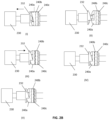
FIG. 3A depicts a perspective view of the first sampler of the effector arm in a first mode of operation wherein the crawl is in a preparatory position before collection of samples. -
FIG. 3B depicts a perspective view when the tong member is partially extending to enclose the sample and crawl. -
FIG. 3C depicts a perspective view when the shovel of the first sampler ofFIG. 3A has collected samples and has rotated partially away from the non-terrestrial surface with a sample contained therein. -
FIG. 3D depicts a perspective view of the embodiment ofFIG. 3A when the shovel of the first sampler with a sample ready for extension of the tong. -
FIG. 4 depicts a perspective view when the shovel of the first sampler ofFIG. 1 is in the process of sample collection of a large unitary regolith sample. -
FIG. 5A depicts a perspective view showing a sample collected by the shovel of the first sampler in the process of depositing regolith into a container. -
FIG. 5B depicts a perspective view of the embodiment of the first sampler of the end effector ofFIG. 1 when the tong and crawl are separated from each other in preparation for engagement with the lid of a container. -
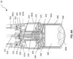
FIG. 6A depicts a partial sectional view of a second sampler of the end effector embodiment depicted inFIG. 1 in an initial state. -
FIG. 6B depicts a sectional view of the embodiment of the second sampler ofFIG. 1 when flaps are partially opened. -
FIG. 6C depicts a sectional view of the embodiment of the second sampler ofFIG. 1 when flaps are fully opened. -
FIG. 6D depicts a simplified sectional view of the embodiment of the flap actuating mechanism of the second sampler ofFIG. 6A . -
FIG. 6E depicts a simplified sectional view of the embodiment of the piston actuating mechanism of the second sampler ofFIG. 6A . -
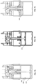
FIG. 7A depicts a cross sectional view of the embodiment of the second sampler of the end effector depicted inFIG. 1 when a piston is in an initial position. -
FIG. 7B depicts a cross sectional view of the embodiment of the second sampler of the end effector depicted inFIG. 1 when a piston is in a mid-position. -
FIG. 7C depicts a cross sectional view of the embodiment of the second sampler of the end effector depicted inFIG. 1 when a piston is in a fully retracted position. -
FIG. 7D depicts a partially enlarged perspective view of the second sampler of the end effector embodiment depicted inFIG. 1 . -
FIG. 7E depicts a cross sectional view of the second sampler of the end effector embodiment depicted inFIG. 1 showing a soft stop mechanism. -
FIG. 7F depicts a cross sectional view of the second sampler of the end effector embodiment depicted inFIG. 1 showing a piston actuating soft stop mechanism. -
FIG. 7G depicts a cross sectional view of the second sampler of the end effector embodiment depicted inFIG. 1 showing a flap extension/retraction "soft stop" mechanism. -
FIG. 8A depicts a perspective view when the second sampler of the end effector embodiment depicted inFIG. 1 is in a sample collection mode. -
FIG. 8B depicts a perspective view of the end effector embodiment depicted inFIG. 1 in sample deposition mode. -
FIG. 8C depicts a perspective view of the second sampler of the end effector embodiment depicted inFIG. 1 engaged with the lid of a container -
FIG. 9A depicts a perspective view of an exemplary camera of the end-effector system ofFIG. 1 . -
FIG. 9B depicts a perspective view of a thermal regulation member of the embodiment of the end-effector depicted inFIG. 1 . -
FIG. 9C depicts a cross sectional view of the thermal regulation member ofFIG. 9B . -
FIG. 9D depicts a cross sectional view showing a data transmission cable of the embodiment of the end-effector system depicted inFIG. 1 . - Referring to
FIG. 1 , there is depicted an exemplary perspective view of a robotic sampling assembly for non-terrestrial sampling according to a first embodiment of the present disclosure. As depicted, thesampling assembly 10 comprises a firstend effector assembly 20 and a secondend effector assembly 30. Also visible is theouter housing 50 offirst camera assembly 40 andsecond camera assembly 42. These camera assemblies are located on either side of thecentral axle 60 to which it would be appreciated an elongate arm may be attached (not shown). Rotation of the firstend effector assembly 20 and secondend effector assembly 30 about the central axle can be monitored by the attachedcamera assembly - Depending on the type of regolith sample which is to be collected, the sample may be collected using the first
end effector assembly 20 or the secondend effector assembly 30. It would be appreciated that for loose regularly sized small rocks/coarse-grained soil, the firstend effector assembly 20 is particularly useful as this type of material is easily collected by the mechanism depicted. Conversely for collecting regolith of fine-grained soil which is sticky, with semi-rigid dense and high strength, the secondend effector assembly 30 would be particularly useful, principally operating using a rotational coring type approach. - Now referring to
FIGS. 2A-2D , the firstend effector sampler 20 is discussed. As depicted, thefirst end sampler 20 comprises ascoop 210 and atong 220 for collecting regolith sample. Thescoop 210 is able to rotate aroundscoop axle 214 viaelongate member 212 for scooping up regolith samples from the ground. Thetong 220 is extendable from a retracted position wherein thetong 220 is received within a housing of thefirst end sampler 20 to an extended position in which thetong 220 fully extends over and encloses the cavity of thescoop 210. When covering the scoop the regolith sample is trapped inside thefirst end effector 20 and may be conveyed by the main arm (not shown) to a sample container 90 (e.g. depicted inFIG. 5A ). In addition thetong 220 may engage with the lip of the lid of thesample container 90 as depicted inFIG. 5B , to extract the sealed container from the sampling apparatus. - As would be appreciated by persons skilled in the art, an arrangement of multiple ratchet members such as that depicted in
FIG. 2D produces a range of vibrational movements, the amplitude of which is determined by the relative sizing and number of steps of adjacent ratchet members. Once the adjacent ratchets are engaged with each other, rotation of the motor drives the lead screw nut (and hence translates the tong) with no vibration. - The first
end effector sample 20 can provide the tong with three working modes, i.e., an extending mode, a rough vibration mode, a gentle vibration mode. - Referring particularly to
FIG. 2A , to extend thetong 220, afirst motor 230 drives apinon gear 232 coupled via a lead screw ratchet set 240 to drive alead screw 250. - When the tong is able to extend (without any rock jammed between the tong and the scoop), rotation of the
lead screw 250 drives leadnut 260 to translate along thelead screw 250. - Lateral movement of the
lead screw nut 260 along thelead screw 250 urges the attachedtong 220 in a direction of away from thefirst motor 230 to extend and cover the cavity of thescoop 210. (Accordingly, it would be appreciated that reversing the direction of rotation of the lead screw relative to the lead screw nut in turn retracts thetong 220 into the housing to uncover the cavity of the scoop 210). - The
stopper ratchet 240c is fixed at a predetermined lateral position in theend effector sample 20 and rotates together with thelead screw 250. Theintermediate ratchet 240b and the stopper ratchet 204c are engaged with each other and do not move apart from each other under normal operation. - The
tong 220 may become stuck, for example by being urged against regolith (e.g. a rock) projecting out of the scoop during as it is extending over the scoop. As there is no other means to clear the rock from the tong (e.g. no other person or other mechanism will be nearby) it is critical to provide a mechanism to produce a "juddering" mechanism which vibrationally shakes thetong 220 to clear any blocking regolith. - These vibrations of the
tong 220 are provided by coupling thefirst motor 230 via apinion gear 232 to a ratchet set 240 (including alead screw ratchet 240a, anintermediate ratchet 240b and astopper ratchet 240c) as shown in detail inFIG. 2B . - A "big jolt" would only be triggered when the
tong 220 and connectedlead screw ratchet 240a is forced to stop due to getting stuck while themotor 230 keeps rotating in normal direction thepinion gear 232. - When the extension of the tong is blocked by a regolith, the force applied on the
tong 220 exceeds a predetermined threshold value. Detection of this value causes the motor to reverse direction, pulling thepinion gear 232 away from thelead screw ratchet 240a as depicted in (I) and (II) ofFIG. 2B . - When the
first motor 230 drives thepinion gear 232 to rotate in normal direction, the face of thepinion gear 232 which includes a large step and an inclined surface is urged into engagement with a corresponding surface on thelead screw ratchet 240a under biasing forces provided by a resiliently deformable member (e.g. spring). This resiliently deformable member (not shown) may be located within the housing of thepinion gear 232 so as to urge the ratchet set 240 together, as depicted in (III) ofFIG. 2B . - In the gentle vibration mode, the
intermediate ratchet 240b is locked by thestopper ratchet 240c and therefore is not able to rotate withlead screw ratchet 240a. Thelead screw ratchet 240a and theintermediate ratchet 240b are able to disengage from each other while thelead screw ratchet 240a and thepinion 232 are engaged as depicted in (III) ofFIG. 2B . - Similarity, via the spring located within the housing of the
pinion 232, the rotation of the pinion 232 (and thelead screw ratchet 240a) can urge the surface oflead screw ratchet 240a to jump into a corresponding shoulder formed as shown in the mating surface of theintermediate ratchet 240b, which provides a gentler vibration of the lead screw, as depicted in (IV) ofFIG. 2B . - It depicts the
motor 230 rotates in the reverse direction and drives thepinion gear 232 to couple withlead screw ratchet 240a which in turn couples with the adjacentintermediate ratchet 240b so that all the three components (232, 240a and 240b) rotates together in the reverse direction to retract thetong 220 and gentle vibration results due to the stepping with thestopper ratchet 240c. - Now referring
FIGS. 2A and2C , the rotational movement of thescoop 210 about thescoop axle 214 is implemented via asecond motor 270. As shown thesecond motor 270 drives apinion gear 272 which in turn rotates a bevelledintermediate gear 274. Rotation of the bevelled intermediate gear drives theswivel gear 276 to which thescoop arm 212 is attached. Thescoop arm 212 and attachedscoop 210 can then be rotated away from and towards thetong 220 as depicted inFIG. 2C . The same movement of thescoop 210 towards/away from thetong 220 can be used for the sample deposition as depictedFIG. 5A intosample container 90, or engagement with the lid of thesample container 90 depicted inFIG. 5B . As depicted inFIG. 2D , thescoop 210 can be configured with atoothed edge 216 for facilitating collection of regolith. -
FIGS. 3A and3B show various positions of thescoop 210 relative to theend effector 20 for collection of regolith.FIGS. 3C and3D show exemplary positions of thetong 220 extending over collected sample to partially enclose this sample as described above. -
FIG. 4 depicts an alternate mode of operation in which theend effector 20 is inclined relative to the surface for capturing the scoop 210 a portion of projecting regolith. This sampling operations proceeds via the coordinated action of thescoop 210 andtong 220 of thefirst end effector 20 as described above, using a combination of rotation of thescoop 210 and extension of thetong 220. -
FIG. 5A depicts thescoop 210 rotating away from thetong 220 of thefirst end effector 20 to deposit the regolith sample in thecontainer 90 in accordance with the operational principles described above. -
FIG. 5B depicts cooperation between thescoop 210 andtong 220 of thefirst end effector 20 to locate on the lip of the lid of a sealedsample container 90 for removal from the sampling assembly and transfer to the launch vehicle (not shown) for return to Earth. - Referring to
FIGS. 6A-6D , there is depicted an exemplary cross-sectional view of the secondend effector assembly 30 according to an embodiment of the present disclosure, in relation to which the mechanisms for extension and retraction offlaps 304 and for movement of a piston member are described. -
Multiple flaps 304a, 304b, 304c, 304d, 304e, 304f, 304g, 304h (collectively as 304, a selection only being depicted) extend from between the lower portion of theouter housing 302c as shown InFIG. 6A . These flaps are retained between the lower portion of theouter housing 302c and aninner chamber housing 308. The inner chamber housing contains a void 309 in which the regolith sample is received. The piston member includes a piston lead screw 370 (comprising or engaged with at least a portion of a piston shaft) and apiston head 330 located at the end of the piston shaft. - There are two main operational aspects of the second
end effector assembly 30 depicted inFIGS. 6A-6D ; first the extending and retracting flaps 304a-h for collecting the regolith sample and second the operation of thepiston head 330 to expel the regolith sample from thevoid 309 for deposition of a regolith sample into a sampling container (this sampling container is then returned back to earth in the launch vehicle for analysis). - In general, as will be described further herein, the second
end effector assembly 30 comprises anouter housing 302 made up of upper, middle andlower portions - The second
end effector assembly 30 comprises a flap actuating mechanism 300a and a piston actuating mechanism 300b. The fixedupper platform 320 is rotatable around a fixed height of theupper housing 302a; anupper platform 320 attaches the secondend effector sampler 30 to a robot arm (not shown). Outer ball bearings 322 (respectively referred to as 322a and 322b) are for isolating the relative rotation between theouter housing 302 and theupper platform 320. Innerupper ball bearings 323 and innerintermediate ball bearings 325 are used to isolate the rotation of theupper platform 320 from the rotation of afirst lead screw 316 of the flap actuating mechanism 300a. - Referring to
FIGS. 6A-6D athird motor 310 is rotatably coupled with apinion gear 312. The teeth of thepinion gear 312 mesh with upper teeth ofintermediate gear 314. Hence, rotation of thethird motor 310 in either clockwise or anticlockwise directions rotates theintermediate gear 314 and in turn rotates the toothed portion of theflap lead screw 316 which is disposed external of the movable piston member. Theflap lead screw 316 extends down from the fixedupper platform support 320 into the rotatablemiddle portion 302b of the outer housing. - The
flap lead nut 326 is movably driven by theflap lead screw 316 to rotate about thelead screw 316; thereby moving up and down within themiddle portion 302b of theouter housing 302. - As the flap lead screw is attached to the
flap holder 340, the position of the flap holder relative to the middle portion of the outer housing also changes. Specifically, rotation of the lead screw in turn drives the lead nut which in turn translates theflap holder 340 upwardly from the position depicted inFIG. 6A through the position depicted inFIG. 6B to the final position depicted inFIG. 6C . - As the flaps 304a-h are attached with the
flap holder 340, the translation of the flap holder upwards as depicted inFIGS. 6A to 6D also moves the flaps 304a-h upwards; retracting the flaps into recesses (not shown) between theinner housing 308 and theouter housing 302, especially 302c.FIG. 6D depicts a simplified sectional view of the embodiment of the second sampler ofFIG. 6D without theoutside housing 302c and the piston actuating mechanism for movement of thepiston head 330 via translation of the attachedpiston shaft 370. - As would be appreciated by persons skilled in the art, reversing the direction of rotation the
third motor 310 in turn reverses the direction of rotation of thelead screw 316 and hence reverses the direction of travel of theflap lead nut 326 inside theouter housing 302. In this way, the extension and retraction of the flaps during the sampling operation of the secondend effector assembly 30 is achieved. - When the second
end effector sampler 30 is actuated by the third motor 310 (flap extension/retraction) or the fourth motor 350 (piston moving upwardly and downwardly as will be discussed below), theupper platform 320 does not change in the relative position in theouter housing 302. - Referring now to
FIGS. 7A to 7C , during the sample deposition process, regolith sample which is contained in thevoid 309 of theinner chamber housing 308 is urged out of the void, into a sample container (not shown). - At launch, for maximum stability the
piston head 330 is in a fully down position, as depicted inFIG. 7A . After the flaps are in a fully open positon as described with reference toFIGS. 6A-6D , thepiston head 330 moves through the intermediate position depicted inFIG. 7B into a fully up position as depicted inFIG. 7C . Once sampling has occurred, to expel the regolith contained in thevoid 309, thepiston head 330 needs to move back to the fully down position depicted inFIG. 7A through the intermediate position ofFIG. 7B . - In order to achieve reliable upward and downward movement of the piston head as described, rotational motion of
fourth motor 350 is converted to translation of the piston head in thehousing 302c. Referring toFIG. 6A andFIG. 7D , translation of thepiston head 330 is driven by thefourth motor 350 via rotation of thesecond pinion gear 352, which in turn rotates the secondintermediate gear 354. - Rotation of the second
intermediate gear 354 rotates theouter ring gear 356 which is engaged with theouter housing 302 which in turn rotates relative to the motor via the outer ball bearings 322. - In detail, rotation of the
fourth motor 350 is coupled via asecond pinion gear 352 to drive rotation of the lower teeth of secondintermediate gear 354 to bear against theouter ring gear 356 which is affixed to the upper portion of theouter housing 302. - In this way, the
external housing 302 is driven to rotate relative to theupper platform assembly 320. Theouter ball bearings outer housing 302 from theupper platform 320. Theinner housing 308 has aplatform 380 which is attached to theouter housing 302. The rotation of theouter housing 302 drives theinner housing 308 to rotate. - The
upper ratchet housing 360 fixed on theplatform 380. Theratchet housing 360 contains anupper ratchet 374 which has a protrusion receivable in a corresponding recess on inner side wall of thehousing 360. Theupper ratchet 374 is thereby coupled with alower ratchet 376. - The rotation from the
outer housing 302 andinner housing 308 is transmitted to the upper ratchet housing 360 (which is in turn connected with the upper ratchet 374) which is capable of coupling with thelower ratchet 376. Thus the rotation of the outer housing results in translation of the lead screw 370 (piston shaft) which is connected to the piston head inside the housing. - Inner
lower ball bearings 324 are retained between theratchet housing 360 and theplatform 380 and isolate thelower ratchet 376 from the rotation of theplatform 380. - The
lower ratchet 376 has a protrusion which is receivable in a corresponding recess in theupper ratchet 374. Theupper ratchet 374 andlower ratchet 376 enable relative rotation and bouncing between the two parts while allowing transmission of torque to drive the lead screw. This torque drives rotation of thepiston lead screw 370 and converts to translation viasecond lead nut 364, retained on theupper platform 320. It would be appreciated that the relative position of thepiston lead nut 364 relative to the intermediateouter housing 302b does not change in height; although it rotates. - As the regolith may adhere to the surfaces of the moving parts (such as
piston head 330,inner chamber housing 308, and platform 380), the regolith adhering to the parts needs to be removed during the sample collection to provide smooth operation. - Jamming of the sampling apparatus on a regolith sample in the middle of the sampling process must be avoided as it could potentially jeopardise the success of the sampling mission as there is no possibility of human intervention. As a result, the sampling mission cannot be completed in the event of jamming.
- To prevent jamming due to regolith, a shaking operation is provided and starts by the rotation of the
ratchet housing 360 which transmits torque to rotate theupper ratchet 374 while thelower ratchet 376 gets stuck. Aspring 362, is provided in theratchet housing 360, which preloads the complementary inclined surfaces of theupper ratchet 374 against thelower ratchet 376 into engagement with each other. In normal operation, the rotation of the upper ratchet and the lower ratchet provide urge thespring 362 into compression. In order to remove the adhered regolith, thespring 362 urges the upper ratchet and the lower ratchet to jump downwardly so as to bump off the regolith adhered to the parts. - Rotation of the
piston lead screw 370 in thepiston lead nut 364 results in translation of the piston lead screw 370 (shaft) axially; which moves the attachedpiston head 330 axially within a portion of theinner housing 308, which is disposed in the lower portion of theouter housing 302. - A
tapered trigger member 372 is attached to the top end of thesecond lead screw 370 and moves with the translating ofpiston lead screw 370. - As shown in
FIG. 7E andFIG. 7F , when thepiston lead screw 370 and thepiston head 330 move upwards proximal to a limit position, a protrudingshoulder 373 of the taperedtrigger member 372 is brought near to a triggering position marked "A". Once theshoulder 373 reaches the triggering position, theshoulder 373 of the taperedtrigger member 372 actuates alimit switch 374 which is configured to break the circuit driving thefourth motor 350. Actuation of the limit switch in this way ensure the extremity of movement of thepiston lead screw 370 relative to theupper platform 320 can be reliably and quickly detected. - It would be appreciated that a similar limiting configuration of flap limit switch 378 (as shown in
FIG. 7G ) can be used for limiting the position of the flap lead nut 326 (as well as the attached flap holder 340) within the intermediateouter housing 302b. When theflap lead nut 326 and theflap holder 340 approach the limit position by rotating on theflap lead screw 316, theflap holder 340 approaches anactuator 377 of theflap limit switch 378. - Once the
holder 40 reaches the limit position, theactuator 377 operates the flap limit switch 378 (either mechanically, optically, magnetically, or similar as would be appreciated by persons skilled in the art). This switch may in turn be directly coupled (or indirectly coupled via a signal to a processor) to break the power circuit providing power to thethird motor 310; thereby stopping its operation. - It would be appreciated that even if the control centre on earth is in communication with the remote lander but, due to the time delay in signals travelling between the mission control and the remotely located lander, it is not possible to observe and/or control the operation of the regolith sampling device in a timely manner during its operations. Therefore it is critical that the operation of flap extension and piston extension mechanism are controlled independently within predetermined limits using the immediate information received from the position detecting/monitoring sensors.
- The operation of the position limit detecting sensors thus operate to stop the travel of the
flap lead nut 326 on theflap lead screw 316; and hence prevent any further retraction of the flaps/flap member. - As compared to physical mechanisms which may be used to limit the travel of the second lead screw 370 (the piston actuating mechanism) relative to the
upper platform 320 or theflap lead nut 326 on theflap lead screw 316; the respective sensors act as "soft" position limits. This arrangement provides buffer time and extra distance so that before arriving at any physical limit positions (e.g. traveling beyond the threads of the respective lead screw), the piston actuating mechanism and the flap actuating mechanism cease operation safely after power supply to the respective motor is cut-off. This cessation in operation is performed relatively smoothly, without abrupt impact that would damage the delicate part(s), as would be the result of a mechanical stop. -
FIGS. 8A to 8C depicts various operational functions which may be performed by the secondend effector sampler 30. - Specifically, as depicted in
FIG. 8A theflaps 304 are slightly protruding (although may also be fully extended) to assist with collection of sample regolith together with the rotation offlap holder 340 in the lower portion of theouter housing 302c. - As depicted in
FIG. 8B , once a suitable depth has been reached, the flaps may be retracted as shown and described above to close off thevoid 309; and as shown the secondend effector sampler 30 may be withdrawn from the sampling region by movement an arm (not shown) to which saidend effector sampler 30 is attached. - As depicted in
FIG. 8C , once the regolith sample has been deposited in thesampling container 90, and the lid 91 secured; the filled sampling container needs to be extracted from the landing craft and inserted into the space craft which will return the sample to Earth. This operation may be accomplished by engagement of theflaps 304 with a locating rim of the lid 91 as depicted. - Now referring to
FIG. 9A there is depicted a perspective view of an exemplary pair ofcameras housing 50 and on either side ofcentral axle 60 as shown. - Referring to
FIG. 9B thehousing 50 has been removed. An exemplary camera image acquisition device can be CCDs, CMOS, and thermal regulation members. - Advantageously, more than one thermoelectric coolers (TECs) can be used to utilise the Peltier effect which draws electric current and actively pump heat from a first surface (
cold surface hot surfaces - The
cold surfaces CMOS image sensors 392 andFPGAs 396. - The corresponding
hot surfaces - As is known in the art, a TEC has only two wires (i.e. 1 red and 1 black) to draw current from an electrical power supply to create a temperature difference between the hot side and cold side. The hot and cold sides are marked in
FIG. 9C . The TEC has many advantages for temperature regulation, providing a high accuracy and stability, fast response time, a wide set-point temperature range and at the same time provide a simple structural design without moving parts, small and lightweight, reliable, noise-free and environmentally friendly. - The thermal regulation member inside the camera is made up of lightweight but high stiffness and high thermal conductivity material to protect the fragile optics and electronics components while transfer the heat efficiently and effectively to the outer casing.
- Accordingly, a heat transfer path is provided to transfer heat generated from the heat sources via the TECs to the connected camera casing and then further transferred to the camera outer surface where it is released.
- As shown in
FIG. 9D , two sets ofdata transmission cables 397 of the two cameras are connected to an electronic tri-state switching device as a switch which enables automatic camera selection and a common communication bus for data communication in both directions. Since the device only needs one set of cables connected to the controller side, the total number of cables are significantly reduced and are able to pass through the very limited narrow internal routing passage in the robot arm which is provided, thereby minimising weight and size required. - The disclosure provides a more reliable regolith collecting system used remotely away from potential intervention in the case of malfunction (e.g. caused by regolith jamming in the various mechanisms or simply starting/stopping of various stages in the operation).
- Advantageously, the sensor based limit detection described herein enables smooth deceleration of moving components such as the flaps and piston mechanism. This avoids physical damage resulting from abrupt contact which could be caused if mechanical constraints were used to restrain movement beyond extremities of the desired range.
- It would be appreciated that if a mechanical stop were utilised, the motor may continue to provide power for some time after the extremities of travel have been exceeded. Mechanical stop arrangements therefore pose a significantly higher risk of jamming or mechanical failure, which cannot be rectified easily due to the remoteness of operation. Therefore such mechanical arrangements increase the risk that the regolith retrieval operation may fail.
- Accordingly, the "soft stop" configuration of an aspect of the present disclosure provides a more reliable system which significantly reduces the potential risks of jamming or malfunction as would be the case if alternative mechanical position limiting arrangements were utilised.
- In addition, the TEC described herein provides a high accuracy and stability, fast response time, a wide set-point temperature range and simple structural design without moving parts, and are small and lightweight, reliable, noise-free and environmentally friendly.
- The two sets of data transmission cables of the two cameras provide a high speed transmitting of image data. Accordingly, the above advantages individually and in combination contribute to a more reliable regolith sampling system without adding significant additional weight or volume.
- The above embodiments are described by way of example only. Many variations are possible without departing from the scope of the disclosure as defined in the appended claims.
Claims (15)
- A regolith sampling apparatus, comprising:a generally cylindrical outer housing extending about a longitudinal axis comprising upper, intermediate and lower housings;an inner housing received in said outer lower housing and comprising a circumferential wall defining a void therein, said inner housing being rotatable with the outer housing;a plurality of retractable flaps extending from between the inner housing and lower outer housing;a piston member comprising a piston shaft and a piston head disposed in the inner housing;a flap support member translatable along on a first threaded rod upon rotation thereof, said flap support member being coupled to said retractable flaps to urge said flaps into and out from the space between the inner housing and the lower housing upon translation of said flap support member on said threaded rod;an upper platform rotatably isolated and supported in the upper outer housing at a fixed height therein, said upper platform supporting a flap driving means rotatably coupled to the first threaded rod via a first gear train and a piston member driving means coupled to the outer housing for rotatably driving said outer housing about the upper platform,a lower platform fixedly attached to the circumferential wall of the inner housing and outer housing; said lower platform being rotatably coupled via a ratchet mechanism to a second threaded rod comprising at least a portion of the piston shaft; said second threaded rod supported on the lower platform by a threaded nut such that rotation of said lower platform translates the piston head within the lower housing;at least one position limit detecting sensor disposed in the upper housing positioned proximate to either a predetermined extremity of travel of the at least one or more of the second threaded rod for detection of translation thereof, or the flap support member; andsaid at least one position detecting sensor operably coupled to either the piston member driving means or flap driving means.
- The regolith sampling apparatus of claim 1, wherein at least one position limit detecting sensor is disposed in the upper housing positioned proximate to the predetermined extremity of travel of the second threaded rod for detection of translation thereof; and at least one position detecting sensor is disposed in the upper housing positioned proximate to a predetermined extremity of travel of the flap support member.
- The regolith sampling apparatus of claim 1, wherein at least one position limit detecting sensor is operably coupled to at least one of the piston member driving means or the flap driving means by one or more microprocessors configured to interrupt current flow upon actuation of the sensor.
- The regolith sampling apparatus of claim 1, wherein at least one position limit detecting sensor disposed in the upper housing is positioned proximate to the predetermined extremity of travel of the second threaded rod for detection of translation thereof and wherein the at least one position detecting sensor is actuated by detecting proximity of a protrusion on the second threaded rod.
- The regolith sampling apparatus of claim 1, wherein the at least one position limit detecting sensor disposed in the upper housing is positioned proximate to the predetermined extremity of travel of the flap support member for detection of translation thereof; and wherein said position detecting sensor is actuated by detecting proximity of a protrusion on the flap support member.
- The regolith sampling apparatus of claim 1, wherein if said flap driving means is configured to extend the flaps from the space between the inner housing and outer housing in a first rotational direction and reversing said rotational direction of said flap driving means retracts said flaps.
- The regolith sampling apparatus of claim 1, wherein if said piston driving means is configured to drive the piston to translate the piston away from the lower platform in a first rotation direction and reversing said rotational direction of piston driving means translates the piston toward the lower platform.
- The regolith sampling apparatus of claim 1, wherein the flap support member is translatable within the middle outer housing.
- The regolith sampling apparatus of claim 1, wherein the ratchet mechanism comprises a ratchet housing member supported on the lower platform and receiving an upper ratchet member biased into engagement with a lower ratchet member, the ratchet mechanism preferably includes a biasing member for urging the upper ratchet member into re-engagement with the lower ratchet member.
- The regolith sampling apparatus of claim 1, further including at least one or more imaging acquisition devices disposed on the regolith sampling apparatus for receiving images of the operation thereof, wherein said imaging acquisition devices include one or more thermoelectric coolers coupled thereto.
- The regolith sampling apparatus of claim 10, wherein a first and second image acquisition devices are attached proximal to the regolith sampling apparatus; and wherein said first image acquisition device and said second image acquisition device are coupled via a common switch and common data cable to a common processor.
- A regolith sampling arm comprising a first regolith sampling apparatus disposed at a first end and second regolith sampling apparatus disposed at a second end;said first regolith sampling apparatus comprising:a generally cylindrical outer housing extending about a longitudinal axis comprising upper, intermediate and lower housings,an inner housing received in said outer lower housing and comprising a circumferential wall defining a void therein, said inner housing being rotatable with the outer housing;a plurality of retractable flaps extending from between the inner housing and lower outer housing;a piston member comprising a shaft and a piston head disposed in the inner housing;a flap support member translatable along on a first threaded rod upon rotation thereof, said flap support member being coupled to said retractable flaps to urge said flaps into and out from the space between the inner housing and the lower housing upon translation of said flap support member on said threaded rod;an upper platform rotatably isolated and supported in the upper outer housing at a fixed height therein, said upper platform supporting a flap driving means rotatably coupled to the first threaded rod via a first gear train and a piston member driving means coupled to the outer housing for rotatably driving said outer housing about the upper platform,a lower platform fixedly attached to the circumferential wall of the inner housing and outer housing; said lower platform being rotatably coupled via a ratchet mechanism to a second threaded rod comprising at least a portion of the piston shaft; said second threaded rod supported on the lower platform by a threaded nut such that rotation of said lower platform translates the piston member within the middle and upper housing;at least one position detecting sensor disposed in the upper housing positioned proximate to either a predetermined extremity of travel of the at least one or more of the second threaded rod for detection of translation thereof, or the flap support member; andsaid at least one position detecting sensor operably coupled to either the piston driving means or flap driving means;said second regolith sampling apparatus comprising:a housing;a scoop member having a body for receiving regolith therein; said scoop member being rotatable about an axle of said housing upon actuation of a scoop motor disposed in said housing; andan extendable tong configured to substantially enclose regolith received in said scoop member upon actuation of a tong motor coupled to the tong via a ratchet mechanism disposed in said housing.
- The regolith sampling arm of claim 12, wherein at least one of the scoop member or the extendable tong includes a plurality of serrations on the edges thereof.
- The regolith sampling arm of claim 12 further comprising one or more image acquisition devices connected via one or more thermal regulation members to one or more thermo-electric coolers.
- The regolith sampling arm of claim 12 further comprising two or more image acquisition devices connected via a three state switching device with a controller.
Priority Applications (2)
| Application Number | Priority Date | Filing Date | Title |
|---|---|---|---|
| EP21212451.5A EP4191223B1 (en) | 2021-12-06 | 2021-12-06 | Regolith sampling apparatus and arm |
| PCT/CN2022/077364 WO2023103184A1 (en) | 2021-12-06 | 2022-02-23 | Regolith sampling apparatus and arm |
Applications Claiming Priority (1)
| Application Number | Priority Date | Filing Date | Title |
|---|---|---|---|
| EP21212451.5A EP4191223B1 (en) | 2021-12-06 | 2021-12-06 | Regolith sampling apparatus and arm |
Publications (3)
| Publication Number | Publication Date |
|---|---|
| EP4191223A1 true EP4191223A1 (en) | 2023-06-07 |
| EP4191223C0 EP4191223C0 (en) | 2024-09-11 |
| EP4191223B1 EP4191223B1 (en) | 2024-09-11 |
Family
ID=78821760
Family Applications (1)
| Application Number | Title | Priority Date | Filing Date |
|---|---|---|---|
| EP21212451.5A Active EP4191223B1 (en) | 2021-12-06 | 2021-12-06 | Regolith sampling apparatus and arm |
Country Status (2)
| Country | Link |
|---|---|
| EP (1) | EP4191223B1 (en) |
| WO (1) | WO2023103184A1 (en) |
Family Cites Families (6)
| Publication number | Priority date | Publication date | Assignee | Title |
|---|---|---|---|---|
| CN104062146B (en) * | 2014-06-20 | 2016-05-04 | 北京空间飞行器总体设计部 | Lunar soil cutting arrangement |
| CN105019825B (en) * | 2015-07-16 | 2018-01-30 | 北京航空航天大学 | A kind of drill configuration for including three kinds of drive mechanisms |
| US20200271682A1 (en) * | 2019-02-27 | 2020-08-27 | Alpha Space Test and Research Alliance, LLC | Systems and Methods for Environmental Factor Interaction Characterization |
| CN110455574B (en) * | 2019-08-29 | 2021-08-17 | 北京空间飞行器总体设计部 | A friction drive type extraterrestrial celestial body soil collection mechanism |
| CN111006897B (en) * | 2019-11-01 | 2022-10-21 | 北京空间飞行器总体设计部 | A shrapnel-type extraterrestrial body surface soil sampling mechanism and sampling method |
| CN113084795A (en) * | 2021-02-26 | 2021-07-09 | 北京空间飞行器总体设计部 | Visual measurement system and method applied to meter-taking sampling mechanical arm |
-
2021
- 2021-12-06 EP EP21212451.5A patent/EP4191223B1/en active Active
-
2022
- 2022-02-23 WO PCT/CN2022/077364 patent/WO2023103184A1/en not_active Ceased
Non-Patent Citations (5)
| Title |
|---|
| ??: "Hong Kong researchers help complete lunar sampling for Chang'e-5 - Chinadaily.com.cn", 18 December 2020 (2020-12-18), XP055920353, Retrieved from the Internet <URL:https://www.chinadaily.com.cn/a/202012/18/WS5fdc1710a31024ad0ba9c9ef_1.html> [retrieved on 20220511] * |
| ANONYMOUS: "PolyU develops space instruments for the Nation's first lunar sample return mission | The Hong Kong Polytechnic University", 24 November 2020 (2020-11-24), XP055920349, Retrieved from the Internet <URL:https://www.polyu.edu.hk/en/media/media-releases/2020/1124_polyu-develops-space-instruments-for-the-nations-first-lunar-sample-return-mission/> [retrieved on 20220511] * |
| ANONYMOUS: "PolyU-developed space instruments complete lunar sampling for Chang'e 5 | Mainland Development Office", 22 February 2021 (2021-02-22), XP055920351, Retrieved from the Internet <URL:https://www.polyu.edu.hk/mdo/news-and-events/2020/20201208/> [retrieved on 20220511] * |
| ANONYMOUS: "PolyU-developed space instruments complete lunar sampling for Chang'e 5 | The Hong Kong Polytechnic University", 8 December 2020 (2020-12-08), XP055920352, Retrieved from the Internet <URL:https://www.polyu.edu.hk/en/media/media-releases/2020/1208_polyu_space_instruments_complete_lunar_sampling_for_chang_e-5/> [retrieved on 20220511] * |
| THE HONG KONG POLYTECHNIC UNIVERSITY: "Space Exploration - PolyU's Surface Sampling and Packing System", 29 December 2020 (2020-12-29), XP055920348, Retrieved from the Internet <URL:https://www.youtube.com/watch?v=D1uNKNuYjfc> [retrieved on 20220511] * |
Also Published As
| Publication number | Publication date |
|---|---|
| WO2023103184A1 (en) | 2023-06-15 |
| EP4191223C0 (en) | 2024-09-11 |
| EP4191223B1 (en) | 2024-09-11 |
Similar Documents
| Publication | Publication Date | Title |
|---|---|---|
| CN108613831B (en) | Lunar surface sampling mechanical arm | |
| US6837312B2 (en) | Corer-grinder | |
| EP4191223B1 (en) | Regolith sampling apparatus and arm | |
| FR2611181A1 (en) | SYSTEM FOR EXECUTING AN ACTIVITY IN SPACE | |
| CN107966315B (en) | A kind of celestial body surface sampling apparatus | |
| CN112350214A (en) | High-altitude line inspection robot | |
| CN111366396B (en) | Small celestial body integrated sampler with grinding and clamping functions | |
| JP2017098816A (en) | Cleaning device, monitor camera including cleaning device, and control device for the same | |
| CN109176450B (en) | Master-slave robot system | |
| CN111587665B (en) | Four-degree-of-freedom multi-eye visual rotary-flying picking robot and picking method thereof | |
| CN109592059A (en) | Modularized multifunctional unmanned aerial vehicle acquisition device | |
| CN113092158A (en) | Drilling and surface heterogeneous sampling system and method for extraterrestrial celestial body | |
| CN109204836A (en) | A kind of unmanned plane air crash protective device | |
| CN102507253B (en) | End effector for planetary sample collection and recovery | |
| CN114837500A (en) | Novel automobile door lock with electric flexible opening branched chain and electric suction branched chain | |
| CN110455574B (en) | A friction drive type extraterrestrial celestial body soil collection mechanism | |
| CN112205918B (en) | Dust collecting device and dust collecting system with same | |
| Kubota et al. | Japanese lunar robotics exploration by co-operation with lander and rover | |
| Inazawa et al. | Autonomous Control of Lunar Excursion Vehicle 2 (LEV-2) | |
| EP4248287A1 (en) | Method and apparatus for obtaining observation data of an environment | |
| CN115561016B (en) | Shallow surface layer order-preserving sampling recovery system for extra-terrestrial planet non-consolidated star soil | |
| EP4105631A1 (en) | Regolith packaging system and container with lid | |
| CN113899581B (en) | Trigger grabbing type multi-cavity sampling mechanism | |
| CN216035099U (en) | A surveying and mapping equipment protection seat for aerial survey drone landing | |
| CN117145484A (en) | Anchor device and star soil tunneling robot |
Legal Events
| Date | Code | Title | Description |
|---|---|---|---|
| PUAI | Public reference made under article 153(3) epc to a published international application that has entered the european phase |
Free format text: ORIGINAL CODE: 0009012 |
|
| STAA | Information on the status of an ep patent application or granted ep patent |
Free format text: STATUS: REQUEST FOR EXAMINATION WAS MADE |
|
| 17P | Request for examination filed |
Effective date: 20221122 |
|
| AK | Designated contracting states |
Kind code of ref document: A1 Designated state(s): AL AT BE BG CH CY CZ DE DK EE ES FI FR GB GR HR HU IE IS IT LI LT LU LV MC MK MT NL NO PL PT RO RS SE SI SK SM TR |
|
| GRAP | Despatch of communication of intention to grant a patent |
Free format text: ORIGINAL CODE: EPIDOSNIGR1 |
|
| STAA | Information on the status of an ep patent application or granted ep patent |
Free format text: STATUS: GRANT OF PATENT IS INTENDED |
|
| RIC1 | Information provided on ipc code assigned before grant |
Ipc: G01N 1/08 20060101ALN20240318BHEP Ipc: G01N 33/24 20060101ALN20240318BHEP Ipc: E21C 51/00 20060101ALI20240318BHEP Ipc: G01N 1/04 20060101AFI20240318BHEP |
|
| INTG | Intention to grant announced |
Effective date: 20240410 |
|
| GRAS | Grant fee paid |
Free format text: ORIGINAL CODE: EPIDOSNIGR3 |
|
| GRAA | (expected) grant |
Free format text: ORIGINAL CODE: 0009210 |
|
| STAA | Information on the status of an ep patent application or granted ep patent |
Free format text: STATUS: THE PATENT HAS BEEN GRANTED |
|
| AK | Designated contracting states |
Kind code of ref document: B1 Designated state(s): AL AT BE BG CH CY CZ DE DK EE ES FI FR GB GR HR HU IE IS IT LI LT LU LV MC MK MT NL NO PL PT RO RS SE SI SK SM TR |
|
| REG | Reference to a national code |
Ref country code: GB Ref legal event code: FG4D |
|
| REG | Reference to a national code |
Ref country code: CH Ref legal event code: EP |
|
| REG | Reference to a national code |
Ref country code: DE Ref legal event code: R096 Ref document number: 602021018605 Country of ref document: DE |
|
| REG | Reference to a national code |
Ref country code: IE Ref legal event code: FG4D |
|
| U01 | Request for unitary effect filed |
Effective date: 20241009 |
|
| U07 | Unitary effect registered |
Designated state(s): AT BE BG DE DK EE FI FR IT LT LU LV MT NL PT RO SE SI Effective date: 20241029 |
|
| PG25 | Lapsed in a contracting state [announced via postgrant information from national office to epo] |
Ref country code: NO Free format text: LAPSE BECAUSE OF FAILURE TO SUBMIT A TRANSLATION OF THE DESCRIPTION OR TO PAY THE FEE WITHIN THE PRESCRIBED TIME-LIMIT Effective date: 20241211 |
|
| PG25 | Lapsed in a contracting state [announced via postgrant information from national office to epo] |
Ref country code: GR Free format text: LAPSE BECAUSE OF FAILURE TO SUBMIT A TRANSLATION OF THE DESCRIPTION OR TO PAY THE FEE WITHIN THE PRESCRIBED TIME-LIMIT Effective date: 20241212 |
|
| PG25 | Lapsed in a contracting state [announced via postgrant information from national office to epo] |
Ref country code: HR Free format text: LAPSE BECAUSE OF FAILURE TO SUBMIT A TRANSLATION OF THE DESCRIPTION OR TO PAY THE FEE WITHIN THE PRESCRIBED TIME-LIMIT Effective date: 20240911 |
|
| PG25 | Lapsed in a contracting state [announced via postgrant information from national office to epo] |
Ref country code: RS Free format text: LAPSE BECAUSE OF FAILURE TO SUBMIT A TRANSLATION OF THE DESCRIPTION OR TO PAY THE FEE WITHIN THE PRESCRIBED TIME-LIMIT Effective date: 20241211 Ref country code: ES Free format text: LAPSE BECAUSE OF FAILURE TO SUBMIT A TRANSLATION OF THE DESCRIPTION OR TO PAY THE FEE WITHIN THE PRESCRIBED TIME-LIMIT Effective date: 20240911 |
|
| PG25 | Lapsed in a contracting state [announced via postgrant information from national office to epo] |
Ref country code: RS Free format text: LAPSE BECAUSE OF FAILURE TO SUBMIT A TRANSLATION OF THE DESCRIPTION OR TO PAY THE FEE WITHIN THE PRESCRIBED TIME-LIMIT Effective date: 20241211 Ref country code: NO Free format text: LAPSE BECAUSE OF FAILURE TO SUBMIT A TRANSLATION OF THE DESCRIPTION OR TO PAY THE FEE WITHIN THE PRESCRIBED TIME-LIMIT Effective date: 20241211 Ref country code: HR Free format text: LAPSE BECAUSE OF FAILURE TO SUBMIT A TRANSLATION OF THE DESCRIPTION OR TO PAY THE FEE WITHIN THE PRESCRIBED TIME-LIMIT Effective date: 20240911 Ref country code: GR Free format text: LAPSE BECAUSE OF FAILURE TO SUBMIT A TRANSLATION OF THE DESCRIPTION OR TO PAY THE FEE WITHIN THE PRESCRIBED TIME-LIMIT Effective date: 20241212 Ref country code: ES Free format text: LAPSE BECAUSE OF FAILURE TO SUBMIT A TRANSLATION OF THE DESCRIPTION OR TO PAY THE FEE WITHIN THE PRESCRIBED TIME-LIMIT Effective date: 20240911 |
|
| U20 | Renewal fee for the european patent with unitary effect paid |
Year of fee payment: 4 Effective date: 20241230 |
|
| PG25 | Lapsed in a contracting state [announced via postgrant information from national office to epo] |
Ref country code: IS Free format text: LAPSE BECAUSE OF FAILURE TO SUBMIT A TRANSLATION OF THE DESCRIPTION OR TO PAY THE FEE WITHIN THE PRESCRIBED TIME-LIMIT Effective date: 20250111 |
|
| PG25 | Lapsed in a contracting state [announced via postgrant information from national office to epo] |
Ref country code: SM Free format text: LAPSE BECAUSE OF FAILURE TO SUBMIT A TRANSLATION OF THE DESCRIPTION OR TO PAY THE FEE WITHIN THE PRESCRIBED TIME-LIMIT Effective date: 20240911 |
|
| PG25 | Lapsed in a contracting state [announced via postgrant information from national office to epo] |
Ref country code: CZ Free format text: LAPSE BECAUSE OF FAILURE TO SUBMIT A TRANSLATION OF THE DESCRIPTION OR TO PAY THE FEE WITHIN THE PRESCRIBED TIME-LIMIT Effective date: 20240911 Ref country code: PL Free format text: LAPSE BECAUSE OF FAILURE TO SUBMIT A TRANSLATION OF THE DESCRIPTION OR TO PAY THE FEE WITHIN THE PRESCRIBED TIME-LIMIT Effective date: 20240911 |
|
| PG25 | Lapsed in a contracting state [announced via postgrant information from national office to epo] |
Ref country code: SK Free format text: LAPSE BECAUSE OF FAILURE TO SUBMIT A TRANSLATION OF THE DESCRIPTION OR TO PAY THE FEE WITHIN THE PRESCRIBED TIME-LIMIT Effective date: 20240911 |
|
| PG25 | Lapsed in a contracting state [announced via postgrant information from national office to epo] |
Ref country code: MC Free format text: LAPSE BECAUSE OF FAILURE TO SUBMIT A TRANSLATION OF THE DESCRIPTION OR TO PAY THE FEE WITHIN THE PRESCRIBED TIME-LIMIT Effective date: 20240911 |
|
| PLBE | No opposition filed within time limit |
Free format text: ORIGINAL CODE: 0009261 |
|
| STAA | Information on the status of an ep patent application or granted ep patent |
Free format text: STATUS: NO OPPOSITION FILED WITHIN TIME LIMIT |
|
| REG | Reference to a national code |
Ref country code: CH Ref legal event code: PL |
|
| 26N | No opposition filed |
Effective date: 20250612 |
|
| PG25 | Lapsed in a contracting state [announced via postgrant information from national office to epo] |
Ref country code: CH Free format text: LAPSE BECAUSE OF NON-PAYMENT OF DUE FEES Effective date: 20241231 |
|
| PG25 | Lapsed in a contracting state [announced via postgrant information from national office to epo] |
Ref country code: IE Free format text: LAPSE BECAUSE OF NON-PAYMENT OF DUE FEES Effective date: 20241206 |
|
| U20 | Renewal fee for the european patent with unitary effect paid |
Year of fee payment: 5 Effective date: 20251230 |
|
| PG25 | Lapsed in a contracting state [announced via postgrant information from national office to epo] |
Ref country code: CY Free format text: LAPSE BECAUSE OF FAILURE TO SUBMIT A TRANSLATION OF THE DESCRIPTION OR TO PAY THE FEE WITHIN THE PRESCRIBED TIME-LIMIT; INVALID AB INITIO Effective date: 20211206 |