EP4191187A1 - Partitioning member for total heat exchange elements, total heat exchange element, and ventilation apparatus - Google Patents
Partitioning member for total heat exchange elements, total heat exchange element, and ventilation apparatus Download PDFInfo
- Publication number
- EP4191187A1 EP4191187A1 EP21875468.7A EP21875468A EP4191187A1 EP 4191187 A1 EP4191187 A1 EP 4191187A1 EP 21875468 A EP21875468 A EP 21875468A EP 4191187 A1 EP4191187 A1 EP 4191187A1
- Authority
- EP
- European Patent Office
- Prior art keywords
- heat exchange
- total heat
- exchange element
- moisture permeable
- permeable membrane
- Prior art date
- Legal status (The legal status is an assumption and is not a legal conclusion. Google has not performed a legal analysis and makes no representation as to the accuracy of the status listed.)
- Granted
Links
Images






Classifications
-
- F—MECHANICAL ENGINEERING; LIGHTING; HEATING; WEAPONS; BLASTING
- F28—HEAT EXCHANGE IN GENERAL
- F28F—DETAILS OF HEAT-EXCHANGE AND HEAT-TRANSFER APPARATUS, OF GENERAL APPLICATION
- F28F21/00—Constructions of heat-exchange apparatus characterised by the selection of particular materials
-
- F—MECHANICAL ENGINEERING; LIGHTING; HEATING; WEAPONS; BLASTING
- F28—HEAT EXCHANGE IN GENERAL
- F28D—HEAT-EXCHANGE APPARATUS, NOT PROVIDED FOR IN ANOTHER SUBCLASS, IN WHICH THE HEAT-EXCHANGE MEDIA DO NOT COME INTO DIRECT CONTACT
- F28D9/00—Heat-exchange apparatus having stationary plate-like or laminated conduit assemblies for both heat-exchange media, the media being in contact with different sides of a conduit wall
- F28D9/0062—Heat-exchange apparatus having stationary plate-like or laminated conduit assemblies for both heat-exchange media, the media being in contact with different sides of a conduit wall the conduits for one heat-exchange medium being formed by spaced plates with inserted elements
-
- F—MECHANICAL ENGINEERING; LIGHTING; HEATING; WEAPONS; BLASTING
- F24—HEATING; RANGES; VENTILATING
- F24F—AIR-CONDITIONING; AIR-HUMIDIFICATION; VENTILATION; USE OF AIR CURRENTS FOR SCREENING
- F24F7/00—Ventilation
- F24F7/04—Ventilation with ducting systems, e.g. by double walls; with natural circulation
-
- F—MECHANICAL ENGINEERING; LIGHTING; HEATING; WEAPONS; BLASTING
- F28—HEAT EXCHANGE IN GENERAL
- F28D—HEAT-EXCHANGE APPARATUS, NOT PROVIDED FOR IN ANOTHER SUBCLASS, IN WHICH THE HEAT-EXCHANGE MEDIA DO NOT COME INTO DIRECT CONTACT
- F28D21/00—Heat-exchange apparatus not covered by any of the groups F28D1/00 - F28D20/00
- F28D21/0015—Heat and mass exchangers, e.g. with permeable walls
-
- F—MECHANICAL ENGINEERING; LIGHTING; HEATING; WEAPONS; BLASTING
- F28—HEAT EXCHANGE IN GENERAL
- F28D—HEAT-EXCHANGE APPARATUS, NOT PROVIDED FOR IN ANOTHER SUBCLASS, IN WHICH THE HEAT-EXCHANGE MEDIA DO NOT COME INTO DIRECT CONTACT
- F28D9/00—Heat-exchange apparatus having stationary plate-like or laminated conduit assemblies for both heat-exchange media, the media being in contact with different sides of a conduit wall
- F28D9/0025—Heat-exchange apparatus having stationary plate-like or laminated conduit assemblies for both heat-exchange media, the media being in contact with different sides of a conduit wall the conduits being formed by zig-zag bend plates
-
- F—MECHANICAL ENGINEERING; LIGHTING; HEATING; WEAPONS; BLASTING
- F28—HEAT EXCHANGE IN GENERAL
- F28F—DETAILS OF HEAT-EXCHANGE AND HEAT-TRANSFER APPARATUS, OF GENERAL APPLICATION
- F28F3/00—Plate-like or laminated elements; Assemblies of plate-like or laminated elements
- F28F3/08—Elements constructed for building-up into stacks, e.g. capable of being taken apart for cleaning
-
- F—MECHANICAL ENGINEERING; LIGHTING; HEATING; WEAPONS; BLASTING
- F28—HEAT EXCHANGE IN GENERAL
- F28F—DETAILS OF HEAT-EXCHANGE AND HEAT-TRANSFER APPARATUS, OF GENERAL APPLICATION
- F28F2245/00—Coatings; Surface treatments
- F28F2245/02—Coatings; Surface treatments hydrophilic
-
- F—MECHANICAL ENGINEERING; LIGHTING; HEATING; WEAPONS; BLASTING
- F28—HEAT EXCHANGE IN GENERAL
- F28F—DETAILS OF HEAT-EXCHANGE AND HEAT-TRANSFER APPARATUS, OF GENERAL APPLICATION
- F28F2265/00—Safety or protection arrangements; Arrangements for preventing malfunction
- F28F2265/20—Safety or protection arrangements; Arrangements for preventing malfunction for preventing development of microorganisms
-
- Y—GENERAL TAGGING OF NEW TECHNOLOGICAL DEVELOPMENTS; GENERAL TAGGING OF CROSS-SECTIONAL TECHNOLOGIES SPANNING OVER SEVERAL SECTIONS OF THE IPC; TECHNICAL SUBJECTS COVERED BY FORMER USPC CROSS-REFERENCE ART COLLECTIONS [XRACs] AND DIGESTS
- Y02—TECHNOLOGIES OR APPLICATIONS FOR MITIGATION OR ADAPTATION AGAINST CLIMATE CHANGE
- Y02B—CLIMATE CHANGE MITIGATION TECHNOLOGIES RELATED TO BUILDINGS, e.g. HOUSING, HOUSE APPLIANCES OR RELATED END-USER APPLICATIONS
- Y02B30/00—Energy efficient heating, ventilation or air conditioning [HVAC]
- Y02B30/56—Heat recovery units
Definitions
- the present disclosure relates to a partitioning member for a total heat exchange element, a total heat exchange element including the partitioning member, and a ventilation device including the total heat exchange element.
- a ventilation device including a heat exchange element As disclosed in Patent Document 1, a ventilation device including a heat exchange element has been known.
- the heat exchange element exchanges heat between supply air and exhaust air.
- Patent Document 1 Japanese Unexamined Patent Publication No. 2011-163650
- the adhesive containing the antibacterial/antifungal component is provided at a portion where the flat plate-shaped partitioning member and the corrugated plate-shaped spacing member contact each other.
- growth of bacteria and fungi cannot be reduced at portions of the partitioning member and the spacing member not in contact with the adhesive.
- a first aspect of the present disclosure is directed to a partitioning member (40) for a total heat exchange element.
- the partitioning member (40) includes a sheet-shaped porous base (41), a moisture permeable membrane (42) provided on the porous base (41), and a functional material (46) producing at least one of an antifungal effect, an antibacterial effect, or an antiviral effect, the moisture permeable membrane (42) containing the functional material (46).
- the moisture permeable membrane (42) containing the functional material (46) is provided on the sheet-shaped porous base (41).
- the partitioning member (40) for the total heat exchange element can be kept clean.
- a second aspect of the present disclosure is an embodiment of the first aspect.
- the functional material (46) is smaller than a thickness of the moisture permeable membrane (42).
- the functional material (46) smaller than the thickness of the moisture permeable membrane (42) is provided in the moisture permeable membrane (42).
- a third aspect of the present disclosure is directed to a partitioning member (40) for a total heat exchange element.
- the partitioning member (40) includes a sheet-shaped porous base (41), a moisture permeable membrane (42) provided on the porous base (41), and a functional membrane (45) containing a functional material (46) producing at least one of an antifungal effect, an antibacterial effect, or an antiviral effect and covering a surface of the porous base (41) or the moisture permeable membrane (42).
- the functional membrane (45) containing the functional material (46) is provided for the partitioning member (40) for the total heat exchange element.
- the partitioning member (40) for the total heat exchange element can be kept clean.
- a fourth aspect of the present disclosure is an embodiment of the third aspect.
- the functional membrane (45) is thinner than the moisture permeable membrane (42).
- the functional membrane (45) is thinner than the moisture permeable membrane (42).
- a decrease in the heat exchange amount due to the provision of the functional membrane (45) in the partitioning member (40) for the total heat exchange element is reduced.
- a fifth aspect of the present disclosure is an embodiment of any one of the first to fourth aspects.
- the moisture permeable membrane (42) is provided so as to cover a surface of the porous base (41), and the surface of the porous base (41) covered with the moisture permeable membrane (42) is subjected to hydrophilic treatment.
- the porous base (41) is subjected to the hydrophilic treatment.
- a process of forming the moisture permeable membrane (42) on the surface of the porous base (41) is facilitated.
- a sixth aspect of the present disclosure is an embodiment of any one of the first to fifth aspects.
- the functional material (46) is a substance containing pyrithione in a molecular structure.
- the substance containing pyrithione in its molecular structure is provided as the functional material (46) in the partitioning member (40) for the total heat exchange element.
- a seventh aspect of the present disclosure is directed to a total heat exchange element (30).
- the total heat exchange element (30) includes a plurality of partitioning members (40) of any one of the first to sixth aspects, and a spacing member (32, 125, 155) arranged between adjacent ones of the partitioning members (40) stacked, the spacing member (32, 125, 155) keeping a distance between the adjacent partitioning members (40), a first air flow path (36, 121) and a second air flow path (37, 151) being alternately provided with an associated one of the partitioning members (40) interposed therebetween.
- the total heat exchange element (30) includes a plurality of partitioning members (40) of any one of the first to sixth aspects.
- An eighth aspect of the present disclosure is directed to a ventilation device (10).
- the ventilation device (10) includes the total heat exchange element (30) of the seventh aspect.
- Supply air to be supplied from an outdoor space to an indoor space flows in the first air flow path (36, 121) of the total heat exchange element (30), and exhaust air to be discharged from the indoor space to the outdoor space flows in the second air flow path (37, 151) of the total heat exchange element (30).
- the ventilation device (10) includes the total heat exchange element (30) of the seventh aspect.
- This embodiment relates to a partitioning member (40) for a total heat exchange element.
- the partitioning member (40) for the total heat exchange element according to this embodiment forms a total heat exchange element (30) provided for a ventilation device (10).
- the partitioning member (40) for the total heat exchange element according to this embodiment is a member for causing exchange of sensible heat and latent heat (moisture) between supply air and exhaust air.
- the "partitioning member for the total heat exchange element" will be simply referred to as a “partitioning member.”
- the partitioning member (40) of this embodiment includes a sheet-shaped porous base (41) and a moisture permeable membrane (42) provided on the porous base (41).
- the moisture permeable membrane (42) is provided to cover a first surface (41a) of the porous base (41), which is one of surfaces of the porous base (41).
- the porous base (41) is a porous sheet-shaped member made of polyolefin-based resin, for example.
- the porous base (41) may be non-woven fabric made of fibrous resin.
- the porous base (41) has a thickness of 10 ⁇ m, for example.
- the porous base (41) is an element that serves as a support for the moisture permeable membrane (42), and has high moisture permeability.
- the first surface (41a), i.e., one of the surfaces of the porous base (41), is subjected to hydrophilic treatment.
- hydrophilic treatment include corona discharge treatment and plasma treatment.
- the hydrophilic treatment allows generation of a carboxy group, a hydroxy group, or a carbonyl group on the first surface (41a) of the porous base (41).
- the moisture permeable membrane (42) is a coating covering the entirety of the first surface (41a) of the porous base (41).
- the moisture permeable membrane (42) is made of a polymer having moisture permeability.
- the polymer forming the moisture permeable membrane (42) is copolymer having a first constitutional unit and a second constitutional unit.
- the moisture permeable membrane (42) has a thickness of 1 ⁇ m, for example.
- the thickness of the moisture permeable membrane (42) is not particularly limited, and is preferably 0.05 ⁇ m to 1 ⁇ m and more preferably 0.1 ⁇ m to 0.5 ⁇ m. In a case where the thickness of the moisture permeable membrane (42) is 0.05 ⁇ m or more, favorable film formability is exhibited, leading to improvement in gas barrier properties. In a case where the above-described thickness is 1 ⁇ m or less, more favorable moisture permeability is exhibited.
- Examples of monomer forming the first constitutional unit may include 2-methacryloyloxyethyl phosphorylcholine.
- Examples of monomer forming the second constitutional unit may include (meth)acrylic acid alkyl ester having an alkyl group with a carbon number of 2 or more in an ester moiety, such as (meth)acrylic acid stearyl.
- the form of copolymer having the first constitutional unit and the second constitutional unit is not particularly limited, and the copolymer forming the moisture permeable membrane (42) may be any of a block copolymer, an alternating copolymer, and a random copolymer.
- the moisture permeable membrane (42) contains a functional material (46) producing an antifungal effect and an antibacterial effect.
- the moisture permeable membrane (42) of this embodiment contains sodium pyrithione (C 5 H 4 NNaOS) as the functional material (46). Molecules of sodium pyrithione, which is the functional material (46), are dispersed in the moisture permeable membrane (42).
- the size (the van der Waals radius in this embodiment) of the functional material (46) contained in the moisture permeable membrane (42) is 5 nm or less and less than the thickness (about 1 ⁇ m) of the moisture permeable membrane (42).
- a step of forming the moisture permeable membrane (42) on the porous base (41) includes an application step of applying a composition for forming the moisture permeable membrane (42) to the first surface (41a) of the porous base (41) and a drying step of heating a coating formed in the application step and evaporating a solvent.
- the composition used in the application step is obtained by dissolving or dispersing the above-described copolymer and the functional material (46) in the solvent such as water.
- the first surface (41a) of the porous base (41), to which surface the composition is applied in the application step, is subjected to the hydrophilic treatment in advance. Thus, the thickness of the coating formed on the first surface (41a) becomes uniform.
- the moisture permeable membrane (42) with a uniform thickness is formed accordingly.
- sodium pyrithione which is the functional material (46) of this embodiment is dissolvable in water which is the solvent.
- sodium pyrithione which is the functional material (46) is dispersed in the moisture permeable membrane (42) formed by applying the composition to the porous base (41), substantially in the form of molecules.
- the moisture permeable membrane (42) covering the entirety of the first surface (41a) of the porous base (41) contains the functional material (46) producing the antifungal effect and the antibacterial effect.
- growth of bacteria and fungi can be reduced across the entirety of the partitioning member (40), and the entirety of the partitioning member (40) can be kept clean.
- sodium pyrithione which is the functional material (46) is distributed substantially uniformly in the form of molecules.
- growth of bacteria and fungi can be reduced across the entirety of the partitioning member (40), and the entirety of the partitioning member (40) can be kept clean.
- Sodium pyrithione contained as the functional material (46) in the moisture permeable membrane (42) of this embodiment produces a sufficient antifungal effect and a sufficient antibacterial effect even if the concentration of the sodium pyrithione in the moisture permeable membrane (42) is about 4 ppm.
- the concentration of the substances in the moisture permeable membrane (42) needs to be set to about 500 ppm. From this, it can be understood that sodium pyrithione produces the antifungal effect and the antibacterial effect at a relatively low concentration.
- the concentration of the functional material (46) in the moisture permeable membrane (42) can be reduced to a low concentration, which allows the moisture permeable membrane (42) to contain the functional material (46) producing the antifungal effect and the antibacterial effect without deterioration of the moisture permeability of the moisture permeable membrane (42).
- a substance having pyrithione in its molecular structure such as sodium pyrithione, has a property of not causing deterioration of the copolymer forming the moisture permeable membrane (42).
- sodium pyrithione is used as the functional material (46), thereby making it possible to cause the moisture permeable membrane (42) to contain the functional material (46) producing the antifungal effect and the antibacterial effect without deterioration of durability of the moisture permeable membrane (42).
- the functional material (46) may drop from the moisture permeable membrane (42). If the functional material (46) drops from the moisture permeable membrane (42), a void is formed at a portion where the functional material (46) is used to be present. For this reason, if the functional material (46) whose particle size is greater than the thickness of the moisture permeable membrane (42) drops from the moisture permeable membrane (42), voids penetrating the moisture permeable membrane (42) in the thickness direction are formed in the moisture permeable membrane (42).
- the functional material (46) is present in the form of molecules in the moisture permeable membrane (42).
- the functional material (46) will not drop from the moisture permeable membrane (42) of this embodiment. Consequently, according to this embodiment, the hermeticity of the partitioning member (40) can be kept for a relatively long period of time.
- This embodiment relates to a total heat exchange element (30) including the partitioning members (40) of the first embodiment.
- the total heat exchange element (30) is a cross-flow heat exchanger having a plurality of first air flow paths (36) and a plurality of second air flow paths (37).
- the total heat exchange element (30) includes the plurality of partitioning members (40) and a plurality of spacing members (32).
- the total heat exchange element (30) has a quadrangular prism-like shape as a whole.
- the partitioning members (40) and the spacing members (32) are stacked alternately.
- a distance between each adjacent pair of the partitioning members (40) is kept substantially constant by an associated one of the spacing members (32).
- the first air flow paths (36) and the second air flow paths (37) are alternately formed in a stacking direction of the partitioning members (40) and the spacing members (32).
- Each of the partitioning members (40) separates an adjacent pair of the first air flow path (36) and the second air flow path (37) from each other.
- the partitioning member (40) forming the total heat exchange element (30) of this embodiment is formed substantially in a square shape in plan view.
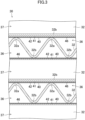
- the moisture permeable membranes (42) of all the partitioning members (40) face the first air flow paths (36) (see FIG. 3 ).
- the spacing members (32) are configured as corrugated plate-shaped members that are formed substantially in a square shape in plan view.
- Each of the spacing members (32) has a plurality of ridges (32a) each having a linear ridge line, and a plurality of valleys (32b) each having a linear bottom line.
- the ridge lines of the ridges (32a) and the bottom lines of the valleys (32b) are substantially parallel to each other.
- Each of the spacing members (32) has the ridges (32a) and the valleys (32b) alternately formed.
- Each of the spacing members (32) keeps the distance between the partitioning members (40) arranged on both sides of the spacing member (32).
- the total heat exchange element (30) adjacent ones of the spacing members (32) with an associated one of the partitioning members (40) interposed therebetween are arranged such that the direction of the ridge lines of one of the spacing members (32) are substantially orthogonal to the direction of the ridge lines of the other spacing member (32).
- This arrangement provides the total heat exchange element (30) with the first air flow paths (36) that open at a pair of opposed side surfaces of the total heat exchange element (30) and the second air flow paths (37) that open at the other pair of opposed side surfaces.
- the total heat exchange element (30) different types of air flow in the first air flow path (36, 121) and the second air flow path (37, 151).
- outdoor air (supply air) to be supplied to an indoor space flows in the first air flow path (36, 121), and room air (exhaust air) discharged to an outdoor space flows in the second air flow path (37, 151).
- the total heat exchange element (30) causes exchange of sensible heat and latent heat (moisture) between the air flowing in the first air flow path (36, 121) and the air flowing in the second air flow path (37, 151).
- the functional material (46) producing the antifungal effect and the antibacterial effect is provided across the entirety of a portion, among the surfaces of each partitioning member (40), which faces the first air flow path (36).
- growth of bacteria and fungi can be reduced almost across the entirety of the portion, of the partitioning member (40) of the total heat exchange element (30), which is in contact with the supply air.
- the supply air passing through the total heat exchange element (30) can thus be kept clean.
- a third embodiment will be described. This embodiment relates to a ventilation device (10) including the total heat exchange element (30) of the second embodiment.
- the ventilation device (10) includes a casing (15) that houses the total heat exchange element (30).
- the casing (15) includes an outdoor air inlet (16), an air supply port (17), an indoor air inlet (18), and an exhaust port (19).
- An air supply passage (21) and an exhaust passage (22) are formed in an internal space of the casing (15).
- the air supply passage (21) has two ends respectively connected to the outdoor air inlet (16) and the air supply port (17).
- the exhaust passage (22) has two ends respectively connected to the indoor air inlet (18) and the exhaust port (19).
- the total heat exchange element (30) is arranged to cross the air supply passage (21) and the exhaust passage (22).
- the total heat exchange element (30) is disposed in the casing (15) such that the first air flow paths (36) communicate with the air supply passage (21) and the second air flow paths (37) communicate with the exhaust passage (22).
- the ventilation device (10) further includes an air supply fan (26) and an exhaust fan (27).
- the air supply fan (26) is arranged downstream of the total heat exchange element (30) in the air supply passage (21) (i.e., near the air supply port (17)).
- the exhaust fan (27) is arranged downstream of the total heat exchange element (30) in the exhaust passage (22) (i.e., near the exhaust port (19)).
- outdoor air flows in the air supply passage (21) toward the indoor space, and outdoor air flows in the exhaust passage (22) toward the outdoor space.
- the total heat exchange element (30) causes exchange of sensible heat and moisture (latent heat) between the room air flowing in the air supply passage (21) and the room air flowing in the exhaust passage (22).
- the ventilation device (10) of this embodiment includes the total heat exchange element (30) of the second embodiment.
- growth of bacteria and fungi can be reduced almost across the entirety of the portion, of the partitioning member (40), in contact with the supply air.
- the supply air to be supplied into the indoor space through the total heat exchange element (30) can be kept clean for a long period of time.
- a fourth embodiment will be described.
- This embodiment relates to a total heat exchange element (30) including the partitioning members (40) of the first embodiment.
- the total heat exchange element (30) of this embodiment is provided for the ventilation device (10) of the third embodiment, and causes exchange of sensible heat and latent heat (moisture) between the supply air and the exhaust air.
- the total heat exchange element (30) is formed in a prism shape having polygonal end faces. Each end face of the total heat exchange element (30) of this embodiment has a horizontally oriented octagonal shape. As also shown in FIG. 6 , the total heat exchange element (30) includes one main heat exchange section (111) and two auxiliary heat exchange sections (112a, 112b).
- the main heat exchange section (111) is located at the middle of the total heat exchange element (30) in the right-to-left direction in FIG. 6 .
- the main heat exchange section (111) is a horizontally oriented rectangular portion.
- the auxiliary heat exchange sections (112a, 112b) are portions of the total heat exchange element (30) and are located on the sides of the main heat exchange section (111) in the right-to-left direction in FIG. 6 .
- the auxiliary heat exchange sections (112a, 112b) are arranged on the respective sides of the main heat exchange section (111) in the right-to-left direction in FIG. 6 .
- each of the auxiliary heat exchange sections (112a, 112b) is a trapezoidal portion.
- the total heat exchange element (30) includes a plurality of first elements (120) and a plurality of second elements (150).
- the first elements (120) and the second elements (150) are alternately stacked in the total heat exchange element (30).
- Each of the first elements (120) forms a first air flow path (121).
- the first air flow path (121) allows the supply air to flow therethrough.
- Each of the second elements (150) forms a second air flow path (151).
- the second air flow path (151) allows the exhaust air to flow therethrough.
- the first air flow paths (121) and the second air flow paths (151) are alternately formed in a stacking direction of the first elements (120) and the second elements (150).
- the total heat exchange element (30) has a first inflow port (122a), a first outflow port (122b), a second inflow port (152a), and a second outflow port (152b), which are formed at side surfaces thereof (surfaces parallel to the stacking direction of the first elements (120) and the second elements (150)).
- the first inflow port (122a) and the first outflow port (122b) are formed at the first element (120) and communicate with the first air flow path (121).
- the second inflow port (152a) and the second outflow port (152b) are formed at the second element (150) and communicate with the second air flow path (151).
- the first inflow port (122a), the first outflow port (122b), the second inflow port (152a), and the second outflow port (152b) are formed at different side surfaces of the total heat exchange element (30).
- the first inflow port (122a) is open at one side surface
- the second outflow port (152b) is open at another side surface.
- the first outflow port (122b) is open at one side surface
- the second inflow port (152a) is open at another side surface.
- the first element (120) includes a first frame (125) and the partitioning member (40) of the first embodiment
- the second element (150) includes a second frame (155) and the partitioning member (40) of the first embodiment.
- Each of the first frame (125) and the second frame (155) is a flat, injection-molded resin member.
- the first frame (125) and the second frame (155) are spacing members that keep a distance between an adjacent pair of the partitioning members (40).
- Each of the first frame (125) and the second frame (155) is formed in a horizontally oriented octagonal shape in plan view (see FIG. 7 ).
- the frame (125, 155) has substantially the same outer shape as those of the end faces of the total heat exchange element (30) in plan view.
- the partitioning member (40) covers substantially the entirety of one surface (the lower surface in FIG. 8 ) of the first frame (125).
- the partitioning member (40) is bonded to the first frame (125) with the moisture permeable membrane (42) facing the first frame (125).
- the moisture permeable membrane (42) of the partitioning member (40) faces the first air flow path (121) formed by the first element (120).
- the partitioning member (40) covers substantially the entirety of one surface (the lower surface in FIG. 8 ) of the second frame (155).
- the partitioning member (40) is bonded to the second frame (155) with the second surface (41b) of the porous base (41) facing the second frame (155).
- the moisture permeable membrane (42) of the partitioning member (40) faces the first air flow path (121) formed by the first element (120) adjacent to the second element (150).
- the outdoor air OA flows into the first inflow port (122a), and the room air RA flows into the second inflow port (152a).
- the outdoor air OA having flowed into the first inflow port (122a) flows in the first air flow path (121) as the supply air, sequentially passes through the auxiliary heat exchange section (112a) (i.e., one of the auxiliary heat exchange sections), the main heat exchange section (111), and the auxiliary heat exchange section (112b) (i.e., the other auxiliary heat exchange section), and is then supplied into the indoor space through the first outflow port (122b).
- the supply air flowing in the first air flow path (121) and the exhaust air flowing in the second air flow path (151) flow in directions intersecting with each other.
- the supply air flowing in the first air flow path (121) and the exhaust air flowing in the second air flow path (151) flow in directions opposite to each other.
- the total heat exchange element (30) causes exchange of sensible heat and latent heat (moisture) between the supply air flowing in the first air flow path (121) and the exhaust air flowing in the second air flow path (151).
- sensible heat and latent heat moisture
- the supply air and the exhaust air in the total heat exchange element (30) one with a higher temperature transfers heat to the other with a lower temperature.
- one with a higher humidity transfers moisture to the other with a lower humidity.
- the total heat exchange element (30) of this embodiment causes exchange of sensible heat and latent heat between the supply air flowing in the first air flow path (121) and the exhaust air flowing in the second air flow path (151), mainly in the main heat exchange section (111).
- the total heat exchange element (30) of this embodiment is a counterflow heat exchanger.
- the functional material (46) producing the antifungal effect and the antibacterial effect is provided across the entirety of a portion, among the surfaces of each partitioning member (40), which faces the first air flow path (121).
- growth of bacteria and fungi can be reduced almost across the entirety of the portion, of the partitioning member (40) of the total heat exchange element (30), which is in contact with the supply air.
- the supply air passing through the total heat exchange element (30) can thus be kept clean.
- the structure of the partitioning member (40) for the total heat exchange element is not limited to the structure of the partitioning member (40) of the first embodiment.
- a partitioning member (40) shown in FIG. 9 includes one porous base (41) and two moisture permeable membranes (42).
- one of the moisture permeable membranes (42) covers a first surface (41a) of the partitioning member (40)
- the other moisture permeable membrane (42) covers a second surface (41b) of the partitioning member (40).
- a partitioning member (40) shown in FIG. 10 part of a moisture permeable membrane (42) enters a porous base (41).
- an aqueous composition for forming the moisture permeable membrane (42) penetrates inside of the porous base (41).
- part of the moisture permeable membrane (42) covers the first surface (41a) of the porous base (41), and the remaining part enters the porous base (41).
- a partitioning member (40) shown in FIG. 11 the entirety of a moisture permeable membrane (42) is included in a porous base (41).
- an aqueous composition for forming the moisture permeable membrane (42) is injected into the porous base (41).
- the moisture permeable membrane (42) is formed at a middle portion of the porous base (41) in a thickness direction thereof.
- a partitioning member (40) shown in FIG. 12 includes two porous bases (41) and one moisture permeable membrane (42).
- the porous bases (41) are provided on the respective sides of the moisture permeable membrane (42) in a thickness direction thereof.
- the moisture permeable membrane (42) of this partitioning member (40) one surface is in contact with a first surface (41a) of one of the porous bases (41), and the other surface is in contact with a second surface (41b) of the other porous base (41).
- the structure of the partitioning member (40) for the total heat exchange element is not limited to the structure of the partitioning member (40) of the first embodiment.
- the partitioning member (40) may include, in addition to the porous base (41) and the moisture permeable membrane (42), a functional membrane (45) containing the functional material (46).
- the moisture permeable membrane (42) of the partitioning member (40) of this variation contains no functional material (46).
- the functional membrane (45) is provided so as to cover the entire surface of the moisture permeable membrane (42).
- the functional membrane (45) is a coating containing the functional material (46).
- the functional membrane (45) has a thickness of 0.5 ⁇ m, for example.
- the functional membrane (45) is thinner than the moisture permeable membrane (42).
- the functional membrane (45) may be provided between the partitioning member (40) and the moisture permeable membrane (42).
- the functional membrane (45) is provided so as to cover the first surface (41a) of the partitioning member (40), and the moisture permeable membrane (42) is provided so as to cover the surface of the functional membrane (45).
- the functional membrane (45) may be provided so as to cover the second surface (41b) of the partitioning member (40).
- the functional membrane (45) covers the surface of the partitioning member (40) on the side opposite to the moisture permeable membrane (42).
- the moisture permeable membranes (42) of all the partitioning members (40) may face the second air flow paths (37, 151).
- FIG. 16 shows an example where this variation is applied to the total heat exchange element (30) of the second embodiment.
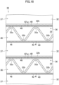
- the second surface (41b) of the porous base (41) of the partitioning member (40) faces the first air flow path (36, 121) in which the supply air flows, and the moisture permeable membrane (42) of the partitioning member (40) faces the second air flow path (37, 151) in which the exhaust air flows.
- the total heat exchange elements (30) of the second and fourth embodiments may have both of the partitioning members (40) including the moisture permeable membranes (42) facing the first air flow paths (36, 121) and the partitioning members (40) including the moisture permeable membranes (42) facing the second air flow paths (37, 151).
- FIG. 17 shows an example where this variation is applied to the total heat exchange element (30) of the second embodiment.
- the partitioning member (40) of each of the above-described embodiments and variations may contain zinc pyrithione (C 10 H 8 N 2 O 2 S 2 Zn) as the functional material (46) producing the antifungal effect and the antibacterial effect.
- Zinc pyrithione as the functional material (46) is dispersed in the form of fine particles in the moisture permeable membrane (42) or the functional membrane (45).
- the particle size (e.g., the major-axis diameter) of the fine particles as the functional material (46) is preferably smaller than the thickness of the moisture permeable membrane (42). If the particle size of the fine particles as the functional material (46) is smaller than the thickness of the moisture permeable membrane (42), the hermeticity of the moisture permeable membrane (42) is kept even in a case where the functional material (46) drops from the moisture permeable membrane (42) for some reason.
- partitioning member (40) of each of the above-described embodiments and variations may contain a quaternary ammonium salt-based antiviral agent (e.g., 3-(triethoxysilyl)propyldimethyloctadecyl ammonium chloride) as the functional material (46) producing an antiviral effect.
- a quaternary ammonium salt-based antiviral agent e.g., 3-(triethoxysilyl)propyldimethyloctadecyl ammonium chloride
- the present disclosure is useful for a partitioning member for a total heat exchange element, a total heat exchange element including the partitioning member, and a ventilation device including the total heat exchange element.
Landscapes
- Engineering & Computer Science (AREA)
- Mechanical Engineering (AREA)
- General Engineering & Computer Science (AREA)
- Physics & Mathematics (AREA)
- Thermal Sciences (AREA)
- Chemical & Material Sciences (AREA)
- Combustion & Propulsion (AREA)
- Heat-Exchange Devices With Radiators And Conduit Assemblies (AREA)
- Separation Using Semi-Permeable Membranes (AREA)
- Air-Conditioning For Vehicles (AREA)
Abstract
Description
- The present disclosure relates to a partitioning member for a total heat exchange element, a total heat exchange element including the partitioning member, and a ventilation device including the total heat exchange element.
- As disclosed in Patent Document 1, a ventilation device including a heat exchange element has been known. The heat exchange element exchanges heat between supply air and exhaust air.
- In the heat exchange element, flat plate-shaped partitioning members and corrugated plate-shaped spacing members are alternately stacked. The partitioning member and the spacing member are bonded to each other with an adhesive. In the heat exchange element of Patent Document 1, growth of bacteria and fungi in the heat exchange element is reduced by use of the adhesive containing an antibacterial/antifungal component.
- Patent Document 1:
Japanese Unexamined Patent Publication No. 2011-163650 - In the heat exchange element of Patent Document 1, the adhesive containing the antibacterial/antifungal component is provided at a portion where the flat plate-shaped partitioning member and the corrugated plate-shaped spacing member contact each other. Thus, growth of bacteria and fungi cannot be reduced at portions of the partitioning member and the spacing member not in contact with the adhesive.
- It is an object of the present disclosure to keep the partitioning member for the total heat exchange element clean.
- A first aspect of the present disclosure is directed to a partitioning member (40) for a total heat exchange element. The partitioning member (40) includes a sheet-shaped porous base (41), a moisture permeable membrane (42) provided on the porous base (41), and a functional material (46) producing at least one of an antifungal effect, an antibacterial effect, or an antiviral effect, the moisture permeable membrane (42) containing the functional material (46).
- In the first aspect, the moisture permeable membrane (42) containing the functional material (46) is provided on the sheet-shaped porous base (41). Thus, the partitioning member (40) for the total heat exchange element can be kept clean.
- A second aspect of the present disclosure is an embodiment of the first aspect. In the second aspect, the functional material (46) is smaller than a thickness of the moisture permeable membrane (42).
- In the second aspect, the functional material (46) smaller than the thickness of the moisture permeable membrane (42) is provided in the moisture permeable membrane (42). Thus, even if the functional material (46) drops from the moisture permeable membrane (42) for some reason, air flowing in a flow path partitioned by the partitioning member (40) for the total heat exchange element does not pass through the moisture permeable membrane (42).
- A third aspect of the present disclosure is directed to a partitioning member (40) for a total heat exchange element. The partitioning member (40) includes a sheet-shaped porous base (41), a moisture permeable membrane (42) provided on the porous base (41), and a functional membrane (45) containing a functional material (46) producing at least one of an antifungal effect, an antibacterial effect, or an antiviral effect and covering a surface of the porous base (41) or the moisture permeable membrane (42).
- In the third aspect, the functional membrane (45) containing the functional material (46) is provided for the partitioning member (40) for the total heat exchange element. Thus, the partitioning member (40) for the total heat exchange element can be kept clean.
- A fourth aspect of the present disclosure is an embodiment of the third aspect. In the fourth aspect, the functional membrane (45) is thinner than the moisture permeable membrane (42).
- In the fourth aspect, the functional membrane (45) is thinner than the moisture permeable membrane (42). Thus, a decrease in the heat exchange amount due to the provision of the functional membrane (45) in the partitioning member (40) for the total heat exchange element is reduced.
- A fifth aspect of the present disclosure is an embodiment of any one of the first to fourth aspects. In the fifth aspect, the moisture permeable membrane (42) is provided so as to cover a surface of the porous base (41), and the surface of the porous base (41) covered with the moisture permeable membrane (42) is subjected to hydrophilic treatment.
- In the fifth aspect, the porous base (41) is subjected to the hydrophilic treatment. Thus, a process of forming the moisture permeable membrane (42) on the surface of the porous base (41) is facilitated.
- A sixth aspect of the present disclosure is an embodiment of any one of the first to fifth aspects. In the sixth aspect, the functional material (46) is a substance containing pyrithione in a molecular structure.
- In the sixth aspect, the substance containing pyrithione in its molecular structure is provided as the functional material (46) in the partitioning member (40) for the total heat exchange element.
- A seventh aspect of the present disclosure is directed to a total heat exchange element (30). The total heat exchange element (30) includes a plurality of partitioning members (40) of any one of the first to sixth aspects, and a spacing member (32, 125, 155) arranged between adjacent ones of the partitioning members (40) stacked, the spacing member (32, 125, 155) keeping a distance between the adjacent partitioning members (40), a first air flow path (36, 121) and a second air flow path (37, 151) being alternately provided with an associated one of the partitioning members (40) interposed therebetween.
- In the seventh aspect, the total heat exchange element (30) includes a plurality of partitioning members (40) of any one of the first to sixth aspects.
- An eighth aspect of the present disclosure is directed to a ventilation device (10). The ventilation device (10) includes the total heat exchange element (30) of the seventh aspect. Supply air to be supplied from an outdoor space to an indoor space flows in the first air flow path (36, 121) of the total heat exchange element (30), and exhaust air to be discharged from the indoor space to the outdoor space flows in the second air flow path (37, 151) of the total heat exchange element (30).
- In the eighth aspect, the ventilation device (10) includes the total heat exchange element (30) of the seventh aspect.
-
-
FIG. 1 is a schematic cross-sectional view of a partitioning member for a total heat exchange element according to a first embodiment. -
FIG. 2 is a schematic perspective view of a total heat exchange element of a second embodiment. -
FIG. 3 is a cross-sectional view of an essential portion of the total heat exchange element of the second embodiment. -
FIG. 4 is a schematic configuration diagram of a ventilation device of a third embodiment. -
FIG. 5 is a perspective view of a total heat exchange element of a fourth embodiment. -
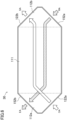
FIG. 6 is a plan view of the total heat exchange element of the fourth embodiment. -
FIG. 7 is a plan view of the total heat exchange element of the fourth embodiment, part of which is extracted. -
FIG. 8 is a perspective view of a cross section taken along line VIII-VIII inFIG. 7 and its periphery. -
FIG. 9 is a schematic cross-sectional view of a partitioning member for a total heat exchange element according to a first variation of another embodiment. -
FIG. 10 is a schematic cross-sectional view of the partitioning member for the total heat exchange element according to the first variation of another embodiment. -
FIG. 11 is a schematic cross-sectional view of the partitioning member for the total heat exchange element according to the first variation of another embodiment. -
FIG. 12 is a schematic cross-sectional view of the partitioning member for the total heat exchange element according to the first variation of another embodiment. -
FIG. 13 is a schematic cross-sectional view of a partitioning member for a total heat exchange element according to a second variation of another embodiment. -
FIG. 14 is a schematic cross-sectional view of the partitioning member for the total heat exchange element according to the second variation of another embodiment. -
FIG. 15 is a schematic cross-sectional view of the partitioning member for the total heat exchange element according to the second variation of another embodiment. -
FIG. 16 is a cross-sectional view of a total heat exchange element of a third variation of another embodiment, which corresponds toFIG. 3 . -
FIG. 17 is a cross-sectional view of a total heat exchange element of a fourth variation of another embodiment, which corresponds toFIG. 3 . - A first embodiment will be described. This embodiment relates to a partitioning member (40) for a total heat exchange element.
- The partitioning member (40) for the total heat exchange element according to this embodiment forms a total heat exchange element (30) provided for a ventilation device (10). The partitioning member (40) for the total heat exchange element according to this embodiment is a member for causing exchange of sensible heat and latent heat (moisture) between supply air and exhaust air. Hereinafter, the "partitioning member for the total heat exchange element" will be simply referred to as a "partitioning member."
- As shown in
FIG. 1 , the partitioning member (40) of this embodiment includes a sheet-shaped porous base (41) and a moisture permeable membrane (42) provided on the porous base (41). In the partitioning member (40) of this embodiment, the moisture permeable membrane (42) is provided to cover a first surface (41a) of the porous base (41), which is one of surfaces of the porous base (41). - The porous base (41) is a porous sheet-shaped member made of polyolefin-based resin, for example. The porous base (41) may be non-woven fabric made of fibrous resin. The porous base (41) has a thickness of 10 µm, for example. Preferably, the porous base (41) is an element that serves as a support for the moisture permeable membrane (42), and has high moisture permeability.
- The first surface (41a), i.e., one of the surfaces of the porous base (41), is subjected to hydrophilic treatment. Examples of the hydrophilic treatment include corona discharge treatment and plasma treatment. The hydrophilic treatment allows generation of a carboxy group, a hydroxy group, or a carbonyl group on the first surface (41a) of the porous base (41).
- The moisture permeable membrane (42) is a coating covering the entirety of the first surface (41a) of the porous base (41). The moisture permeable membrane (42) is made of a polymer having moisture permeability. The polymer forming the moisture permeable membrane (42) is copolymer having a first constitutional unit and a second constitutional unit. The moisture permeable membrane (42) has a thickness of 1 µm, for example. The thickness of the moisture permeable membrane (42) is not particularly limited, and is preferably 0.05 µm to 1 µm and more preferably 0.1 µm to 0.5 µm. In a case where the thickness of the moisture permeable membrane (42) is 0.05 µm or more, favorable film formability is exhibited, leading to improvement in gas barrier properties. In a case where the above-described thickness is 1 µm or less, more favorable moisture permeability is exhibited.
- Examples of monomer forming the first constitutional unit may include 2-methacryloyloxyethyl phosphorylcholine. Examples of monomer forming the second constitutional unit may include (meth)acrylic acid alkyl ester having an alkyl group with a carbon number of 2 or more in an ester moiety, such as (meth)acrylic acid stearyl. In the copolymer forming the moisture permeable membrane (42), the form of copolymer having the first constitutional unit and the second constitutional unit is not particularly limited, and the copolymer forming the moisture permeable membrane (42) may be any of a block copolymer, an alternating copolymer, and a random copolymer.
- The moisture permeable membrane (42) contains a functional material (46) producing an antifungal effect and an antibacterial effect. The moisture permeable membrane (42) of this embodiment contains sodium pyrithione (C5H4NNaOS) as the functional material (46). Molecules of sodium pyrithione, which is the functional material (46), are dispersed in the moisture permeable membrane (42). Thus, the size (the van der Waals radius in this embodiment) of the functional material (46) contained in the moisture permeable membrane (42) is 5 nm or less and less than the thickness (about 1 µm) of the moisture permeable membrane (42).
- A step of forming the moisture permeable membrane (42) on the porous base (41) includes an application step of applying a composition for forming the moisture permeable membrane (42) to the first surface (41a) of the porous base (41) and a drying step of heating a coating formed in the application step and evaporating a solvent. The composition used in the application step is obtained by dissolving or dispersing the above-described copolymer and the functional material (46) in the solvent such as water. The first surface (41a) of the porous base (41), to which surface the composition is applied in the application step, is subjected to the hydrophilic treatment in advance. Thus, the thickness of the coating formed on the first surface (41a) becomes uniform. The moisture permeable membrane (42) with a uniform thickness is formed accordingly.
- Sodium pyrithione which is the functional material (46) of this embodiment is dissolvable in water which is the solvent. Thus, sodium pyrithione which is the functional material (46) is dispersed in the moisture permeable membrane (42) formed by applying the composition to the porous base (41), substantially in the form of molecules.
- In the partitioning member (40) of this embodiment, the moisture permeable membrane (42) covering the entirety of the first surface (41a) of the porous base (41) contains the functional material (46) producing the antifungal effect and the antibacterial effect. Thus, growth of bacteria and fungi can be reduced across the entirety of the partitioning member (40), and the entirety of the partitioning member (40) can be kept clean.
- In the moisture permeable membrane (42) of the partitioning member (40) of this embodiment, sodium pyrithione which is the functional material (46) is distributed substantially uniformly in the form of molecules. Thus, growth of bacteria and fungi can be reduced across the entirety of the partitioning member (40), and the entirety of the partitioning member (40) can be kept clean.
- Sodium pyrithione contained as the functional material (46) in the moisture permeable membrane (42) of this embodiment produces a sufficient antifungal effect and a sufficient antibacterial effect even if the concentration of the sodium pyrithione in the moisture permeable membrane (42) is about 4 ppm.
- For example, in order for "4,4'-(2-ethyl-2-nitropropane-1,3-diyl)bismorpholine" or "silver (Ag)" to produce the sufficient antifungal effect and the sufficient antibacterial effect, the concentration of the substances in the moisture permeable membrane (42) needs to be set to about 500 ppm. From this, it can be understood that sodium pyrithione produces the antifungal effect and the antibacterial effect at a relatively low concentration.
- Thus, according to this embodiment, the concentration of the functional material (46) in the moisture permeable membrane (42) can be reduced to a low concentration, which allows the moisture permeable membrane (42) to contain the functional material (46) producing the antifungal effect and the antibacterial effect without deterioration of the moisture permeability of the moisture permeable membrane (42).
- Further, a substance having pyrithione in its molecular structure, such as sodium pyrithione, has a property of not causing deterioration of the copolymer forming the moisture permeable membrane (42). Thus, according to this embodiment, sodium pyrithione is used as the functional material (46), thereby making it possible to cause the moisture permeable membrane (42) to contain the functional material (46) producing the antifungal effect and the antibacterial effect without deterioration of durability of the moisture permeable membrane (42).
- Here, in a case where the functional material (46) is contained in the form of particles (solid) in the moisture permeable membrane (42), the functional material (46) may drop from the moisture permeable membrane (42). If the functional material (46) drops from the moisture permeable membrane (42), a void is formed at a portion where the functional material (46) is used to be present. For this reason, if the functional material (46) whose particle size is greater than the thickness of the moisture permeable membrane (42) drops from the moisture permeable membrane (42), voids penetrating the moisture permeable membrane (42) in the thickness direction are formed in the moisture permeable membrane (42). If such voids are formed in the moisture permeable membrane (42), air flowing on both sides of the partitioning member (40) is mixed through the voids in the moisture permeable membrane (42), resulting in a deterioration of the hermeticity of the partitioning member (40).
- On the other hand, in the moisture permeable membrane (42) of the partitioning member (40) of this embodiment, sodium pyrithione which is the functional material (46) is present in the form of molecules in the moisture permeable membrane (42). Thus, the functional material (46) will not drop from the moisture permeable membrane (42) of this embodiment. Consequently, according to this embodiment, the hermeticity of the partitioning member (40) can be kept for a relatively long period of time.
- A second embodiment will be described. This embodiment relates to a total heat exchange element (30) including the partitioning members (40) of the first embodiment.
- As shown in
FIGS. 2 and3 , the total heat exchange element (30) is a cross-flow heat exchanger having a plurality of first air flow paths (36) and a plurality of second air flow paths (37). The total heat exchange element (30) includes the plurality of partitioning members (40) and a plurality of spacing members (32). The total heat exchange element (30) has a quadrangular prism-like shape as a whole. - In the total heat exchange element (30), the partitioning members (40) and the spacing members (32) are stacked alternately. In the total heat exchange element (30), a distance between each adjacent pair of the partitioning members (40) is kept substantially constant by an associated one of the spacing members (32).
- In the total heat exchange element (30), the first air flow paths (36) and the second air flow paths (37) are alternately formed in a stacking direction of the partitioning members (40) and the spacing members (32). Each of the partitioning members (40) separates an adjacent pair of the first air flow path (36) and the second air flow path (37) from each other.
- The partitioning member (40) forming the total heat exchange element (30) of this embodiment is formed substantially in a square shape in plan view. In the total heat exchange element (30) of this embodiment, the moisture permeable membranes (42) of all the partitioning members (40) face the first air flow paths (36) (see
FIG. 3 ). - The spacing members (32) are configured as corrugated plate-shaped members that are formed substantially in a square shape in plan view. Each of the spacing members (32) has a plurality of ridges (32a) each having a linear ridge line, and a plurality of valleys (32b) each having a linear bottom line. The ridge lines of the ridges (32a) and the bottom lines of the valleys (32b) are substantially parallel to each other. Each of the spacing members (32) has the ridges (32a) and the valleys (32b) alternately formed. Each of the spacing members (32) keeps the distance between the partitioning members (40) arranged on both sides of the spacing member (32).
- In the total heat exchange element (30), adjacent ones of the spacing members (32) with an associated one of the partitioning members (40) interposed therebetween are arranged such that the direction of the ridge lines of one of the spacing members (32) are substantially orthogonal to the direction of the ridge lines of the other spacing member (32). This arrangement provides the total heat exchange element (30) with the first air flow paths (36) that open at a pair of opposed side surfaces of the total heat exchange element (30) and the second air flow paths (37) that open at the other pair of opposed side surfaces.
- In the total heat exchange element (30), different types of air flow in the first air flow path (36, 121) and the second air flow path (37, 151). For example, in the total heat exchange element (30) provided for a ventilation device, outdoor air (supply air) to be supplied to an indoor space flows in the first air flow path (36, 121), and room air (exhaust air) discharged to an outdoor space flows in the second air flow path (37, 151). The total heat exchange element (30) causes exchange of sensible heat and latent heat (moisture) between the air flowing in the first air flow path (36, 121) and the air flowing in the second air flow path (37, 151).
- In the total heat exchange element (30) of this embodiment, the functional material (46) producing the antifungal effect and the antibacterial effect is provided across the entirety of a portion, among the surfaces of each partitioning member (40), which faces the first air flow path (36). Thus, growth of bacteria and fungi can be reduced almost across the entirety of the portion, of the partitioning member (40) of the total heat exchange element (30), which is in contact with the supply air. The supply air passing through the total heat exchange element (30) can thus be kept clean.
- A third embodiment will be described. This embodiment relates to a ventilation device (10) including the total heat exchange element (30) of the second embodiment.
- As shown in
FIG. 4 , the ventilation device (10) includes a casing (15) that houses the total heat exchange element (30). The casing (15) includes an outdoor air inlet (16), an air supply port (17), an indoor air inlet (18), and an exhaust port (19). An air supply passage (21) and an exhaust passage (22) are formed in an internal space of the casing (15). The air supply passage (21) has two ends respectively connected to the outdoor air inlet (16) and the air supply port (17). The exhaust passage (22) has two ends respectively connected to the indoor air inlet (18) and the exhaust port (19). - The total heat exchange element (30) is arranged to cross the air supply passage (21) and the exhaust passage (22). The total heat exchange element (30) is disposed in the casing (15) such that the first air flow paths (36) communicate with the air supply passage (21) and the second air flow paths (37) communicate with the exhaust passage (22).
- The ventilation device (10) further includes an air supply fan (26) and an exhaust fan (27). The air supply fan (26) is arranged downstream of the total heat exchange element (30) in the air supply passage (21) (i.e., near the air supply port (17)). The exhaust fan (27) is arranged downstream of the total heat exchange element (30) in the exhaust passage (22) (i.e., near the exhaust port (19)).
- In the ventilation device (10), outdoor air flows in the air supply passage (21) toward the indoor space, and outdoor air flows in the exhaust passage (22) toward the outdoor space. The total heat exchange element (30) causes exchange of sensible heat and moisture (latent heat) between the room air flowing in the air supply passage (21) and the room air flowing in the exhaust passage (22).
- The ventilation device (10) of this embodiment includes the total heat exchange element (30) of the second embodiment. In the total heat exchange element (30) of the second embodiment, growth of bacteria and fungi can be reduced almost across the entirety of the portion, of the partitioning member (40), in contact with the supply air. Thus, according to this embodiment, the supply air to be supplied into the indoor space through the total heat exchange element (30) can be kept clean for a long period of time.
- A fourth embodiment will be described. This embodiment relates to a total heat exchange element (30) including the partitioning members (40) of the first embodiment. Similarly to the total heat exchange element (30) of the second embodiment, the total heat exchange element (30) of this embodiment is provided for the ventilation device (10) of the third embodiment, and causes exchange of sensible heat and latent heat (moisture) between the supply air and the exhaust air.
- As shown in
FIG. 5 , the total heat exchange element (30) is formed in a prism shape having polygonal end faces. Each end face of the total heat exchange element (30) of this embodiment has a horizontally oriented octagonal shape. As also shown inFIG. 6 , the total heat exchange element (30) includes one main heat exchange section (111) and two auxiliary heat exchange sections (112a, 112b). - The main heat exchange section (111) is located at the middle of the total heat exchange element (30) in the right-to-left direction in
FIG. 6 . When the total heat exchange element (30) is viewed in plan as shown inFIG. 6 , the main heat exchange section (111) is a horizontally oriented rectangular portion. The auxiliary heat exchange sections (112a, 112b) are portions of the total heat exchange element (30) and are located on the sides of the main heat exchange section (111) in the right-to-left direction inFIG. 6 . In the total heat exchange element (30), the auxiliary heat exchange sections (112a, 112b) are arranged on the respective sides of the main heat exchange section (111) in the right-to-left direction inFIG. 6 . In the plan view of the total heat exchange element (30) as shown inFIG. 6 , each of the auxiliary heat exchange sections (112a, 112b) is a trapezoidal portion. - The total heat exchange element (30) includes a plurality of first elements (120) and a plurality of second elements (150). The first elements (120) and the second elements (150) are alternately stacked in the total heat exchange element (30). Each of the first elements (120) forms a first air flow path (121). The first air flow path (121) allows the supply air to flow therethrough. Each of the second elements (150) forms a second air flow path (151). The second air flow path (151) allows the exhaust air to flow therethrough. In the total heat exchange element (30), the first air flow paths (121) and the second air flow paths (151) are alternately formed in a stacking direction of the first elements (120) and the second elements (150).
- The total heat exchange element (30) has a first inflow port (122a), a first outflow port (122b), a second inflow port (152a), and a second outflow port (152b), which are formed at side surfaces thereof (surfaces parallel to the stacking direction of the first elements (120) and the second elements (150)). The first inflow port (122a) and the first outflow port (122b) are formed at the first element (120) and communicate with the first air flow path (121). The second inflow port (152a) and the second outflow port (152b) are formed at the second element (150) and communicate with the second air flow path (151).
- As also shown in
FIGS. 6 and7 , the first inflow port (122a), the first outflow port (122b), the second inflow port (152a), and the second outflow port (152b) are formed at different side surfaces of the total heat exchange element (30). In the auxiliary heat exchange section (112a), which is one of auxiliary heat exchange sections of the total heat exchange element (30), the first inflow port (122a) is open at one side surface, and the second outflow port (152b) is open at another side surface. In the auxiliary heat exchange section (112b), which is the other auxiliary heat exchange section of the total heat exchange element (30), the first outflow port (122b) is open at one side surface, and the second inflow port (152a) is open at another side surface. - As shown in
FIG. 8 , the first element (120) includes a first frame (125) and the partitioning member (40) of the first embodiment, and the second element (150) includes a second frame (155) and the partitioning member (40) of the first embodiment. - Each of the first frame (125) and the second frame (155) is a flat, injection-molded resin member. The first frame (125) and the second frame (155) are spacing members that keep a distance between an adjacent pair of the partitioning members (40). Each of the first frame (125) and the second frame (155) is formed in a horizontally oriented octagonal shape in plan view (see
FIG. 7 ). The frame (125, 155) has substantially the same outer shape as those of the end faces of the total heat exchange element (30) in plan view. - In the first element (120), the partitioning member (40) covers substantially the entirety of one surface (the lower surface in
FIG. 8 ) of the first frame (125). In the first element (120), the partitioning member (40) is bonded to the first frame (125) with the moisture permeable membrane (42) facing the first frame (125). In the first element (120), the moisture permeable membrane (42) of the partitioning member (40) faces the first air flow path (121) formed by the first element (120). - In the second element (150), the partitioning member (40) covers substantially the entirety of one surface (the lower surface in
FIG. 8 ) of the second frame (155). In the second element (150), the partitioning member (40) is bonded to the second frame (155) with the second surface (41b) of the porous base (41) facing the second frame (155). In the second element (150), the moisture permeable membrane (42) of the partitioning member (40) faces the first air flow path (121) formed by the first element (120) adjacent to the second element (150). - In the total heat exchange element (30), as shown in
FIG. 6 , the outdoor air OA flows into the first inflow port (122a), and the room air RA flows into the second inflow port (152a). The outdoor air OA having flowed into the first inflow port (122a) flows in the first air flow path (121) as the supply air, sequentially passes through the auxiliary heat exchange section (112a) (i.e., one of the auxiliary heat exchange sections), the main heat exchange section (111), and the auxiliary heat exchange section (112b) (i.e., the other auxiliary heat exchange section), and is then supplied into the indoor space through the first outflow port (122b). The room air RA having flowed into the second inflow port (152a) flows in the second air flow path (151) as the exhaust air, sequentially passes through the auxiliary heat exchange section (112b) (i.e., the other auxiliary heat exchange section), the main heat exchange section (111), and the auxiliary heat exchange section (112a) (i.e., one of the auxiliary heat exchange section), and is then discharged to the outdoor space through the second outflow port (152b). - In each of the auxiliary heat exchange sections (112a, 112b) of the total heat exchange element (30), the supply air flowing in the first air flow path (121) and the exhaust air flowing in the second air flow path (151) flow in directions intersecting with each other. In the main heat exchange section (111) of the total heat exchange element (30), the supply air flowing in the first air flow path (121) and the exhaust air flowing in the second air flow path (151) flow in directions opposite to each other.
- The total heat exchange element (30) causes exchange of sensible heat and latent heat (moisture) between the supply air flowing in the first air flow path (121) and the exhaust air flowing in the second air flow path (151). Of the supply air and the exhaust air in the total heat exchange element (30), one with a higher temperature transfers heat to the other with a lower temperature. Further, of the supply air and the exhaust air in the total heat exchange element (30), one with a higher humidity transfers moisture to the other with a lower humidity.
- The total heat exchange element (30) of this embodiment causes exchange of sensible heat and latent heat between the supply air flowing in the first air flow path (121) and the exhaust air flowing in the second air flow path (151), mainly in the main heat exchange section (111). Thus, the total heat exchange element (30) of this embodiment is a counterflow heat exchanger.
- In the total heat exchange element (30) of this embodiment, the functional material (46) producing the antifungal effect and the antibacterial effect is provided across the entirety of a portion, among the surfaces of each partitioning member (40), which faces the first air flow path (121). Thus, growth of bacteria and fungi can be reduced almost across the entirety of the portion, of the partitioning member (40) of the total heat exchange element (30), which is in contact with the supply air. The supply air passing through the total heat exchange element (30) can thus be kept clean.
- The structure of the partitioning member (40) for the total heat exchange element is not limited to the structure of the partitioning member (40) of the first embodiment.
- For example, a partitioning member (40) shown in
FIG. 9 includes one porous base (41) and two moisture permeable membranes (42). In this partitioning member (40), one of the moisture permeable membranes (42) covers a first surface (41a) of the partitioning member (40), and the other moisture permeable membrane (42) covers a second surface (41b) of the partitioning member (40). - In a partitioning member (40) shown in
FIG. 10 , part of a moisture permeable membrane (42) enters a porous base (41). In manufacturing this partitioning member (40), an aqueous composition for forming the moisture permeable membrane (42) penetrates inside of the porous base (41). Thus, in this partitioning member (40), part of the moisture permeable membrane (42) covers the first surface (41a) of the porous base (41), and the remaining part enters the porous base (41). - In a partitioning member (40) shown in
FIG. 11 , the entirety of a moisture permeable membrane (42) is included in a porous base (41). In manufacturing this partitioning member (40), an aqueous composition for forming the moisture permeable membrane (42) is injected into the porous base (41). In this partitioning member (40), the moisture permeable membrane (42) is formed at a middle portion of the porous base (41) in a thickness direction thereof. - A partitioning member (40) shown in
FIG. 12 includes two porous bases (41) and one moisture permeable membrane (42). In this partitioning member (40), the porous bases (41) are provided on the respective sides of the moisture permeable membrane (42) in a thickness direction thereof. Of the moisture permeable membrane (42) of this partitioning member (40), one surface is in contact with a first surface (41a) of one of the porous bases (41), and the other surface is in contact with a second surface (41b) of the other porous base (41). - The structure of the partitioning member (40) for the total heat exchange element is not limited to the structure of the partitioning member (40) of the first embodiment.
- The partitioning member (40) may include, in addition to the porous base (41) and the moisture permeable membrane (42), a functional membrane (45) containing the functional material (46). The moisture permeable membrane (42) of the partitioning member (40) of this variation contains no functional material (46). Here, an example where this variation is applied to the partitioning member (40) of the first embodiment will be described.
- In the partitioning member (40) of this variation shown in
FIG. 13 , the functional membrane (45) is provided so as to cover the entire surface of the moisture permeable membrane (42). The functional membrane (45) is a coating containing the functional material (46). The functional membrane (45) has a thickness of 0.5 µm, for example. The functional membrane (45) is thinner than the moisture permeable membrane (42). - As shown in
FIG. 14 , the functional membrane (45) may be provided between the partitioning member (40) and the moisture permeable membrane (42). In this case, the functional membrane (45) is provided so as to cover the first surface (41a) of the partitioning member (40), and the moisture permeable membrane (42) is provided so as to cover the surface of the functional membrane (45). - As shown in
FIG. 15 , the functional membrane (45) may be provided so as to cover the second surface (41b) of the partitioning member (40). In this case, the functional membrane (45) covers the surface of the partitioning member (40) on the side opposite to the moisture permeable membrane (42). - As shown in
FIG. 16 , in the total heat exchange elements (30) of the second and fourth embodiments, the moisture permeable membranes (42) of all the partitioning members (40) may face the second air flow paths (37, 151).FIG. 16 shows an example where this variation is applied to the total heat exchange element (30) of the second embodiment. - In the total heat exchange element (30) of this variation, the second surface (41b) of the porous base (41) of the partitioning member (40) faces the first air flow path (36, 121) in which the supply air flows, and the moisture permeable membrane (42) of the partitioning member (40) faces the second air flow path (37, 151) in which the exhaust air flows.
- The total heat exchange elements (30) of the second and fourth embodiments may have both of the partitioning members (40) including the moisture permeable membranes (42) facing the first air flow paths (36, 121) and the partitioning members (40) including the moisture permeable membranes (42) facing the second air flow paths (37, 151).
- For example, in a total heat exchange element (30) shown in
FIG. 17 , the partitioning members (40) including the moisture permeable membranes (42) facing the first air flow paths (36, 121) and the partitioning members (40) including the moisture permeable membranes (42) facing the second air flow paths (37, 151) are alternately arranged in the stacking direction of the partitioning members (40) and the spacing members (32, 125, 155).FIG. 17 shows an example where this variation is applied to the total heat exchange element (30) of the second embodiment. - The partitioning member (40) of each of the above-described embodiments and variations may contain zinc pyrithione (C10H8N2O2S2Zn) as the functional material (46) producing the antifungal effect and the antibacterial effect. Zinc pyrithione as the functional material (46) is dispersed in the form of fine particles in the moisture permeable membrane (42) or the functional membrane (45).
- In a case where the functional material (46) is contained in the form of fine particles in the moisture permeable membrane (42), the particle size (e.g., the major-axis diameter) of the fine particles as the functional material (46) is preferably smaller than the thickness of the moisture permeable membrane (42). If the particle size of the fine particles as the functional material (46) is smaller than the thickness of the moisture permeable membrane (42), the hermeticity of the moisture permeable membrane (42) is kept even in a case where the functional material (46) drops from the moisture permeable membrane (42) for some reason.
- Further, the partitioning member (40) of each of the above-described embodiments and variations may contain a quaternary ammonium salt-based antiviral agent (e.g., 3-(triethoxysilyl)propyldimethyloctadecyl ammonium chloride) as the functional material (46) producing an antiviral effect.
- While the embodiments and the variations thereof have been described above, it will be understood that various changes in form and details may be made without departing from the spirit and scope of the claims. The above-described embodiments and variations may be combined and replaced with each other without deteriorating intended functions of the present disclosure. The ordinal numbers such as "first," "second," "third," ..., in the description and claims are used to distinguish the terms to which these expressions are given, and do not limit the number and order of the terms.
- As described above, the present disclosure is useful for a partitioning member for a total heat exchange element, a total heat exchange element including the partitioning member, and a ventilation device including the total heat exchange element.
-
- 10
- Ventilation Device
- 32
- Spacing Member
- 36
- First Air Flow Path
- 37
- Second Air Flow Path
- 40
- Partitioning Member for Total Heat Exchange Element
- 41
- Porous Base
- 41a
- First Surface (of Porous Base)
- 42
- Moisture Permeable Membrane
- 45
- Functional Membrane
- 46
- Functional Material
- 121
- First Air Flow Path
- 125
- First Frame (Spacing Member)
- 151
- Second Air Flow Path
- 155
- Second Frame (Spacing Member)
Claims (8)
- A partitioning member for a total heat exchange element, comprising:a sheet-shaped porous base (41);a moisture permeable membrane (42) provided on the porous base (41); anda functional material (46) producing at least one of an antifungal effect, an antibacterial effect, or an antiviral effect,the moisture permeable membrane (42) containing the functional material (46).
- The partitioning member of claim 1, wherein
the functional material (46) is smaller than a thickness of the moisture permeable membrane (42). - A partitioning member for a total heat exchange element, comprising:a sheet-shaped porous base (41);a moisture permeable membrane (42) provided on the porous base (41); anda functional membrane (45) containing a functional material (46) producing at least one of an antifungal effect, an antibacterial effect, or an antiviral effect and covering a surface of the porous base (41) or the moisture permeable membrane (42).
- The partitioning member of claim 3, wherein
the functional membrane (45) is thinner than the moisture permeable membrane (42). - The partitioning member of any one of claims 1 to 4, whereinthe moisture permeable membrane (42) is provided so as to cover a surface of the porous base (41), andthe surface of the porous base (41) covered with the moisture permeable membrane (42) is subjected to hydrophilic treatment.
- The partitioning member of any one of claims 1 to 5, wherein
the functional material (46) is a substance containing pyrithione in a molecular structure. - A total heat exchange element comprising:a plurality of partitioning members (40) of any one of claims 1 to 6; anda spacing member (32, 125, 155) arranged between adjacent ones of the partitioning members (40) stacked, the spacing member (32, 125, 155) keeping a distance between the adjacent partitioning members (40),a first air flow path (36, 121) and a second air flow path (37, 151) being alternately provided with an associated one of the partitioning members (40) interposed therebetween.
- A ventilation device comprising:the total heat exchange element (30) of claim 7,supply air to be supplied from an outdoor space to an indoor space flowing in the first air flow path (36, 121) of the total heat exchange element (30), and exhaust air to be discharged from the indoor space to the outdoor space flowing in the second air flow path (37, 151) of the total heat exchange element (30).
Applications Claiming Priority (2)
| Application Number | Priority Date | Filing Date | Title |
|---|---|---|---|
| JP2020164299A JP7142066B2 (en) | 2020-09-30 | 2020-09-30 | Partition member for total heat exchange element, total heat exchange element, and ventilator |
| PCT/JP2021/035225 WO2022071166A1 (en) | 2020-09-30 | 2021-09-27 | Partitioning member for total heat exchange elements, total heat exchange element, and ventilation apparatus |
Publications (3)
| Publication Number | Publication Date |
|---|---|
| EP4191187A1 true EP4191187A1 (en) | 2023-06-07 |
| EP4191187A4 EP4191187A4 (en) | 2024-09-11 |
| EP4191187B1 EP4191187B1 (en) | 2026-04-22 |
Family
ID=80951474
Family Applications (1)
| Application Number | Title | Priority Date | Filing Date |
|---|---|---|---|
| EP21875468.7A Active EP4191187B1 (en) | 2020-09-30 | 2021-09-27 | Partitioning member for total heat exchange elements, total heat exchange element, and ventilation apparatus |
Country Status (7)
| Country | Link |
|---|---|
| US (1) | US20230204307A1 (en) |
| EP (1) | EP4191187B1 (en) |
| JP (1) | JP7142066B2 (en) |
| CN (1) | CN116648592A (en) |
| AU (1) | AU2021351332B2 (en) |
| CA (1) | CA3191091A1 (en) |
| WO (1) | WO2022071166A1 (en) |
Families Citing this family (3)
| Publication number | Priority date | Publication date | Assignee | Title |
|---|---|---|---|---|
| EP4501502A4 (en) | 2022-03-30 | 2026-02-18 | Mitsubishi Materials Corp | Surface-coated cutting tool |
| NL2034333B1 (en) * | 2023-03-13 | 2024-09-24 | Brink Climate Systems B V | Process for manufacture of heat exchanger |
| CN121452861A (en) * | 2024-08-02 | 2026-02-03 | 大金工业株式会社 | Heat exchange element, total heat exchange core assembly and air treatment equipment |
Family Cites Families (24)
| Publication number | Priority date | Publication date | Assignee | Title |
|---|---|---|---|---|
| JP4206894B2 (en) * | 2003-10-15 | 2009-01-14 | 三菱電機株式会社 | Total heat exchange element |
| JP4980789B2 (en) * | 2006-06-05 | 2012-07-18 | レンゴー株式会社 | Total heat exchanger seat |
| JP2008224204A (en) * | 2007-02-16 | 2008-09-25 | Kobe Steel Ltd | Aluminum fin material for heat exchanger |
| JP2009235338A (en) * | 2008-03-28 | 2009-10-15 | Mitsubishi Electric Corp | Coating composition, heat exchanger, air conditioner |
| LT2435171T (en) * | 2009-05-18 | 2021-09-27 | Zehnder Group International Ag | Coated membranes for enthalpy exchange and other applications |
| PL2500681T3 (en) * | 2009-11-11 | 2018-12-31 | Mitsubishi Electric Corporation | Total heat exchanger and method for producing partition plate used in same |
| JP2011163650A (en) | 2010-02-09 | 2011-08-25 | Mitsubishi Electric Corp | Heat exchange element, method of manufacturing the heat exchange element and heat exchange ventilation device |
| US9429366B2 (en) * | 2010-09-29 | 2016-08-30 | Kraton Polymers U.S. Llc | Energy recovery ventilation sulfonated block copolymer laminate membrane |
| EP2767769B1 (en) * | 2011-09-16 | 2019-07-17 | Daikin Industries, Ltd. | Humidity control module, and humidity control device |
| CN202463073U (en) * | 2011-10-25 | 2012-10-03 | 宁波东大空调设备有限公司 | Heterogenous film and heterogenous film core |
| JP5816821B2 (en) * | 2012-09-11 | 2015-11-18 | パナソニックIpマネジメント株式会社 | Total heat exchange element partition member and total heat exchange element and heat exchange type ventilator using the total heat exchange element partition member |
| CA2917792C (en) * | 2013-07-19 | 2018-03-20 | Asahi Kasei Fibers Corporation | Fine cellulose fiber sheet |
| JP6364618B2 (en) * | 2013-09-17 | 2018-08-01 | パナソニックIpマネジメント株式会社 | Partition member for total heat exchange element, total heat exchange element and total heat exchange type ventilator using the same |
| US20160252269A1 (en) * | 2013-10-02 | 2016-09-01 | Toray Industries, Inc. | Heat exchange element and heat exchanger |
| JP6528687B2 (en) * | 2014-01-27 | 2019-06-12 | 日本エクスラン工業株式会社 | Hygroscopic polymer particles, and sheets, elements and total heat exchangers comprising the particles |
| JP6443246B2 (en) * | 2014-07-15 | 2018-12-26 | 王子ホールディングス株式会社 | Base paper for total heat exchanger element and manufacturing method thereof |
| KR20160123876A (en) * | 2015-04-17 | 2016-10-26 | 주식회사 한누리공조 | Sensible heat exchange device |
| JP2017179613A (en) * | 2016-03-28 | 2017-10-05 | 王子ホールディングス株式会社 | Moisture permeable sheet, manufacturing method thereof, base paper for total heat exchanger element, and total heat exchanger element |
| WO2018131719A1 (en) * | 2017-01-16 | 2018-07-19 | 国立大学法人北海道大学 | Sheet for total heat exchange element and method for producing sheet for total heat exchange element |
| JP2019011535A (en) * | 2017-06-30 | 2019-01-24 | 旭化成株式会社 | Porous sheet and porous laminated sheet |
| JP6636217B2 (en) * | 2017-11-16 | 2020-01-29 | 三菱電機株式会社 | Total heat exchange element and total heat exchanger |
| JP6633263B1 (en) * | 2019-03-25 | 2020-01-22 | 三菱電機株式会社 | Partition plate for total heat exchange element, total heat exchange element and total heat exchanger using the same, and method of manufacturing partition plate for total heat exchange element |
| EP4019883B1 (en) * | 2019-08-20 | 2025-04-02 | Toray Industries, Inc. | Sheet for heat exchange element |
| CN111697185B (en) * | 2020-06-22 | 2023-07-18 | 欣旺达电动汽车电池有限公司 | Modification method of porous base film, modified porous base film and application |
-
2020
- 2020-09-30 JP JP2020164299A patent/JP7142066B2/en active Active
-
2021
- 2021-09-27 AU AU2021351332A patent/AU2021351332B2/en active Active
- 2021-09-27 CN CN202180062636.7A patent/CN116648592A/en active Pending
- 2021-09-27 WO PCT/JP2021/035225 patent/WO2022071166A1/en not_active Ceased
- 2021-09-27 EP EP21875468.7A patent/EP4191187B1/en active Active
- 2021-09-27 CA CA3191091A patent/CA3191091A1/en active Pending
-
2023
- 2023-02-28 US US18/115,601 patent/US20230204307A1/en active Pending
Also Published As
| Publication number | Publication date |
|---|---|
| AU2021351332A1 (en) | 2023-05-11 |
| US20230204307A1 (en) | 2023-06-29 |
| EP4191187A4 (en) | 2024-09-11 |
| AU2021351332B2 (en) | 2024-05-09 |
| CN116648592A (en) | 2023-08-25 |
| AU2021351332A9 (en) | 2025-03-13 |
| EP4191187B1 (en) | 2026-04-22 |
| JP7142066B2 (en) | 2022-09-26 |
| CA3191091A1 (en) | 2022-04-07 |
| JP2022056507A (en) | 2022-04-11 |
| WO2022071166A1 (en) | 2022-04-07 |
Similar Documents
| Publication | Publication Date | Title |
|---|---|---|
| US20230204307A1 (en) | Partitioning member for total heat exchange elements, total heat exchange element, and ventilation apparatus | |
| JP6790321B2 (en) | Humidifier fluid plate | |
| KR20140137433A (en) | Heat-exchange element and air conditioner | |
| CN101266109A (en) | Total heat exchanger and manufacturing method thereof | |
| JPH0211837B2 (en) | ||
| EP3954961B1 (en) | Total heat exchange element | |
| US20250085004A1 (en) | Heat exchanging element and heat exchange ventilator | |
| EP3805685B1 (en) | Total heat exchange element and method for manufacturing same | |
| JP3045146B2 (en) | Dehumidifier | |
| JP5191877B2 (en) | Total heat exchanger | |
| CN104321611B (en) | Laminated total heat exchange element and heat exchange ventilation device | |
| JPS60205193A (en) | All weather heat exchanger | |
| JP3461697B2 (en) | Heat exchange element | |
| EP3954962A1 (en) | Method for using sheet-shaped member | |
| JP2006071150A (en) | Heat exchange element | |
| JP2000042344A (en) | Dehumidifier | |
| WO2025141820A1 (en) | Heat exchange element | |
| JP7126617B2 (en) | Heat exchange element and heat exchange ventilator | |
| WO2024053082A1 (en) | Heat exchange element and heat exchange ventilation device | |
| WO2026028174A1 (en) | Heat exchange element, total heat exchange core assembly, and air handling device | |
| JPH05157470A (en) | Heat exchanger |
Legal Events
| Date | Code | Title | Description |
|---|---|---|---|
| STAA | Information on the status of an ep patent application or granted ep patent |
Free format text: STATUS: THE INTERNATIONAL PUBLICATION HAS BEEN MADE |
|
| PUAI | Public reference made under article 153(3) epc to a published international application that has entered the european phase |
Free format text: ORIGINAL CODE: 0009012 |
|
| STAA | Information on the status of an ep patent application or granted ep patent |
Free format text: STATUS: REQUEST FOR EXAMINATION WAS MADE |
|
| 17P | Request for examination filed |
Effective date: 20230302 |
|
| AK | Designated contracting states |
Kind code of ref document: A1 Designated state(s): AL AT BE BG CH CY CZ DE DK EE ES FI FR GB GR HR HU IE IS IT LI LT LU LV MC MK MT NL NO PL PT RO RS SE SI SK SM TR |
|
| DAV | Request for validation of the european patent (deleted) | ||
| DAX | Request for extension of the european patent (deleted) | ||
| A4 | Supplementary search report drawn up and despatched |
Effective date: 20240808 |
|
| RIC1 | Information provided on ipc code assigned before grant |
Ipc: F24F 7/08 20060101ALI20240802BHEP Ipc: F28F 21/00 20060101ALI20240802BHEP Ipc: F28F 13/18 20060101ALI20240802BHEP Ipc: F28F 3/08 20060101ALI20240802BHEP Ipc: F28F 3/00 20060101ALI20240802BHEP Ipc: F28D 9/00 20060101AFI20240802BHEP |
|
| GRAP | Despatch of communication of intention to grant a patent |
Free format text: ORIGINAL CODE: EPIDOSNIGR1 |
|
| STAA | Information on the status of an ep patent application or granted ep patent |
Free format text: STATUS: GRANT OF PATENT IS INTENDED |
|
| INTG | Intention to grant announced |
Effective date: 20251219 |
|
| GRAS | Grant fee paid |
Free format text: ORIGINAL CODE: EPIDOSNIGR3 |
|
| GRAA | (expected) grant |
Free format text: ORIGINAL CODE: 0009210 |
|
| STAA | Information on the status of an ep patent application or granted ep patent |
Free format text: STATUS: THE PATENT HAS BEEN GRANTED |
|
| AK | Designated contracting states |
Kind code of ref document: B1 Designated state(s): AL AT BE BG CH CY CZ DE DK EE ES FI FR GB GR HR HU IE IS IT LI LT LU LV MC MK MT NL NO PL PT RO RS SE SI SK SM TR |
|
| REG | Reference to a national code |
Ref country code: CH Ref legal event code: F10 Free format text: ST27 STATUS EVENT CODE: U-0-0-F10-F00 (AS PROVIDED BY THE NATIONAL OFFICE) Effective date: 20260422 Ref country code: GB Ref legal event code: FG4D |