EP4191156A1 - Air diffusion apparatus and floor-mounted air conditioner - Google Patents
Air diffusion apparatus and floor-mounted air conditioner Download PDFInfo
- Publication number
- EP4191156A1 EP4191156A1 EP21870774.3A EP21870774A EP4191156A1 EP 4191156 A1 EP4191156 A1 EP 4191156A1 EP 21870774 A EP21870774 A EP 21870774A EP 4191156 A1 EP4191156 A1 EP 4191156A1
- Authority
- EP
- European Patent Office
- Prior art keywords
- air dispersing
- air
- plate
- dispersing plate
- impeller
- Prior art date
- Legal status (The legal status is an assumption and is not a legal conclusion. Google has not performed a legal analysis and makes no representation as to the accuracy of the status listed.)
- Pending
Links
Images







Classifications
-
- F—MECHANICAL ENGINEERING; LIGHTING; HEATING; WEAPONS; BLASTING
- F24—HEATING; RANGES; VENTILATING
- F24F—AIR-CONDITIONING; AIR-HUMIDIFICATION; VENTILATION; USE OF AIR CURRENTS FOR SCREENING
- F24F1/00—Room units for air-conditioning, e.g. separate or self-contained units or units receiving primary air from a central station
- F24F1/0007—Indoor units, e.g. fan coil units
- F24F1/0011—Indoor units, e.g. fan coil units characterised by air outlets
- F24F1/0014—Indoor units, e.g. fan coil units characterised by air outlets having two or more outlet openings
-
- F—MECHANICAL ENGINEERING; LIGHTING; HEATING; WEAPONS; BLASTING
- F24—HEATING; RANGES; VENTILATING
- F24F—AIR-CONDITIONING; AIR-HUMIDIFICATION; VENTILATION; USE OF AIR CURRENTS FOR SCREENING
- F24F1/00—Room units for air-conditioning, e.g. separate or self-contained units or units receiving primary air from a central station
- F24F1/0007—Indoor units, e.g. fan coil units
- F24F1/0018—Indoor units, e.g. fan coil units characterised by fans
- F24F1/0029—Axial fans
-
- F—MECHANICAL ENGINEERING; LIGHTING; HEATING; WEAPONS; BLASTING
- F24—HEATING; RANGES; VENTILATING
- F24F—AIR-CONDITIONING; AIR-HUMIDIFICATION; VENTILATION; USE OF AIR CURRENTS FOR SCREENING
- F24F1/00—Room units for air-conditioning, e.g. separate or self-contained units or units receiving primary air from a central station
- F24F1/0007—Indoor units, e.g. fan coil units
- F24F1/0018—Indoor units, e.g. fan coil units characterised by fans
- F24F1/0033—Indoor units, e.g. fan coil units characterised by fans having two or more fans
-
- F—MECHANICAL ENGINEERING; LIGHTING; HEATING; WEAPONS; BLASTING
- F24—HEATING; RANGES; VENTILATING
- F24F—AIR-CONDITIONING; AIR-HUMIDIFICATION; VENTILATION; USE OF AIR CURRENTS FOR SCREENING
- F24F1/00—Room units for air-conditioning, e.g. separate or self-contained units or units receiving primary air from a central station
- F24F1/0007—Indoor units, e.g. fan coil units
- F24F1/0043—Indoor units, e.g. fan coil units characterised by mounting arrangements
- F24F1/005—Indoor units, e.g. fan coil units characterised by mounting arrangements mounted on the floor; standing on the floor
-
- F—MECHANICAL ENGINEERING; LIGHTING; HEATING; WEAPONS; BLASTING
- F24—HEATING; RANGES; VENTILATING
- F24F—AIR-CONDITIONING; AIR-HUMIDIFICATION; VENTILATION; USE OF AIR CURRENTS FOR SCREENING
- F24F13/00—Details common to, or for air-conditioning, air-humidification, ventilation or use of air currents for screening
- F24F13/08—Air-flow control members, e.g. louvres, grilles, flaps or guide plates
-
- F—MECHANICAL ENGINEERING; LIGHTING; HEATING; WEAPONS; BLASTING
- F24—HEATING; RANGES; VENTILATING
- F24F—AIR-CONDITIONING; AIR-HUMIDIFICATION; VENTILATION; USE OF AIR CURRENTS FOR SCREENING
- F24F13/00—Details common to, or for air-conditioning, air-humidification, ventilation or use of air currents for screening
- F24F13/08—Air-flow control members, e.g. louvres, grilles, flaps or guide plates
- F24F13/10—Air-flow control members, e.g. louvres, grilles, flaps or guide plates movable, e.g. dampers
- F24F13/14—Air-flow control members, e.g. louvres, grilles, flaps or guide plates movable, e.g. dampers built up of tilting members, e.g. louvre
-
- F—MECHANICAL ENGINEERING; LIGHTING; HEATING; WEAPONS; BLASTING
- F24—HEATING; RANGES; VENTILATING
- F24F—AIR-CONDITIONING; AIR-HUMIDIFICATION; VENTILATION; USE OF AIR CURRENTS FOR SCREENING
- F24F13/00—Details common to, or for air-conditioning, air-humidification, ventilation or use of air currents for screening
- F24F13/08—Air-flow control members, e.g. louvres, grilles, flaps or guide plates
- F24F13/10—Air-flow control members, e.g. louvres, grilles, flaps or guide plates movable, e.g. dampers
- F24F13/14—Air-flow control members, e.g. louvres, grilles, flaps or guide plates movable, e.g. dampers built up of tilting members, e.g. louvre
- F24F13/15—Air-flow control members, e.g. louvres, grilles, flaps or guide plates movable, e.g. dampers built up of tilting members, e.g. louvre with parallel simultaneously tiltable lamellae
Definitions
- the present disclosure relates to the field of air conditioners, and in particular to an air dispersing device and a floor-standing air conditioner.
- air dispersing plates with micro-holes are usually provided at the air outlet of air conditioners with breezeless functions.
- the micro-holes on the air dispersing plate intercept the airflow, thereby reducing the air speed.
- the air dispersing effect in the breezeless mode is unsatisfactory and thus the comfort level of using the air conditioner is unsatisfactory.
- the main objective of the present disclosure is to at least provide an air dispersing device, aiming to improve the air dispersing effect in the breezeless mode, thereby improving the comfort level of the air conditioner having the air dispersing device.
- the present disclosure provides an air dispersing device.
- the air dispersing device includes an air dispersing frame and an air dispersing module.
- the air dispersing frame includes a first air dispersing plate and a second air dispersing plate.
- An air cavity is formed between the first air dispersing plate and the second air dispersing plate.
- An air dispersing hole is provided on the first air dispersing plate, and a ventilation opening is provided on the second air dispersing plate.
- the air dispersing module includes a movable impeller, the movable impeller is rotatably provided in the air cavity, and the movable impeller is configured to disperse airflows.
- the air dispersing module further includes a stationary impeller opposite to the movable impeller.
- the stationary impeller is provided at the ventilation opening.
- the stationary impeller and the second air dispersing plate are integrally manufactured, or manufactured separately and subsequently assembled together.
- the movable impeller is arranged opposite to the stationary impeller.
- a hub of the movable impeller is provided with an installation portion, and the installation portion is rotatably installed on the hub of the stationary impeller.
- the air dispersing device further includes a louver assembly, the louver assembly is provided on a side of the second air dispersing plate away from the first air dispersing plate, and louvers of the louver assembly are linked with the movable impeller.
- the louver assembly includes a connecting rod and the plurality of louvers are linked with one another through the connecting rod, the louver is provided with a connecting shaft, and the connecting shaft is configured to pass through the ventilation opening and connect to the movable impeller, to make the movable impeller link with the louver.
- a hub of the movable impeller is provided with a connecting hole for connecting the connecting shaft, and the connecting shaft includes two opposite elastic arms, and the two elastic arms are clamped and fixed on an inner wall of the connecting hole.
- an end of the elastic arm is provided with a clamping hook
- the inner wall of the connecting hole is provided with a clamping groove
- the clamping hook is configured to clamp with the clamping groove
- the inner wall of the connecting hole is further provided with one of a positioning portion or a positioning groove
- a peripheral side of the elastic arm is provided with the other one of a positioning portion or a positioning groove
- the positioning portion is clamped with the positioning groove
- a plurality of movable blades of the movable impeller are all bent towards a same circumferential direction
- a plurality of stationary blades of the stationary impeller are all bent towards a same circumferential direction
- the bending direction of the stationary blade can be consistent with the bending direction of the movable blade.
- a side surface of the second air dispersing plate facing the first air dispersing plate is provided with an air guiding ring, and the air guiding ring is configured to protrude from a periphery of the ventilation opening towards the first air dispersing plate.
- the air dispersing frame is provided with a rotation axis extending along a lengthwise direction of the air dispersing frame, and the rotation axis is provided at the side of the second air dispersing plate away from the first air dispersing plate.
- the first air dispersing plate is configured to protrude outwards in an arc shape
- the second air dispersing plate is in the form of a flat plate.
- both the first air dispersing plate and the second air dispersing plate are configured to protrude outwards towards the same side in an arc-shape.
- the two side edges of the first air dispersing plate extending along a lengthwise direction of the first air dispersing plate and the two side edges of the second air dispersing plate extending along a lengthwise direction of the second air dispersing plate are arranged in a closed manner.
- a diameter of the air dispersing hole on the first air dispersing plate is in a range of 5 mm to 10 mm.
- the present disclosure further provides a floor-standing air conditioner.
- the floor-standing air conditioner includes a shell provided with an air outlet and the air dispersing device.
- the air dispersing device is rotatably installed at the air outlet.
- the air dispersing device includes an air dispersing frame and an air dispersing module.
- the air dispersing frame includes a first air dispersing plate and a second air dispersing plate, an air cavity is formed between the first air dispersing plate and the second air dispersing plate.
- An air dispersing hole is provided on the first air dispersing plate, and a ventilation opening is provided on the second air dispersing plate.
- the air dispersing module includes a movable impeller, the movable impeller is rotatably provided in the air cavity, and the movable impeller is configured to disperse airflows.
- the air dispersing module is provided on the air dispersing frame of the air dispersing device.
- the air dispersing frame includes the first air dispersing plate and the second air dispersing plate.
- An air cavity is provided between the first air dispersing plate and the second air dispersing plate.
- An air dispersing hole is provided on the first air dispersing plate, and a ventilation opening is provided on the second air dispersing plate.
- the movable impeller of the air dispersing module is rotatably provided in the air cavity.
- the movable impeller is opposite to the ventilation opening. In this way, when the air dispersing device is working, the movable impeller is configured to rotate to disperse airflows, which not only can disperse the airflow to reduce the air speed, but also can increase the airflow dispersing range.
- the airflow in the air dispersing device can be dispersed at least twice successively through the air dispersing frame and the air dispersing module. In this way, not only the air speed is effectively reduced and the air supply range is increased, but also the air dispersing effect in the breezeless mode can be improved, thereby improving the comfort effect of the air dispersing device.
- the airflow passing through the second air dispersing plate will be rotatedly dispersed by the movable impeller of the air dispersing module. The air speed of the dispersed airflow is reduced, and the airflows will not directly impact the first air dispersing plate in a concentrated manner. In this case, it is not easy for the airflow to impact on the first air dispersing plate and generate noise, which helps to reduce the noise in a breezeless mode.
- the present disclosure provides embodiments of an air dispersing device.
- the air dispersing device is configured to improve the air dispersing effect in the breezeless mode, thereby improving the comfort of the air dispersing device.
- the air dispersing device can be used as a device for dispersing airflows outwards in the air-outlet device.
- the air-outlet device can be an air conditioner, an air cleaner or other equipment with air-outlet functions.
- the air dispersing device applied in the floor-standing air conditioner 400 is mainly used as an example for introduction and description.
- the air dispersing device includes an air dispersing frame 100 and an air dispersing module 200.
- the air dispersing frame 100 includes a first air dispersing plate 110 and a second air dispersing plate 120.
- An air cavity 130 is formed between the first air dispersing plate 110 and the second air dispersing plate 120.
- An air dispersing hole is provided on the first air dispersing plate 110, and a ventilation opening 121 is provided on the second air dispersing plate 120.
- the air dispersing module 200 includes a movable impeller 210, and the movable impeller 210 is rotatably provided in the air cavity 130.
- the movable impeller 210 is configured to disperse airflows.
- the air dispersing frame 100 is rotatably installed on the air conditioner. In this way, when it is in operation, the air dispersing frame 100 can be switched to disperse airflows outwards through the first air dispersing plate 110 or the second air dispersing plate 120, thereby to realize working in different breezeless air supply modes.
- the first air dispersing plate 110 and the second air dispersing plate 120 can be integrally manufactured, or manufactured separately and subsequently assembled together. To reduce the molding difficulty and facilitate the manufacture, the first air dispersing plate 110 and the second air dispersing plate 120 of the air dispersing frame 100 are manufactured separately and subsequently detachably assembled together.
- the first air dispersing plate 110 As for the first air dispersing plate 110, a plurality of air dispersing holes are provided on the first air dispersing plate 110, and the plurality of air dispersing holes are distributed on the surface of the first air dispersing plate 110. After passing through the first air dispersing plate 110, the airflows are dispersed into wisps of filamentous airflows, thereby reducing the air speed of the airflows and making the draft feeling comfortable.
- the air dispersing holes of the first air dispersing plate 110 are micro holes with small apertures. The diameter of the air dispersing hole can be designed in a range of 2 mm to 5 mm.
- the draft feeling of the air dispersed by the first air dispersing plate 110 is relatively comfortable, and a comfortable and breezeless air supply mode can be realized.
- the diameter of the air dispersing hole on the first air dispersing plate 110 can be designed in a range of 5 mm to 10 mm. In this case, the draft feeling of the air dispersed by the first air dispersing plate 110 is relatively soft, and a soft and breezeless air supply mode can be realized.
- a plurality of ventilation openings 121 are provided on the second air dispersing plate 120, and the plurality of ventilation openings 121 are distributed at intervals along a lengthwise direction of the second air dispersing plate 120.
- the diameter of the ventilation opening 121 is greater than the opening diameter of the air dispersing hole.
- the ventilation opening 121 can be in a circular shape, an oval shape or a square shape, which is not limited here. In some embodiments, the ventilation opening 121 is in a circular shape.
- the number of the ventilation openings 121 can be 2 to 10, which is not limited and can be set according to the size of the air conditioner.
- air dispersing holes may also be provided on the second air dispersing plate 120, and the plurality of air dispersing holes are distributed around the ventilation opening 121.
- the airflows can not only pass through the ventilation opening 121 of the second air dispersing plate 120, but also can be dispersed through the air dispersing hole on the second air dispersing plate 120.
- the movable impeller 210 of the air dispersing module 200 is rotatably provided in the air cavity 130 between the first air dispersing plate 110 and the second air dispersing plate 120.
- the rotation axis of the movable impeller 210 is configured to extend along a direction from the first air dispersing plate 110 to the second air dispersing plate 120.
- the movable impeller 210 is configured to make the airflows rotatedly dispersed.
- the airflow is rotatedly dispersed around the periphery of the movable impeller 210. In this way, the air supply range is effectively increased and the air speed is reduced, thereby effectively reducing the draft feeling and improving the effect of the breezeless feeling.
- the movable impeller 210 can be rotatably connected to the first air dispersing plate 110 or the second air dispersing plate 120.
- an installation bracket is provided in the air cavity 130 between the first air dispersing plate 110 and the second air dispersing plate 120, and the movable impeller 210 is rotatably connected to the installation bracket.
- the movable impeller 210 is rotatably connected to the second air dispersing plate 120, and the movable impeller 210 can be directly connected to the second air dispersing plate 120.
- a supporting structure is provided on the second air dispersing plate 120, and the movable impeller 210 can be rotatably connected to the supporting structure.
- the supporting structure can be a grilling frame, a cross bracket or a stationary impeller (described in the following paragraphs) and the like.
- the air dispersing module 200 is provided on the air dispersing frame 100 of the air dispersing device.
- the air dispersing frame 100 includes a second air dispersing plate 120 provided with an air cavity 130 between the first air dispersing plate 110 and the second air dispersing plate 120.
- An air dispersing hole is provided on the first air dispersing plate 110, and a ventilation opening 121 is provided on the second air dispersing plate 120.
- the movable impeller 210 of the air dispersing module 200 is rotatably provided in the air cavity 130.
- the movable impeller 210 is opposite to the ventilation opening 121. In this way, when the air dispersing device is working, the movable impeller 210 is configured to rotate to disperse airflows, which not only can disperse the airflow to reduce the air speed, but also can increase the airflow dispersing range.
- the airflow in the air dispersing device can be dispersed at least twice successively through the air dispersing frame 100 and the air dispersing module 200. In this way, not only the air speed is effectively reduced and the air supply range is increased, but also the air dispersing effect in the breezeless mode can be improved, thereby improving the comfort of the air dispersing device.
- the airflow passing through the second air dispersing plate 120 will be rotatedly dispersed by the movable impeller 210 of the air dispersing module 200.
- the air speed of the dispersed airflow is reduced, and the airflows will not directly impact the first air dispersing plate 110 in a concentrated manner. In this case, it is not easy for the airflow to impact on the first air dispersing plate 110 and generate noise, which helps to reduce the noise in a breezeless mode.
- the movable impeller 210 includes a hub 211 and a plurality of movable blades 212 provided at intervals along the circumference of the hub 211.
- the plurality of movable blades 212 are all bent towards the same circumferential direction.
- the airflow is guided by the movable blade 212 of the movable impeller 210 to spiral towards the same direction and flow forward, thereby improving the effect of the air dispersing module 200 to disperse the airflow forward.
- the hub 211 of the movable impeller 210 is rotatably installed on the ventilation opening 121.
- the ventilation opening 121 can be provided with a supporting structure, and the movable impeller 210 is rotatably connected to the supporting structure.
- the supporting structure can be a grilling frame, a cross bracket or a stationary impeller (described in the following paragraphs) and the like.
- the air dispersing module 200 further includes a stationary impeller 220 opposite to the movable impeller 210.
- the stationary impeller 220 is provided at the ventilation opening 121.
- the stationary impeller and the second air dispersing plate 120 are integrally manufactured, or manufactured separately and subsequently assembled together (the method for manufacturing the stationary impeller and the second air dispersing plate 120 integrally can be referred to FIG. 21 to FIG. 25 ). That is, the stationary impeller and the second air dispersing plate 120 can be integrally manufactured, or manufactured separately and subsequently assembled together.
- the stationary impeller includes a hub 221 and a plurality of stationary blades 222 provided at intervals along the circumference of the hub 221.
- the plurality of stationary blades 222 are all bent towards a same circumferential direction. Ends of the plurality of stationary blades 222 are connected to the peripheral wall of the ventilation opening 121. In this way, the stationary impeller and the second air dispersing plate 120 can be disassembled or assembled integrally.
- a plurality of movable blades 212 of the movable impeller 210 are all bent towards the same circumferential direction.
- a plurality of stationary blades 222 of the stationary impeller are all bent towards the same circumferential direction, and a bending direction of the stationary blade 222 is consistent with a bending direction of the movable blade 212.
- the rotating and dispersing direction of the airflows can be consistent with the rotating and dispersing direction of the airflows guided by the stationary blades 222.
- the airflow is first guided by the stationary blades 222 and thus has the rotating and dispersing potential energy.
- the airflow enters the movable impeller 210 smoothly. Then driven by the movable blades 212 of the movable impeller 210 successively, the airflow is rotatedly dispersed along the same direction. In this way, the airflow not only has the potential energy to flow forward, but also has the potential energy to rotate and disperse around the circumference of the movable impeller 210, thereby realizing an effect that the larger air volume is blown out forward but the draft feeling is soft.
- a side surface of the second air dispersing plate 120 facing the first air dispersing plate 110 is provided with an air guiding ring, and the air guiding ring is configured to protrude from a periphery of the ventilation opening 121 towards the first air dispersing plate 110.
- the air guiding ring can guide more air into the ventilation opening 121, to increase the air flow of airflows passing through the stationary impeller and increase the air dispersing amount in a breezeless mode.
- the inner wall of the air guiding ring has a larger surface area, on which the stationary impeller can be installed, thereby reducing the installation difficulty of the stationary impeller.
- the movable impeller 210 is opposite to the stationary impeller.
- the airflow is first introduced from the ventilation opening 121 of the second air dispersing plate 120 to the air cavity 130 by the stationary impeller.
- the airflow flows along the rotation direction of the stationary blade 222 of the stationary impeller.
- the airflow is guided to spiral along a same direction and flow forward.
- the airflow has a rotation potential energy before entering the movable impeller 210.
- the airflow with the rotation potential energy continues to flow into the movable impeller 210, subsequently the airflow is forcefully driven by the rotation of the movable impeller 210 and further rotatedly dispersed, thereby effectively improving the rotating and dispersing effect of the airflows, and greatly improving the comfort when the air is dispersed in a breezeless mode.
- the stationary impeller and the movable impeller 210 By a cooperation of the stationary impeller and the movable impeller 210, more airflows can be guided to pass through the air dispersing device, thereby effectively increasing the air output in the breezeless mode.
- the hub 211 of the movable impeller 210 can be rotatably installed on the hub 221 of the stationary impeller.
- a hub 211 of the movable impeller 210 is provided with an installation portion 213, and the installation portion 213 is rotatably installed on a hub 221 of the stationary impeller.
- the hub 221 of the stationary impeller is provided with an installation groove 223 for installing the installation portion 213 of the movable impeller 210.
- the installation portion 213 of the movable impeller 210 is rotatably installed in the installation groove 223 of the stationary impeller, to enable the movable impeller 210 to rotate around the installation groove 223 of the stationary impeller through the installation portion 213.
- the movable impeller 210 may be driven to rotate by the airflow entering the ventilation opening 121.
- a driver 330 is provided in the movable impeller 210 and configured to drive the movable impeller 210 to rotate.
- the air dispersing device further includes a louver assembly 300.
- the louver assembly 300 is provided on a side of the second air dispersing plate 120 away from the first air dispersing plate 110, and louvers 310 of the louver assembly 300 are linked with the movable impeller 210. That is, the movable impeller 210 can be driven to rotate by the louver assembly 300.
- the louver assembly 300 includes a connecting rod 320 and a plurality of louvers 310 linked with one another through the connecting rod 320.
- the louver 310 is provided with a connecting shaft 311, and the connecting shaft 311 is configured to pass through the ventilation opening 121 and connect to the movable impeller 210, to make the movable impeller 210 link with the louver 310. Since the stationary impeller is provided at the ventilation opening 121, to avoid interference between the two, the connecting shaft 311 configured to pass through the stationary impeller is connected to the hub 211 of the movable impeller 210.
- a plurality of louvers 310 are distributed at intervals along the lengthwise direction of the air dispersing frame 100.
- the connecting rod 320 is shaped as a long strip and is configured to extend along the lengthwise direction of the air dispersing frame 100 and connect the plurality of louvers 310 sequentially.
- Each movable impeller 210 corresponds to at least one of the louvers 310, and the movable impeller 210 is connected to the corresponding louver 310.
- the connecting shaft 311 of the louvers 310 rotates relative to the stationary impeller, and the movable impeller 210 is driven by the connecting shaft 311 to rotate synchronously. In this way, no additional driver for driving the movable impeller 210 is required, thereby the air conditioner can help to save costs by reducing the number of drivers 330 used by the air dispersing device.
- a hub 211 of the movable impeller 210 is provided with a connecting hole 214 for connecting the connecting shaft 311.
- the connecting shaft 311 is provided with a separation groove 3112 along an axial direction of the connecting shaft 311.
- the separation groove 3112 is configured to divide the connecting shaft 311 into two opposite elastic arms 3111, and the two elastic arms 3111 are clamped and fixed on an inner wall of the connecting hole 214.
- the connecting shaft 311 is provided with a separation groove 3112, which can make the two elastic arms 3111 of the connecting shaft 311 elastically deform along the radial direction of the connecting shaft 311, to obtain a better tensioning effect.
- the two elastic arms 3111 can be pinched first to make the two elastic arms 3111 close to each other and the diameter of the connecting shaft 311 decreased, thereby reducing resistance of the connecting shaft 311 extending into the connecting hole 214 of the movable impeller 210.
- the connecting shaft 311 can be inserted into the connecting hole 214 accurately and smoothly.
- the two elastic arms 3111 are released and have a tendency to expand outwards. Subsequently the two elastic arms 3111 are clung to the inner wall of the connecting hole 214, as well as being clamped to the inner wall of the connecting hole 214, which makes it difficult for the connecting shaft 311 to fall off from the connecting hole 214.
- a buckle structure that cooperates with each other may be provided on the elastic arm 3111 and the connecting hole 214, to make the elastic arm 3111 and the connecting hole 214 clamped and matched with each other.
- an end of the elastic arm 3111 is provided with a clamping hook 311a
- the inner wall of the connecting hole 214 is provided with a clamping groove 214a.
- the clamping hook 311a is configured to clamp with the clamping groove 214a.
- the two elastic arms 3111 of the connecting shaft 311 are pinched again to make the diameter of the connecting shaft 311 decreased and the clamping hooks 311a of the two elastic arms 3111 separated from the side surfaces of the clamping groove 214a.
- the elastic arm 3111 can be pulled out smoothly from the connecting hole 214, that is, the louver 310 can be disassembled from the movable impeller 210.
- the inner wall of the connecting hole 214 is further provided with one of a positioning portion 214b or a positioning groove 311b.
- a peripheral side of the elastic arm 3111 is provided with the other one of a positioning portion 214b or a positioning groove 311b.
- the positioning portion 214b is clamped and matched with the positioning groove 311b.
- the inner wall of the connection hole is provided with a positioning portion 214b, and the inner wall of the connection hole is provided with a positioning groove 311b.
- the louver assembly 300 further includes a driver 330.
- the driver 330 is installed on the air dispersing frame 100 and connected to the connecting rod 320.
- the driver 330 is configured to drive the connecting rod 320 to move upward and downward, and subsequently the louver 310 is driven to swing by the connecting rod 320.
- the air dispersing frame 100 is provided with a rotation axis extending along the lengthwise direction of the air dispersing frame 100.
- the air dispersing frame 100 is rotatably installed on the air outlet 411 of the floor-standing air conditioner 400 around the rotation axis.
- the rotation axis is provided on the side of the second air dispersing plate 120 away from the first air dispersing plate 110, to make the distance between the air dispersing module 200 and the first air dispersing plate 110 relatively small.
- the airflow passing through one of the air dispersing module 200 and the first air dispersing plate 110 is dispersed, the airflow reaches the other one of the air dispersing module 200 and the first air dispersing plate 110 as soon as possible to be further dispersed, thereby effectively improving the breezeless feeling effect.
- both the first air dispersing plate 110 and the second air dispersing plate 120 can be shaped in flat plates, or arc plates.
- the first air dispersing plate 110 and the second air dispersing plate 120 are configured to protrude outwards towards a same side and are arc-shaped.
- the first air dispersing plate 110 is taken as an example.
- the plate surface of the first air dispersing plate 110 is arc-shaped to make the first air dispersing plate 110 obtain a larger air dispersing area. In this way, the air dispersing area of the first air dispersing plate 110 can be effectively increased, thereby increasing the air dispersing range of the first air dispersing plate 110.
- the first air dispersing plate 110 is configured to protrude outwards and is arc-shaped
- the second air dispersing plate 120 is plate-shaped.
- two side edges of the first air dispersing plate 110 extending along a lengthwise direction of the first air dispersing plate 110 correspond to two side edges of the second air dispersing plate 120 extending along a lengthwise direction of the second air dispersing plate 120, and the first air dispersing plate 110 and the second air dispersing plate 120 are closed, to form an air cavity 130 between the first air dispersing plate 110 and the second air dispersing plate 120.
- the air cavity 130 is crescent-shaped. The airflow can only enter from the air dispersing module 200 and pass through the air cavity 130, and is subsequently dispersed from the first air dispersing plate 110.
- two ends of the air dispersing frame 100 are provided with a rotation shaft extending along the lengthwise direction of the air dispersing frame 100.
- the air dispersing frame 100 is rotatably installed on the air conditioner through the rotation shaft. In this way, the air dispersing direction of the air dispersing frame 100 can be adjusted through the rotation of the air dispersing frame 100.
- the present disclosure further provides a floor-standing air conditioner 400.
- the floor-standing air conditioner 400 includes a shell 410 and an air dispersing device.
- the shell 410 is provided with an air outlet 411, and the air outlet 411 is provided with a damper 440.
- the air dispersing device is rotatably installed on the air outlet 411.
- the rotation axis of the air dispersing device is configured to extend along the lengthwise direction of the air outlet 411.
- the specific structure of the air dispersing device can be referred to the above-mentioned embodiments. Since the floor-standing air conditioner 400 adopts all the technical solutions of all the above-mentioned embodiments, the floor-standing air conditioner 400 also has all the beneficial effects brought by the technical solutions of the above-mentioned embodiments, which will not be repeated here.
- the floor-standing air conditioner 400 further includes a heat exchanger and a turbine 430.
- the heat exchanger provided between the air inlet and the turbine 430 is configured to partially surround the turbine 430.
- the number of turbines 430 may be one or two. As shown in FIG. 1 and FIG. 2 , the number of turbines 430 is two, and the two turbines 430 are respectively configured to disperse air to the two corresponding air outlets 411. Each air outlet 411 in the air outlet flue is provided with an air dispersing device.
- the floor-standing air conditioner 400 has a power-off mode, a normal air supply mode, and a breezeless mode.
- the air dispersing device in the power-off mode, is configured to rotate until the first air dispersing plate 110 is located at the innermost side of the air outlet 411. At this time, both the first air dispersing plate 110 and the second air dispersing plate 120 of the air dispersing frame 100 of the air dispersing device are stored inside the air outlet 411, to prevent the air dispersing frame 100 from interfering with the damper 440 to close the air outlet 411.
- the air dispersing device in the normal air supply mode, is configured to rotate until the first air dispersing plate 110 and the second air dispersing plate 120 are located on opposite sides of the air outlet 411. At this time, the first air dispersing plate 110 and the second air dispersing plate 120 are stored near the inner wall of the air outlet 411, and the ventilation cross-section area of the air outlet flue occupied by the first air dispersing plate 110 and the second air dispersing plate 120 is small, which is not easy to prevent the airflow from blowing out, thereby realizing the conventional air supply.
- the air dispersing device in the breezeless mode, is configured to rotate until the first air dispersing plate 110 faces the outside of the air outlet 411. At this time, the first air dispersing plate 110 and the second air dispersing plate 120 are unfolded on the ventilation cross-section of the air outlet flue. In this case, the airflow blown out from the air outlet flue is configured to pass through the second air dispersing plate 120, the air dispersing module 200, the first air dispersing plate 110. The air gets intercepted along the way, thereby realizing the breezeless air supply mode.
Landscapes
- Engineering & Computer Science (AREA)
- Chemical & Material Sciences (AREA)
- Combustion & Propulsion (AREA)
- Mechanical Engineering (AREA)
- General Engineering & Computer Science (AREA)
- Air-Flow Control Members (AREA)
Abstract
Description
- This application claims priority to
Chinese Patent Application Nos. 202011044918.8 202022179996.0, both filed on September 28, 2020 - The present disclosure relates to the field of air conditioners, and in particular to an air dispersing device and a floor-standing air conditioner.
- At present, air dispersing plates with micro-holes are usually provided at the air outlet of air conditioners with breezeless functions. The micro-holes on the air dispersing plate intercept the airflow, thereby reducing the air speed. However, when the air is dispersed through a single-layer air dispersing plate, the air dispersing effect in the breezeless mode is unsatisfactory and thus the comfort level of using the air conditioner is unsatisfactory.
- The main objective of the present disclosure is to at least provide an air dispersing device, aiming to improve the air dispersing effect in the breezeless mode, thereby improving the comfort level of the air conditioner having the air dispersing device.
- In order to achieve at least the above objectives, the present disclosure provides an air dispersing device. The air dispersing device includes an air dispersing frame and an air dispersing module. The air dispersing frame includes a first air dispersing plate and a second air dispersing plate. An air cavity is formed between the first air dispersing plate and the second air dispersing plate. An air dispersing hole is provided on the first air dispersing plate, and a ventilation opening is provided on the second air dispersing plate. The air dispersing module includes a movable impeller, the movable impeller is rotatably provided in the air cavity, and the movable impeller is configured to disperse airflows.
- In an embodiment, the air dispersing module further includes a stationary impeller opposite to the movable impeller. The stationary impeller is provided at the ventilation opening. The stationary impeller and the second air dispersing plate are integrally manufactured, or manufactured separately and subsequently assembled together.
- In an embodiment, the movable impeller is arranged opposite to the stationary impeller.
- In an embodiment, a hub of the movable impeller is provided with an installation portion, and the installation portion is rotatably installed on the hub of the stationary impeller.
- In an embodiment, the air dispersing device further includes a louver assembly, the louver assembly is provided on a side of the second air dispersing plate away from the first air dispersing plate, and louvers of the louver assembly are linked with the movable impeller.
- In an embodiment, the louver assembly includes a connecting rod and the plurality of louvers are linked with one another through the connecting rod, the louver is provided with a connecting shaft, and the connecting shaft is configured to pass through the ventilation opening and connect to the movable impeller, to make the movable impeller link with the louver.
- In an embodiment, a hub of the movable impeller is provided with a connecting hole for connecting the connecting shaft, and the connecting shaft includes two opposite elastic arms, and the two elastic arms are clamped and fixed on an inner wall of the connecting hole.
- In an embodiment, an end of the elastic arm is provided with a clamping hook, the inner wall of the connecting hole is provided with a clamping groove, and the clamping hook is configured to clamp with the clamping groove.
- In an embodiment, the inner wall of the connecting hole is further provided with one of a positioning portion or a positioning groove, a peripheral side of the elastic arm is provided with the other one of a positioning portion or a positioning groove, and the positioning portion is clamped with the positioning groove.
- In an embodiment, a plurality of movable blades of the movable impeller are all bent towards a same circumferential direction, a plurality of stationary blades of the stationary impeller are all bent towards a same circumferential direction, and the bending direction of the stationary blade can be consistent with the bending direction of the movable blade.
- In an embodiment, a side surface of the second air dispersing plate facing the first air dispersing plate is provided with an air guiding ring, and the air guiding ring is configured to protrude from a periphery of the ventilation opening towards the first air dispersing plate.
- In an embodiment, the air dispersing frame is provided with a rotation axis extending along a lengthwise direction of the air dispersing frame, and the rotation axis is provided at the side of the second air dispersing plate away from the first air dispersing plate.
- In an embodiment, the first air dispersing plate is configured to protrude outwards in an arc shape, and the second air dispersing plate is in the form of a flat plate.
- In an embodiment, both the first air dispersing plate and the second air dispersing plate are configured to protrude outwards towards the same side in an arc-shape.
- In an embodiment, the two side edges of the first air dispersing plate extending along a lengthwise direction of the first air dispersing plate and the two side edges of the second air dispersing plate extending along a lengthwise direction of the second air dispersing plate are arranged in a closed manner.
- In an embodiment, a diameter of the air dispersing hole on the first air dispersing plate is in a range of 5 mm to 10 mm.
- The present disclosure further provides a floor-standing air conditioner. The floor-standing air conditioner includes a shell provided with an air outlet and the air dispersing device. The air dispersing device is rotatably installed at the air outlet. The air dispersing device includes an air dispersing frame and an air dispersing module. The air dispersing frame includes a first air dispersing plate and a second air dispersing plate, an air cavity is formed between the first air dispersing plate and the second air dispersing plate. An air dispersing hole is provided on the first air dispersing plate, and a ventilation opening is provided on the second air dispersing plate. The air dispersing module includes a movable impeller, the movable impeller is rotatably provided in the air cavity, and the movable impeller is configured to disperse airflows.
- In the technical solution of the present disclosure, the air dispersing module is provided on the air dispersing frame of the air dispersing device. The air dispersing frame includes the first air dispersing plate and the second air dispersing plate. An air cavity is provided between the first air dispersing plate and the second air dispersing plate. An air dispersing hole is provided on the first air dispersing plate, and a ventilation opening is provided on the second air dispersing plate. The movable impeller of the air dispersing module is rotatably provided in the air cavity. The movable impeller is opposite to the ventilation opening. In this way, when the air dispersing device is working, the movable impeller is configured to rotate to disperse airflows, which not only can disperse the airflow to reduce the air speed, but also can increase the airflow dispersing range.
- Compared with the conventional operation that the air is dispersed by the single-layer air dispersing plate, in the present disclosure, the airflow in the air dispersing device can be dispersed at least twice successively through the air dispersing frame and the air dispersing module. In this way, not only the air speed is effectively reduced and the air supply range is increased, but also the air dispersing effect in the breezeless mode can be improved, thereby improving the comfort effect of the air dispersing device. In addition, the airflow passing through the second air dispersing plate will be rotatedly dispersed by the movable impeller of the air dispersing module. The air speed of the dispersed airflow is reduced, and the airflows will not directly impact the first air dispersing plate in a concentrated manner. In this case, it is not easy for the airflow to impact on the first air dispersing plate and generate noise, which helps to reduce the noise in a breezeless mode.
- To illustrate the technical solutions according to the exemplary embodiments of the present disclosure or the related art more clearly, the accompanying drawings for describing the exemplary embodiments or the related art are introduced briefly in the following. Apparently, the accompanying drawings in the following description are only some embodiments of the present disclosure. Persons of ordinary skill in the art can derive other drawings from the structures of the accompanying drawings without creative efforts.
-
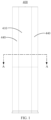
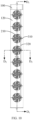
FIG. 1 is a schematic view of a floor-standing air conditioner in a power-off mode according to an embodiment of the present disclosure. -
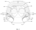
FIG. 2 is a sectional view along line A-A inFIG. 1 . -
FIG. 3 is a schematic view of the floor-standing air conditioner in a normal air supply mode inFIG. 1 . -
FIG. 4 is a front view of the floor-standing air conditioner inFIG. 3 . -
FIG. 5 is a sectional view along line B-B inFIG. 4 . -
FIG. 6 is a schematic view of the floor-standing air conditioner in a breezeless mode inFIG. 1 . -
FIG. 7 is a front view of the floor-standing air conditioner inFIG. 6 . -
FIG. 8 is a sectional view along line C-C inFIG. 7 . -
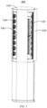
FIG. 9 is a schematic view of an air dispersing device according to an embodiment of the present disclosure. -
FIG. 10 is a rear view of the air dispersing device inFIG. 9 . -
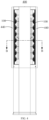
FIG. 11 is a sectional view along line D1-D1 inFIG. 10 . -
FIG. 12 is an enlarged view of P1 inFIG. 11 . -
FIG. 13 is a sectional view along line D2-D2 inFIG. 10 . -
FIG. 14 is an enlarged view of P2 inFIG. 13 . -
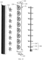
FIG. 15 is a schematic exploded structure view of the air dispersing device inFIG. 9 . -
FIG. 16 is another schematic exploded structure view of the air dispersing device from another perspective inFIG. 15 . -
FIG. 17 is an enlarged view of P3 inFIG. 15 . -
FIG. 18 is a schematic structural view of a movable impeller inFIG. 15 . -
FIG. 19 is a schematic structural view of a louver inFIG. 15 . -
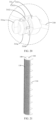
FIG. 20 is an enlarged view of P4 inFIG. 19 . -
FIG. 21 is a schematic structural view of the air dispersing device after the movable impeller is disassembled inFIG. 15 . -
FIG. 22 is a schematic view of the air dispersing device from another perspective inFIG. 21 . -
FIG. 23 is a rear view of the air dispersing device inFIG. 22 . -
FIG. 24 is a sectional view along line E1-E1 inFIG. 23 . -
FIG. 25 is a sectional view along line E2-E2 inFIG. 23 . -
Reference number Name Reference number Name 100 air dispersing frame 223 installation groove 110 first air dispersing plate 300 louver assembly 120 second air dispersing plate 310 louver 121 ventilation opening 311 connecting shaft 130 air cavity 3111 elastic arm 200 air dispersing module 311a clamping hook 210 movable impeller 311b positioning groove 211 hub 3112 separation groove 212 movable blade 320 connecting rod 213 installation portion 330 driver 214 connecting hole 400 floor-standing air conditioner 214a clamping groove 410 shell 214b positioning portion 411 air outlet 221 hub 430 turbine 222 stationary blade 440 damper - The realization of the objective, functional characteristics, and advantages of the present disclosure are further described with reference to the accompanying drawings.
- The technical solutions of the exemplary embodiments of the present disclosure will be described clearly in the following with reference to the accompanying drawings. It is obvious that these exemplary embodiments described are only some rather than all of the embodiments of the present disclosure. Based on these exemplary embodiments of the present disclosure, all other embodiments obtained by those skilled in the art without creative efforts shall fall within the scope of the present disclosure.
- It should be noted that all the directional indications (such as up, down, left, right, front, rear...) in the embodiments of the present disclosure are only used to explain the relative positional relationship, movement, or the like of the components in a certain posture (as shown in the drawings). If the specific posture changes, the directional indication will change accordingly.
- Besides, the descriptions associated with, e.g., "first" and "second," in the present disclosure are merely for descriptive purposes, and cannot be understood as indicating or suggesting relative importance or impliedly indicating the number of the indicated technical feature. Therefore, the feature associated with "first" or "second" can expressly or impliedly include at least one such feature. In addition, the technical solutions of the various embodiments can be combined with each other, but the combinations must be based on the realization of those skilled in the art. When the combination of technical solutions is contradictory or cannot be achieved, it should be considered that such a combination of technical solutions does not exist, nor does it fall within the scope of the present disclosure.
- The present disclosure provides embodiments of an air dispersing device. The air dispersing device is configured to improve the air dispersing effect in the breezeless mode, thereby improving the comfort of the air dispersing device. The air dispersing device can be used as a device for dispersing airflows outwards in the air-outlet device. The air-outlet device can be an air conditioner, an air cleaner or other equipment with air-outlet functions. To avoid redundant description, in the following embodiments, the air dispersing device applied in the floor-standing
air conditioner 400 is mainly used as an example for introduction and description. - As shown in
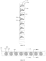
FIGS. 9 to 11 , in the air dispersing device of an embodiment of the present disclosure, the air dispersing device includes anair dispersing frame 100 and anair dispersing module 200. Theair dispersing frame 100 includes a firstair dispersing plate 110 and a secondair dispersing plate 120. Anair cavity 130 is formed between the firstair dispersing plate 110 and the secondair dispersing plate 120. An air dispersing hole is provided on the firstair dispersing plate 110, and aventilation opening 121 is provided on the secondair dispersing plate 120. Theair dispersing module 200 includes amovable impeller 210, and themovable impeller 210 is rotatably provided in theair cavity 130. Themovable impeller 210 is configured to disperse airflows. - As shown in
FIGS. 11 to 13 , theair dispersing frame 100 is rotatably installed on the air conditioner. In this way, when it is in operation, theair dispersing frame 100 can be switched to disperse airflows outwards through the firstair dispersing plate 110 or the secondair dispersing plate 120, thereby to realize working in different breezeless air supply modes. The firstair dispersing plate 110 and the secondair dispersing plate 120 can be integrally manufactured, or manufactured separately and subsequently assembled together. To reduce the molding difficulty and facilitate the manufacture, the firstair dispersing plate 110 and the secondair dispersing plate 120 of theair dispersing frame 100 are manufactured separately and subsequently detachably assembled together. - As for the first
air dispersing plate 110, a plurality of air dispersing holes are provided on the firstair dispersing plate 110, and the plurality of air dispersing holes are distributed on the surface of the firstair dispersing plate 110. After passing through the firstair dispersing plate 110, the airflows are dispersed into wisps of filamentous airflows, thereby reducing the air speed of the airflows and making the draft feeling comfortable. It should be noted that the air dispersing holes of the firstair dispersing plate 110 are micro holes with small apertures. The diameter of the air dispersing hole can be designed in a range of 2 mm to 5 mm. In this case, the draft feeling of the air dispersed by the firstair dispersing plate 110 is relatively comfortable, and a comfortable and breezeless air supply mode can be realized. In some embodiments, the diameter of the air dispersing hole on the firstair dispersing plate 110 can be designed in a range of 5 mm to 10 mm. In this case, the draft feeling of the air dispersed by the firstair dispersing plate 110 is relatively soft, and a soft and breezeless air supply mode can be realized. - As for the second
air dispersing plate 120, a plurality ofventilation openings 121 are provided on the secondair dispersing plate 120, and the plurality ofventilation openings 121 are distributed at intervals along a lengthwise direction of the secondair dispersing plate 120. It should be noted that the diameter of theventilation opening 121 is greater than the opening diameter of the air dispersing hole. Theventilation opening 121 can be in a circular shape, an oval shape or a square shape, which is not limited here. In some embodiments, theventilation opening 121 is in a circular shape. The number of theventilation openings 121 can be 2 to 10, which is not limited and can be set according to the size of the air conditioner. In addition, air dispersing holes may also be provided on the secondair dispersing plate 120, and the plurality of air dispersing holes are distributed around theventilation opening 121. In this case, the airflows can not only pass through theventilation opening 121 of the secondair dispersing plate 120, but also can be dispersed through the air dispersing hole on the secondair dispersing plate 120. - For the
air dispersing module 200, themovable impeller 210 of theair dispersing module 200 is rotatably provided in theair cavity 130 between the firstair dispersing plate 110 and the secondair dispersing plate 120. The rotation axis of themovable impeller 210 is configured to extend along a direction from the firstair dispersing plate 110 to the secondair dispersing plate 120. When the airflow passes through themovable impeller 210, themovable impeller 210 is configured to make the airflows rotatedly dispersed. Thus, the airflow is rotatedly dispersed around the periphery of themovable impeller 210. In this way, the air supply range is effectively increased and the air speed is reduced, thereby effectively reducing the draft feeling and improving the effect of the breezeless feeling. - For the assembly structure of the
movable impeller 210, themovable impeller 210 can be rotatably connected to the firstair dispersing plate 110 or the secondair dispersing plate 120. Or an installation bracket is provided in theair cavity 130 between the firstair dispersing plate 110 and the secondair dispersing plate 120, and themovable impeller 210 is rotatably connected to the installation bracket. Optionally, themovable impeller 210 is rotatably connected to the secondair dispersing plate 120, and themovable impeller 210 can be directly connected to the secondair dispersing plate 120. Or a supporting structure is provided on the secondair dispersing plate 120, and themovable impeller 210 can be rotatably connected to the supporting structure. The supporting structure can be a grilling frame, a cross bracket or a stationary impeller (described in the following paragraphs) and the like. - In the technical solution of the present disclosure, the
air dispersing module 200 is provided on theair dispersing frame 100 of the air dispersing device. Theair dispersing frame 100 includes a secondair dispersing plate 120 provided with anair cavity 130 between the firstair dispersing plate 110 and the secondair dispersing plate 120. An air dispersing hole is provided on the firstair dispersing plate 110, and aventilation opening 121 is provided on the secondair dispersing plate 120. Themovable impeller 210 of theair dispersing module 200 is rotatably provided in theair cavity 130. Themovable impeller 210 is opposite to theventilation opening 121. In this way, when the air dispersing device is working, themovable impeller 210 is configured to rotate to disperse airflows, which not only can disperse the airflow to reduce the air speed, but also can increase the airflow dispersing range. - Compared with the conventional operation of air being dispersed by the single-layer air dispersing plate, in the present disclosure, the airflow in the air dispersing device can be dispersed at least twice successively through the
air dispersing frame 100 and theair dispersing module 200. In this way, not only the air speed is effectively reduced and the air supply range is increased, but also the air dispersing effect in the breezeless mode can be improved, thereby improving the comfort of the air dispersing device. In addition, the airflow passing through the secondair dispersing plate 120 will be rotatedly dispersed by themovable impeller 210 of theair dispersing module 200. The air speed of the dispersed airflow is reduced, and the airflows will not directly impact the firstair dispersing plate 110 in a concentrated manner. In this case, it is not easy for the airflow to impact on the firstair dispersing plate 110 and generate noise, which helps to reduce the noise in a breezeless mode. - As shown in
FIG. 14 ,FIG. 16 and FIG. 17 , based on the above-mentioned embodiments, themovable impeller 210 includes ahub 211 and a plurality ofmovable blades 212 provided at intervals along the circumference of thehub 211. The plurality ofmovable blades 212 are all bent towards the same circumferential direction. Thus, after passing through themovable impeller 210, the airflow is guided by themovable blade 212 of themovable impeller 210 to spiral towards the same direction and flow forward, thereby improving the effect of theair dispersing module 200 to disperse the airflow forward. Thehub 211 of themovable impeller 210 is rotatably installed on theventilation opening 121. As mentioned above, theventilation opening 121 can be provided with a supporting structure, and themovable impeller 210 is rotatably connected to the supporting structure. The supporting structure can be a grilling frame, a cross bracket or a stationary impeller (described in the following paragraphs) and the like. - As shown in
FIG. 15 to FIG. 17 , in an embodiment, theair dispersing module 200 further includes astationary impeller 220 opposite to themovable impeller 210. Thestationary impeller 220 is provided at theventilation opening 121. The stationary impeller and the secondair dispersing plate 120 are integrally manufactured, or manufactured separately and subsequently assembled together (the method for manufacturing the stationary impeller and the secondair dispersing plate 120 integrally can be referred toFIG. 21 to FIG. 25 ). That is, the stationary impeller and the secondair dispersing plate 120 can be integrally manufactured, or manufactured separately and subsequently assembled together. - In some embodiments, the stationary impeller includes a
hub 221 and a plurality ofstationary blades 222 provided at intervals along the circumference of thehub 221. The plurality ofstationary blades 222 are all bent towards a same circumferential direction. Ends of the plurality ofstationary blades 222 are connected to the peripheral wall of theventilation opening 121. In this way, the stationary impeller and the secondair dispersing plate 120 can be disassembled or assembled integrally. - Further, a plurality of
movable blades 212 of themovable impeller 210 are all bent towards the same circumferential direction. A plurality ofstationary blades 222 of the stationary impeller are all bent towards the same circumferential direction, and a bending direction of thestationary blade 222 is consistent with a bending direction of themovable blade 212. In this way, after the airflow passes through themovable impeller 210, the rotating and dispersing direction of the airflows can be consistent with the rotating and dispersing direction of the airflows guided by thestationary blades 222. Thus, the airflow is first guided by thestationary blades 222 and thus has the rotating and dispersing potential energy. Driven by the rotating and dispersing potential energy, the airflow enters themovable impeller 210 smoothly. Then driven by themovable blades 212 of themovable impeller 210 successively, the airflow is rotatedly dispersed along the same direction. In this way, the airflow not only has the potential energy to flow forward, but also has the potential energy to rotate and disperse around the circumference of themovable impeller 210, thereby realizing an effect that the larger air volume is blown out forward but the draft feeling is soft. - In an embodiment, a side surface of the second
air dispersing plate 120 facing the firstair dispersing plate 110 is provided with an air guiding ring, and the air guiding ring is configured to protrude from a periphery of theventilation opening 121 towards the firstair dispersing plate 110. The air guiding ring can guide more air into theventilation opening 121, to increase the air flow of airflows passing through the stationary impeller and increase the air dispersing amount in a breezeless mode. In addition, the inner wall of the air guiding ring has a larger surface area, on which the stationary impeller can be installed, thereby reducing the installation difficulty of the stationary impeller. - Further, the
movable impeller 210 is opposite to the stationary impeller. When the breezeless mode is turned on, the airflow is first introduced from theventilation opening 121 of the secondair dispersing plate 120 to theair cavity 130 by the stationary impeller. During this process, the airflow flows along the rotation direction of thestationary blade 222 of the stationary impeller. Subsequently the airflow is guided to spiral along a same direction and flow forward. Thus, the airflow has a rotation potential energy before entering themovable impeller 210. Further, the airflow with the rotation potential energy continues to flow into themovable impeller 210, subsequently the airflow is forcefully driven by the rotation of themovable impeller 210 and further rotatedly dispersed, thereby effectively improving the rotating and dispersing effect of the airflows, and greatly improving the comfort when the air is dispersed in a breezeless mode. By a cooperation of the stationary impeller and themovable impeller 210, more airflows can be guided to pass through the air dispersing device, thereby effectively increasing the air output in the breezeless mode. - As shown in
FIG. 16 to FIG. 18 , based on this, thehub 211 of themovable impeller 210 can be rotatably installed on thehub 221 of the stationary impeller. Thus, no additional installation bracket for installing themovable impeller 210 is required. In an embodiment, ahub 211 of themovable impeller 210 is provided with aninstallation portion 213, and theinstallation portion 213 is rotatably installed on ahub 221 of the stationary impeller. Thehub 221 of the stationary impeller is provided with aninstallation groove 223 for installing theinstallation portion 213 of themovable impeller 210. During assembly, theinstallation portion 213 of themovable impeller 210 is rotatably installed in theinstallation groove 223 of the stationary impeller, to enable themovable impeller 210 to rotate around theinstallation groove 223 of the stationary impeller through theinstallation portion 213. - As for the rotating and driving manner of the
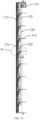
movable impeller 210, themovable impeller 210 may be driven to rotate by the airflow entering theventilation opening 121. Or adriver 330 is provided in themovable impeller 210 and configured to drive themovable impeller 210 to rotate. As shown inFIG. 13 to FIG. 15 , in this embodiment, the air dispersing device further includes alouver assembly 300. Thelouver assembly 300 is provided on a side of the secondair dispersing plate 120 away from the firstair dispersing plate 110, andlouvers 310 of thelouver assembly 300 are linked with themovable impeller 210. That is, themovable impeller 210 can be driven to rotate by thelouver assembly 300. - As shown in
FIG. 13 ,FIG. 15 andFIG. 19 , in an embodiment, thelouver assembly 300 includes a connectingrod 320 and a plurality oflouvers 310 linked with one another through the connectingrod 320. Thelouver 310 is provided with a connectingshaft 311, and the connectingshaft 311 is configured to pass through theventilation opening 121 and connect to themovable impeller 210, to make themovable impeller 210 link with thelouver 310. Since the stationary impeller is provided at theventilation opening 121, to avoid interference between the two, the connectingshaft 311 configured to pass through the stationary impeller is connected to thehub 211 of themovable impeller 210. - In some embodiments, a plurality of
louvers 310 are distributed at intervals along the lengthwise direction of theair dispersing frame 100. The connectingrod 320 is shaped as a long strip and is configured to extend along the lengthwise direction of theair dispersing frame 100 and connect the plurality oflouvers 310 sequentially. Eachmovable impeller 210 corresponds to at least one of thelouvers 310, and themovable impeller 210 is connected to thecorresponding louver 310. When the connectingrod 320 moves upward and downward, thelouver 310 is driven to swing upward and downward to discharge air in an up-down direction. During the swinging oflouvers 310 upward and downward, the connectingshaft 311 of thelouvers 310 rotates relative to the stationary impeller, and themovable impeller 210 is driven by the connectingshaft 311 to rotate synchronously. In this way, no additional driver for driving themovable impeller 210 is required, thereby the air conditioner can help to save costs by reducing the number ofdrivers 330 used by the air dispersing device. - As shown in
FIG. 14 ,FIG. 18 and FIG. 19 , in an embodiment, to facilitate the connection between thelouvers 310 and themovable impeller 210, in an embodiment, ahub 211 of themovable impeller 210 is provided with a connectinghole 214 for connecting the connectingshaft 311. The connectingshaft 311 is provided with aseparation groove 3112 along an axial direction of the connectingshaft 311. Theseparation groove 3112 is configured to divide the connectingshaft 311 into two oppositeelastic arms 3111, and the twoelastic arms 3111 are clamped and fixed on an inner wall of the connectinghole 214. - In some embodiments, the connecting
shaft 311 is provided with aseparation groove 3112, which can make the twoelastic arms 3111 of the connectingshaft 311 elastically deform along the radial direction of the connectingshaft 311, to obtain a better tensioning effect. When thelouvers 310 and themovable impeller 210 are connected to each other, the twoelastic arms 3111 can be pinched first to make the twoelastic arms 3111 close to each other and the diameter of the connectingshaft 311 decreased, thereby reducing resistance of the connectingshaft 311 extending into the connectinghole 214 of themovable impeller 210. In this case, the connectingshaft 311 can be inserted into the connectinghole 214 accurately and smoothly. After the connectingshaft 311 is inserted in place, the twoelastic arms 3111 are released and have a tendency to expand outwards. Subsequently the twoelastic arms 3111 are clung to the inner wall of the connectinghole 214, as well as being clamped to the inner wall of the connectinghole 214, which makes it difficult for the connectingshaft 311 to fall off from the connectinghole 214. - As for the clamp manner and the connection manner between the
elastic arms 3111 and the connectinghole 214, a buckle structure that cooperates with each other may be provided on theelastic arm 3111 and the connectinghole 214, to make theelastic arm 3111 and the connectinghole 214 clamped and matched with each other. In this embodiment, optionally, an end of theelastic arm 3111 is provided with aclamping hook 311a, and the inner wall of the connectinghole 214 is provided with a clampinggroove 214a. Theclamping hook 311a is configured to clamp with the clampinggroove 214a. - In the above-mentioned process of connecting the
louvers 310 and themovable impeller 210, when theclamping hook 311a at the end of the connectingshaft 311 of thelouver 310 reaches the clampinggroove 214a, the connectingshaft 311 is inserted in place. At this time, the twoelastic arms 3111 are released, subsequently the twoelastic arms 3111 expand outwards to make theclamping hook 311a at the end of the connectingshaft 311 clamped into the clampinggroove 214a. In this case, it is difficult for the connectingshaft 311 to overcome the binding force of the clampinggroove 214a and fall off reversely. When thelouver 310 needs to be disassembled, the twoelastic arms 3111 of the connectingshaft 311 are pinched again to make the diameter of the connectingshaft 311 decreased and the clamping hooks 311a of the twoelastic arms 3111 separated from the side surfaces of the clampinggroove 214a. In this case, theelastic arm 3111 can be pulled out smoothly from the connectinghole 214, that is, thelouver 310 can be disassembled from themovable impeller 210. - Further, to improve the firmness of the connection between the
louver 310 and themovable impeller 210, the inner wall of the connectinghole 214 is further provided with one of apositioning portion 214b or apositioning groove 311b. A peripheral side of theelastic arm 3111 is provided with the other one of apositioning portion 214b or apositioning groove 311b. Thepositioning portion 214b is clamped and matched with the positioning groove 311b.In some embodiments, the inner wall of the connection hole is provided with apositioning portion 214b, and the inner wall of the connection hole is provided with apositioning groove 311b. In the above description, after theclamping hook 311a of theelastic arm 3111 is clamped with the side surface of the clampinggroove 214a, thepositioning portion 214b on the top surface of the lug boss is just clamped into thepositioning groove 311b on the side surface of theelastic arm 3111. Thus, the axial movement of the connectingshaft 311 is double restricted, and the firmness of the connection between thelouver 310 and themovable impeller 210 is greatly improved. - In an embodiment, for driving the
louvers 310 to swing conveniently, thelouver assembly 300 further includes adriver 330. Thedriver 330 is installed on theair dispersing frame 100 and connected to the connectingrod 320. Thedriver 330 is configured to drive the connectingrod 320 to move upward and downward, and subsequently thelouver 310 is driven to swing by the connectingrod 320. - As shown in
FIG. 10 ,FIG.11 andFIG. 13 , based on any one of the above embodiments, theair dispersing frame 100 is provided with a rotation axis extending along the lengthwise direction of theair dispersing frame 100. Theair dispersing frame 100 is rotatably installed on theair outlet 411 of the floor-standingair conditioner 400 around the rotation axis. In an embodiment, the rotation axis is provided on the side of the secondair dispersing plate 120 away from the firstair dispersing plate 110, to make the distance between theair dispersing module 200 and the firstair dispersing plate 110 relatively small. In this case, after the airflow passing through one of theair dispersing module 200 and the firstair dispersing plate 110 is dispersed, the airflow reaches the other one of theair dispersing module 200 and the firstair dispersing plate 110 as soon as possible to be further dispersed, thereby effectively improving the breezeless feeling effect. - In an embodiment, as for the first
air dispersing plate 110 and the secondair dispersing plate 120, both the firstair dispersing plate 110 and the secondair dispersing plate 120 can be shaped in flat plates, or arc plates. In this embodiment, the firstair dispersing plate 110 and the secondair dispersing plate 120 are configured to protrude outwards towards a same side and are arc-shaped. The firstair dispersing plate 110 is taken as an example. The plate surface of the firstair dispersing plate 110 is arc-shaped to make the firstair dispersing plate 110 obtain a larger air dispersing area. In this way, the air dispersing area of the firstair dispersing plate 110 can be effectively increased, thereby increasing the air dispersing range of the firstair dispersing plate 110. Of course, in other embodiments, the firstair dispersing plate 110 is configured to protrude outwards and is arc-shaped, and the secondair dispersing plate 120 is plate-shaped. - As shown in
FIG. 13 , in an embodiment, two side edges of the firstair dispersing plate 110 extending along a lengthwise direction of the firstair dispersing plate 110 correspond to two side edges of the secondair dispersing plate 120 extending along a lengthwise direction of the secondair dispersing plate 120, and the firstair dispersing plate 110 and the secondair dispersing plate 120 are closed, to form anair cavity 130 between the firstair dispersing plate 110 and the secondair dispersing plate 120. On the cross-section of theair dispersing frame 100 cut by a plane perpendicular to the lengthwise direction of theair dispersing frame 100, theair cavity 130 is crescent-shaped. The airflow can only enter from theair dispersing module 200 and pass through theair cavity 130, and is subsequently dispersed from the firstair dispersing plate 110. - Based on any one of the above-mentioned embodiments, two ends of the
air dispersing frame 100 are provided with a rotation shaft extending along the lengthwise direction of theair dispersing frame 100. Theair dispersing frame 100 is rotatably installed on the air conditioner through the rotation shaft. In this way, the air dispersing direction of theair dispersing frame 100 can be adjusted through the rotation of theair dispersing frame 100. - As shown in
FIG. 1 andFIG. 2 , the present disclosure further provides a floor-standingair conditioner 400. The floor-standingair conditioner 400 includes ashell 410 and an air dispersing device. Theshell 410 is provided with anair outlet 411, and theair outlet 411 is provided with adamper 440. The air dispersing device is rotatably installed on theair outlet 411. The rotation axis of the air dispersing device is configured to extend along the lengthwise direction of theair outlet 411. The specific structure of the air dispersing device can be referred to the above-mentioned embodiments. Since the floor-standingair conditioner 400 adopts all the technical solutions of all the above-mentioned embodiments, the floor-standingair conditioner 400 also has all the beneficial effects brought by the technical solutions of the above-mentioned embodiments, which will not be repeated here. - As shown in
FIG. 1 andFIG. 2 , in an embodiment, the floor-standingair conditioner 400 further includes a heat exchanger and aturbine 430. The heat exchanger provided between the air inlet and theturbine 430 is configured to partially surround theturbine 430. The number ofturbines 430 may be one or two. As shown inFIG. 1 andFIG. 2 , the number ofturbines 430 is two, and the twoturbines 430 are respectively configured to disperse air to the twocorresponding air outlets 411. Eachair outlet 411 in the air outlet flue is provided with an air dispersing device. In an embodiment, the floor-standingair conditioner 400 has a power-off mode, a normal air supply mode, and a breezeless mode. - As shown in
FIG. 1 andFIG. 2 , in the power-off mode, the air dispersing device is configured to rotate until the firstair dispersing plate 110 is located at the innermost side of theair outlet 411. At this time, both the firstair dispersing plate 110 and the secondair dispersing plate 120 of theair dispersing frame 100 of the air dispersing device are stored inside theair outlet 411, to prevent theair dispersing frame 100 from interfering with thedamper 440 to close theair outlet 411. - As shown in
FIG. 3 andFIG. 4 , in the normal air supply mode, the air dispersing device is configured to rotate until the firstair dispersing plate 110 and the secondair dispersing plate 120 are located on opposite sides of theair outlet 411. At this time, the firstair dispersing plate 110 and the secondair dispersing plate 120 are stored near the inner wall of theair outlet 411, and the ventilation cross-section area of the air outlet flue occupied by the firstair dispersing plate 110 and the secondair dispersing plate 120 is small, which is not easy to prevent the airflow from blowing out, thereby realizing the conventional air supply. - As shown in
FIG. 5 andFIG. 9 , in the breezeless mode, the air dispersing device is configured to rotate until the firstair dispersing plate 110 faces the outside of theair outlet 411. At this time, the firstair dispersing plate 110 and the secondair dispersing plate 120 are unfolded on the ventilation cross-section of the air outlet flue. In this case, the airflow blown out from the air outlet flue is configured to pass through the secondair dispersing plate 120, theair dispersing module 200, the firstair dispersing plate 110. The air gets intercepted along the way, thereby realizing the breezeless air supply mode. - The above are only some embodiments of the present disclosure, and do not limit the scope of the present disclosure thereto. Under the inventive concept of the present disclosure, any equivalent mechanism transformation made according to the description and drawings of the present disclosure, or direct/indirect application in other related technical fields fall within the scope of the present disclosure.
Claims (18)
- An air dispersing device, installed at an air outlet of an air conditioner, characterized by comprising: an air dispersing frame comprising a first air dispersing plate and a second air dispersing plate, wherein an air cavity is formed between the first air dispersing plate and the second air dispersing plate, an air dispersing hole is provided on the first air dispersing plate, and a ventilation opening is provided on the second air dispersing plate; and an air dispersing module comprising a movable impeller, wherein the movable impeller is rotatably provided in the air cavity, and the movable impeller is configured to disperse airflows.
- The air dispersing device of claim 1, wherein: the air dispersing module further comprises a stationary impeller provided at the ventilation opening, and the stationary impeller and the second air dispersing plate are integrally manufactured, or manufactured separately and assembled together.
- The air dispersing device of claim 2, wherein the movable impeller is opposite to the stationary impeller.
- The air dispersing device of claim 3, wherein: a hub of the movable impeller is provided with an installation portion, and the installation portion is rotatably installed on a hub of the stationary impeller.
- The air dispersing device of claim 1, further comprising a louver assembly, wherein: the louver assembly is provided on a side of the second air dispersing plate away from the first air dispersing plate, and louvers of the louver assembly are linked with the movable impeller.
- The air dispersing device of claim 5, wherein: the louver assembly comprises a connecting rod and a plurality of louvers linked with one another through the connecting rod, the louver is provided with a connecting shaft, and the connecting shaft is configured to pass through the ventilation opening and connect to the movable impeller, to make the movable impeller link with the louver.
- The air dispersing device of claim 6, wherein: a hub of the movable impeller is provided with a connecting hole for connecting the connecting shaft; and the connecting shaft is provided with a separation groove along an axial direction of the connecting shaft, the separation groove is configured to divide the connecting shaft into two opposite elastic arms, and the two opposite elastic arms are clamped and fixed on an inner wall of the connecting hole.
- The air dispersing device of claim 7, wherein: an end of an elastic arm of the two opposite elastic arms is provided with a clamping hook, the inner wall of the connecting hole is provided with a clamping groove, and the clamping hook is configured to clamp with the clamping groove.
- The air dispersing device of claim 8, wherein: the inner wall of the connecting hole is further provided with one of a positioning portion or a positioning groove, a peripheral side of the elastic arm is provided with the other one of a positioning portion or a positioning groove, and the positioning portion is clamped with the positioning groove.
- The air dispersing device of any one of claims 2 to 4, wherein: a plurality of movable blades of the movable impeller are all bent towards a same circumferential direction, a plurality of stationary blades of the stationary impeller are all bent towards a same circumferential direction, and a bending direction of the stationary blade is consistent with a bending direction of the movable blade.
- The air dispersing device of any one of claims 2 to 9, wherein: a side surface of the second air dispersing plate facing the first air dispersing plate is provided with an air guiding ring, and the air guiding ring is configured to protrude from a periphery of the ventilation opening towards the first air dispersing plate.
- The air dispersing device of any one of claims 1 to 9, wherein: a plate surface of the second air dispersing plate is provided with a plurality of air dispersing holes, and the plurality of air dispersing holes are distributed around the ventilation opening.
- The air dispersing device of any one of claims 1 to 9, wherein: the air dispersing frame is provided with a rotation axis extending along a lengthwise direction of the air dispersing frame, and the rotation axis is provided at a side of the second air dispersing plate away from the first air dispersing plate.
- The air dispersing device of claim 13, wherein: the first air dispersing plate is configured to protrude outwards and is arc-shaped, and the second air dispersing plate is plate-shaped.
- The air dispersing device of claim 13, wherein both the first air dispersing plate and the second air dispersing plate are configured to protrude outwards towards a same side and are arc-shaped.
- The air dispersing device of claim 14 or claim 15, wherein: two side edges of the first air dispersing plate extending along a lengthwise direction of the first air dispersing plate correspond to two side edges of the second air dispersing plate extending along a lengthwise direction of the second air dispersing plate, and the first air dispersing plate and the second air dispersing plate are arranged in a closed manner.
- The air dispersing device of any one of claims 1 to 9, wherein a diameter of the air dispersing hole on the first air dispersing plate is in a range of 5 mm to 10 mm.
- A floor-standing air conditioner characterized by comprising: a shell provided with an air outlet; and the air dispersing device of claim 1 to 17, wherein the air dispersing device is rotatably installed at the air outlet.
Applications Claiming Priority (3)
| Application Number | Priority Date | Filing Date | Title |
|---|---|---|---|
| CN202011044918.8A CN114322284B (en) | 2020-09-28 | 2020-09-28 | Air dispersion device and floor-standing air conditioner |
| CN202022179996.0U CN212511728U (en) | 2020-09-28 | 2020-09-28 | Air diffusing device and floor type air conditioner |
| PCT/CN2021/089749 WO2022062385A1 (en) | 2020-09-28 | 2021-04-26 | Air diffusion apparatus and floor-mounted air conditioner |
Publications (2)
| Publication Number | Publication Date |
|---|---|
| EP4191156A1 true EP4191156A1 (en) | 2023-06-07 |
| EP4191156A4 EP4191156A4 (en) | 2024-02-07 |
Family
ID=80844814
Family Applications (1)
| Application Number | Title | Priority Date | Filing Date |
|---|---|---|---|
| EP21870774.3A Pending EP4191156A4 (en) | 2020-09-28 | 2021-04-26 | FLOOR MOUNTED AIR DIFFUSION DEVICE AND AIR CONDITIONER |
Country Status (3)
| Country | Link |
|---|---|
| US (1) | US20230175708A1 (en) |
| EP (1) | EP4191156A4 (en) |
| WO (1) | WO2022062385A1 (en) |
Family Cites Families (12)
| Publication number | Priority date | Publication date | Assignee | Title |
|---|---|---|---|---|
| US4426918A (en) * | 1980-04-25 | 1984-01-24 | Lambert Robert R | Proportioning air diffuser and system |
| KR101840697B1 (en) * | 2015-07-17 | 2018-05-04 | 삼성전자 주식회사 | Air Conditional |
| CN108679792A (en) * | 2016-08-31 | 2018-10-19 | 芜湖美智空调设备有限公司 | Air conditioner room unit and its control method |
| KR102543848B1 (en) * | 2017-07-21 | 2023-06-19 | 삼성전자주식회사 | Air conditioner |
| CN207146852U (en) * | 2017-08-21 | 2018-03-27 | 广东美的制冷设备有限公司 | Deep bead, indoor apparatus of air conditioner and air conditioner |
| CN110345625B (en) * | 2019-08-09 | 2023-06-16 | 广东美的制冷设备有限公司 | Air conditioner, control method and storage medium for air conditioner |
| CN211575272U (en) * | 2020-02-28 | 2020-09-25 | 广东美的制冷设备有限公司 | Air conditioner indoor unit and air conditioner having the same |
| CN211575289U (en) * | 2020-02-28 | 2020-09-25 | 广东美的制冷设备有限公司 | Cabinet air conditioner interior unit and air conditioner having the same |
| CN211575290U (en) * | 2020-02-28 | 2020-09-25 | 广东美的制冷设备有限公司 | Cabinet air conditioner interior unit and air conditioner having the same |
| CN111380106A (en) * | 2020-02-28 | 2020-07-07 | 广东美的制冷设备有限公司 | Cabinet air conditioner indoor unit and air conditioner with same |
| CN111189117A (en) * | 2020-02-28 | 2020-05-22 | 广东美的制冷设备有限公司 | Cabinet air conditioner indoor unit and air conditioner with same |
| CN212511728U (en) * | 2020-09-28 | 2021-02-09 | 广东美的制冷设备有限公司 | Air diffusing device and floor type air conditioner |
-
2021
- 2021-04-26 EP EP21870774.3A patent/EP4191156A4/en active Pending
- 2021-04-26 WO PCT/CN2021/089749 patent/WO2022062385A1/en not_active Ceased
-
2023
- 2023-01-31 US US18/103,804 patent/US20230175708A1/en active Pending
Also Published As
| Publication number | Publication date |
|---|---|
| EP4191156A4 (en) | 2024-02-07 |
| US20230175708A1 (en) | 2023-06-08 |
| WO2022062385A1 (en) | 2022-03-31 |
Similar Documents
| Publication | Publication Date | Title |
|---|---|---|
| CN214276108U (en) | Air diffuser and floor-standing air conditioner | |
| CN108332293B (en) | Cabinet air conditioner and air conditioner | |
| AU719205B2 (en) | Air conditioner indoor unit | |
| CN209763304U (en) | Indoor unit of air conditioner | |
| CN209558544U (en) | Air conditioner | |
| CN114322095A (en) | Indoor unit of air conditioner and floor type air conditioner | |
| CN212319882U (en) | Air conditioner indoor unit and air conditioner | |
| EP4191156A1 (en) | Air diffusion apparatus and floor-mounted air conditioner | |
| CN213480548U (en) | Air guide device and air conditioner | |
| CN212618758U (en) | Floor type air conditioner indoor unit and air conditioner | |
| CN114322284B (en) | Air dispersion device and floor-standing air conditioner | |
| CN222352516U (en) | Air guide structure, panel assembly, air conditioner indoor unit and heating ventilation system | |
| CN211854217U (en) | Floor type air conditioner indoor unit and air conditioner | |
| CN212319885U (en) | Air conditioner indoor unit and air conditioner | |
| CN210638118U (en) | Air conditioner | |
| WO2020172940A1 (en) | Air conditioner indoor unit, air conditioner, and control method for air conditioner | |
| CN112880010A (en) | Air conditioner indoor unit and air conditioner | |
| CN216381915U (en) | Cross-flow fan and air conditioner with same | |
| CN114251732B (en) | Air conditioner indoor unit and air conditioner | |
| CN212511727U (en) | Air diffusing device and floor type air conditioner | |
| CN211650483U (en) | Floor-standing air conditioner indoor unit and air conditioner | |
| CN212746702U (en) | Air conditioner indoor unit and air conditioner | |
| CN213480384U (en) | duct machine | |
| CN213480547U (en) | Air guide device and air conditioner for air conditioner | |
| CN209181100U (en) | Ducting assembly and air conditioner with it |
Legal Events
| Date | Code | Title | Description |
|---|---|---|---|
| STAA | Information on the status of an ep patent application or granted ep patent |
Free format text: STATUS: THE INTERNATIONAL PUBLICATION HAS BEEN MADE |
|
| PUAI | Public reference made under article 153(3) epc to a published international application that has entered the european phase |
Free format text: ORIGINAL CODE: 0009012 |
|
| STAA | Information on the status of an ep patent application or granted ep patent |
Free format text: STATUS: REQUEST FOR EXAMINATION WAS MADE |
|
| 17P | Request for examination filed |
Effective date: 20230303 |
|
| AK | Designated contracting states |
Kind code of ref document: A1 Designated state(s): AL AT BE BG CH CY CZ DE DK EE ES FI FR GB GR HR HU IE IS IT LI LT LU LV MC MK MT NL NO PL PT RO RS SE SI SK SM TR |
|
| DAV | Request for validation of the european patent (deleted) | ||
| DAX | Request for extension of the european patent (deleted) | ||
| A4 | Supplementary search report drawn up and despatched |
Effective date: 20240108 |
|
| RIC1 | Information provided on ipc code assigned before grant |
Ipc: F24F 1/0014 20190101ALI20240102BHEP Ipc: F24F 1/005 20190101ALI20240102BHEP Ipc: F24F 13/15 20060101ALI20240102BHEP Ipc: F24F 13/08 20060101AFI20240102BHEP |
|
| STAA | Information on the status of an ep patent application or granted ep patent |
Free format text: STATUS: EXAMINATION IS IN PROGRESS |
|
| 17Q | First examination report despatched |
Effective date: 20251223 |