EP4191145A1 - Cooktop grate assembly - Google Patents
Cooktop grate assembly Download PDFInfo
- Publication number
- EP4191145A1 EP4191145A1 EP22210698.1A EP22210698A EP4191145A1 EP 4191145 A1 EP4191145 A1 EP 4191145A1 EP 22210698 A EP22210698 A EP 22210698A EP 4191145 A1 EP4191145 A1 EP 4191145A1
- Authority
- EP
- European Patent Office
- Prior art keywords
- grate
- heat shield
- cooktop
- gasket
- assembly
- Prior art date
- Legal status (The legal status is an assumption and is not a legal conclusion. Google has not performed a legal analysis and makes no representation as to the accuracy of the status listed.)
- Withdrawn
Links
- 230000014759 maintenance of location Effects 0.000 claims description 32
- 238000007789 sealing Methods 0.000 claims description 15
- 238000000034 method Methods 0.000 description 11
- 230000008901 benefit Effects 0.000 description 5
- 239000000463 material Substances 0.000 description 5
- 230000000712 assembly Effects 0.000 description 4
- 238000000429 assembly Methods 0.000 description 4
- 238000010411 cooking Methods 0.000 description 4
- 229920001296 polysiloxane Polymers 0.000 description 3
- 230000006835 compression Effects 0.000 description 2
- 238000007906 compression Methods 0.000 description 2
- 230000008878 coupling Effects 0.000 description 2
- 238000010168 coupling process Methods 0.000 description 2
- 238000005859 coupling reaction Methods 0.000 description 2
- 239000007788 liquid Substances 0.000 description 2
- 238000004519 manufacturing process Methods 0.000 description 2
- 230000000717 retained effect Effects 0.000 description 2
- 239000000919 ceramic Substances 0.000 description 1
- 238000004891 communication Methods 0.000 description 1
- 239000012530 fluid Substances 0.000 description 1
- 239000011521 glass Substances 0.000 description 1
- 239000002241 glass-ceramic Substances 0.000 description 1
- 238000003780 insertion Methods 0.000 description 1
- 230000037431 insertion Effects 0.000 description 1
- 230000000087 stabilizing effect Effects 0.000 description 1
- 230000000007 visual effect Effects 0.000 description 1
Images


Classifications
-
- F—MECHANICAL ENGINEERING; LIGHTING; HEATING; WEAPONS; BLASTING
- F24—HEATING; RANGES; VENTILATING
- F24C—DOMESTIC STOVES OR RANGES ; DETAILS OF DOMESTIC STOVES OR RANGES, OF GENERAL APPLICATION
- F24C15/00—Details
- F24C15/10—Tops, e.g. hot plates; Rings
- F24C15/107—Pan supports or grates therefor
-
- F—MECHANICAL ENGINEERING; LIGHTING; HEATING; WEAPONS; BLASTING
- F24—HEATING; RANGES; VENTILATING
- F24C—DOMESTIC STOVES OR RANGES ; DETAILS OF DOMESTIC STOVES OR RANGES, OF GENERAL APPLICATION
- F24C15/00—Details
- F24C15/34—Elements and arrangements for heat storage or insulation
-
- F—MECHANICAL ENGINEERING; LIGHTING; HEATING; WEAPONS; BLASTING
- F24—HEATING; RANGES; VENTILATING
- F24C—DOMESTIC STOVES OR RANGES ; DETAILS OF DOMESTIC STOVES OR RANGES, OF GENERAL APPLICATION
- F24C3/00—Stoves or ranges for gaseous fuels
- F24C3/08—Arrangement or mounting of burners
- F24C3/085—Arrangement or mounting of burners on ranges
Definitions
- the present disclosure generally relates to a grate assembly, and more specifically, to a grate assembly for a cooktop.
- a cooktop grate assembly includes a heat shield having an outer rim and a central plateau region offset from the outer rim by a connecting wall.
- the central plateau region defines an opening for receiving a burner assembly.
- a grate is positioned over the heat shield.
- the grate includes supports that extend over the central plateau region.
- a gasket is disposed adjacent to the heat shield. The gasket engages at least one of a base of the grate and feet of the supports to retain the grate in position relative to the heat shield.
- a grate assembly for a cooktop includes a heat shield with a central plateau region offset from an outer rim via a connecting wall.
- the heat shield has an interior surface oriented toward said cooktop and an exterior surface.
- a grate is selectively positioned over the heat shield.
- the grate includes a base disposed adjacent to the outer rim and supports extending from the base and over the central plateau region.
- a gasket is coupled to the heat shield. The gasket extends from proximate to the interior surface, through the heat shield, to proximate the exterior surface to engage the grate.
- a grate assembly for a cooktop includes a heat shield with an outer rim and a central plateau region.
- the heat shield includes a curved outer edge.
- a grate is positioned over the heat shield.
- the grate includes supports and each support has feet selectively positioned adjacent to the outer rim.
- a gasket is disposed partially below the heat shield. The gasket defines a groove configured to receive the curved outer edge of the heat shield. The feet of the grate are positioned on projections of the gasket to retain the grate in position relative to the heat shield.
- the terms “upper,” “lower,” “right,” “left,” “rear,” “front,” “vertical,” “horizontal,” and derivatives thereof shall relate to the disclosure as oriented in FIG. 1 .
- the term “front” shall refer to the surface of the element closer to an intended viewer, and the term “rear” shall refer to the surface of the element further from the intended viewer.
- the disclosure may assume various alternative orientations, except where expressly specified to the contrary.
- the specific devices and processes illustrated in the attached drawings, and described in the following specification are simply exemplary embodiments of the inventive concepts defined in the appended claims. Hence, specific dimensions and other physical characteristics relating to the embodiments disclosed herein are not to be considered as limiting, unless the claims expressly state otherwise.
- reference numeral 10 generally designates a grate assembly for a cooktop 12 that includes a heat shield 14 having an outer rim 16 and a central plateau region 18 offset from the outer rim 16 by a connecting wall 20.
- the central plateau region 18 defines an opening 22 for receiving a burner assembly 24.
- a grate 26 is positioned over the heat shield 14.
- the grate 26 includes supports 28, 30 that extend over the central plateau region 18.
- a gasket 32 is disposed adjacent to the heat shield 14. The gasket 32 engages at least one of a base 34 of the grate 26 and feet 36 of the supports 28, 30 to retain the grate 26 in position relative to the heat shield 14.
- the cooktop 12 is illustrated as a standalone unit that includes multiple burner assemblies 24. Each burner assembly 24 is associated with an individual grate assembly 10. Accordingly, each cooktop 12 includes multiple grate assemblies 10.
- the cooktop 12 may be constructed of a ceramic, a glass ceramic, or a glass material. The cooktop 12 may be included in a cooking appliance without departing from the teachings herein.
- each grate assembly 10 includes the heat shield 14, which is positioned on or adjacent to an upper surface 50 of the cooktop 12.
- the heat shields 14 may deflect or diffuse heat generated by the burner assemblies 24.
- the heat shields 14 may be advantageous for directing heat away from various components of the cooktop 12, including controls and electronic components 52.
- Each heat shield 14 includes the outer rim 16 disposed adjacent to the upper surface 50.
- the outer rim 16 may be disposed on the upper surface 50 or on the gasket 32 depending on the configuration of the gasket 32.
- Each heat shield 14 also includes the central plateau region 18, which defines the opening 22 for receiving the burner assembly 24.
- the burner assembly 24 extends from the cooktop 12 and through the opening 22.
- a burner cap 54 of the burner assembly 24 may be positioned on or adjacent to an exterior surface 60 of the central plateau region 18 of the heat shield 14 under the supports 28, 30 of the grate 26.
- the grates 26 are selectively positioned over the respective heat shields 14.
- the grates 26 include the base 34 configured to extend around the central plateau region 18.
- the base 34 of the grate 26 is a ring that follows the shape of the central plateau region 18 and the overall heat shield 14, which each defines a circular shape.
- the base 34 extends along the outer rim 16 adjacent to the connecting wall 20.
- the supports 28, 30 extend from the base 34 and are configured to extend over the central plateau region 18.
- the supports 28, 30 are configured to support a cooking receptacle over the burner assembly 24.
- the supports 28, 30 each form or define an arcuate shape. There are two supports 28, 30 in the illustrated configuration, with the supports 28, 30 being disposed on opposing sides of the opening 22. Accordingly, in certain aspects, the supports 28, 30 do not intersect with one another.
- the heat shield 14 generally defines indents 62 in which feet 36 of the supports 28, 30 of the grate 26 at least partially extend.
- the feet 36 are generally disposed on or adjacent to the outer rim 16 of the heat shield 14 and partially within the indents 62 defined by the heat shield 14.
- the feet 36 of the supports 28, 30 provide additional stability to the grate 26. Additionally, the feet 36 may extend beyond an outer edge 64 of the heat shield 14 and onto or over the upper surface 50 of the cooktop 12.
- the indents 62 provide a visual indicator for aligning the grate 26 relative to the heat shield 14. The indents 62 may also assist in retaining the position of the grate 26 relative to the heat shield 14.
- each grate assembly 10 includes the gasket 32 configured to retain the grate 26 in position relative to the heat shield 14.
- the gasket 32 is configured to lock the grate 26 in the selected position, thereby reducing movement of the grate 26, which consequently stabilizes the grate 26.
- the gasket 32 is configured as a plurality of wall inserts 70, which are configured to extend through the heat shield 14 to engage the grate 26.
- the illustrated grate assembly 10 includes four wall inserts 70; however, any practicable number of wall inserts 70 may be utilized without departing from the teachings herein.
- the connecting wall 20 of the heat shield 14 defines apertures 72 spaced at intervals around the heat shield 14.
- the apertures 72 may be positioned at substantially equal intervals about the connecting wall 20 or at any select locations.
- Each wall insert 70 extends through one of the respective apertures 72 defined by the connecting wall 20. In this way, each wall insert 70 is disposed at least partially under the heat shield 14 proximate to an interior surface 74 of the heat shield 14 and partially outside of the heat shield 14 proximate to the exterior surface 60.
- An interior portion 76 of the wall insert 70 abuts the interior surface 74 of the connecting wall 20, while an exterior portion 78 of the wall insert 70 abuts the exterior surface 60 of the connecting wall 20.
- the interior portion 76 and the exterior portion 78 are separated by a ledge or a groove 80.
- the grooves 80 is configured to receive the heat shield 14 to retain the wall inserts 70 within the apertures 72 of the connecting wall 20.
- the ledge may abut one of the exterior surface 60 and the interior surface 74 of the heat shield 14 to prevent the wall insert 70 from moving further through the aperture 72.
- the exterior portion 78 protrudes from the connecting wall 20 to engage the grate 26.
- the wall insert 70 engages an inner surface 82 of the base 34.
- the wall inserts 70 extend between the heat shield 14 and the base 34 of the grate 26 to provide an interference or frictional engagement with the grate 26, which is configured to retain the grate 26 in position relative to the heat shield 14.
- the base 34 may engage the wall inserts 70 and also be positioned substantially below the wall inserts 70. In this configuration, the base 34 has to move past a substantial portion of the wall inserts 70 to disengage from the heat shield 14, which provides greater stability and reduces movement of the grate 26.
- the exterior portions 78 of the wall inserts 70 may form a substantially hemispherical shape.
- the rounded shape may be advantageous for coupling the wall inserts 70 with the connecting wall 20.
- the rounded configuration of the exterior portion 78 may be advantageous for moving the grate 26 past the wall inserts 70 and on the heat shield 14.
- the rounded shape may provide less resistance when positioning the grate 26 on the outer rim 16 of the heat shield 14.
- the illustrated wall insert 70 is elongated, having a more rectangular configuration.
- the elongated wall insert 70 extends generally parallel with the outer rim 16 of the heat shield 14, which may provide an increased surface area for the grate 26 to engage.
- the increased surface area may provide a greater interference or frictional engagement for retaining the grate 26 in position relative to the heat shield 14.
- Each grate assembly 10 may include the more spherical wall inserts 70 illustrated in FIGS. 2-4 , the prism wall inserts 70 illustrated in FIG. 5 , or a combination thereof.
- the grate 26 includes the base 34 that is positioned on the outer rim 16 and extends along the connecting wall 20.
- the supports 28, 30 extend from the base 34 and are configured to extend over the central plateau region 18.
- the burner cap 54 of the burner assembly 24 is positioned on or adjacent to the exterior surface 60 of the central plateau region 18 below an intersection point 90 of the supports 28, 30.
- the supports 28, 30 extend across to the central plateau region 18 and couple with the base 34 on opposing sides of the burner assembly 24.
- the supports 28, 30 intersect with one another over the burner assembly 24.
- the supports 28, 30 each have feet 36 that extend into the indents 62, over the outer rim 16, and onto the upper surface 50 of the cooktop 12.
- the feet 36 define a step 92, forming two different portions of a bottom 94 of the feet 36.
- the step 92 allows a first portion of the bottom 94 of the feet 36 to be positioned on the upper surface 50 of the cooktop 12 ( FIG. 1 ) and the second portion to be positioned on the outer rim 16 of the heat shield 14.
- the feet 36 assist with aligning the grate 26 relative to the heat shield 14, as well as stabilizing the grate 26.
- the indents 62 and the apertures 72 of the heat shield 14 generally alternate with one another.
- the heat shield 14 defines four indents 62 and four apertures 72. Each aperture 72 is positioned between two adjacent indents 62. Accordingly, the grate 26 engages the heat shield 14 within the indents 62 and the wall inserts 70 engage the grates 26 between the feet 36.
- This configuration provides multiple engagement points between the grate 26 and the heat shield 14, as well as multiple engagement points between the grate 26 and the wall inserts 70 to increase the stability of the grate 26.
- the wall inserts 70 extend through the heat shield 14 to engage the grate 26 to retain the grate 26 in position relative to the heat shield 14. Additionally, the wall insert 70 may be constructed of an elastically deformable material, such as rubber or silicone, to provide the interference or frictional engagement with the grate 26. When the grate 26 is disposed on the outer rim 16, the wall inserts 70 may be slightly deformed by the base 34. The wall inserts 70 may apply a biasing force from the elastically deformable material toward the base 34 of the grate 26 when deformed, which assists in maintaining the engagement between the wall inserts 70 and the grate 26.
- an elastically deformable material such as rubber or silicone
- the wall inserts 70 may be constructed as spring-loaded pins.
- a spring may be disposed under the heat shield 14 and the pins may extend through the apertures 72 to engage the grate 26. The pins may be adjusted against a biasing force of the spring when engaged with the grate 26. Additional or alternative configurations of the wall inserts 70 may be utilized in the grate assembly 10 without departing from the teachings herein.
- the heat shield 14 includes the central plateau region 18 defining the opening 22 for the burner assembly 24.
- the heat shield 14 also includes the outer rim 16 coupled to the central plateau region 18 via the connecting wall 20. Further, the heat shield 14 defines the indents 62 for receiving the feet 36 of the grate 26.
- the connecting wall 20 may be free of the apertures 72 ( FIG. 3 ) while the outer rim 16 defines apertures 116 spaced about the central plateau region 18. In the illustrated configuration, the outer rim 16 defines four apertures 116.
- the gasket 32 is configured as a sealing insert 110.
- the sealing insert 110 includes a seal member 112 and retention features 114 extending from the seal member 112.
- the seal member 112 is configured to be disposed below the outer rim 16 of the heat shield 14 adjacent to the interior surface 74.
- the heat shield 14 may be disposed at least partially on the seal member 112. Additionally or alternatively, the outer edge 64 of the heat shield 14 may curve to engage the upper surface 50 of the cooktop 12 ( FIG. 1 ) adjacent to the seal member 112, which may be advantageous for concealing the seal member 112 below the heat shield 14.
- the sealing insert 110 provides the seal member 112 between the heat shield 14 and the upper surface 50 of the cooktop 12 ( FIG. 1 ), which operates to minimize or prevent liquids and other food items from moving below the heat shield 14 or into an interior of the cooktop 12 ( FIG. 1 ).
- the seal member 112 extends adjacent to the outer edge 64 of the heat shield 14.
- the heat shield 14 generally defines a geometric shape, which is a circle in the illustrated examples.
- the seal member 112 defines a substantially similar or the same geometric shape as the heat shield 14, thereby forming a ring under the heat shield 14. The corresponding geometric shapes may be advantageous for providing the seal entirely around the heat shield 14.
- the sealing insert 110 includes the retention features 114 extending from the seal member 112.
- the retention features 114 are spaced from one another and extend vertically from the seal member 112. In the illustrated configuration, four retention features 114 extend from the seal member 112, which corresponds with the number of apertures 116 defined in the outer rim 16. It is contemplated that any number of retention features 114 and corresponding apertures 116 may be utilized without departing the teachings herein.
- the seal member 112 is disposed below the outer rim 16 adjacent to the outer edge 64 of the heat shield 14, and the retention features 114 extend through the apertures 116 to be disposed adjacent to the exterior surface 60 of the outer rim 16.
- the retention features 114 form protrusions extending vertically from the outer rim 16.
- the retention features 114 are generally U-shaped, with the base 34 of the grate 26 configured to be disposed in and retained by the U-shaped retention features 114. In various examples, at least the base 34 of the grate 26 may not directly contact the heat shield 14, but the base 34 is supported by the retention features 114 spaced from the outer rim 16.
- the base 34 being supported on the retention features 114 may minimize or prevent direct contact between the remainder of the grate 26 with the heat shield 14, the grate 26 with the upper surface 50 of the cooktop 12 ( FIG. 1 ), or a combination thereof. Reducing direct contact with the heat shield 14 may increase the longevity of the grate assembly 10 and may also reduce heat transfer to the grate 26.
- the retention features 114 are generally elastically deformable, being constructed of, for example, rubber or silicone.
- the retention features 114 may be biased to form a smaller space than is utilized by the base 34 of the grate 26 (e.g., smaller than the size of the base 34). In this way, positioning the base 34 on the retention features 114 expands the retention features 114 and thereby forms an interference or frictional engagement between the grate 26 and the sealing insert 110.
- the retention features 114 may taper from a proximal end 118 coupled to the seal member 112 to a distal end 120, as best illustrated in FIGS. 10 and 11 .
- the retention features 114 may have the same width or thickness from the proximal end 118 to the distal end 120, as best illustrated in FIGS. 12 and 13 , which may increase the surface area that engages with the base 34 of the grate 26.
- the grate 26 is positioned over the outer rim 16 and within each of the retention features 114.
- the retention features 114 operate to hold the grate 26 in position relative to the heat shield 14. Additionally or alternatively, as the seal member 112 is disposed on opposing sides of the outer rim 16, the engagement between the retention features 114 and the grate 26 may operate to couple the grate 26 to the heat shield 14.
- the grate assembly 10 includes multiple engagement locations 96 between the grate 26 and the heat shield 14 when the feet 36 of the grate 26 are at least partially within the indents 62. Further, the grate assembly 10 includes multiple engagement locations 98 between the sealing insert 110 and the grate 26. The engagement locations 96 between the grate 26 and the heat shield 14 alternate with the engagement locations 98 between the grate 26 and the sealing insert 110. In this way, each retention feature 114 engages the base 34 of the grate 26 between two adjacent feet 36 of the supports 28, 30. The alternating engagement locations 96, 98 may provide additional stability to the grate assembly 10.
- the heat shield 14 includes the central plateau region 18 defining the opening 22 ( FIG. 2 ) for the burner assembly 24, the outer rim 16, and the connecting wall 20.
- the connecting wall 20 and the outer rim 16 have substantially continuous surfaces (e.g., are free of the apertures 72 as best illustrated in FIG. 3 and the apertures 116 as best illustrated in FIG. 10 ).
- the central plateau region 18 may have a more oblong shape, having portions that extend closer to the outer edge 64 compared to other configurations of the grate assembly 10 disclosed herein.
- the grate 26 is disposed over the burner assembly 24.
- the grate 26 includes the supports 28, 30, which intersect with one another over the burner assembly 24.
- the feet 36 are positioned beyond the outer edge 64 of the heat shield 14.
- the heat shield 14 is free of the indents 62 and the grate 26 is free of the base 34 ( FIG. 2 ).
- the indents 62 in the heat shield 14 and the base 34 of the grate 26 may be included without departing from the teachings herein.
- the feet 36 may extend into the indents 62 of the heat shield 14, over the outer rim 16, and beyond the outer edge 64.
- the base 34 may extend around the central plateau region 18, having a more oblong shape to correspond with the shape of the central plateau region 18.
- the grate assembly 10 includes the gasket 32 configured as a border member 130.
- the border member 130 is configured to extend along the perimeter of the heat shield 14.
- the heat shield 14 defines the geometric shape, which is illustrated as a circular shape.
- the border member 130 defines a substantially similar or the same geometric shape, thereby forming a ring to extend along the outer edge 64 of the heat shield 14.
- the border member 130 is configured to be disposed on the upper surface 50 of the cooktop 12 ( FIG. 1 ).
- the border member 130 defines a groove 132, which is generally an annular groove 132, that is configured to receive the outer edge 64 of the heat shield 14.
- the outer edge 64 of the heat shield 14 defines a curve configured to be inserted into and retained in the groove 132.
- the border member 130 is positioned between the upper surface 50 of the cooktop 12 and the heat shield 14, such that the heat shield 14 does not have direct contact with the upper surface 50.
- the border member 130 is configured to be disposed partially under the heat shield 14 adjacent to the interior surface 74 and partially outside the heat shield 14 adjacent to the exterior surface 60.
- a greater portion of the border member 130 may be disposed under the heat shield 14 than outside of the heat shield 14 to conceal a greater portion of the border member 130 from view.
- the border member 130 may define an upper curved portion 134 that corresponds with the curve of the outer edge 64 of the heat shield 14.
- the heat shield 14 may then be positioned on and follow the upper curved portion 134 as the heat shield 14 extends into the groove 132.
- the engagement between the upper curved portion 134 and the heat shield 14 may assist in retaining the heat shield 14 in position relative to the border member 130.
- a frictional engagement can be formed between the upper curved portion 134 of the border member 130 and the outer rim 16 to reduce movement of the heat shield 14.
- the border member 130 is generally elastically deformable, being constructed of, for example, rubber or silicone.
- the groove 132 may be smaller in width than a thickness of the outer edge 64 of the heat shield 14. In this way, insertion of the heat shield 14 into the groove 132 may slightly deform the border member 130 and provide an interference or frictional fit between the border member 130 and the outer edge 64 of the heat shield 14.
- the groove 132 may be slightly wider in width or diameter than the outer edge 64, which may cause compression of the border member 130 and a biasing force against the outer edge 64 to maintain the engagement between the heat shield 14 and the border member 130.
- the groove 132 may have a slightly narrower width or diameter than the outer edge 64, causing an expansion of the border member 130 when engaged with the heat shield 14. A biasing force from the border member 130 due to the deformation, compression, or expansion may couple the retaining border to the heat shield 14.
- the border member 130 forms a seal between the heat shield 14 and the upper surface 50 of the cooktop 12.
- the border member 130 generally configured as a ring, provides the seal along the perimeter of the heat shield 14.
- the configuration of the border member 130 providing the seal may be advantageous for minimizing or preventing liquids and food items from moving below the heat shield 14 or into the cooktop 12.
- the border member 130 includes outwardly extending projections 136.
- the projections 136 are generally radially extending projections 136.
- the border member 130 includes four projections 136 spaced apart from one another along the perimeter of the heat shield 14.
- the border member 130 may include any practicable number of projections 136 and may include as many projections 136 as the number of feet 36 included in the grate 26.
- the projections 136 each define a recess 138, which are in fluid communication with the groove 132 and may be outward extensions of the groove 132.
- the feet 36 of the grate 26 are configured to be positioned on the projections 136, generally within the recesses 138.
- the projections 136 may be deformed as the feet 36 are positioned within the recesses 138 to provide the interference or frictional engagement with the grate 26. Additionally or alternatively, the material of the projections 136 may also provide the interference or frictional engagement with the bottom 94 of the feet 36.
- the projections 136 generally prevent direct contact between the grate 26 and the upper surface 50 of the cooktop 12.
- the engagement between the grate 26 and the projections 136 also provides additional stability to the grate 26 by reducing movement of the grate 26 relative to the heat shield 14 and the cooktop 12 ( FIG. 1 ).
- the cooktop 12 includes multiple grate assemblies 10, which may have one or more of the configurations as described herein.
- the grate assembly 10 supports the cooking receptacle while proving increased stability to the grate 26.
- the grates 26 and the gaskets 32 may have multiple configurations depending on the configuration of the cooktop 12.
- the gasket 32 is configured to retain the grate 26 in a selected position relative to the heat shield 14, which provides increased stability for the grate 26 and reduces movement of the grate 26. Additionally, certain configurations of the heat shield 14 are configured to provide the seal between the heat shield 14 and the cooktop 12. Additionally, the gaskets 32 may increase the efficiency of a manufacturing and assembly process.
- Each gasket 32 may be constructed of an elastically deformable material to provide the interference or frictional engagement with the heat shield 14, the grate 26, the cooktop 12, or a combination thereof.
- the gasket 32 may provide the seal between the heat shield 14 and the cooktop 12. Additionally, the gasket 32 engaging the heat shield 14 may assist in retaining the heat shield 14 in a selected position relative to the cooktop 12. Further, the gasket 32 may provide the interference or frictional engagement with the grate 26, which may retain the grate 26 in the selected position relative to the heat shield 14. Additionally, the gasket 32 may be advantageous for providing additional stability to the grate 26. Increased stability may be advantageous when the grate 26 is supporting the cooking receptacle and a consumer is using the cooktop 12. Further, the interference or frictional engagement between the gasket 32 and the heat shield 14 and/or the grate 26 may retain the selected components relative to one another during the assembly process, which may increase the efficiency of the manufacturing process. Additional benefits or advantages may be realized and/or achieved.
- the device disclosed herein is further summarized in the following paragraphs and is further characterized by combinations of any and all of the various aspects described therein.
- a cooktop grate assembly includes a heat shield having an outer rim and a central plateau region offset from the outer rim by a connecting wall.
- the central plateau region defines an opening for receiving a burner assembly.
- a grate is positioned over the heat shield.
- the grate includes supports that extend over the central plateau region.
- a gasket is disposed adjacent to the heat shield. The gasket engages at least one of a base of the grate and feet of the supports to retain the grate in position relative to the heat shield.
- a gasket is an insert that extends through an aperture defined in a connecting wall of a heat shield to engage a base of a grate when the base is positioned adjacent to an outer rim of the heat shield.
- a gasket is a border member that defines a groove. An outer edge of a heat shield is disposed within the groove.
- a border member includes outwardly extending projections. Feet of a grate are positioned on the outwardly extending projections.
- a gasket is a sealing insert including a seal member and retention features extending from the seal member.
- a seal member is disposed adjacent to an interior surface of an outer rim of a heat shield and retention features extend through apertures defined by the outer rim to engage a base of a grate.
- retention features are U-shaped to receive a base of a grate.
- a grate assembly for a cooktop includes a heat shield with a central plateau region offset from an outer rim via a connecting wall.
- the heat shield has an interior surface oriented toward said cooktop and an exterior surface.
- a grate is selectively positioned over the heat shield.
- the grate includes a base disposed adjacent to the outer rim and supports extending from the base and over the central plateau region.
- a gasket is coupled to the heat shield. The gasket extends from proximate to the interior surface, through the heat shield, to proximate the exterior surface to engage the grate.
- a gasket includes a seal member extending adjacent to an interior surface of an outer rim and adjacent to an outer edge of a heat shield.
- an outer rim defines apertures. Retention features extend from a seal member and through the apertures to engage a base of a grate.
- retention features are U-shaped for receiving a base of a grate.
- the base is spaced from an outer rim by the retention features.
- a gasket includes a plurality of wall inserts. Each wall insert extends through an aperture defined by a connecting wall of a heat shield.
- a plurality of wall inserts protrude from an exterior surface of a connecting wall to engage an inner surface of a base of a grate when the base is positioned adjacent to an outer rim of a heat shield.
- each wall insert defines a groove configured to receive a heat shield to couple the wall inserts to the heat shield.
- a heat shield defines indents, and feet of a grate are disposed within the indents.
- a heat shield defines an aperture between adjacent indents.
- a gasket at least partially extends through each aperture.
- a grate assembly for a cooktop includes a heat shield with an outer rim and a central plateau region.
- the heat shield includes a curved outer edge.
- a grate is positioned over the heat shield.
- the grate includes supports and each support has feet selectively positioned adjacent to the outer rim.
- a gasket is disposed partially below the heat shield. The gasket defines a groove configured to receive the curved outer edge of the heat shield. The feet of the grate are positioned on projections of the gasket to retain the grate in position relative to the heat shield.
- a gasket has an upper curved portion configured to abut an interior surface of an outer rim adjacent to an outer edge.
- each projection defines a recess configured to receive feet, respectively.
- a gasket is a border member forming a ring extending about a perimeter of the heat shield.
- the term "coupled” in all of its forms, couple, coupling, coupled, etc. generally means the joining of two components (electrical or mechanical) directly or indirectly to one another. Such joining may be stationary in nature or movable in nature. Such joining may be achieved with the two components (electrical or mechanical) and any additional intermediate members being integrally formed as a single unitary body with one another or with the two components. Such joining may be permanent in nature or may be removable or releasable in nature unless otherwise stated.
Landscapes
- Engineering & Computer Science (AREA)
- Chemical & Material Sciences (AREA)
- Combustion & Propulsion (AREA)
- Mechanical Engineering (AREA)
- General Engineering & Computer Science (AREA)
- Baking, Grill, Roasting (AREA)
Abstract
A cooktop (12) grate assembly (10) includes a heat shield (14) having an outer rim (16) and a central plateau region (18) offset from the outer rim (16) by a connecting wall (20). The central plateau region (18) defines an opening (22) for receiving a burner assembly (24). A grate (26) is positioned over the heat shield (14). The grate (26) includes supports (28, 30) that extend over the central plateau region (18). A gasket (32, 70, 110, 130) is disposed adjacent to the heat shield (14). The gasket (32, 70, 110, 130) engages at least one of a base (34) of the grate (26) and feet (36) of the supports (28, 30) to retain the grate (26) in position relative to the heat shield (14).
Description
- The present disclosure generally relates to a grate assembly, and more specifically, to a grate assembly for a cooktop.
- According to one aspect of the present disclosure, a cooktop grate assembly includes a heat shield having an outer rim and a central plateau region offset from the outer rim by a connecting wall. The central plateau region defines an opening for receiving a burner assembly. A grate is positioned over the heat shield. The grate includes supports that extend over the central plateau region. A gasket is disposed adjacent to the heat shield. The gasket engages at least one of a base of the grate and feet of the supports to retain the grate in position relative to the heat shield.
- According to another aspect of the present disclosure, a grate assembly for a cooktop includes a heat shield with a central plateau region offset from an outer rim via a connecting wall. The heat shield has an interior surface oriented toward said cooktop and an exterior surface. A grate is selectively positioned over the heat shield. The grate includes a base disposed adjacent to the outer rim and supports extending from the base and over the central plateau region. A gasket is coupled to the heat shield. The gasket extends from proximate to the interior surface, through the heat shield, to proximate the exterior surface to engage the grate.
- According to yet another aspect of the present disclosure, a grate assembly for a cooktop includes a heat shield with an outer rim and a central plateau region. The heat shield includes a curved outer edge. A grate is positioned over the heat shield. The grate includes supports and each support has feet selectively positioned adjacent to the outer rim. A gasket is disposed partially below the heat shield. The gasket defines a groove configured to receive the curved outer edge of the heat shield. The feet of the grate are positioned on projections of the gasket to retain the grate in position relative to the heat shield.
- These and other features, advantages, and objects of the present disclosure will be further understood and appreciated by those skilled in the art by reference to the following specification, claims, and appended drawings.
- In the drawings:
-
FIG. 1 is a top perspective view of a cooktop, according to the present disclosure; -
FIG. 2 is a top plan view of a grate assembly including a heat shield, a grate, and a gasket configured as wall inserts, according to the present disclosure; -
FIG. 3 is a partial cross-sectional view of an engagement between an insert extending through a heat shield and a base of a grate, according to the present disclosure; -
FIG. 4 is a partial cross-sectional perspective view of an engagement between an insert and a base of a grate, according to the present disclosure; -
FIG. 5 is a partial cross-sectional perspective view of an engagement between an elongated insert and a base of a grate, according to the present disclosure; -
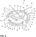
FIG. 6 is a side perspective view of a grate assembly including a heat shield, a grate, and a gasket configured as wall inserts, according to the present disclosure; -
FIG. 7 is a cross-sectional top plan view of engagements between a grate, a heat shield, and wall inserts, according to the present disclosure; -
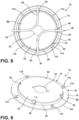
FIG. 8 is a top plan view of a grate assembly including a heat shield, a grate, and a gasket configured as a sealing insert, according to the present disclosure; -
FIG. 9 is a side perspective view of a heat shield with a sealing insert extending therethrough, according to the present disclosure; -
FIG. 10 is an exploded side perspective view of a heat shield and a sealing insert having a seal member and retention features, according to the present disclosure; -
FIG. 11 is a partial cross-sectional perspective view of a sealing insert extending through a heat shield to engage a base of a grate, according to the present disclosure; -
FIG. 12 is a side perspective view of a grate assembly including a heat shield, a grate, and a sealing insert, according to the present disclosure; -
FIG. 13 is a partial enlarged side perspective view of an engagement between a retention feature of a sealing insert and a base of a grate, according to the present disclosure; -
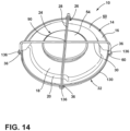
FIG. 14 is a side perspective view of a grate assembly including a heat shield, a grate, and a gasket configured as a border member, according to the present disclosure; -
FIG. 15 is a partial cross-sectional view of an outer edge of a heat shield positioned within a groove of a border member; and -
FIG. 16 is a partial side perspective view of a border member including a projection defining a recess, according to the present disclosure. - The components in the figures are not necessarily to scale, emphasis instead being placed upon illustrating the principles described herein.
- The present illustrated embodiments reside primarily in combinations of method steps and apparatus components related to a cooktop grate assembly. Accordingly, the apparatus components and method steps have been represented, where appropriate, by conventional symbols in the drawings, showing only those specific details that are pertinent to understanding the embodiments of the present disclosure so as not to obscure the disclosure with details that will be readily apparent to those of ordinary skill in the art having the benefit of the description herein. Further, like numerals in the description and drawings represent like elements.
- For purposes of description herein, the terms "upper," "lower," "right," "left," "rear," "front," "vertical," "horizontal," and derivatives thereof shall relate to the disclosure as oriented in
FIG. 1 . Unless stated otherwise, the term "front" shall refer to the surface of the element closer to an intended viewer, and the term "rear" shall refer to the surface of the element further from the intended viewer. However, it is to be understood that the disclosure may assume various alternative orientations, except where expressly specified to the contrary. It is also to be understood that the specific devices and processes illustrated in the attached drawings, and described in the following specification are simply exemplary embodiments of the inventive concepts defined in the appended claims. Hence, specific dimensions and other physical characteristics relating to the embodiments disclosed herein are not to be considered as limiting, unless the claims expressly state otherwise. - The terms "including," "comprises," "comprising," or any other variation thereof, are intended to cover a non-exclusive inclusion, such that a process, method, article, or apparatus that comprises a list of elements does not include only those elements but may include other elements not expressly listed or inherent to such process, method, article, or apparatus. An element preceded by "comprises a ... " does not, without more constraints, preclude the existence of additional identical elements in the process, method, article, or apparatus that comprises the element.
- With reference to
FIGS. 1-16 ,reference numeral 10 generally designates a grate assembly for acooktop 12 that includes aheat shield 14 having anouter rim 16 and acentral plateau region 18 offset from theouter rim 16 by a connectingwall 20. Thecentral plateau region 18 defines an opening 22 for receiving aburner assembly 24. Agrate 26 is positioned over theheat shield 14. Thegrate 26 includessupports central plateau region 18. Agasket 32 is disposed adjacent to theheat shield 14. Thegasket 32 engages at least one of abase 34 of thegrate 26 andfeet 36 of thesupports grate 26 in position relative to theheat shield 14. - Referring to
FIG. 1 , thecooktop 12 is illustrated as a standalone unit that includesmultiple burner assemblies 24. Eachburner assembly 24 is associated with anindividual grate assembly 10. Accordingly, eachcooktop 12 includesmultiple grate assemblies 10. Thecooktop 12 may be constructed of a ceramic, a glass ceramic, or a glass material. Thecooktop 12 may be included in a cooking appliance without departing from the teachings herein. - With reference to
FIGS. 1 and2 , eachgrate assembly 10 includes theheat shield 14, which is positioned on or adjacent to anupper surface 50 of thecooktop 12. Theheat shields 14 may deflect or diffuse heat generated by theburner assemblies 24. Theheat shields 14 may be advantageous for directing heat away from various components of thecooktop 12, including controls andelectronic components 52. Eachheat shield 14 includes theouter rim 16 disposed adjacent to theupper surface 50. Theouter rim 16 may be disposed on theupper surface 50 or on thegasket 32 depending on the configuration of thegasket 32. Eachheat shield 14 also includes thecentral plateau region 18, which defines theopening 22 for receiving theburner assembly 24. In certain aspects, theburner assembly 24 extends from thecooktop 12 and through theopening 22. Additionally or alternatively, aburner cap 54 of theburner assembly 24 may be positioned on or adjacent to anexterior surface 60 of thecentral plateau region 18 of theheat shield 14 under thesupports grate 26. - The
grates 26 are selectively positioned over therespective heat shields 14. In certain aspects, thegrates 26 include the base 34 configured to extend around thecentral plateau region 18. In the illustrated configuration ofFIG. 2 , thebase 34 of thegrate 26 is a ring that follows the shape of thecentral plateau region 18 and theoverall heat shield 14, which each defines a circular shape. Thebase 34 extends along theouter rim 16 adjacent to the connectingwall 20. The supports 28, 30 extend from thebase 34 and are configured to extend over thecentral plateau region 18. The supports 28, 30 are configured to support a cooking receptacle over theburner assembly 24. The supports 28, 30 each form or define an arcuate shape. There are twosupports supports opening 22. Accordingly, in certain aspects, thesupports - The
heat shield 14 generally definesindents 62 in whichfeet 36 of thesupports grate 26 at least partially extend. Thefeet 36 are generally disposed on or adjacent to theouter rim 16 of theheat shield 14 and partially within theindents 62 defined by theheat shield 14. Thefeet 36 of thesupports grate 26. Additionally, thefeet 36 may extend beyond anouter edge 64 of theheat shield 14 and onto or over theupper surface 50 of thecooktop 12. In various examples, theindents 62 provide a visual indicator for aligning thegrate 26 relative to theheat shield 14. Theindents 62 may also assist in retaining the position of thegrate 26 relative to theheat shield 14. - With reference still to
FIG. 2 , as well asFIGS. 3 and4 , eachgrate assembly 10 includes thegasket 32 configured to retain thegrate 26 in position relative to theheat shield 14. Thegasket 32 is configured to lock thegrate 26 in the selected position, thereby reducing movement of thegrate 26, which consequently stabilizes thegrate 26. As illustrated inFIGS. 2-4 , thegasket 32 is configured as a plurality of wall inserts 70, which are configured to extend through theheat shield 14 to engage thegrate 26. The illustratedgrate assembly 10 includes four wall inserts 70; however, any practicable number of wall inserts 70 may be utilized without departing from the teachings herein. - The connecting
wall 20 of theheat shield 14 definesapertures 72 spaced at intervals around theheat shield 14. Theapertures 72 may be positioned at substantially equal intervals about the connectingwall 20 or at any select locations. Eachwall insert 70 extends through one of therespective apertures 72 defined by the connectingwall 20. In this way, eachwall insert 70 is disposed at least partially under theheat shield 14 proximate to aninterior surface 74 of theheat shield 14 and partially outside of theheat shield 14 proximate to theexterior surface 60. - An
interior portion 76 of thewall insert 70 abuts theinterior surface 74 of the connectingwall 20, while anexterior portion 78 of thewall insert 70 abuts theexterior surface 60 of the connectingwall 20. Theinterior portion 76 and theexterior portion 78 are separated by a ledge or agroove 80. In examples with thegrooves 80, thegrooves 80 is configured to receive theheat shield 14 to retain the wall inserts 70 within theapertures 72 of the connectingwall 20. In examples with the ledge, the ledge may abut one of theexterior surface 60 and theinterior surface 74 of theheat shield 14 to prevent thewall insert 70 from moving further through theaperture 72. - Referring still to
FIGS. 2-4 , theexterior portion 78 protrudes from the connectingwall 20 to engage thegrate 26. Generally, thewall insert 70 engages aninner surface 82 of thebase 34. The wall inserts 70 extend between theheat shield 14 and thebase 34 of thegrate 26 to provide an interference or frictional engagement with thegrate 26, which is configured to retain thegrate 26 in position relative to theheat shield 14. As best illustrated inFIG. 3 , when thebase 34 is positioned on theouter rim 16, thebase 34 may engage the wall inserts 70 and also be positioned substantially below the wall inserts 70. In this configuration, thebase 34 has to move past a substantial portion of the wall inserts 70 to disengage from theheat shield 14, which provides greater stability and reduces movement of thegrate 26. - As illustrated in
FIGS. 3 and4 , theexterior portions 78 of the wall inserts 70 may form a substantially hemispherical shape. The rounded shape may be advantageous for coupling the wall inserts 70 with the connectingwall 20. Additionally, the rounded configuration of theexterior portion 78 may be advantageous for moving thegrate 26 past the wall inserts 70 and on theheat shield 14. For example, the rounded shape may provide less resistance when positioning thegrate 26 on theouter rim 16 of theheat shield 14. - Referring now to
FIG. 5 , an additional or alternative configuration of thewall insert 70 is illustrated. The illustratedwall insert 70 is elongated, having a more rectangular configuration. Theelongated wall insert 70 extends generally parallel with theouter rim 16 of theheat shield 14, which may provide an increased surface area for thegrate 26 to engage. The increased surface area may provide a greater interference or frictional engagement for retaining thegrate 26 in position relative to theheat shield 14. Eachgrate assembly 10 may include the more spherical wall inserts 70 illustrated inFIGS. 2-4 , the prism wall inserts 70 illustrated inFIG. 5 , or a combination thereof. - Referring to
FIGS. 6 and7 , an additional or alternative configuration of thegrate 26 is illustrated. Thegrate 26 includes the base 34 that is positioned on theouter rim 16 and extends along the connectingwall 20. The supports 28, 30 extend from thebase 34 and are configured to extend over thecentral plateau region 18. As illustrated inFIG. 6 , theburner cap 54 of theburner assembly 24 is positioned on or adjacent to theexterior surface 60 of thecentral plateau region 18 below anintersection point 90 of thesupports - The supports 28, 30 extend across to the
central plateau region 18 and couple with the base 34 on opposing sides of theburner assembly 24. The supports 28, 30 intersect with one another over theburner assembly 24. The supports 28, 30 each havefeet 36 that extend into theindents 62, over theouter rim 16, and onto theupper surface 50 of thecooktop 12. In various examples, thefeet 36 define astep 92, forming two different portions of a bottom 94 of thefeet 36. Thestep 92 allows a first portion of the bottom 94 of thefeet 36 to be positioned on theupper surface 50 of the cooktop 12 (FIG. 1 ) and the second portion to be positioned on theouter rim 16 of theheat shield 14. Thefeet 36 assist with aligning thegrate 26 relative to theheat shield 14, as well as stabilizing thegrate 26. - Referring to
FIGS. 2-7 , theindents 62 and theapertures 72 of theheat shield 14 generally alternate with one another. In the illustrated configurations, theheat shield 14 defines fourindents 62 and fourapertures 72. Eachaperture 72 is positioned between twoadjacent indents 62. Accordingly, thegrate 26 engages theheat shield 14 within theindents 62 and the wall inserts 70 engage thegrates 26 between thefeet 36. This configuration provides multiple engagement points between thegrate 26 and theheat shield 14, as well as multiple engagement points between thegrate 26 and the wall inserts 70 to increase the stability of thegrate 26. - The wall inserts 70 extend through the
heat shield 14 to engage thegrate 26 to retain thegrate 26 in position relative to theheat shield 14. Additionally, thewall insert 70 may be constructed of an elastically deformable material, such as rubber or silicone, to provide the interference or frictional engagement with thegrate 26. When thegrate 26 is disposed on theouter rim 16, the wall inserts 70 may be slightly deformed by thebase 34. The wall inserts 70 may apply a biasing force from the elastically deformable material toward thebase 34 of thegrate 26 when deformed, which assists in maintaining the engagement between the wall inserts 70 and thegrate 26. - In certain aspects, the wall inserts 70 may be constructed as spring-loaded pins. In such configurations, a spring may be disposed under the
heat shield 14 and the pins may extend through theapertures 72 to engage thegrate 26. The pins may be adjusted against a biasing force of the spring when engaged with thegrate 26. Additional or alternative configurations of the wall inserts 70 may be utilized in thegrate assembly 10 without departing from the teachings herein. - With reference now to
FIGS. 8-13 , an additional or alternative configuration of thegrate assembly 10 is illustrated. Theheat shield 14 includes thecentral plateau region 18 defining theopening 22 for theburner assembly 24. Theheat shield 14 also includes theouter rim 16 coupled to thecentral plateau region 18 via the connectingwall 20. Further, theheat shield 14 defines theindents 62 for receiving thefeet 36 of thegrate 26. In this configuration, the connectingwall 20 may be free of the apertures 72 (FIG. 3 ) while theouter rim 16 definesapertures 116 spaced about thecentral plateau region 18. In the illustrated configuration, theouter rim 16 defines fourapertures 116. - In the example illustrated in
FIGS. 8-13 , thegasket 32 is configured as a sealinginsert 110. The sealinginsert 110 includes aseal member 112 and retention features 114 extending from theseal member 112. Theseal member 112 is configured to be disposed below theouter rim 16 of theheat shield 14 adjacent to theinterior surface 74. Theheat shield 14 may be disposed at least partially on theseal member 112. Additionally or alternatively, theouter edge 64 of theheat shield 14 may curve to engage theupper surface 50 of the cooktop 12 (FIG. 1 ) adjacent to theseal member 112, which may be advantageous for concealing theseal member 112 below theheat shield 14. - The sealing
insert 110 provides theseal member 112 between theheat shield 14 and theupper surface 50 of the cooktop 12 (FIG. 1 ), which operates to minimize or prevent liquids and other food items from moving below theheat shield 14 or into an interior of the cooktop 12 (FIG. 1 ). Theseal member 112 extends adjacent to theouter edge 64 of theheat shield 14. Theheat shield 14 generally defines a geometric shape, which is a circle in the illustrated examples. Theseal member 112 defines a substantially similar or the same geometric shape as theheat shield 14, thereby forming a ring under theheat shield 14. The corresponding geometric shapes may be advantageous for providing the seal entirely around theheat shield 14. - Referring still to
FIGS. 8-13 , the sealinginsert 110 includes the retention features 114 extending from theseal member 112. The retention features 114 are spaced from one another and extend vertically from theseal member 112. In the illustrated configuration, four retention features 114 extend from theseal member 112, which corresponds with the number ofapertures 116 defined in theouter rim 16. It is contemplated that any number of retention features 114 andcorresponding apertures 116 may be utilized without departing the teachings herein. - As best illustrated in
FIG. 11 , theseal member 112 is disposed below theouter rim 16 adjacent to theouter edge 64 of theheat shield 14, and the retention features 114 extend through theapertures 116 to be disposed adjacent to theexterior surface 60 of theouter rim 16. The retention features 114 form protrusions extending vertically from theouter rim 16. The retention features 114 are generally U-shaped, with thebase 34 of thegrate 26 configured to be disposed in and retained by the U-shaped retention features 114. In various examples, at least thebase 34 of thegrate 26 may not directly contact theheat shield 14, but thebase 34 is supported by the retention features 114 spaced from theouter rim 16. In certain aspects, thebase 34 being supported on the retention features 114 may minimize or prevent direct contact between the remainder of thegrate 26 with theheat shield 14, thegrate 26 with theupper surface 50 of the cooktop 12 (FIG. 1 ), or a combination thereof. Reducing direct contact with theheat shield 14 may increase the longevity of thegrate assembly 10 and may also reduce heat transfer to thegrate 26. - The retention features 114 are generally elastically deformable, being constructed of, for example, rubber or silicone. The retention features 114 may be biased to form a smaller space than is utilized by the
base 34 of the grate 26 (e.g., smaller than the size of the base 34). In this way, positioning thebase 34 on the retention features 114 expands the retention features 114 and thereby forms an interference or frictional engagement between thegrate 26 and the sealinginsert 110. The retention features 114 may taper from aproximal end 118 coupled to theseal member 112 to adistal end 120, as best illustrated inFIGS. 10 and 11 . Alternatively, the retention features 114 may have the same width or thickness from theproximal end 118 to thedistal end 120, as best illustrated inFIGS. 12 and 13 , which may increase the surface area that engages with thebase 34 of thegrate 26. - The
grate 26 is positioned over theouter rim 16 and within each of the retention features 114. The retention features 114 operate to hold thegrate 26 in position relative to theheat shield 14. Additionally or alternatively, as theseal member 112 is disposed on opposing sides of theouter rim 16, the engagement between the retention features 114 and thegrate 26 may operate to couple thegrate 26 to theheat shield 14. - Referring again to
FIGS. 8-13 , thegrate assembly 10 includesmultiple engagement locations 96 between thegrate 26 and theheat shield 14 when thefeet 36 of thegrate 26 are at least partially within theindents 62. Further, thegrate assembly 10 includesmultiple engagement locations 98 between the sealinginsert 110 and thegrate 26. Theengagement locations 96 between thegrate 26 and theheat shield 14 alternate with theengagement locations 98 between thegrate 26 and the sealinginsert 110. In this way, eachretention feature 114 engages thebase 34 of thegrate 26 between twoadjacent feet 36 of thesupports engagement locations grate assembly 10. - Referring now to
FIGS. 14-16 , an additional or alternative configuration of thegrate assembly 10 is illustrated. Theheat shield 14 includes thecentral plateau region 18 defining the opening 22 (FIG. 2 ) for theburner assembly 24, theouter rim 16, and the connectingwall 20. In this configuration, the connectingwall 20 and theouter rim 16 have substantially continuous surfaces (e.g., are free of theapertures 72 as best illustrated inFIG. 3 and theapertures 116 as best illustrated inFIG. 10 ). Thecentral plateau region 18 may have a more oblong shape, having portions that extend closer to theouter edge 64 compared to other configurations of thegrate assembly 10 disclosed herein. - The
grate 26 is disposed over theburner assembly 24. In the illustrated configuration, thegrate 26 includes thesupports burner assembly 24. Thefeet 36 are positioned beyond theouter edge 64 of theheat shield 14. Further, in the illustrated configuration, theheat shield 14 is free of theindents 62 and thegrate 26 is free of the base 34 (FIG. 2 ). However, it is contemplated that theindents 62 in theheat shield 14 and thebase 34 of thegrate 26 may be included without departing from the teachings herein. In such examples, thefeet 36 may extend into theindents 62 of theheat shield 14, over theouter rim 16, and beyond theouter edge 64. Further, thebase 34 may extend around thecentral plateau region 18, having a more oblong shape to correspond with the shape of thecentral plateau region 18. - In the example illustrated in
FIGS. 14-16 , thegrate assembly 10 includes thegasket 32 configured as aborder member 130. Theborder member 130 is configured to extend along the perimeter of theheat shield 14. Theheat shield 14 defines the geometric shape, which is illustrated as a circular shape. Theborder member 130 defines a substantially similar or the same geometric shape, thereby forming a ring to extend along theouter edge 64 of theheat shield 14. - The
border member 130 is configured to be disposed on theupper surface 50 of the cooktop 12 (FIG. 1 ). Theborder member 130 defines agroove 132, which is generally anannular groove 132, that is configured to receive theouter edge 64 of theheat shield 14. Theouter edge 64 of theheat shield 14 defines a curve configured to be inserted into and retained in thegroove 132. Theborder member 130 is positioned between theupper surface 50 of thecooktop 12 and theheat shield 14, such that theheat shield 14 does not have direct contact with theupper surface 50. Theborder member 130 is configured to be disposed partially under theheat shield 14 adjacent to theinterior surface 74 and partially outside theheat shield 14 adjacent to theexterior surface 60. - As best illustrated in
FIG. 15 , a greater portion of theborder member 130 may be disposed under theheat shield 14 than outside of theheat shield 14 to conceal a greater portion of theborder member 130 from view. Theborder member 130 may define an uppercurved portion 134 that corresponds with the curve of theouter edge 64 of theheat shield 14. Theheat shield 14 may then be positioned on and follow the uppercurved portion 134 as theheat shield 14 extends into thegroove 132. The engagement between the uppercurved portion 134 and theheat shield 14 may assist in retaining theheat shield 14 in position relative to theborder member 130. For example, a frictional engagement can be formed between the uppercurved portion 134 of theborder member 130 and theouter rim 16 to reduce movement of theheat shield 14. - The
border member 130 is generally elastically deformable, being constructed of, for example, rubber or silicone. In certain aspects, thegroove 132 may be smaller in width than a thickness of theouter edge 64 of theheat shield 14. In this way, insertion of theheat shield 14 into thegroove 132 may slightly deform theborder member 130 and provide an interference or frictional fit between theborder member 130 and theouter edge 64 of theheat shield 14. Alternatively, thegroove 132 may be slightly wider in width or diameter than theouter edge 64, which may cause compression of theborder member 130 and a biasing force against theouter edge 64 to maintain the engagement between theheat shield 14 and theborder member 130. It is also contemplated thegroove 132 may have a slightly narrower width or diameter than theouter edge 64, causing an expansion of theborder member 130 when engaged with theheat shield 14. A biasing force from theborder member 130 due to the deformation, compression, or expansion may couple the retaining border to theheat shield 14. - Referring still to
FIGS. 14-16 , theborder member 130 forms a seal between theheat shield 14 and theupper surface 50 of thecooktop 12. Theborder member 130, generally configured as a ring, provides the seal along the perimeter of theheat shield 14. The configuration of theborder member 130 providing the seal may be advantageous for minimizing or preventing liquids and food items from moving below theheat shield 14 or into thecooktop 12. - The
border member 130 includes outwardly extendingprojections 136. When theborder member 130 is configured as the ring, theprojections 136 are generally radially extendingprojections 136. In the illustrated configuration, theborder member 130 includes fourprojections 136 spaced apart from one another along the perimeter of theheat shield 14. Theborder member 130 may include any practicable number ofprojections 136 and may include asmany projections 136 as the number offeet 36 included in thegrate 26. - The
projections 136 each define arecess 138, which are in fluid communication with thegroove 132 and may be outward extensions of thegroove 132. Thefeet 36 of thegrate 26 are configured to be positioned on theprojections 136, generally within therecesses 138. Theprojections 136 may be deformed as thefeet 36 are positioned within therecesses 138 to provide the interference or frictional engagement with thegrate 26. Additionally or alternatively, the material of theprojections 136 may also provide the interference or frictional engagement with the bottom 94 of thefeet 36. Theprojections 136 generally prevent direct contact between thegrate 26 and theupper surface 50 of thecooktop 12. The engagement between thegrate 26 and theprojections 136 also provides additional stability to thegrate 26 by reducing movement of thegrate 26 relative to theheat shield 14 and the cooktop 12 (FIG. 1 ). - Referring again to
FIGS. 1-16 , thecooktop 12 includesmultiple grate assemblies 10, which may have one or more of the configurations as described herein. Thegrate assembly 10 supports the cooking receptacle while proving increased stability to thegrate 26. Thegrates 26 and thegaskets 32 may have multiple configurations depending on the configuration of thecooktop 12. Thegasket 32 is configured to retain thegrate 26 in a selected position relative to theheat shield 14, which provides increased stability for thegrate 26 and reduces movement of thegrate 26. Additionally, certain configurations of theheat shield 14 are configured to provide the seal between theheat shield 14 and thecooktop 12. Additionally, thegaskets 32 may increase the efficiency of a manufacturing and assembly process. Eachgasket 32 may be constructed of an elastically deformable material to provide the interference or frictional engagement with theheat shield 14, thegrate 26, thecooktop 12, or a combination thereof. - Use of the present device may provide for a variety of advantages. For example, the
gasket 32 may provide the seal between theheat shield 14 and thecooktop 12. Additionally, thegasket 32 engaging theheat shield 14 may assist in retaining theheat shield 14 in a selected position relative to thecooktop 12. Further, thegasket 32 may provide the interference or frictional engagement with thegrate 26, which may retain thegrate 26 in the selected position relative to theheat shield 14. Additionally, thegasket 32 may be advantageous for providing additional stability to thegrate 26. Increased stability may be advantageous when thegrate 26 is supporting the cooking receptacle and a consumer is using thecooktop 12. Further, the interference or frictional engagement between thegasket 32 and theheat shield 14 and/or thegrate 26 may retain the selected components relative to one another during the assembly process, which may increase the efficiency of the manufacturing process. Additional benefits or advantages may be realized and/or achieved. - The device disclosed herein is further summarized in the following paragraphs and is further characterized by combinations of any and all of the various aspects described therein.
- According to an aspect of the present disclosure, a cooktop grate assembly includes a heat shield having an outer rim and a central plateau region offset from the outer rim by a connecting wall. The central plateau region defines an opening for receiving a burner assembly. A grate is positioned over the heat shield. The grate includes supports that extend over the central plateau region. A gasket is disposed adjacent to the heat shield. The gasket engages at least one of a base of the grate and feet of the supports to retain the grate in position relative to the heat shield.
- According to another aspect, a gasket is an insert that extends through an aperture defined in a connecting wall of a heat shield to engage a base of a grate when the base is positioned adjacent to an outer rim of the heat shield.
- According to another aspect, a gasket is a border member that defines a groove. An outer edge of a heat shield is disposed within the groove.
- According to another aspect, a border member includes outwardly extending projections. Feet of a grate are positioned on the outwardly extending projections.
- According to another aspect, a gasket is a sealing insert including a seal member and retention features extending from the seal member.
- According to another aspect, a seal member is disposed adjacent to an interior surface of an outer rim of a heat shield and retention features extend through apertures defined by the outer rim to engage a base of a grate.
- According to another aspect, retention features are U-shaped to receive a base of a grate.
- According to another aspect of the present disclosure, a grate assembly for a cooktop includes a heat shield with a central plateau region offset from an outer rim via a connecting wall. The heat shield has an interior surface oriented toward said cooktop and an exterior surface. A grate is selectively positioned over the heat shield. The grate includes a base disposed adjacent to the outer rim and supports extending from the base and over the central plateau region. A gasket is coupled to the heat shield. The gasket extends from proximate to the interior surface, through the heat shield, to proximate the exterior surface to engage the grate.
- According to another aspect, a gasket includes a seal member extending adjacent to an interior surface of an outer rim and adjacent to an outer edge of a heat shield.
- According to another aspect, an outer rim defines apertures. Retention features extend from a seal member and through the apertures to engage a base of a grate.
- According to another aspect, retention features are U-shaped for receiving a base of a grate. The base is spaced from an outer rim by the retention features.
- According to another aspect, a gasket includes a plurality of wall inserts. Each wall insert extends through an aperture defined by a connecting wall of a heat shield.
- According to another aspect, a plurality of wall inserts protrude from an exterior surface of a connecting wall to engage an inner surface of a base of a grate when the base is positioned adjacent to an outer rim of a heat shield.
- According to another aspect, each wall insert defines a groove configured to receive a heat shield to couple the wall inserts to the heat shield.
- According to another aspect, a heat shield defines indents, and feet of a grate are disposed within the indents.
- According to another aspect, a heat shield defines an aperture between adjacent indents. A gasket at least partially extends through each aperture.
- According to another aspect of the present disclosure, a grate assembly for a cooktop includes a heat shield with an outer rim and a central plateau region. The heat shield includes a curved outer edge. A grate is positioned over the heat shield. The grate includes supports and each support has feet selectively positioned adjacent to the outer rim. A gasket is disposed partially below the heat shield. The gasket defines a groove configured to receive the curved outer edge of the heat shield. The feet of the grate are positioned on projections of the gasket to retain the grate in position relative to the heat shield.
- According to another aspect, a gasket has an upper curved portion configured to abut an interior surface of an outer rim adjacent to an outer edge.
- According to another aspect, each projection defines a recess configured to receive feet, respectively.
- According to another aspect, a gasket is a border member forming a ring extending about a perimeter of the heat shield.
- For purposes of this disclosure, the term "coupled" (in all of its forms, couple, coupling, coupled, etc.) generally means the joining of two components (electrical or mechanical) directly or indirectly to one another. Such joining may be stationary in nature or movable in nature. Such joining may be achieved with the two components (electrical or mechanical) and any additional intermediate members being integrally formed as a single unitary body with one another or with the two components. Such joining may be permanent in nature or may be removable or releasable in nature unless otherwise stated.
Claims (15)
- A cooktop (12) grate assembly (10), comprising:a heat shield (14) having an outer rim (16) and a central plateau region (18) offset from the outer rim (16) by a connecting wall (20), wherein the central plateau region (18) defines an opening (22) for receiving a burner assembly (24);a grate (26) positioned over the heat shield (14), wherein the grate (26) includes supports (28, 30) that extend over the central plateau region (18); anda gasket (32, 70, 110, 130) disposed adjacent to the heat shield (14), wherein the gasket (32, 70, 110, 130) engages at least one of a base (34) of the grate (26) and feet (36) of the supports (28, 30) to retain the grate (26) in position relative to the heat shield (14).
- The cooktop (12) grate assembly (10) of claim 1, wherein the gasket (32, 130) is a border member (130) that defines a groove (132), and wherein an outer edge (64) of the heat shield (14) is disposed within the groove (132).
- The cooktop (12) grate assembly (10) of claim 2, wherein the border member (130) includes outwardly extending projections (136), and wherein the feet (36) of the grate (26) are positioned on the outwardly extending projections (136).
- The cooktop (12) grate assembly (10) of claim 3, wherein each projection (136) defines a recess (138) configured to receive the feet (36), respectively
- The cooktop (12) grate assembly (10) of any one of claims 2-4, wherein the border member (130) forms a ring extending about a perimeter of the heat shield (14).
- The cooktop (12) grate assembly (10) of claim 1, wherein the gasket (32, 70) extends from proximate to an interior surface (74) of the heat shield (14), through the heat shield (14), to proximate an exterior surface (60) of the heat shield (14) to engage the grate (26).
- The cooktop (12) grate assembly (10) of claim 6, wherein the gasket (32, 70) is at least one wall insert (70) configured to protrude from the exterior surface (60) of the connecting wall (20) to engage an inner surface (82) of the base (34) of the grate (26) when the base (34) is positioned adjacent to the outer rim (16) of the heat shield (14).
- The cooktop (12) grate assembly (10) of either of claim 6 or claim 7, and wherein the at least one wall insert (70) defines a groove (80) configured to receive the heat shield (14) to couple the at least one wall insert (70) to the heat shield (14).
- The cooktop (12) grate assembly (10) of either of any one of claims 6-8, wherein the gasket (32, 70, 110, 130) includes a plurality of wall inserts (70), and wherein each wall insert (70) extends through a respective aperture (72) defined by the connecting wall (20) of the heat shield (14).
- The cooktop (12) grate assembly (10) of either of claim 1, wherein the gasket (32, 110) is a sealing insert (110) including a seal member (112) and retention features (114) extending from the seal member (112).
- The cooktop (12) grate assembly (10) of claim 10, wherein the seal member (112) is disposed adjacent to an interior surface (74) of the outer rim (16) of the heat shield (14).
- The cooktop (12) grate assembly (10) of either of claim 10 or claim 11, and wherein the retention features (114) extend through apertures (116) defined by the outer rim (16) to engage the base (34) of the grate (26).
- The cooktop (12) grate assembly (10) of any one of claims 10-12, wherein the retention features (114) are U-shaped to receive the base (34) of the grate (26).
- The cooktop (12) grate assembly (10) of any one of claims 6-13, wherein the heat shield (14) defines indents (62), and wherein feet (36) of the grate (26) are disposed within the indents (62).
- The cooktop (12) grate assembly (10) of claim 14, wherein the heat shield (14) defines an aperture (72, 116) between adjacent indents (62), wherein the gasket (32, 70, 110) at least partially extends through each aperture (72, 116).
Applications Claiming Priority (1)
| Application Number | Priority Date | Filing Date | Title |
|---|---|---|---|
| US17/541,455 US11859829B2 (en) | 2021-12-03 | 2021-12-03 | Cooktop grate assembly |
Publications (1)
| Publication Number | Publication Date |
|---|---|
| EP4191145A1 true EP4191145A1 (en) | 2023-06-07 |
Family
ID=84369616
Family Applications (1)
| Application Number | Title | Priority Date | Filing Date |
|---|---|---|---|
| EP22210698.1A Withdrawn EP4191145A1 (en) | 2021-12-03 | 2022-11-30 | Cooktop grate assembly |
Country Status (2)
| Country | Link |
|---|---|
| US (1) | US11859829B2 (en) |
| EP (1) | EP4191145A1 (en) |
Citations (6)
| Publication number | Priority date | Publication date | Assignee | Title |
|---|---|---|---|---|
| US5046477A (en) * | 1990-12-28 | 1991-09-10 | Amana Refrigeration Inc. | Gas cook-top with glass top |
| US5628302A (en) * | 1995-06-21 | 1997-05-13 | Maytag Corporation | Burner assembly and pan seal |
| JPH10220782A (en) * | 1997-02-03 | 1998-08-21 | Rinnai Corp | Drop-in stove |
| DE20101865U1 (en) * | 2000-06-15 | 2001-06-07 | Schott Glas | Component of devices for food preparation and heating subject to high temperatures |
| KR20060134709A (en) * | 2005-06-23 | 2006-12-28 | 린나이코리아 주식회사 | Structure for grate packing of gas range |
| EP2998655B1 (en) * | 2014-09-18 | 2020-11-04 | E.G.O. Elektro-Gerätebau GmbH | Gas cooker |
Family Cites Families (15)
| Publication number | Priority date | Publication date | Assignee | Title |
|---|---|---|---|---|
| NL6708421A (en) | 1966-09-14 | 1968-03-15 | ||
| JPS5271040A (en) | 1975-12-08 | 1977-06-14 | Shimano Industrial Co | Device for driving bicycle |
| US4261327A (en) | 1979-04-06 | 1981-04-14 | Magic Chef, Inc. | Range grate and clip |
| US4593677A (en) | 1985-07-29 | 1986-06-10 | Magic Chef | Range grate and retaining clip assembly |
| US5372121A (en) | 1994-05-02 | 1994-12-13 | General Electric Company | Cooktop grate with improved stability |
| DE19905670A1 (en) | 1998-12-16 | 2000-09-07 | Schott Glas | Cooking utensil |
| US7410174B2 (en) | 2004-03-04 | 2008-08-12 | S & B Technical Products, Inc. | Restraining mechanical joint gasket for ductile iron pipe |
| US20090044795A1 (en) | 2007-08-17 | 2009-02-19 | Timothy Scott Shaffer | Grate apparatus and method of cleaning |
| US9612021B2 (en) | 2010-06-24 | 2017-04-04 | Bsh Home Appliances Corporation | Compressive stabilizing grate foot for home appliance |
| WO2014142130A1 (en) | 2013-03-13 | 2014-09-18 | パナソニックヘルスケア株式会社 | Cool box, control method for cool box, and control program for cool box |
| CN203815463U (en) | 2014-04-09 | 2014-09-10 | 沙福禄 | Low-temperature atomizing trace visualizing instrument |
| EP2942568B1 (en) | 2014-05-07 | 2017-11-08 | Electrolux Appliances Aktiebolag | Pot support with elastic foot and method for fixing elastic foot to a pot support |
| CN104075519A (en) | 2014-07-22 | 2014-10-01 | 合肥晶弘电器有限公司 | Refrigerator with warm-keeping chamber and temperature controlling method of warm-keeping chamber |
| KR101692626B1 (en) | 2015-06-22 | 2017-01-03 | 엘지전자 주식회사 | Gas cooker |
| US11149957B2 (en) | 2017-12-18 | 2021-10-19 | Hestan Commercial Corporation | Cooking vessel support grate |
-
2021
- 2021-12-03 US US17/541,455 patent/US11859829B2/en active Active
-
2022
- 2022-11-30 EP EP22210698.1A patent/EP4191145A1/en not_active Withdrawn
Patent Citations (6)
| Publication number | Priority date | Publication date | Assignee | Title |
|---|---|---|---|---|
| US5046477A (en) * | 1990-12-28 | 1991-09-10 | Amana Refrigeration Inc. | Gas cook-top with glass top |
| US5628302A (en) * | 1995-06-21 | 1997-05-13 | Maytag Corporation | Burner assembly and pan seal |
| JPH10220782A (en) * | 1997-02-03 | 1998-08-21 | Rinnai Corp | Drop-in stove |
| DE20101865U1 (en) * | 2000-06-15 | 2001-06-07 | Schott Glas | Component of devices for food preparation and heating subject to high temperatures |
| KR20060134709A (en) * | 2005-06-23 | 2006-12-28 | 린나이코리아 주식회사 | Structure for grate packing of gas range |
| EP2998655B1 (en) * | 2014-09-18 | 2020-11-04 | E.G.O. Elektro-Gerätebau GmbH | Gas cooker |
Also Published As
| Publication number | Publication date |
|---|---|
| US20230175703A1 (en) | 2023-06-08 |
| US11859829B2 (en) | 2024-01-02 |
Similar Documents
| Publication | Publication Date | Title |
|---|---|---|
| US6695319B1 (en) | Indexed sealing ring for pressure cooker, and pressure cooker equipped therewith | |
| US11692765B2 (en) | Appliance trim breaker assembly | |
| EP4191145A1 (en) | Cooktop grate assembly | |
| US5628302A (en) | Burner assembly and pan seal | |
| CN206354913U (en) | Steam valve and cooking apparatus | |
| CN109555858A (en) | Stopple | |
| EP4031466A1 (en) | Vacuum stopper and assembly of stopper and container | |
| US20240151604A1 (en) | Insulated structure for an appliance | |
| EP1196068B1 (en) | Liquid heating vessels | |
| EP0277098A2 (en) | Improved gasket of elastomer material in the form of a closed or open frame for cooking oven doors | |
| CN111491868B (en) | Sealable container system | |
| JP6719580B2 (en) | Male member of snap fastener and snap fastener | |
| US5814795A (en) | Nuxiliary cooking device for microwave ovens | |
| EP3663889B1 (en) | A sealing element for button-controlled cooking devices | |
| KR20190072241A (en) | Packing for electric rice cooker | |
| KR200488476Y1 (en) | Thermal insulation ring for gas range | |
| RU2806694C2 (en) | System for preparing beverage from capsule using liquid supplied under pressure into capsule and capsule for use in such system | |
| CN211673822U (en) | Cooking utensil and shell assembly thereof | |
| CN215892458U (en) | Cooking utensils | |
| CN215914150U (en) | Cooking utensil and pot body thereof | |
| CN211632795U (en) | Cooking utensil and pot lid thereof | |
| JP3156928U (en) | Transparent lid | |
| JP2006010281A (en) | Mounting structure of top plate for cooking stove | |
| USD1017402S1 (en) | Food bag seal clip | |
| CN210930858U (en) | Cooking utensil |
Legal Events
| Date | Code | Title | Description |
|---|---|---|---|
| PUAI | Public reference made under article 153(3) epc to a published international application that has entered the european phase |
Free format text: ORIGINAL CODE: 0009012 |
|
| STAA | Information on the status of an ep patent application or granted ep patent |
Free format text: STATUS: THE APPLICATION HAS BEEN PUBLISHED |
|
| AK | Designated contracting states |
Kind code of ref document: A1 Designated state(s): AL AT BE BG CH CY CZ DE DK EE ES FI FR GB GR HR HU IE IS IT LI LT LU LV MC ME MK MT NL NO PL PT RO RS SE SI SK SM TR |
|
| STAA | Information on the status of an ep patent application or granted ep patent |
Free format text: STATUS: THE APPLICATION HAS BEEN WITHDRAWN |
|
| 18W | Application withdrawn |
Effective date: 20231128 |