EP4191120A1 - Kryogen-speichersystem - Google Patents
Kryogen-speichersystem Download PDFInfo
- Publication number
- EP4191120A1 EP4191120A1 EP22210785.6A EP22210785A EP4191120A1 EP 4191120 A1 EP4191120 A1 EP 4191120A1 EP 22210785 A EP22210785 A EP 22210785A EP 4191120 A1 EP4191120 A1 EP 4191120A1
- Authority
- EP
- European Patent Office
- Prior art keywords
- extraction
- line
- heat exchanger
- consumer
- storage system
- Prior art date
- Legal status (The legal status is an assumption and is not a legal conclusion. Google has not performed a legal analysis and makes no representation as to the accuracy of the status listed.)
- Granted
Links
Images



Classifications
-
- F—MECHANICAL ENGINEERING; LIGHTING; HEATING; WEAPONS; BLASTING
- F17—STORING OR DISTRIBUTING GASES OR LIQUIDS
- F17C—VESSELS FOR CONTAINING OR STORING COMPRESSED, LIQUEFIED OR SOLIDIFIED GASES; FIXED-CAPACITY GAS-HOLDERS; FILLING VESSELS WITH, OR DISCHARGING FROM VESSELS, COMPRESSED, LIQUEFIED, OR SOLIDIFIED GASES
- F17C7/00—Methods or apparatus for discharging liquefied, solidified, or compressed gases from pressure vessels, not covered by another subclass
- F17C7/02—Discharging liquefied gases
- F17C7/04—Discharging liquefied gases with change of state, e.g. vaporisation
-
- F—MECHANICAL ENGINEERING; LIGHTING; HEATING; WEAPONS; BLASTING
- F17—STORING OR DISTRIBUTING GASES OR LIQUIDS
- F17C—VESSELS FOR CONTAINING OR STORING COMPRESSED, LIQUEFIED OR SOLIDIFIED GASES; FIXED-CAPACITY GAS-HOLDERS; FILLING VESSELS WITH, OR DISCHARGING FROM VESSELS, COMPRESSED, LIQUEFIED, OR SOLIDIFIED GASES
- F17C9/00—Methods or apparatus for discharging liquefied or solidified gases from vessels not under pressure
-
- F—MECHANICAL ENGINEERING; LIGHTING; HEATING; WEAPONS; BLASTING
- F17—STORING OR DISTRIBUTING GASES OR LIQUIDS
- F17C—VESSELS FOR CONTAINING OR STORING COMPRESSED, LIQUEFIED OR SOLIDIFIED GASES; FIXED-CAPACITY GAS-HOLDERS; FILLING VESSELS WITH, OR DISCHARGING FROM VESSELS, COMPRESSED, LIQUEFIED, OR SOLIDIFIED GASES
- F17C3/00—Vessels not under pressure
- F17C3/02—Vessels not under pressure with provision for thermal insulation
- F17C3/08—Vessels not under pressure with provision for thermal insulation by vacuum spaces, e.g. Dewar flask
-
- F—MECHANICAL ENGINEERING; LIGHTING; HEATING; WEAPONS; BLASTING
- F17—STORING OR DISTRIBUTING GASES OR LIQUIDS
- F17C—VESSELS FOR CONTAINING OR STORING COMPRESSED, LIQUEFIED OR SOLIDIFIED GASES; FIXED-CAPACITY GAS-HOLDERS; FILLING VESSELS WITH, OR DISCHARGING FROM VESSELS, COMPRESSED, LIQUEFIED, OR SOLIDIFIED GASES
- F17C13/00—Details of vessels or of the filling or discharging of vessels
-
- F—MECHANICAL ENGINEERING; LIGHTING; HEATING; WEAPONS; BLASTING
- F17—STORING OR DISTRIBUTING GASES OR LIQUIDS
- F17C—VESSELS FOR CONTAINING OR STORING COMPRESSED, LIQUEFIED OR SOLIDIFIED GASES; FIXED-CAPACITY GAS-HOLDERS; FILLING VESSELS WITH, OR DISCHARGING FROM VESSELS, COMPRESSED, LIQUEFIED, OR SOLIDIFIED GASES
- F17C13/00—Details of vessels or of the filling or discharging of vessels
- F17C13/04—Arrangement or mounting of valves
-
- F—MECHANICAL ENGINEERING; LIGHTING; HEATING; WEAPONS; BLASTING
- F17—STORING OR DISTRIBUTING GASES OR LIQUIDS
- F17C—VESSELS FOR CONTAINING OR STORING COMPRESSED, LIQUEFIED OR SOLIDIFIED GASES; FIXED-CAPACITY GAS-HOLDERS; FILLING VESSELS WITH, OR DISCHARGING FROM VESSELS, COMPRESSED, LIQUEFIED, OR SOLIDIFIED GASES
- F17C7/00—Methods or apparatus for discharging liquefied, solidified, or compressed gases from pressure vessels, not covered by another subclass
- F17C7/02—Discharging liquefied gases
-
- F—MECHANICAL ENGINEERING; LIGHTING; HEATING; WEAPONS; BLASTING
- F17—STORING OR DISTRIBUTING GASES OR LIQUIDS
- F17C—VESSELS FOR CONTAINING OR STORING COMPRESSED, LIQUEFIED OR SOLIDIFIED GASES; FIXED-CAPACITY GAS-HOLDERS; FILLING VESSELS WITH, OR DISCHARGING FROM VESSELS, COMPRESSED, LIQUEFIED, OR SOLIDIFIED GASES
- F17C2201/00—Vessel construction, in particular geometry, arrangement or size
- F17C2201/03—Orientation
- F17C2201/035—Orientation with substantially horizontal main axis
-
- F—MECHANICAL ENGINEERING; LIGHTING; HEATING; WEAPONS; BLASTING
- F17—STORING OR DISTRIBUTING GASES OR LIQUIDS
- F17C—VESSELS FOR CONTAINING OR STORING COMPRESSED, LIQUEFIED OR SOLIDIFIED GASES; FIXED-CAPACITY GAS-HOLDERS; FILLING VESSELS WITH, OR DISCHARGING FROM VESSELS, COMPRESSED, LIQUEFIED, OR SOLIDIFIED GASES
- F17C2201/00—Vessel construction, in particular geometry, arrangement or size
- F17C2201/05—Size
- F17C2201/054—Size medium (>1 m3)
-
- F—MECHANICAL ENGINEERING; LIGHTING; HEATING; WEAPONS; BLASTING
- F17—STORING OR DISTRIBUTING GASES OR LIQUIDS
- F17C—VESSELS FOR CONTAINING OR STORING COMPRESSED, LIQUEFIED OR SOLIDIFIED GASES; FIXED-CAPACITY GAS-HOLDERS; FILLING VESSELS WITH, OR DISCHARGING FROM VESSELS, COMPRESSED, LIQUEFIED, OR SOLIDIFIED GASES
- F17C2201/00—Vessel construction, in particular geometry, arrangement or size
- F17C2201/05—Size
- F17C2201/056—Small (<1 m3)
-
- F—MECHANICAL ENGINEERING; LIGHTING; HEATING; WEAPONS; BLASTING
- F17—STORING OR DISTRIBUTING GASES OR LIQUIDS
- F17C—VESSELS FOR CONTAINING OR STORING COMPRESSED, LIQUEFIED OR SOLIDIFIED GASES; FIXED-CAPACITY GAS-HOLDERS; FILLING VESSELS WITH, OR DISCHARGING FROM VESSELS, COMPRESSED, LIQUEFIED, OR SOLIDIFIED GASES
- F17C2203/00—Vessel construction, in particular walls or details thereof
- F17C2203/03—Thermal insulations
- F17C2203/0375—Thermal insulations by gas
- F17C2203/0379—Inert
-
- F—MECHANICAL ENGINEERING; LIGHTING; HEATING; WEAPONS; BLASTING
- F17—STORING OR DISTRIBUTING GASES OR LIQUIDS
- F17C—VESSELS FOR CONTAINING OR STORING COMPRESSED, LIQUEFIED OR SOLIDIFIED GASES; FIXED-CAPACITY GAS-HOLDERS; FILLING VESSELS WITH, OR DISCHARGING FROM VESSELS, COMPRESSED, LIQUEFIED, OR SOLIDIFIED GASES
- F17C2203/00—Vessel construction, in particular walls or details thereof
- F17C2203/03—Thermal insulations
- F17C2203/0391—Thermal insulations by vacuum
-
- F—MECHANICAL ENGINEERING; LIGHTING; HEATING; WEAPONS; BLASTING
- F17—STORING OR DISTRIBUTING GASES OR LIQUIDS
- F17C—VESSELS FOR CONTAINING OR STORING COMPRESSED, LIQUEFIED OR SOLIDIFIED GASES; FIXED-CAPACITY GAS-HOLDERS; FILLING VESSELS WITH, OR DISCHARGING FROM VESSELS, COMPRESSED, LIQUEFIED, OR SOLIDIFIED GASES
- F17C2203/00—Vessel construction, in particular walls or details thereof
- F17C2203/06—Materials for walls or layers thereof; Properties or structures of walls or their materials
- F17C2203/0602—Wall structures; Special features thereof
- F17C2203/0612—Wall structures
- F17C2203/0626—Multiple walls
- F17C2203/0629—Two walls
-
- F—MECHANICAL ENGINEERING; LIGHTING; HEATING; WEAPONS; BLASTING
- F17—STORING OR DISTRIBUTING GASES OR LIQUIDS
- F17C—VESSELS FOR CONTAINING OR STORING COMPRESSED, LIQUEFIED OR SOLIDIFIED GASES; FIXED-CAPACITY GAS-HOLDERS; FILLING VESSELS WITH, OR DISCHARGING FROM VESSELS, COMPRESSED, LIQUEFIED, OR SOLIDIFIED GASES
- F17C2205/00—Vessel construction, in particular mounting arrangements, attachments or identifications means
- F17C2205/03—Fluid connections, filters, valves, closure means or other attachments
- F17C2205/0302—Fittings, valves, filters, or components in connection with the gas storage device
- F17C2205/0323—Valves
-
- F—MECHANICAL ENGINEERING; LIGHTING; HEATING; WEAPONS; BLASTING
- F17—STORING OR DISTRIBUTING GASES OR LIQUIDS
- F17C—VESSELS FOR CONTAINING OR STORING COMPRESSED, LIQUEFIED OR SOLIDIFIED GASES; FIXED-CAPACITY GAS-HOLDERS; FILLING VESSELS WITH, OR DISCHARGING FROM VESSELS, COMPRESSED, LIQUEFIED, OR SOLIDIFIED GASES
- F17C2205/00—Vessel construction, in particular mounting arrangements, attachments or identifications means
- F17C2205/03—Fluid connections, filters, valves, closure means or other attachments
- F17C2205/0302—Fittings, valves, filters, or components in connection with the gas storage device
- F17C2205/0323—Valves
- F17C2205/0326—Valves electrically actuated
-
- F—MECHANICAL ENGINEERING; LIGHTING; HEATING; WEAPONS; BLASTING
- F17—STORING OR DISTRIBUTING GASES OR LIQUIDS
- F17C—VESSELS FOR CONTAINING OR STORING COMPRESSED, LIQUEFIED OR SOLIDIFIED GASES; FIXED-CAPACITY GAS-HOLDERS; FILLING VESSELS WITH, OR DISCHARGING FROM VESSELS, COMPRESSED, LIQUEFIED, OR SOLIDIFIED GASES
- F17C2205/00—Vessel construction, in particular mounting arrangements, attachments or identifications means
- F17C2205/03—Fluid connections, filters, valves, closure means or other attachments
- F17C2205/0302—Fittings, valves, filters, or components in connection with the gas storage device
- F17C2205/0352—Pipes
-
- F—MECHANICAL ENGINEERING; LIGHTING; HEATING; WEAPONS; BLASTING
- F17—STORING OR DISTRIBUTING GASES OR LIQUIDS
- F17C—VESSELS FOR CONTAINING OR STORING COMPRESSED, LIQUEFIED OR SOLIDIFIED GASES; FIXED-CAPACITY GAS-HOLDERS; FILLING VESSELS WITH, OR DISCHARGING FROM VESSELS, COMPRESSED, LIQUEFIED, OR SOLIDIFIED GASES
- F17C2205/00—Vessel construction, in particular mounting arrangements, attachments or identifications means
- F17C2205/03—Fluid connections, filters, valves, closure means or other attachments
- F17C2205/0302—Fittings, valves, filters, or components in connection with the gas storage device
- F17C2205/0352—Pipes
- F17C2205/0367—Arrangements in parallel
-
- F—MECHANICAL ENGINEERING; LIGHTING; HEATING; WEAPONS; BLASTING
- F17—STORING OR DISTRIBUTING GASES OR LIQUIDS
- F17C—VESSELS FOR CONTAINING OR STORING COMPRESSED, LIQUEFIED OR SOLIDIFIED GASES; FIXED-CAPACITY GAS-HOLDERS; FILLING VESSELS WITH, OR DISCHARGING FROM VESSELS, COMPRESSED, LIQUEFIED, OR SOLIDIFIED GASES
- F17C2205/00—Vessel construction, in particular mounting arrangements, attachments or identifications means
- F17C2205/03—Fluid connections, filters, valves, closure means or other attachments
- F17C2205/0388—Arrangement of valves, regulators, filters
-
- F—MECHANICAL ENGINEERING; LIGHTING; HEATING; WEAPONS; BLASTING
- F17—STORING OR DISTRIBUTING GASES OR LIQUIDS
- F17C—VESSELS FOR CONTAINING OR STORING COMPRESSED, LIQUEFIED OR SOLIDIFIED GASES; FIXED-CAPACITY GAS-HOLDERS; FILLING VESSELS WITH, OR DISCHARGING FROM VESSELS, COMPRESSED, LIQUEFIED, OR SOLIDIFIED GASES
- F17C2205/00—Vessel construction, in particular mounting arrangements, attachments or identifications means
- F17C2205/03—Fluid connections, filters, valves, closure means or other attachments
- F17C2205/0388—Arrangement of valves, regulators, filters
- F17C2205/0391—Arrangement of valves, regulators, filters inside the pressure vessel
-
- F—MECHANICAL ENGINEERING; LIGHTING; HEATING; WEAPONS; BLASTING
- F17—STORING OR DISTRIBUTING GASES OR LIQUIDS
- F17C—VESSELS FOR CONTAINING OR STORING COMPRESSED, LIQUEFIED OR SOLIDIFIED GASES; FIXED-CAPACITY GAS-HOLDERS; FILLING VESSELS WITH, OR DISCHARGING FROM VESSELS, COMPRESSED, LIQUEFIED, OR SOLIDIFIED GASES
- F17C2221/00—Handled fluid, in particular type of fluid
- F17C2221/01—Pure fluids
- F17C2221/012—Hydrogen
-
- F—MECHANICAL ENGINEERING; LIGHTING; HEATING; WEAPONS; BLASTING
- F17—STORING OR DISTRIBUTING GASES OR LIQUIDS
- F17C—VESSELS FOR CONTAINING OR STORING COMPRESSED, LIQUEFIED OR SOLIDIFIED GASES; FIXED-CAPACITY GAS-HOLDERS; FILLING VESSELS WITH, OR DISCHARGING FROM VESSELS, COMPRESSED, LIQUEFIED, OR SOLIDIFIED GASES
- F17C2223/00—Handled fluid before transfer, i.e. state of fluid when stored in the vessel or before transfer from the vessel
- F17C2223/01—Handled fluid before transfer, i.e. state of fluid when stored in the vessel or before transfer from the vessel characterised by the phase
- F17C2223/0146—Two-phase
- F17C2223/0153—Liquefied gas, e.g. LPG, GPL
- F17C2223/0161—Liquefied gas, e.g. LPG, GPL cryogenic, e.g. LNG, GNL, PLNG
-
- F—MECHANICAL ENGINEERING; LIGHTING; HEATING; WEAPONS; BLASTING
- F17—STORING OR DISTRIBUTING GASES OR LIQUIDS
- F17C—VESSELS FOR CONTAINING OR STORING COMPRESSED, LIQUEFIED OR SOLIDIFIED GASES; FIXED-CAPACITY GAS-HOLDERS; FILLING VESSELS WITH, OR DISCHARGING FROM VESSELS, COMPRESSED, LIQUEFIED, OR SOLIDIFIED GASES
- F17C2223/00—Handled fluid before transfer, i.e. state of fluid when stored in the vessel or before transfer from the vessel
- F17C2223/01—Handled fluid before transfer, i.e. state of fluid when stored in the vessel or before transfer from the vessel characterised by the phase
- F17C2223/0146—Two-phase
- F17C2223/0153—Liquefied gas, e.g. LPG, GPL
- F17C2223/0169—Liquefied gas, e.g. LPG, GPL subcooled
-
- F—MECHANICAL ENGINEERING; LIGHTING; HEATING; WEAPONS; BLASTING
- F17—STORING OR DISTRIBUTING GASES OR LIQUIDS
- F17C—VESSELS FOR CONTAINING OR STORING COMPRESSED, LIQUEFIED OR SOLIDIFIED GASES; FIXED-CAPACITY GAS-HOLDERS; FILLING VESSELS WITH, OR DISCHARGING FROM VESSELS, COMPRESSED, LIQUEFIED, OR SOLIDIFIED GASES
- F17C2223/00—Handled fluid before transfer, i.e. state of fluid when stored in the vessel or before transfer from the vessel
- F17C2223/04—Handled fluid before transfer, i.e. state of fluid when stored in the vessel or before transfer from the vessel characterised by other properties of handled fluid before transfer
- F17C2223/042—Localisation of the removal point
- F17C2223/043—Localisation of the removal point in the gas
-
- F—MECHANICAL ENGINEERING; LIGHTING; HEATING; WEAPONS; BLASTING
- F17—STORING OR DISTRIBUTING GASES OR LIQUIDS
- F17C—VESSELS FOR CONTAINING OR STORING COMPRESSED, LIQUEFIED OR SOLIDIFIED GASES; FIXED-CAPACITY GAS-HOLDERS; FILLING VESSELS WITH, OR DISCHARGING FROM VESSELS, COMPRESSED, LIQUEFIED, OR SOLIDIFIED GASES
- F17C2223/00—Handled fluid before transfer, i.e. state of fluid when stored in the vessel or before transfer from the vessel
- F17C2223/04—Handled fluid before transfer, i.e. state of fluid when stored in the vessel or before transfer from the vessel characterised by other properties of handled fluid before transfer
- F17C2223/042—Localisation of the removal point
- F17C2223/046—Localisation of the removal point in the liquid
- F17C2223/047—Localisation of the removal point in the liquid with a dip tube
-
- F—MECHANICAL ENGINEERING; LIGHTING; HEATING; WEAPONS; BLASTING
- F17—STORING OR DISTRIBUTING GASES OR LIQUIDS
- F17C—VESSELS FOR CONTAINING OR STORING COMPRESSED, LIQUEFIED OR SOLIDIFIED GASES; FIXED-CAPACITY GAS-HOLDERS; FILLING VESSELS WITH, OR DISCHARGING FROM VESSELS, COMPRESSED, LIQUEFIED, OR SOLIDIFIED GASES
- F17C2227/00—Transfer of fluids, i.e. method or means for transferring the fluid; Heat exchange with the fluid
- F17C2227/03—Heat exchange with the fluid
- F17C2227/0302—Heat exchange with the fluid by heating
-
- F—MECHANICAL ENGINEERING; LIGHTING; HEATING; WEAPONS; BLASTING
- F17—STORING OR DISTRIBUTING GASES OR LIQUIDS
- F17C—VESSELS FOR CONTAINING OR STORING COMPRESSED, LIQUEFIED OR SOLIDIFIED GASES; FIXED-CAPACITY GAS-HOLDERS; FILLING VESSELS WITH, OR DISCHARGING FROM VESSELS, COMPRESSED, LIQUEFIED, OR SOLIDIFIED GASES
- F17C2227/00—Transfer of fluids, i.e. method or means for transferring the fluid; Heat exchange with the fluid
- F17C2227/03—Heat exchange with the fluid
- F17C2227/0302—Heat exchange with the fluid by heating
- F17C2227/0309—Heat exchange with the fluid by heating using another fluid
-
- F—MECHANICAL ENGINEERING; LIGHTING; HEATING; WEAPONS; BLASTING
- F17—STORING OR DISTRIBUTING GASES OR LIQUIDS
- F17C—VESSELS FOR CONTAINING OR STORING COMPRESSED, LIQUEFIED OR SOLIDIFIED GASES; FIXED-CAPACITY GAS-HOLDERS; FILLING VESSELS WITH, OR DISCHARGING FROM VESSELS, COMPRESSED, LIQUEFIED, OR SOLIDIFIED GASES
- F17C2227/00—Transfer of fluids, i.e. method or means for transferring the fluid; Heat exchange with the fluid
- F17C2227/03—Heat exchange with the fluid
- F17C2227/0337—Heat exchange with the fluid by cooling
- F17C2227/0339—Heat exchange with the fluid by cooling using the same fluid
-
- F—MECHANICAL ENGINEERING; LIGHTING; HEATING; WEAPONS; BLASTING
- F17—STORING OR DISTRIBUTING GASES OR LIQUIDS
- F17C—VESSELS FOR CONTAINING OR STORING COMPRESSED, LIQUEFIED OR SOLIDIFIED GASES; FIXED-CAPACITY GAS-HOLDERS; FILLING VESSELS WITH, OR DISCHARGING FROM VESSELS, COMPRESSED, LIQUEFIED, OR SOLIDIFIED GASES
- F17C2227/00—Transfer of fluids, i.e. method or means for transferring the fluid; Heat exchange with the fluid
- F17C2227/03—Heat exchange with the fluid
- F17C2227/0367—Localisation of heat exchange
- F17C2227/0369—Localisation of heat exchange in or on a vessel
- F17C2227/0374—Localisation of heat exchange in or on a vessel in the liquid
-
- F—MECHANICAL ENGINEERING; LIGHTING; HEATING; WEAPONS; BLASTING
- F17—STORING OR DISTRIBUTING GASES OR LIQUIDS
- F17C—VESSELS FOR CONTAINING OR STORING COMPRESSED, LIQUEFIED OR SOLIDIFIED GASES; FIXED-CAPACITY GAS-HOLDERS; FILLING VESSELS WITH, OR DISCHARGING FROM VESSELS, COMPRESSED, LIQUEFIED, OR SOLIDIFIED GASES
- F17C2227/00—Transfer of fluids, i.e. method or means for transferring the fluid; Heat exchange with the fluid
- F17C2227/03—Heat exchange with the fluid
- F17C2227/0367—Localisation of heat exchange
- F17C2227/0369—Localisation of heat exchange in or on a vessel
- F17C2227/0376—Localisation of heat exchange in or on a vessel in wall contact
- F17C2227/0381—Localisation of heat exchange in or on a vessel in wall contact integrated in the wall
-
- F—MECHANICAL ENGINEERING; LIGHTING; HEATING; WEAPONS; BLASTING
- F17—STORING OR DISTRIBUTING GASES OR LIQUIDS
- F17C—VESSELS FOR CONTAINING OR STORING COMPRESSED, LIQUEFIED OR SOLIDIFIED GASES; FIXED-CAPACITY GAS-HOLDERS; FILLING VESSELS WITH, OR DISCHARGING FROM VESSELS, COMPRESSED, LIQUEFIED, OR SOLIDIFIED GASES
- F17C2265/00—Effects achieved by gas storage or gas handling
- F17C2265/06—Fluid distribution
- F17C2265/066—Fluid distribution for feeding engines for propulsion
-
- F—MECHANICAL ENGINEERING; LIGHTING; HEATING; WEAPONS; BLASTING
- F17—STORING OR DISTRIBUTING GASES OR LIQUIDS
- F17C—VESSELS FOR CONTAINING OR STORING COMPRESSED, LIQUEFIED OR SOLIDIFIED GASES; FIXED-CAPACITY GAS-HOLDERS; FILLING VESSELS WITH, OR DISCHARGING FROM VESSELS, COMPRESSED, LIQUEFIED, OR SOLIDIFIED GASES
- F17C2270/00—Applications
- F17C2270/01—Applications for fluid transport or storage
- F17C2270/0102—Applications for fluid transport or storage on or in the water
- F17C2270/0105—Ships
-
- F—MECHANICAL ENGINEERING; LIGHTING; HEATING; WEAPONS; BLASTING
- F17—STORING OR DISTRIBUTING GASES OR LIQUIDS
- F17C—VESSELS FOR CONTAINING OR STORING COMPRESSED, LIQUEFIED OR SOLIDIFIED GASES; FIXED-CAPACITY GAS-HOLDERS; FILLING VESSELS WITH, OR DISCHARGING FROM VESSELS, COMPRESSED, LIQUEFIED, OR SOLIDIFIED GASES
- F17C2270/00—Applications
- F17C2270/01—Applications for fluid transport or storage
- F17C2270/0165—Applications for fluid transport or storage on the road
- F17C2270/0168—Applications for fluid transport or storage on the road by vehicles
-
- F—MECHANICAL ENGINEERING; LIGHTING; HEATING; WEAPONS; BLASTING
- F17—STORING OR DISTRIBUTING GASES OR LIQUIDS
- F17C—VESSELS FOR CONTAINING OR STORING COMPRESSED, LIQUEFIED OR SOLIDIFIED GASES; FIXED-CAPACITY GAS-HOLDERS; FILLING VESSELS WITH, OR DISCHARGING FROM VESSELS, COMPRESSED, LIQUEFIED, OR SOLIDIFIED GASES
- F17C2270/00—Applications
- F17C2270/01—Applications for fluid transport or storage
- F17C2270/0165—Applications for fluid transport or storage on the road
- F17C2270/0184—Fuel cells
-
- F—MECHANICAL ENGINEERING; LIGHTING; HEATING; WEAPONS; BLASTING
- F17—STORING OR DISTRIBUTING GASES OR LIQUIDS
- F17C—VESSELS FOR CONTAINING OR STORING COMPRESSED, LIQUEFIED OR SOLIDIFIED GASES; FIXED-CAPACITY GAS-HOLDERS; FILLING VESSELS WITH, OR DISCHARGING FROM VESSELS, COMPRESSED, LIQUEFIED, OR SOLIDIFIED GASES
- F17C2270/00—Applications
- F17C2270/01—Applications for fluid transport or storage
- F17C2270/0186—Applications for fluid transport or storage in the air or in space
- F17C2270/0189—Planes
-
- F—MECHANICAL ENGINEERING; LIGHTING; HEATING; WEAPONS; BLASTING
- F17—STORING OR DISTRIBUTING GASES OR LIQUIDS
- F17C—VESSELS FOR CONTAINING OR STORING COMPRESSED, LIQUEFIED OR SOLIDIFIED GASES; FIXED-CAPACITY GAS-HOLDERS; FILLING VESSELS WITH, OR DISCHARGING FROM VESSELS, COMPRESSED, LIQUEFIED, OR SOLIDIFIED GASES
- F17C2270/00—Applications
- F17C2270/01—Applications for fluid transport or storage
- F17C2270/0186—Applications for fluid transport or storage in the air or in space
- F17C2270/0197—Rockets
-
- Y—GENERAL TAGGING OF NEW TECHNOLOGICAL DEVELOPMENTS; GENERAL TAGGING OF CROSS-SECTIONAL TECHNOLOGIES SPANNING OVER SEVERAL SECTIONS OF THE IPC; TECHNICAL SUBJECTS COVERED BY FORMER USPC CROSS-REFERENCE ART COLLECTIONS [XRACs] AND DIGESTS
- Y02—TECHNOLOGIES OR APPLICATIONS FOR MITIGATION OR ADAPTATION AGAINST CLIMATE CHANGE
- Y02E—REDUCTION OF GREENHOUSE GAS [GHG] EMISSIONS, RELATED TO ENERGY GENERATION, TRANSMISSION OR DISTRIBUTION
- Y02E60/00—Enabling technologies; Technologies with a potential or indirect contribution to GHG emissions mitigation
- Y02E60/30—Hydrogen technology
- Y02E60/32—Hydrogen storage
Definitions
- the present invention relates to a storage system for storing a cryogenic medium, in particular for storing hydrogen.
- the invention also relates to a device comprising such a storage system and a consumer for the medium accommodated in the storage container of the storage system.
- cryogenic media ie cryogenic and at least partially liquid media such as hydrogen or helium
- the medium is usually partly in liquid form in the storage container and partly also in gaseous form.
- cryogenic storage systems In known cryogenic storage systems, a wide variety of lines are arranged as a connection between the inner tank and the external environment of the storage system. These are required for various purposes, such as conducting cryogenic liquid medium from the inner tank to the heat exchanger or evaporator to a consumer. Sometimes such storage systems also have a pressure build-up system, depending on the type, an open or closed system. A pressure build-up system can compensate for the pressure drop that occurs when hydrogen, for example, is removed in gaseous or liquid form. This is usually done either by an in-tank heat exchanger (closed pipe system) or by direct evaporation (open system).
- a storage system for storing a cryogenic medium, in particular for storing hydrogen comprising a storage container for receiving the medium, with a first extraction line forming a fluid-conducting connection from the interior of the storage container to a consumer connection, for connecting a consumer , wherein at least a first controllable line shut-off valve and a first heat exchanger are arranged in the first extraction branch, wherein a second extraction branch, which is different from the first extraction branch, has a fluid-conducting connection from the interior of the storage container to a consumer connection, for Connection of the same consumer forms, with at least one second controllable line shut-off valve and a further first heat exchanger being arranged in the second extraction line.
- the extraction branch of a storage system comprises a controllable line shut-off valve to control the extraction of the medium from the storage container into the extraction branch and downstream of this line shut-off valve a first heat exchanger, which serves to temper the extracted medium, in particular hydrogen, to the desired extraction conditions , in particular to heat up and possibly, if liquid medium was removed, also to evaporate.
- a withdrawal line from the inner container to a consumer, is designed redundantly twice—or more often. Therefore, according to the invention, there is a first removal line and a different second removal line, each of the removal lines having components of the same type, so that the removal lines can perform the same function.
- both the first and the second sampling line have an associated line shut-off valve to control the inflow into the sampling line, and an associated heat exchanger to temper the medium to the desired sampling conditions.
- first and second withdrawal line can both be set up to withdraw gaseous medium from the storage container or both be set up to withdraw liquid medium from the storage container.
- first removal line can also be set up to remove gaseous medium from the storage container and the second removal line can be set up to remove liquid medium from the storage container.
- the consumer connection of the first extraction branch and the consumer connection of the second extraction branch are brought together to form a common connection.
- the two consumer connections are not combined to form a common connection. The two consumer connections can thus form a common connection or two separate connections on the same consumer.
- the first extraction branch also has a third controllable line shut-off valve directly in front of the consumer connection and the second extraction branch also has a further third controllable line shut-off valve directly in front of the consumer connection.
- the third controllable line shut-off valve can serve as a shut-off device in front of the connected consumer.
- the first bleed line preferably additionally has an inner-tank heat exchanger downstream of the first heat exchanger, and the second bleed line also has a further inner-tank heat exchanger after the further first heat exchanger.
- the in-tank heat exchanger in each extraction leg serves to control or regulate the pressure inside the storage tank using the heated extraction medium.
- the first extraction branch additionally has a second heat exchanger after the inner-tank heat exchanger and the second extraction branch additionally has a further second heat exchanger after the further inner-tank heat exchanger.
- the second heat exchanger makes it possible to ensure compliance with the desired removal conditions for the medium even after the heat has been transferred through the inner-tank heat exchanger of the respective removal line.
- the first bleed line also has a partial flow control valve after the first controllable line shut-off valve and before the inner-tank heat exchanger
- the second bleed line also has a further partial-flow control valve after the second controllable line shut-off valve and before the other inner-tank heat exchanger. Via the partial flow control valves, only part of the extracted and heated medium can be returned to the storage tank, to the respective inner tank heat exchanger.
- all components of the first extraction line up to the consumer connection can also be redundantly present in the second extraction line and arranged in the same order.
- the storage tank is double-walled, with an insulating vacuum space between the two walls of the storage tank.
- the first and second controllable line shut-off valve and/or the two first heat exchangers of the first and second bleed line are arranged in the vacuum space, particularly preferably also the second heat exchangers of the first and second bleed line.
- the first and second controllable line shut-off valve and/or the first heat exchangers of the first and second extraction line are arranged outside an outer tank of the storage tank, with at least parts of lines outside an outer tank of the storage tank being designed as vacuum-insulated lines.
- the storage tank can also comprise at least one secondary vacuum space or space with an inert gas atmosphere - in particular in addition to a vacuum space between the inner and outer wall of the tank -, the first and second controllable line shut-off valve and/or the first heat exchangers of the first and second extraction line - and preferably all components of the first and second extraction line - are arranged in the secondary vacuum space or space with an inert gas atmosphere.
- the components for the first and second sampling line are each arranged in a separate secondary vacuum area or space with an inert gas atmosphere, i.e. assigned to the first or second sampling line, so that each sampling line has its own secondary vacuum space or space with an inert gas atmosphere.
- the object is also achieved by a device comprising a storage system, as described above, and a consumer for the medium accommodated in the storage container, the consumer connection of the first extraction line and the consumer connection of the second extraction line being connected to the consumer.
- the consumer connection of the first extraction line and the consumer connection of the second extraction line can be merged into a common connection on the consumer or instead not merged into a common connection on the consumer, ie form two separate connections on the consumer.
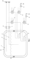
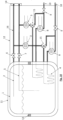
- the storage system includes a storage container 1 for receiving the medium.
- the storage container 1 forms an inner container of a double-walled container which additionally comprises an outer container 11 .
- a vacuum is formed between the outer container 11 and the inner container, ie storage container 1 .
- Suspensions 13 are also arranged in sections between the outer container 11 and the inner container in order to position the two shells of the double-walled container in relation to one another.
- the cryogenic medium in particular hydrogen, is located in the lower area of the storage container 1, namely below the liquid surface shown as a wavy line in the figure as a liquid in the container, above the wavy liquid surface in a gaseous state.
- a gas extraction line 2 is set up to extract the gaseous medium from the storage tank 1 so that the free end of the gas extraction line 2 ends in the storage tank 1 above the liquid surface, near the top of the storage tank 1 .
- the first sampling branch begins.
- a liquid extraction line 5 is arranged for extraction of the liquid medium from the storage tank 1, so that the free end of the liquid extraction line 5 is below the liquid surface, in the vicinity the bottom of the storage container 1, in the storage container 1 ends. With the liquid extraction line 5, the second extraction line begins.
- bottom refer to the usual installation position of the storage container, for example in a traveling, floating or flying transport device, with gravity acting in normal operation of the transport device towards the bottom of the storage container.
- a first controllable line shut-off valve 6 is arranged in the gas extraction line 2 and a second controllable line shut-off valve 7 is arranged in the liquid extraction line 5 .
- Both line shut-off valves are located outside of storage tank 1. In the 1 the line shut-off valves are also located outside of the outer tank 11.
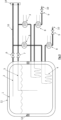
- the in 2 is shown, the two line shut-off valves 6, 7 are arranged inside the outer container 11, ie between the inner container, storage container 1, and the outer container 11 of the double-walled storage container, namely in the vacuum space.
- the line shut-off valves are controlled by a control device also located in the vacuum space ( Fig.2 ) or outside the entire container ( 1 ) can be arranged, controllable.
- the flow through the line shut-off valves can preferably not only be interrupted or released, but also reduced.
- the storage container 1 can also be refueled from a refueling device 14.
- the gas extraction line 2 and the liquid extraction line 5 also run after the two line shut-off valves 6, 7 as two separate lines, each with their own associated components, and therefore form two separate extraction lines.
- the gas extraction line 2 and the liquid extraction line 5 are separate extraction branches with the associated outside of the storage tank 1, for example between the storage tank 1 and the outer tank 11 of the double-walled storage tank ( 2 ), Arranged, flow-connected first heat exchanger 3 for heating the sampled medium.
- An inner-tank heat exchanger 4 for heating the liquid medium in the storage container 1 is arranged downstream of the first heat exchanger 3 within the storage container 1 , through which the heated medium removed from the storage container 1 flows.
- the liquid medium in the storage container 1 is partially heated and evaporated by the heating at the inner tank heat exchanger 4 .
- a second heat exchanger 8 for heating the medium is arranged in the first extraction line and in the second extraction line.
- the medium flowing through the first and/or second extraction branch is fed downstream of the respective inner-tank heat exchanger 4 to the same consumer via a respective consumer connection 10, in particular a fuel cell as consumer.
- a third line shut-off valve 9 is arranged between the second heat exchanger 8 and the consumer 10 in each extraction line.
- the embodiment of 2 differs from that 1 that control-relevant components of both extraction lines of the storage system, such as the first heat exchanger 3, the second heat exchanger 8, the first line shut-off valve 6 and the second line shut-off valve 8, are arranged inside the outer tank 11, not outside the outer tank 11 as in 1 , and are thus arranged in the intermediate space of the double-walled container, which forms a vacuum space.
- control-relevant components of both extraction lines of the storage system such as the first heat exchanger 3, the second heat exchanger 8, the first line shut-off valve 6 and the second line shut-off valve 8 are arranged inside the outer tank 11, not outside the outer tank 11 as in 1 , and are thus arranged in the intermediate space of the double-walled container, which forms a vacuum space.
- Two separate areas of the vacuum space can be used exclusively for the heat exchangers 3, 8 of the first extraction branch and for the heat exchangers 3, 8 of the second extraction branch. As a result, errors in a sampling line can be identified more easily discovered and assigned to the collection line in question.
- the two areas of the vacuum space can be separated by the suspensions 13 . However, the separation can also be effected by at least one additional secondary vacuum space 12 . All components of both extraction lines can also be installed in an additional secondary vacuum chamber 12 in order not to destroy the primary vacuum located between storage container 1 and outer container 11 in the event of a fault and thus to empty the entire contents of storage container 1 via the safety device ( Figures 7 - 10 ).
- an inert gas atmosphere eg helium, nitrogen, argon
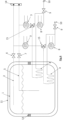
- the lines running outside of the storage tank are designed as vacuum-insulated lines 16 between the components of the respective sampling line.
- cryogenic valves 6 and 7, as well as the heat exchangers 3 and 8, and the shut-off devices 9 can be positioned outside the tank system ( 1 ).
- these components can be stored within the vacuum range ( Fig.2 ) and only place the components outside that are necessary for the barrier.
- the cryogen-carrying lines and components can be connected by means of vacuum-insulated lines 16 (vacuum inuslated lines) to prevent the occurrence of cryogenic to minimize temperatures or other safety-related problems or turn off ( Fig.3 ).
- vacuum-insulated lines are preferably to be used in order to avoid ice formation or air liquefaction.
- the entire extraction flow can be routed through the inner tank heat exchanger 4 (see 1 , 2 and 3 ).
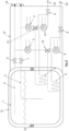
- this can be undesirable in some applications, as a result of which an additional component may be necessary, namely a partial flow control valve 15 (flow control valve).
- a partial flow control valve 15 flow control valve
- This is used, for example, to direct a percentage-controlled mass flow over the inner tank heat exchanger 4, whereby a controlled and thus stabilized working range can be set (see 4 , figure 5 and 6 ).
- a withdrawal line can be provided for the withdrawal of liquid cryogenic medium and designed accordingly.
- the second strand can represent the possibility of extracting from the gaseous medium.
- the storage system despite the new type of piping, can include the option of switching between the type of withdrawal, as may be desirable for better performance of the tank system.
- One method involves installing the components (all components necessary for extraction, following the cryogenic valves) in an extended vacuum area (secondary vacuum) 12, for example at the front or along the tank axis ( Figures 7 - 10 ).
- second vacuum extended vacuum area
- leaks to the outside can be quickly identified and the extraction variant can be changed before the system suffers a failure.
- a separate secondary vacuum region 12 is set up for each of the first and second extraction lines.
- an inert gas atmosphere e.g. helium, nitrogen, argon
- an inert gas atmosphere e.g. helium, nitrogen, argon
- the extraction lines can be monitored using vacuum-insulated pipelines 16 in order to detect any failures and leaks.
- the components for the ancillary system must be designed differently or are installed for a worst-case scenario for both extraction lines. If necessary, this also means that the storage system can have two pressure build-up systems installed, since each extraction line should be able to regulate the pressure of the tank on its own, since this component could also have a fault.
Landscapes
- Engineering & Computer Science (AREA)
- Mechanical Engineering (AREA)
- General Engineering & Computer Science (AREA)
- Physics & Mathematics (AREA)
- Thermal Sciences (AREA)
- Filling Or Discharging Of Gas Storage Vessels (AREA)
Abstract
Description
- Die vorliegende Erfindung betrifft ein Speichersystem zur Speicherung eines kryogenen Mediums, insbesondere zur Speicherung von Wasserstoff. Die Erfindung betrifft auch eine Vorrichtung umfassend ein solches Speichersystem und einen Verbraucher für das im Speicherbehälter des Speichersystems aufgenommene Medium.
- Es ist bekannt, dass kryogene Medien, also tiefkalte und zumindest teilweise flüssige Medien, wie Wasserstoff oder Helium, in einem Speicherbehälter aufbewahrt werden können, um Energie, beispielsweise zum Antrieb eines Fahrzeugs, eines Schiffes, eines Flugzeugs oder einer Rakete zu transportieren. Das Medium liegt dabei üblicherweise teilweise in flüssiger Form im Speicherbehälter vor und teilweise auch in Gasform.
- Bei bekannten kryogenen Speichersystemen sind verschiedenste Leitungen als Verbindung zwischen dem Innentank und der äußeren Umgebung des Speichersystems angeordnet. Diese sind für verschiedene Zwecke erforderlich, wie z.B. zum Leiten von kryogenem flüssigem Medium vom Innentank zum Wärmetauscher oder Verdampfer bis hin zu einem Verbraucher. Manchmal haben solche Speichersysteme auch ein Druckaufbausystem, je nach Type, ein offenes oder geschlossenes System. Ein Druckaufbausystem kann den bei der gasförmigen oder flüssigen Entnahme von beispielsweise Wasserstoff entstehenden Druckabfall ausgleichen. Dies wird in der Regel entweder durch einen Innentankwärmetauscher (geschlossenes Rohrleitungssystem) oder durch direkte Verdampfung (offenes System) gewährleistet.
- Es gibt in bekannten kryogenen Speichersystemen einen Entnahmestrang, welcher eine Verbindung vom Inneren des Tanks bis zu einem Verbraucher darstellt. Bei einem Fehler einer Komponente in diesem Entnahmestrang kommt es üblicherweise zu einem Ausfall (Abschaltung) des Systems, da die Zuführung des Mediums vom Innentank bis zum Verbraucher nicht mehr möglich ist.
- Es ist eine Aufgabe der Erfindung, ein Speichersystem zur Speicherung eines kryogenen Mediums und eine Vorrichtung umfassend ein solches Speichersystem und einen Verbraucher für das im Speicherbehälter des Speichersystems aufgenommene Medium, anzugeben, dass fehlertolerant ist, wobei es insbesondere bei einem Ausfall einer einzelnen Komponente eines Entnahmestrangs zu keinem Totalausfall der Versorgung eines Verbrauchers aus dem Speichersystem kommen soll.
- Die Lösung der Aufgabe erfolgt durch ein Speichersystem zur Speicherung eines kryogenen Mediums, insbesondere zur Speicherung von Wasserstoff, umfassend einen Speicherbehälter zur Aufnahme des Mediums, wobei ein erster Entnahmestrang eine fluidleitende Verbindung vom Innenraum des Speicherbehälters bis zu einem Verbraucheranschluss, zum Anschluss eines Verbrauchers, bildet, wobei in dem ersten Entnahmestrang zumindest ein erstes steuerbares Leitungs-Absperrventil und ein erster Wärmetauscher angeordnet ist, wobei ein vom ersten Entnahmestrang verschiedener zweiter Entnahmestrang eine fluidleitende Verbindung vom Innenraum des Speicherbehälters bis zu einem Verbraucheranschluss, zum Anschluss des selben Verbrauchers, bildet, wobei in dem zweiten Entnahmestrang zumindest ein zweites steuerbares Leitungs-Absperrventil und ein weiterer erster Wärmetauscher angeordnet ist.
- Erfindungsgemäß umfasst der Entnahmestrang eines Speichersystems ein steuerbares Leitungs-Absperrventil um die Entnahme des Mediums aus dem Speicherbehälter in den Entnahmestrang zu steuern und stromabwärts dieses Leitungs-Absperrventils einen ersten Wärmetauscher, der dazu dient das entnommene Medium, insbesondere Wasserstoff, auf die gewünschten Entnahmebedingungen zu temperieren, insbesondere zu erwärmen und eventuell, falls flüssiges Medium entnommen wurde, auch zu verdampfen. Erfindungsgemäß wird ein solcher Entnahmestrang, vom Innenbehälter bis zu einem Verbraucher, redundant zweimal - oder auch öfter- ausgebildet. Daher gibt es erfindungsgemäß einen ersten Entnahmestrang und eine davon verschiedenen zweiten Entnahmestrang, wobei jeder der Entnahmestränge über gleichartige Komponenten verfügt, so dass die Entnahmestränge die selbe Funktion übernehmen können. Insbesondere weist sowohl der erste als auch der zweite Entnahmestrang ein dazugehörendes Leitungs-Absperrventil auf, um den Zufluss in den Entnahmestrang zu steuern, sowie einen zugeordneten Wärmetauscher, um das Medium auf die gewünschten Entnahmebedingungen zu temperieren.
- Bei üblichen kryogenen Speichersystemen ist die Anzahl, sowie die Art der Verrohrung aus thermodynamischen Gründen auf ein Minimum beschränkt. Erfindungsgemäß wird, dem entgegengesetzt, eine höhere Anzahl von Komponenten verwendet.
- Einzelfehler von Komponenten führen daher nicht mehr zu einem Totalausfall (Abschaltung) des Systems, da die Komponenten und die Verbindung zu dem Verbraucher nicht blos einfach mit dem Innentank in Verbindung sind, sondern redundant ausgeführt sind.
- Der erste und zweite Entnahmestrang können beispielsweis beide dazu eingerichtet sein, gasförmiges Medium aus dem Speicherbehälter zu entnehmen oder beide dazu eingerichtet sein, flüssiges Medium aus dem Speicherbehälter zu entnehmen. Es kann auch beispielsweise der erste Entnahmestrang dazu eingerichtet sein, gasförmiges Medium aus dem Speicherbehälter zu entnehmen und der zweite Entnahmestrang dazu eingerichtet sein, flüssiges Medium aus dem Speicherbehälter zu entnehmen.
- Gemäß einer Ausführungsform sind der Verbraucheranschluss des ersten Entnahmestrangs und der Verbraucheranschluss des zweiten Entnahmestrangs zu einem gemeinsamen Anschluss zusammengeführt. In einer alternativen Ausführungsform sind die beiden Verbraucheranschlüsse nicht zu einem gemeinsamen Anschluss zusammengeführt. Die beiden Verbraucheranschlüsse können somit einen gemeinsamen oder zwei separate Anschlüsse am selben Verbraucher bilden.
- Bevorzugt weist der erste Entnahmestrang zusätzlich ein drittes steuerbares Leitungs-Absperrventil unmittelbar vor dem Verbraucheranschluss auf und weist der zweite Entnahmestrang zusätzlich ein weiteres drittes steuerbares Leitungs-Absperrventil unmittelbar vor dem Verbraucheranschluss auf. Das dritte steuerbare Leitungs-Absperrventil kann als Absperreinrichtung vor dem angeschlossenen Verbraucher dienen.
- Vorzugsweise weist der erste Entnahmestrang zusätzlich einen Innentank-Wärmetauscher nach dem ersten Wärmetauscher auf und der zweite Entnahmestrang weist zusätzlich einen weiteren Innentank-Wärmetauscher nach dem weiteren ersten Wärmetauscher auf. Der Innentank-Wärmetauscher in jedem Entnahmestrang dient dazu, den Druck im Inneren des Speicherbehälters mittels des erwärmten entnommenen Mediums zu steuern oder zu regulieren.
- Bevorzugt weist der erste Entnahmestrang zusätzlich einen zweiten Wärmetauscher nach dem Innentank-Wärmetauscher auf und der zweite Entnahmestrang weist zusätzlich einen weiteren zweiten Wärmetauscher nach dem weiteren Innentank-Wärmetauscher auf. Durch die zweiten Wärmetauscher kann auch nach der Wärme-Übertragung durch den Innentank-Wärmetauscher des jeweiligen Entnahmestrangs die Einhaltung der gewünschten Entnahmebedingungen für das Medium sicher gestellt werden.
- Vorzugsweise weist der erste Entnahmestrang zusätzlich ein Teilstromregelventil nach dem ersten steuerbaren Leitungs-Absperrventil und vor dem Innentank-Wärmetauscher auf und weist der zweite Entnahmestrang zusätzlich einen ein weiteres Teilstromregelventil nach dem zweiten steuerbaren Leitungs-Absperrventil und vor dem weiteren Innentank-Wärmetauscher auf. Über die Teilstromregelventile kann wahlweise nur ein Teil des entnommenen und erwärmten Mediums in den Speicherbehälter, zum jeweiligen Innentank-Wärmetauscher zurückgeführt werden.
- Generell können in einem erfindungsgemäßen Speichersystem alle Komponenten des ersten Entnahmestrangs bis zum Verbraucheranschluss, wie Leitungen, Wärmetauscher und Ventile, redundant auch im zweiten Entnahmestrang vorhanden und in der selben Reihenfolge angeordnet sein.
- Bevorzugt ist der Speicherbehälter doppelwandig ausgebildet, mit einem isolierenden Vakuumraum zwischen den beiden Wänden des Speicherbehälters. Gemäß einer Ausführungsform sind das erste und zweite steuerbare Leitungs-Absperrventil und/oder die beiden ersten Wärmetauscher des ersten und zweiten Entnahmestrangs im Vakuumraum angeordnet, besonders bevorzugt auch die zweiten Wärmetauscher des ersten und zweiten Entnahmestrangs.
- Gemäß einer anderen Ausführungsform sind das erste und zweite steuerbare Leitungs-Absperrventil und/oder die ersten Wärmetauscher des ersten und zweiten Entnahmestrangs außerhalb eines Außenbehälters des Speicherbehälters angeordnet, wobei zumindest Teile von Leitungen außerhalb eines Außenbehälters des Speicherbehälters als vakuum-isolierte Leitungen ausgebildet sind.
- Der Speicherbehälter kann auch zumindest einen sekundären Vakuumraum oder Raum mit Inertgasatmosphäre umfassen - insbesondere zusätzlich zu einem Vakuumraum zwischen der Innen- und Außenwand des Behälters -, wobei das erste und zweite steuerbare Leitungs-Absperrventil und/oder die ersten Wärmetauscher des ersten und zweiten Entnahmestrangs - sowie bevorzugt alle Komponenten des ersten und zweiten Entnahmestrangs - im sekundären Vakuumraum oder Raum mit Inertgasatmosphäre angeordnet sind. Besonders bevorzugt sind die Komponenten für den ersten und zweiten Entnahmestrang jeweils in einem separaten sekundären Vakuumbereich oder Raum mit Inertgasatmosphäre, also jeweils zugeordnet zum ersten bzw. zweiten Entnahmestrang, angeordnet, so dass jeder Entnahmestrang seinen eigenen sekundären Vakuumraum oder Raum mit Inertgasatmosphäre besitzt.
- Die Lösung der Aufgabe erfolgt auch durch eine Vorrichtung umfassend ein Speichersystem, wie zuvor beschrieben, und einen Verbraucher für das im Speicherbehälter aufgenommene Medium, wobei der Verbraucheranschluss des ersten Entnahmestrangs und der Verbraucheranschluss des zweiten Entnahmestrangs an den Verbraucher angeschlossen ist. Dabei kann der Verbraucheranschluss des ersten Entnahmestrangs und der Verbraucheranschluss des zweiten Entnahmestrangs zu einem gemeinsamen Anschluss am Verbraucher zusammengeführt sein oder stattdessen nicht zu einem gemeinsamen Anschluss am Verbraucher zusammengeführt sein, also zwei getrennte Anschlüsse am Verbraucher bilden.
- Die Erfindung wird im Folgenden beispielhaft unter Bezugnahme auf die Zeichnungen beschrieben.
- Fig. 1
- ist eine schematische Darstellung eines erfindungsgemäßen Speichersystems.
- Fig. 2
- ist eine schematische Darstellung eines erfindungsgemäßen Speichersystems in einer alternativen Ausführungsform.
- Fig. 3
- ist eine schematische Darstellung eines erfindungsgemäßen Speichersystems in einer alternativen Ausführungsform.
- Fig. 4
- ist eine schematische Darstellung eines erfindungsgemäßen Speichersystems in einer alternativen Ausführungsform.
- Fig. 5
- ist eine schematische Darstellung eines erfindungsgemäßen Speichersystems in einer alternativen Ausführungsform.
- Fig. 6
- ist eine schematische Darstellung eines erfindungsgemäßen Speichersystems in einer alternativen Ausführungsform.
- Fig. 7
- ist eine schematische Darstellung eines erfindungsgemäßen Speichersystems in einer alternativen Ausführungsform.
- Fig. 8
- ist eine schematische Darstellung eines erfindungsgemäßen Speichersystems in einer alternativen Ausführungsform.
- Fig. 9
- ist eine schematische Darstellung eines erfindungsgemäßen Speichersystems in einer alternativen Ausführungsform.
- Fig. 10
- ist eine schematische Darstellung eines erfindungsgemäßen Speichersystems in einer alternativen Ausführungsform.
- In der
Fig.1 ist ein erfindungsgemäßes Speichersystem zur Speicherung eines kryogenen Mediums, insbesondere zur Speicherung von Wasserstoff, dargestellt. - Das Speichersystem umfasst einen Speicherbehälter 1 zur Aufnahme des Mediums. Der Speicherbehälter 1 bildet einen Innenbehälter eines doppelwandigen Behälters, der zusätzlich einen Außenbehälter 11 umfasst. Zwischen Außenbehälter 11 und Innenbehälter, also Speicherbehälter 1, ist ein Vakuum gebildet. Zwischen Außenbehälter 11 und Innenbehälter sind zudem abschnittsweise Aufhängungen 13 angeordnet, um die beiden Schalen des doppelwandigen Behälters zueinander zu positionieren.
- Das kryogene Medium, insbesondere Wasserstoff, befindet sich im unteren Bereich des Speicherbehälters 1, nämlich unterhalb der in den Fig. als Wellenlinie dargestellten Flüssigkeitsoberfläche als Flüssigkeit im Behälter, oberhalb der wellenförmigen Flüssigkeitsoberfläche in gasförmigem Zustand.
- Eine Gasentnahmeleitung 2 ist zur Entnahme des gasförmigen Mediums aus dem Speicherbehälter 1 eingerichtet, so dass das freie Ende der Gasentnahmeleitung 2 oberhalb der Flüssigkeitsoberfläche, in der Nähe der Decke des Speicherbehälters 1, im Speicherbehälter 1 endet. Mit der Gasentnahmeleitung 2 beginnt der erste Entnahmestrang.
- Eine Flüssigentnahmeleitung 5 ist zur Entnahme des flüssigen Mediums aus dem Speicherbehälter 1 eingerichtet, so dass das freie Ende der Flüssigentnahmeleitung 5 unterhalb der Flüssigkeitsoberfläche, in der Nähe des Bodens des Speicherbehälters 1, im Speicherbehälter 1 endet. Mit der Flüssigentnahmeleitung 5 beginnt der zweite Entnahmestrang.
- Die Begriffe "Decken" und "Boden" beziehen sich dabei auf die übliche Einbaulage des Speicherbehälters, beispielsweise in einer fahrenden, schwimmenden oder fliegenden Transportvorrichtung, wobei die Gravitation in einem Normalbetrieb der Transportvorrichtung in Richtung zum Boden des Speicherbehälters wirkt.
- In der Gasentnahmeleitung 2 ist ein erstes steuerbares Leitungs-Absperrventil 6 angeordnet und in der Flüssigentnahmeleitung 5 ist ein zweites steuerbares Leitungs-Absperrventil 7 angeordnet. Beide Leitungs-Absperrventile befinden sich außerhalb des Speicherbehälters 1. In der
Fig. 1 befinden sich die Leitungs-Absperrventile auch außerhalb des Außenbehälters 11. - In der alternativen Ausführung des Speichersystems die in
Fig. 2 dargestellt ist, sind die beiden Leitungs-Absperrventile 6, 7 innerhalb des Außenbehälters 11 angeordnet, also zwischen dem Innenbehälter, Speicherbehälter 1, und dem Außenbehälter 11 des doppelwandigen Speicherbehälters, nämlich im Vakuumraum. - Die Leitungs-Absperrventile sind durch eine Steuervorrichtung, die ebenfalls im Vakuumraum (
Fig.2 ) oder außerhalb des gesamten Behälters (Fig. 1 ) angeordnet sein kann, steuerbar. Dabei kann die Strömung durch die Leitungs-Absperrventile bevorzugt nicht nur unterbrochen werden oder freigegeben werden, sondern auch reduziert werden. - Über die Gasentnahmeleitung 2 und/oder die Flüssigentnahmeleitung 5, bevorzugt auch über das erste Leitungs-Absperrventil 6 und/oder das zweite Leitungs-Absperrventil 7, kann auch eine Betankung des Speicherbehälters 1 aus einer Betankungsvorrichtung 14 erfolgen.
- Die Gasentnahmeleitung 2 und die Flüssigentnahmeleitung 5 verlaufen auch nach den beiden Leitungs-Absperrventilen 6, 7 als zwei getrennte Leitungen, mit ihren jeweils eigenen, zugeordneten Komponenten, und bilden daher zwei getrennte Entnahmestränge.
- Die Gasentnahmeleitung 2 und die Flüssigentnahmeleitung 5 sind als getrennte Entnahmestränge mit dem jeweils zugeordneten, außerhalb des Speicherbehälters 1, beispielsweise zwischen Speicherbehälter 1 und Außenbehälter 11 des doppelwandigen Speicherbehälters (
Fig. 2 ), angeordneten, ersten Wärmetauscher 3 zur Erwärmung des entnommenen Mediums strömungsverbundenen. - Stromabwärts des ersten Wärmetauschers 3 ist innerhalb des Speicherbehälters 1 jeweils ein Innentank-Wärmetauscher 4 zur Erwärmung des flüssigen Mediums im Speicherbehälter 1 angeordnet, der vom erwärmten, aus dem Speicherbehälter 1 entnommenen Medium durchflossen wird. Durch die Erwärmung am Innentank-Wärmetauscher 4 wird das flüssige Medium im Speicherbehälter 1 teilweise erwärmt und verdampft.
- In der Gasentnahmeleitung 2 und in der Flüssigentnahmeleitung 5 der Ausführung gemäß
Fig. 1 bis Fig. 3 ist kein steuerbares Dreiwegeventil, also kein Teilstromventil 15 angeordnet, so dass das gesamte durch die Gasentnahmeleitung 2 und/oder durch die Flüssigentnahmeleitung 5 entnommene und vom ersten Wärmetauscher 3 erwärmte Medium zum Innentank-Wärmetauscher 4 gelangt. In den Ausführungen gemäßFig. 4 bis Fig. 4 ist in jedem Entnahmestrang ein Teilstromventil 15 angeordnet, so dass wahlweise lediglich ein Teil des durch die Gasentnahmeleitung 2 und/oder durch die Flüssigentnahmeleitung 5 entnommenen und vom ersten Wärmetauscher 3 erwärmten Mediums zum jeweiligen Innentank-Wärmetauscher 4 gelangt. - Stromabwärts des jeweiligen Innentank-Wärmetauschers 4 und außerhalb des Speicherbehälters 1, außerhalb (
Fig. 1 ) oder innerhalb (Fig. 2 ) des Außenbehälters 11 des doppelwandigen Behälters, ist jeweils ein zweiter Wärmetauscher 8 zur Erwärmung des Mediums im ersten Entnahmestrang und im zweiten Entnahmestrang angeordnet. - Das über den ersten und/oder zweiten Entnahmestrang strömende Medium wird stromabwärts des jeweiligen Innentank-Wärmetauschers 4 einem selben Verbraucher über einen jeweiligen Verbraucheranschluss 10 zugeführt, insbesondere einer Brennstoffzelle als Verbraucher. Zwischen dem zweiten Wärmetauscher 8 und dem Verbraucher 10 ist in jedem Entnahmestrang ein drittes Leitungs-Absperrventil 9 angeordnet.
- Die Ausführungsform der
Fig. 2 unterscheidet sich dadurch von derFig. 1 , dass steuerungsrelevante Komponenten beider Entnahmestränge des Speichersystems, wie die ersten Wärmetauscher 3, die zweiten Wärmetauscher 8, das erste Leitungs-Absperrventil 6 und das zweite Leitungs-Absperrventil 8, innerhalb des Außenbehälters 11 angeordnet sind, nicht außerhalb des Außenbehälters 11 wie inFig. 1 , und somit im Zwischenraum des doppelwandigen Behälters angeordnet sind, der einen Vakuumraum bildet. - Dabei können zwei getrennte Bereiche des Vakuumraumes ausschließlich für die Wärmetauscher 3, 8 des ersten Entnahmestrangs und für die Wärmetauscher 3, 8 des zweiten Entnahmestrangs verwendet werden. Hierdurch können Fehler in einem Entnahmestrang auf einfachere Weise entdeckt und dem betreffenden Entnahmestrang zugewiesen werden. Die Trennung der beiden Bereiche des Vakuumraumes kann durch die Aufhängungen 13 erfolgen. Die Trennung kann aber auch durch mindestens einen zusätzlichen sekundären Vakuumraum 12 erfolgen. Auch können alle Komponenten beider Entnahmestränge in einem zusätzlichen sekundären Vakuumraum 12 verbaut sein, um im Falle eines Fehlers das zwischen Speicherbehälter 1 und Außenbehälter 11 befindliche primäre Vakuum nicht zu zerstören und damit den gesamten Inhalt des Speicherbehälters 1 über die Sicherheitseinrichtung zu entleeren (
Fig. 7 - 10 ). Anstelle des sekundären Vakuums 12 kann auch eine Inertgasatmosphäre (z.B. Helium, Stickstoff, Argon) im Raum 12 hergestellt werden. - In der Ausführung der
Fig. 3 sind die außerhalb des Speicherbehälters verlaufenden Leitungen zwischen den Komponenten des jeweiligen Entnahmestrangs als vakuum-isolierte Leitungen 16 ausgebildet. - Somit können insgesamt die kryogenen Ventile 6 und 7, sowie die Wärmetauscher 3 und 8, als auch die Absperreinrichtungen 9 außerhalb des Tanksystems positioniert werden (
Fig. 1 ). Beispielsweise bei kryogenen Speichersystemen, wo dies nicht einfach technisch realisiert werden kann aufgrund der sehr tiefen Temperaturen und damit verbundenen Eisbildungen oder anderen sicherheitsrelevanten Gegebenheiten, kann man diese Komponenten innerhalb des Vakuumbereichs (Fig.2 ) platzieren und nur die Komponenten außerhalb platzieren, die für die Absperrung notwendig sind. Als alternative, um beispielsweise den Bauraum besser nutzen zu können, weil keine Komponenten zwischen Innentank 1 und Außentank 11 platziert werden müssen, können die kryogenführenden Leitungen und Bauteile mittels vakuum-isolierten Leitungen 16 (Vacuum inuslated Lines) verbunden werden, um ein Auftreten von kryogenen Temperaturen oder anderen sicherheitsrelevanten Problemen zu minimieren oder abzustellen (Fig.3 ). Zumindest sind vorzugsweise bis zu den ersten Wärmetauschern 3 vakuumisolierte Leitungen zu verwenden, um Eisbildung oder Luftverflüssigung zu vermeiden. - Wie bereits erwähnt, kann man den gesamten Entnahmestrom durch den Innentank-Wärmeübertrager 4 leiten (siehe
Fig. 1 ,Fig. 2 undFig. 3 ). Dies kann aber in manchen Anwendungsfällen unerwünscht sein, wodurch ein weiteres Bauteil notwendig sein kann, nämlich ein Teilstromregelventil 15 (Flow Control Valve). Dies dient beispielsweise dazu, einen prozentuell geregelten Massenstrom über den Innentankwärmeübertrager 4 zu leiten, wodurch ein kontrollierter und damit stabilisierter Arbeitsbereich eingestellt werden kann (sieheFig. 4 ,Fig. 5 undFig. 6 ). - Um für mobile Anwendungen eine Entnahme des Mediums auch bei Einzelfehlern sicherstellen zu können, wird erfindungsgemäß eine Redundanz in das Speichersystem eingebracht. Eine Verdoppelung der kryogenen Ventile, also des ersten und zweiten steuerbaren Leitungs-Absperrventils 6 und 7 ist dabei jedoch nicht notwendig. Durch diese Maßnahme kann ein System realisiert werden welches Ausfälle von einzelnen Komponenten kompensieren kann und daher auch den Verlust der Funktionalität des Speichersystems verhindern kann. Dabei gibt es zwei Entnahmestränge, die sich in der Art der Entnahme (Gas, Flüssig) unterscheiden können. Durch die redundante Ausführung mit zwei nicht miteinander verbundenen Entnahmesträngen kann bei Ausfall oder Undichtheit einer Komponente in einem Entnahmestrang, der jeweils andere die volle Funktionsfähigkeit des anderen übernehmen. Insbesondere in der Luftfahrt, Schifffahrt und im Automotiven Sektor ist ein solches Szenario, bei dem ein einzelner Ausfall oder ein einziger Fehler zur Abschaltung des gesamten Tanksystems führt, nicht wünschenswert. Ein weiterer Vorteil ist, dass trotz redundanter Ausführung nicht wesentlich mehr Komponenten benötigt werden.
- Ein Entnahmestrang kann für die Entnahme von flüssigem kryogenem Medium vorgesehen und dementsprechend ausgelegt sein. Der zweite Strang kann die Möglichkeit der Entnahme vom gasförmigen Medium darstellen. Dadurch kann das Speichersystem, trotz neuer Art der Verrohrung, die Möglichkeit umfassen zwischen der Art der Entnahme zu wechseln, wie es für eine bessere Performance des Tanksystems wünschenswert sein kann.
- Um im Fall eines einzelnen Fehlers den Fehler zu erkennen und den Wechsel der Entnahmeart zu ermöglichen, können verschiedene Methoden zur Überwachung des Systems realisiert werden:
Eine Methode beinhaltet das Verbauen der Komponenten (alle Komponente die für die Entnahme notwendig sind, im Anschluss an die kryogenen Ventile) in einen erweiterten Vakuumbereich (Sekundärvakuum) 12, beispielsweise stirnseitig oder entlang der Tankachse (Fig. 7 - 10 ). Dadurch sind Leckagen nach außen schnell erkennbar und ein Wechsel der Entnahmevariante kann realisiert werden, ehe das System einen Ausfall erleidet. Hierbei ist als weitere Variante von Vorteil, wenn für den ersten und zweiten Entnahmestrang jeweils ein separater sekundärer Vakuumbereich 12 eingerichtet ist. Es sei auch hier angemerkt, dass anstelle des sekundären Vakuums auch eine Inertgasatmosphäre (zB. Helium, Stickstoff, Argon) im Raum 12 hergestellt werden kann. - Beispielsweise wenn man diesen Bauraum nicht nutzen kann, können, in einer zweiten Methode, die Entnahmeleitungen mittels vakuum-isolierten Rohrleitungen 16 überwacht werden, um gegebenenfalls Ausfälle und Leckagen zu erkennen.
- Die Komponenten für das Nebensystem müssen dementsprechend unterschiedlich ausgelegt werden bzw. werden jeweils für ein Worst-Case Szenario eingebaut für beide Entnahmestränge. Wenn notwendig, bedeutet dies ebenso, dass das Speichersystem zwei Druckaufbausysteme verbaut haben kann, da jeder Entnahmestrang für sich die Möglichkeit haben sollte, den Druck des Tanks zu regulieren, da auch diese Komponente einen Fehler aufweisen könnte.
-
- 1
- Speicherbehälter
- 2
- Gasentnahmeleitung
- 3
- erster Wärmetauscher
- 4
- erster Innentank-Wärmetauscher
- 5
- Flüssigentnahmeleitung
- 6
- erstes steuerbares Leitungs-Absperrventil
- 7
- zweites steuerbares Leitungs-Absperrventil
- 8
- zweiter Wärmetauscher
- 9
- drittes steuerbares Leitungs-Absperrventil
- 10
- Verbraucheranschluss
- 11
- Außenbehälter
- 12
- sekundärer Vakuumraum/Raum für Inertgasatmosphäre
- 13
- Aufhängung
- 14
- Betankungsvorrichtung
- 15
- Teilstromregelventil
- 16
- Vakuum-isolierte Leitung
Claims (11)
- Speichersystem zur Speicherung eines kryogenen Mediums, insbesondere zur Speicherung von Wasserstoff, umfassend einen Speicherbehälter (1) zur Aufnahme des Mediums, wobei ein erster Entnahmestrang eine fluidleitende Verbindung vom Innenraum des Speicherbehälters (1) bis zu einem Verbraucheranschluss (10), zum Anschluss eines Verbrauchers, bildet, wobei in dem ersten Entnahmestrang zumindest ein erstes steuerbares Leitungs-Absperrventil (6) und ein erster Wärmetauscher (3) angeordnet ist,
dadurch gekennzeichnet, dass ein vom ersten Entnahmestrang verschiedener zweiter Entnahmestrang eine fluidleitende Verbindung vom Innenraum des Speicherbehälters (1) bis zu einem Verbraucheranschluss (10), zum Anschluss des selben Verbrauchers, bildet, wobei in dem zweiten Entnahmestrang zumindest ein zweites steuerbares Leitungs-Absperrventil (7) und ein weiterer erster Wärmetauscher (3) angeordnet ist. - Speichersystem nach Anspruch 1,
dadurch gekennzeichnet, dass der Verbraucheranschluss (10) des ersten Entnahmestrangs und der Verbraucheranschluss (10) des zweiten Entnahmestrangs zu einem gemeinsamen Anschluss zusammengeführt sind oder nicht zu einem gemeinsamen Anschluss zusammengeführt sind. - Speichersystem nach einem der zuvor genannten Ansprüche,
dadurch gekennzeichnet, dass der erste Entnahmestrang zusätzlich ein drittes steuerbares Leitungs-Absperrventil (9) unmittelbar vor dem Verbraucheranschluss (10) aufweist und der zweite Entnahmestrang zusätzlich ein weiteres drittes steuerbares Leitungs-Absperrventil (9) unmittelbar vor dem Verbraucheranschluss (10) aufweist. - Speichersystem nach einem der zuvor genannten Ansprüche,
dadurch gekennzeichnet, dass der erste Entnahmestrang zusätzlich einen Innentank-Wärmetauscher (4) nach dem erster Wärmetauscher (3) aufweist und der zweite Entnahmestrang zusätzlich einen weiteren Innentank-Wärmetauscher (4) nach dem weiteren ersten Wärmetauscher (3) aufweist - Speichersystem nach Anspruch 4,
dadurch gekennzeichnet, dass der erste Entnahmestrang zusätzlich einen zweiten Wärmetauscher (8) nach dem Innentank-Wärmetauscher (4) aufweist und der zweite Entnahmestrang zusätzlich einen weiteren zweiten Wärmetauscher (8) nach dem weiteren Innentank-Wärmetauscher (4) aufweist. - Speichersystem nach Anspruch 4 oder 5,
dadurch gekennzeichnet, dass der erste Entnahmestrang zusätzlich ein Teilstromregelventil (15) nach dem ersten steuerbaren Leitungs-Absperrventil (6) und vor dem Innentank-Wärmetauscher (4) aufweist und der zweite Entnahmestrang zusätzlich einen ein weiteres Teilstromregelventil (15) nach dem zweiten steuerbaren Leitungs-Absperrventil (7) und vor dem weiteren Innentank-Wärmetauscher (4) aufweist. - Speichersystem nach einem der zuvor genannten Ansprüche,
dadurch gekennzeichnet, dass alle Komponenten des ersten Entnahmestrangs bis zum Verbraucheranschluss (10), wie Leitungen, Wärmetauscher und Ventile, redundant auch im zweiten Entnahmestrang vorhanden und in der selben Reihenfolge angeordnet sind. - Speichersystem nach einem der zuvor genannten Ansprüche,
dadurch gekennzeichnet, dass der Speicherbehälter (1) doppelwandig ausgebildet ist, mit einem isolierenden Vakuumraum zwischen den beiden Wänden des Speicherbehälters (1), wobei das erste und zweite steuerbare Leitungs-Absperrventil (6, 7) und/oder die ersten Wärmetauscher (3) des ersten und zweiten Entnahmestrangs im Vakuumraum angeordnet sind, bevorzugt auch die zweiten Wärmetauscher (8) des ersten und zweiten Entnahmestrangs. - Speichersystem nach einem der zuvor genannten Ansprüche,
dadurch gekennzeichnet, dass der Speicherbehälter (1) doppelwandig ausgebildet ist, mit einem isolierenden Vakuumraum zwischen den beiden Wänden des Speicherbehälters (1), wobei das erste und zweite steuerbare Leitungs-Absperrventil (6, 7) und/oder die ersten Wärmetauscher (3) des ersten und zweiten Entnahmestrangs außerhalb eines Außenbehälters (11) des Speicherbehälters (1) angeordnet sind, wobei zumindest Teile von Leitungen außerhalb des Außenbehälters (11) des Speicherbehälters (1) als vakuum-isolierte Leitungen (16) ausgebildet sind. - Speichersystem nach einem der zuvor genannten Ansprüche,
dadurch gekennzeichnet, dass der Speicherbehälter (1) zumindest einen sekundären Vakuumraum oder Raum mit Inertgasatmosphäre (12) umfasst, wobei das erste und zweite steuerbare Leitungs-Absperrventil (6, 7) und/oder die ersten Wärmetauscher (3) des ersten und zweiten Entnahmestrangs im sekundären Vakuumraum oder Raum mit Inertgasatmosphäre (12) angeordnet sind, wobei bevorzugt die Komponenten für den ersten und zweiten Entnahmestrang jeweils in einem separaten sekundären Vakuumbereich oder Raum mit Inertgasatmosphäre (12) des ersten bzw. zweiten Entnahmestrangs angeordnet sind. - Vorrichtung umfassend ein Speichersystem nach einem der zuvor genannten Ansprüche und einen Verbraucher für das im Speicherbehälter aufgenommene Medium,
dadurch gekennzeichnet, dass der Verbraucheranschluss (10) des ersten Entnahmestrangs und der Verbraucheranschluss (10) des zweiten Entnahmestrangs an den Verbraucher angeschlossen ist, wobei der Verbraucheranschluss (10) des ersten Entnahmestrangs und der Verbraucheranschluss (10) des zweiten Entnahmestrangs zu einem gemeinsamen Anschluss am Verbraucher zusammengeführt sind oder nicht zu einem gemeinsamen Anschluss am Verbraucher zusammengeführt sind.
Applications Claiming Priority (1)
| Application Number | Priority Date | Filing Date | Title |
|---|---|---|---|
| DE102021213644.3A DE102021213644B4 (de) | 2021-12-01 | 2021-12-01 | Kryogen-Speichersystem |
Publications (2)
| Publication Number | Publication Date |
|---|---|
| EP4191120A1 true EP4191120A1 (de) | 2023-06-07 |
| EP4191120B1 EP4191120B1 (de) | 2025-06-04 |
Family
ID=84370701
Family Applications (1)
| Application Number | Title | Priority Date | Filing Date |
|---|---|---|---|
| EP22210785.6A Active EP4191120B1 (de) | 2021-12-01 | 2022-12-01 | Kryogen-speichersystem |
Country Status (4)
| Country | Link |
|---|---|
| US (1) | US20230167947A1 (de) |
| EP (1) | EP4191120B1 (de) |
| CN (1) | CN116202019A (de) |
| DE (1) | DE102021213644B4 (de) |
Citations (3)
| Publication number | Priority date | Publication date | Assignee | Title |
|---|---|---|---|---|
| US20070193275A1 (en) * | 2003-06-16 | 2007-08-23 | Vitaliano Russo | Method And Apparatus For Generating Compressed Air From Liquefied Air, For Supplying Compressed Air To An Engine |
| DE102020206689B3 (de) * | 2020-05-28 | 2021-08-19 | Magna Steyr Fahrzeugtechnik Ag & Co Kg | Kryogen-Speichersystem |
| WO2022106053A1 (de) * | 2020-11-19 | 2022-05-27 | Linde Gmbh | Verfahren und fördervorrichtung |
Family Cites Families (5)
| Publication number | Priority date | Publication date | Assignee | Title |
|---|---|---|---|---|
| DE4320556A1 (de) * | 1993-06-21 | 1994-12-22 | Linde Ag | Speicherbehälter für kryogene Medien |
| DE102006025656B4 (de) | 2006-06-01 | 2017-09-21 | Bayerische Motoren Werke Aktiengesellschaft | Vorrichtung zur Kraftstoffspeicherung und -förderung von kryogenem Kraftstoff |
| DE102006025657B4 (de) * | 2006-06-01 | 2016-11-03 | Bayerische Motoren Werke Aktiengesellschaft | Vorrichtung zur Förderung von kryogen gespeichertem Kraftstoff |
| DE102012204818A1 (de) * | 2012-03-26 | 2013-09-26 | Bayerische Motoren Werke Aktiengesellschaft | Betriebsverfahren für einen Kryo-Drucktank |
| US9347615B2 (en) * | 2013-09-13 | 2016-05-24 | Air Products And Chemicals, Inc. | Low-loss cryogenic fluid supply system and method |
-
2021
- 2021-12-01 DE DE102021213644.3A patent/DE102021213644B4/de active Active
-
2022
- 2022-11-25 US US18/058,787 patent/US20230167947A1/en active Pending
- 2022-11-30 CN CN202211522380.6A patent/CN116202019A/zh active Pending
- 2022-12-01 EP EP22210785.6A patent/EP4191120B1/de active Active
Patent Citations (3)
| Publication number | Priority date | Publication date | Assignee | Title |
|---|---|---|---|---|
| US20070193275A1 (en) * | 2003-06-16 | 2007-08-23 | Vitaliano Russo | Method And Apparatus For Generating Compressed Air From Liquefied Air, For Supplying Compressed Air To An Engine |
| DE102020206689B3 (de) * | 2020-05-28 | 2021-08-19 | Magna Steyr Fahrzeugtechnik Ag & Co Kg | Kryogen-Speichersystem |
| WO2022106053A1 (de) * | 2020-11-19 | 2022-05-27 | Linde Gmbh | Verfahren und fördervorrichtung |
Also Published As
| Publication number | Publication date |
|---|---|
| US20230167947A1 (en) | 2023-06-01 |
| DE102021213644B4 (de) | 2026-03-26 |
| CN116202019A (zh) | 2023-06-02 |
| EP4191120B1 (de) | 2025-06-04 |
| DE102021213644A1 (de) | 2023-06-01 |
Similar Documents
| Publication | Publication Date | Title |
|---|---|---|
| DE102020206689B3 (de) | Kryogen-Speichersystem | |
| EP3722652B1 (de) | Speicherbehälter für tiefkaltes flüssiggas | |
| DE102018207494A1 (de) | Druckentlastungssystem zur Druckentlastung von mindestens einem Druckbehälter sowie Druckbehältersystem und Kraftfahrzeug | |
| EP3444520A1 (de) | Kühlung einer abdampfung von flüssiggas zum antrieb von maschinen, anlagen oder fahrzeugen | |
| DE102008063563A1 (de) | Kraftstoffversorgungssystem mit einem Tieftemperaturtank | |
| DE102018005807A1 (de) | Verflüssigung eines gasförmigen Mediums | |
| DE19945462A1 (de) | Verfahren zum Entnehmen eines gasförmigen und flüssigen kryogenen Mediums aus einem Speicherbehälter und Speicherbehälter | |
| DE102017201045A1 (de) | Druckbehältersystem für ein Kraftfahrzeug | |
| EP4191120B1 (de) | Kryogen-speichersystem | |
| EP4155601A1 (de) | Kryogen-speichersystem | |
| EP4013990B1 (de) | Kryobehälter mit rohrdurchführungsmodul | |
| DE102021104334A1 (de) | Anschlusselement, Druckbehälterbaugruppe und Kraftfahrzeug | |
| WO2022067362A1 (de) | Sicherheitsentnahmesystem für einen kryobehälter | |
| AT526730B1 (de) | Kryotank | |
| WO2021026582A1 (de) | Kryobehälter und nebensystem zum befüllen und entlüften des kryobehälters | |
| EP4314631A1 (de) | System zur überprüfung der funktionstüchtigkeit eines überdruckventils | |
| WO2024217952A1 (de) | Kraftstoffsystem zur versorgung eines luftfahrzeuges mit wasserstoff, sowie verfahren und luftfahrzeug | |
| DE19850911C2 (de) | Flüssiggas-Kühlungssystem zur Kühlung eines Verbrauchers auf Tieftemperatur | |
| DE19704361C1 (de) | Betankungseinrichtung für kryogene Kraftstoffe und Verfahren zum abgasfreien Betanken von Fahrzeugen jeder Art mit unterkühlter Flüssigkeit aus einer derartigen Betankungseinrichtung | |
| DE102019134166A1 (de) | Brennstoffversorgungssystem und Kraftfahrzeug | |
| DE102017217348A1 (de) | Druckbehältersystem und Verfahren zum Zuführen von Brennstoff aus einem Druckbehältersystem | |
| DE102020120493A1 (de) | Druckbehälteranordnung, Brennstoffversorgungseinrichtung und Kraftfahrzeug | |
| EP4290119A1 (de) | Kryogen speichersystem | |
| DE102022207627B4 (de) | Kryotankvorrichtung | |
| DE202013010271U1 (de) | Seeschiff mit Flüssiggastank |
Legal Events
| Date | Code | Title | Description |
|---|---|---|---|
| PUAI | Public reference made under article 153(3) epc to a published international application that has entered the european phase |
Free format text: ORIGINAL CODE: 0009012 |
|
| STAA | Information on the status of an ep patent application or granted ep patent |
Free format text: STATUS: THE APPLICATION HAS BEEN PUBLISHED |
|
| AK | Designated contracting states |
Kind code of ref document: A1 Designated state(s): AL AT BE BG CH CY CZ DE DK EE ES FI FR GB GR HR HU IE IS IT LI LT LU LV MC ME MK MT NL NO PL PT RO RS SE SI SK SM TR |
|
| STAA | Information on the status of an ep patent application or granted ep patent |
Free format text: STATUS: REQUEST FOR EXAMINATION WAS MADE |
|
| 17P | Request for examination filed |
Effective date: 20231114 |
|
| RBV | Designated contracting states (corrected) |
Designated state(s): AL AT BE BG CH CY CZ DE DK EE ES FI FR GB GR HR HU IE IS IT LI LT LU LV MC ME MK MT NL NO PL PT RO RS SE SI SK SM TR |
|
| GRAP | Despatch of communication of intention to grant a patent |
Free format text: ORIGINAL CODE: EPIDOSNIGR1 |
|
| STAA | Information on the status of an ep patent application or granted ep patent |
Free format text: STATUS: GRANT OF PATENT IS INTENDED |
|
| RIC1 | Information provided on ipc code assigned before grant |
Ipc: F17C 3/08 20060101AFI20250311BHEP |
|
| INTG | Intention to grant announced |
Effective date: 20250320 |
|
| GRAS | Grant fee paid |
Free format text: ORIGINAL CODE: EPIDOSNIGR3 |
|
| GRAA | (expected) grant |
Free format text: ORIGINAL CODE: 0009210 |
|
| STAA | Information on the status of an ep patent application or granted ep patent |
Free format text: STATUS: THE PATENT HAS BEEN GRANTED |
|
| AK | Designated contracting states |
Kind code of ref document: B1 Designated state(s): AL AT BE BG CH CY CZ DE DK EE ES FI FR GB GR HR HU IE IS IT LI LT LU LV MC ME MK MT NL NO PL PT RO RS SE SI SK SM TR |
|
| REG | Reference to a national code |
Ref country code: GB Ref legal event code: FG4D Free format text: NOT ENGLISH |
|
| REG | Reference to a national code |
Ref country code: CH Ref legal event code: EP |
|
| REG | Reference to a national code |
Ref country code: DE Ref legal event code: R096 Ref document number: 502022004149 Country of ref document: DE |
|
| REG | Reference to a national code |
Ref country code: IE Ref legal event code: FG4D Free format text: LANGUAGE OF EP DOCUMENT: GERMAN |
|
| REG | Reference to a national code |
Ref country code: NL Ref legal event code: MP Effective date: 20250604 |
|
| PG25 | Lapsed in a contracting state [announced via postgrant information from national office to epo] |
Ref country code: FI Free format text: LAPSE BECAUSE OF FAILURE TO SUBMIT A TRANSLATION OF THE DESCRIPTION OR TO PAY THE FEE WITHIN THE PRESCRIBED TIME-LIMIT Effective date: 20250604 Ref country code: ES Free format text: LAPSE BECAUSE OF FAILURE TO SUBMIT A TRANSLATION OF THE DESCRIPTION OR TO PAY THE FEE WITHIN THE PRESCRIBED TIME-LIMIT Effective date: 20250604 |
|
| REG | Reference to a national code |
Ref country code: LT Ref legal event code: MG9D |
|
| PG25 | Lapsed in a contracting state [announced via postgrant information from national office to epo] |
Ref country code: GR Free format text: LAPSE BECAUSE OF FAILURE TO SUBMIT A TRANSLATION OF THE DESCRIPTION OR TO PAY THE FEE WITHIN THE PRESCRIBED TIME-LIMIT Effective date: 20250905 Ref country code: NO Free format text: LAPSE BECAUSE OF FAILURE TO SUBMIT A TRANSLATION OF THE DESCRIPTION OR TO PAY THE FEE WITHIN THE PRESCRIBED TIME-LIMIT Effective date: 20250904 |
|
| PG25 | Lapsed in a contracting state [announced via postgrant information from national office to epo] |
Ref country code: PL Free format text: LAPSE BECAUSE OF FAILURE TO SUBMIT A TRANSLATION OF THE DESCRIPTION OR TO PAY THE FEE WITHIN THE PRESCRIBED TIME-LIMIT Effective date: 20250604 |
|
| PG25 | Lapsed in a contracting state [announced via postgrant information from national office to epo] |
Ref country code: BG Free format text: LAPSE BECAUSE OF FAILURE TO SUBMIT A TRANSLATION OF THE DESCRIPTION OR TO PAY THE FEE WITHIN THE PRESCRIBED TIME-LIMIT Effective date: 20250604 |
|
| PG25 | Lapsed in a contracting state [announced via postgrant information from national office to epo] |
Ref country code: HR Free format text: LAPSE BECAUSE OF FAILURE TO SUBMIT A TRANSLATION OF THE DESCRIPTION OR TO PAY THE FEE WITHIN THE PRESCRIBED TIME-LIMIT Effective date: 20250604 |
|
| PG25 | Lapsed in a contracting state [announced via postgrant information from national office to epo] |
Ref country code: RS Free format text: LAPSE BECAUSE OF FAILURE TO SUBMIT A TRANSLATION OF THE DESCRIPTION OR TO PAY THE FEE WITHIN THE PRESCRIBED TIME-LIMIT Effective date: 20250904 |
|
| PG25 | Lapsed in a contracting state [announced via postgrant information from national office to epo] |
Ref country code: LV Free format text: LAPSE BECAUSE OF FAILURE TO SUBMIT A TRANSLATION OF THE DESCRIPTION OR TO PAY THE FEE WITHIN THE PRESCRIBED TIME-LIMIT Effective date: 20250604 |
|
| PG25 | Lapsed in a contracting state [announced via postgrant information from national office to epo] |
Ref country code: NL Free format text: LAPSE BECAUSE OF FAILURE TO SUBMIT A TRANSLATION OF THE DESCRIPTION OR TO PAY THE FEE WITHIN THE PRESCRIBED TIME-LIMIT Effective date: 20250604 |
|
| PG25 | Lapsed in a contracting state [announced via postgrant information from national office to epo] |
Ref country code: PT Free format text: LAPSE BECAUSE OF FAILURE TO SUBMIT A TRANSLATION OF THE DESCRIPTION OR TO PAY THE FEE WITHIN THE PRESCRIBED TIME-LIMIT Effective date: 20251006 |
|
| PG25 | Lapsed in a contracting state [announced via postgrant information from national office to epo] |
Ref country code: IS Free format text: LAPSE BECAUSE OF FAILURE TO SUBMIT A TRANSLATION OF THE DESCRIPTION OR TO PAY THE FEE WITHIN THE PRESCRIBED TIME-LIMIT Effective date: 20251004 |
|
| PGFP | Annual fee paid to national office [announced via postgrant information from national office to epo] |
Ref country code: DE Payment date: 20251211 Year of fee payment: 4 |
|
| PG25 | Lapsed in a contracting state [announced via postgrant information from national office to epo] |
Ref country code: SM Free format text: LAPSE BECAUSE OF FAILURE TO SUBMIT A TRANSLATION OF THE DESCRIPTION OR TO PAY THE FEE WITHIN THE PRESCRIBED TIME-LIMIT Effective date: 20250604 |
|
| PGFP | Annual fee paid to national office [announced via postgrant information from national office to epo] |
Ref country code: AT Payment date: 20260113 Year of fee payment: 4 |
|
| PGFP | Annual fee paid to national office [announced via postgrant information from national office to epo] |
Ref country code: FR Payment date: 20251229 Year of fee payment: 4 |
|
| PG25 | Lapsed in a contracting state [announced via postgrant information from national office to epo] |
Ref country code: CZ Free format text: LAPSE BECAUSE OF FAILURE TO SUBMIT A TRANSLATION OF THE DESCRIPTION OR TO PAY THE FEE WITHIN THE PRESCRIBED TIME-LIMIT Effective date: 20250604 |
|
| PG25 | Lapsed in a contracting state [announced via postgrant information from national office to epo] |
Ref country code: EE Free format text: LAPSE BECAUSE OF FAILURE TO SUBMIT A TRANSLATION OF THE DESCRIPTION OR TO PAY THE FEE WITHIN THE PRESCRIBED TIME-LIMIT Effective date: 20250604 |
|
| PG25 | Lapsed in a contracting state [announced via postgrant information from national office to epo] |
Ref country code: SK Free format text: LAPSE BECAUSE OF FAILURE TO SUBMIT A TRANSLATION OF THE DESCRIPTION OR TO PAY THE FEE WITHIN THE PRESCRIBED TIME-LIMIT Effective date: 20250604 |
|
| PG25 | Lapsed in a contracting state [announced via postgrant information from national office to epo] |
Ref country code: IT Free format text: LAPSE BECAUSE OF FAILURE TO SUBMIT A TRANSLATION OF THE DESCRIPTION OR TO PAY THE FEE WITHIN THE PRESCRIBED TIME-LIMIT Effective date: 20250604 |
|
| REG | Reference to a national code |
Ref country code: DE Ref legal event code: R097 Ref document number: 502022004149 Country of ref document: DE |
|
| PG25 | Lapsed in a contracting state [announced via postgrant information from national office to epo] |
Ref country code: RO Free format text: LAPSE BECAUSE OF FAILURE TO SUBMIT A TRANSLATION OF THE DESCRIPTION OR TO PAY THE FEE WITHIN THE PRESCRIBED TIME-LIMIT Effective date: 20250604 |
|
| PLBE | No opposition filed within time limit |
Free format text: ORIGINAL CODE: 0009261 |
|
| STAA | Information on the status of an ep patent application or granted ep patent |
Free format text: STATUS: NO OPPOSITION FILED WITHIN TIME LIMIT |
|
| PG25 | Lapsed in a contracting state [announced via postgrant information from national office to epo] |
Ref country code: DK Free format text: LAPSE BECAUSE OF FAILURE TO SUBMIT A TRANSLATION OF THE DESCRIPTION OR TO PAY THE FEE WITHIN THE PRESCRIBED TIME-LIMIT Effective date: 20250604 |
|
| REG | Reference to a national code |
Ref country code: CH Ref legal event code: L10 Free format text: ST27 STATUS EVENT CODE: U-0-0-L10-L00 (AS PROVIDED BY THE NATIONAL OFFICE) Effective date: 20260416 |
|
| 26N | No opposition filed |
Effective date: 20260305 |