EP4191083A1 - Bearing device - Google Patents
Bearing device Download PDFInfo
- Publication number
- EP4191083A1 EP4191083A1 EP21848576.1A EP21848576A EP4191083A1 EP 4191083 A1 EP4191083 A1 EP 4191083A1 EP 21848576 A EP21848576 A EP 21848576A EP 4191083 A1 EP4191083 A1 EP 4191083A1
- Authority
- EP
- European Patent Office
- Prior art keywords
- bearing
- outer ring
- inner ring
- rolling elements
- ring
- Prior art date
- Legal status (The legal status is an assumption and is not a legal conclusion. Google has not performed a legal analysis and makes no representation as to the accuracy of the status listed.)
- Pending
Links
Images


Classifications
-
- F—MECHANICAL ENGINEERING; LIGHTING; HEATING; WEAPONS; BLASTING
- F16—ENGINEERING ELEMENTS AND UNITS; GENERAL MEASURES FOR PRODUCING AND MAINTAINING EFFECTIVE FUNCTIONING OF MACHINES OR INSTALLATIONS; THERMAL INSULATION IN GENERAL
- F16C—SHAFTS; FLEXIBLE SHAFTS; ELEMENTS OR CRANKSHAFT MECHANISMS; ROTARY BODIES OTHER THAN GEARING ELEMENTS; BEARINGS
- F16C19/00—Bearings with rolling contact, for exclusively rotary movement
- F16C19/52—Bearings with rolling contact, for exclusively rotary movement with devices affected by abnormal or undesired conditions
- F16C19/525—Bearings with rolling contact, for exclusively rotary movement with devices affected by abnormal or undesired conditions related to temperature and heat, e.g. insulation
-
- F—MECHANICAL ENGINEERING; LIGHTING; HEATING; WEAPONS; BLASTING
- F16—ENGINEERING ELEMENTS AND UNITS; GENERAL MEASURES FOR PRODUCING AND MAINTAINING EFFECTIVE FUNCTIONING OF MACHINES OR INSTALLATIONS; THERMAL INSULATION IN GENERAL
- F16C—SHAFTS; FLEXIBLE SHAFTS; ELEMENTS OR CRANKSHAFT MECHANISMS; ROTARY BODIES OTHER THAN GEARING ELEMENTS; BEARINGS
- F16C41/00—Other accessories, e.g. devices integrated in the bearing not relating to the bearing function as such
-
- F—MECHANICAL ENGINEERING; LIGHTING; HEATING; WEAPONS; BLASTING
- F16—ENGINEERING ELEMENTS AND UNITS; GENERAL MEASURES FOR PRODUCING AND MAINTAINING EFFECTIVE FUNCTIONING OF MACHINES OR INSTALLATIONS; THERMAL INSULATION IN GENERAL
- F16C—SHAFTS; FLEXIBLE SHAFTS; ELEMENTS OR CRANKSHAFT MECHANISMS; ROTARY BODIES OTHER THAN GEARING ELEMENTS; BEARINGS
- F16C19/00—Bearings with rolling contact, for exclusively rotary movement
- F16C19/02—Bearings with rolling contact, for exclusively rotary movement with bearing balls essentially of the same size in one or more circular rows
- F16C19/14—Bearings with rolling contact, for exclusively rotary movement with bearing balls essentially of the same size in one or more circular rows for both radial and axial load
- F16C19/18—Bearings with rolling contact, for exclusively rotary movement with bearing balls essentially of the same size in one or more circular rows for both radial and axial load with two or more rows of balls
- F16C19/181—Bearings with rolling contact, for exclusively rotary movement with bearing balls essentially of the same size in one or more circular rows for both radial and axial load with two or more rows of balls with angular contact
-
- F—MECHANICAL ENGINEERING; LIGHTING; HEATING; WEAPONS; BLASTING
- F16—ENGINEERING ELEMENTS AND UNITS; GENERAL MEASURES FOR PRODUCING AND MAINTAINING EFFECTIVE FUNCTIONING OF MACHINES OR INSTALLATIONS; THERMAL INSULATION IN GENERAL
- F16C—SHAFTS; FLEXIBLE SHAFTS; ELEMENTS OR CRANKSHAFT MECHANISMS; ROTARY BODIES OTHER THAN GEARING ELEMENTS; BEARINGS
- F16C19/00—Bearings with rolling contact, for exclusively rotary movement
- F16C19/52—Bearings with rolling contact, for exclusively rotary movement with devices affected by abnormal or undesired conditions
- F16C19/522—Bearings with rolling contact, for exclusively rotary movement with devices affected by abnormal or undesired conditions related to load on the bearing, e.g. bearings with load sensors or means to protect the bearing against overload
-
- F—MECHANICAL ENGINEERING; LIGHTING; HEATING; WEAPONS; BLASTING
- F16—ENGINEERING ELEMENTS AND UNITS; GENERAL MEASURES FOR PRODUCING AND MAINTAINING EFFECTIVE FUNCTIONING OF MACHINES OR INSTALLATIONS; THERMAL INSULATION IN GENERAL
- F16C—SHAFTS; FLEXIBLE SHAFTS; ELEMENTS OR CRANKSHAFT MECHANISMS; ROTARY BODIES OTHER THAN GEARING ELEMENTS; BEARINGS
- F16C19/00—Bearings with rolling contact, for exclusively rotary movement
- F16C19/54—Systems consisting of a plurality of bearings with rolling friction
- F16C19/546—Systems with spaced apart rolling bearings including at least one angular contact bearing
- F16C19/547—Systems with spaced apart rolling bearings including at least one angular contact bearing with two angular contact rolling bearings
- F16C19/548—Systems with spaced apart rolling bearings including at least one angular contact bearing with two angular contact rolling bearings in O-arrangement
-
- F—MECHANICAL ENGINEERING; LIGHTING; HEATING; WEAPONS; BLASTING
- F16—ENGINEERING ELEMENTS AND UNITS; GENERAL MEASURES FOR PRODUCING AND MAINTAINING EFFECTIVE FUNCTIONING OF MACHINES OR INSTALLATIONS; THERMAL INSULATION IN GENERAL
- F16C—SHAFTS; FLEXIBLE SHAFTS; ELEMENTS OR CRANKSHAFT MECHANISMS; ROTARY BODIES OTHER THAN GEARING ELEMENTS; BEARINGS
- F16C33/00—Parts of bearings; Special methods for making bearings or parts thereof
- F16C33/30—Parts of ball or roller bearings
- F16C33/303—Parts of ball or roller bearings of hybrid bearings, e.g. rolling bearings with steel races and ceramic rolling elements
-
- F—MECHANICAL ENGINEERING; LIGHTING; HEATING; WEAPONS; BLASTING
- F16—ENGINEERING ELEMENTS AND UNITS; GENERAL MEASURES FOR PRODUCING AND MAINTAINING EFFECTIVE FUNCTIONING OF MACHINES OR INSTALLATIONS; THERMAL INSULATION IN GENERAL
- F16C—SHAFTS; FLEXIBLE SHAFTS; ELEMENTS OR CRANKSHAFT MECHANISMS; ROTARY BODIES OTHER THAN GEARING ELEMENTS; BEARINGS
- F16C35/00—Rigid support of bearing units; Housings, e.g. caps, covers
- F16C35/04—Rigid support of bearing units; Housings, e.g. caps, covers in the case of ball or roller bearings
- F16C35/06—Mounting or dismounting of ball or roller bearings; Fixing them onto shaft or in housing
- F16C35/07—Fixing them on the shaft or housing with interposition of an element
- F16C35/077—Fixing them on the shaft or housing with interposition of an element between housing and outer race ring
-
- F—MECHANICAL ENGINEERING; LIGHTING; HEATING; WEAPONS; BLASTING
- F16—ENGINEERING ELEMENTS AND UNITS; GENERAL MEASURES FOR PRODUCING AND MAINTAINING EFFECTIVE FUNCTIONING OF MACHINES OR INSTALLATIONS; THERMAL INSULATION IN GENERAL
- F16C—SHAFTS; FLEXIBLE SHAFTS; ELEMENTS OR CRANKSHAFT MECHANISMS; ROTARY BODIES OTHER THAN GEARING ELEMENTS; BEARINGS
- F16C2202/00—Solid materials defined by their properties
- F16C2202/30—Electric properties; Magnetic properties
-
- F—MECHANICAL ENGINEERING; LIGHTING; HEATING; WEAPONS; BLASTING
- F16—ENGINEERING ELEMENTS AND UNITS; GENERAL MEASURES FOR PRODUCING AND MAINTAINING EFFECTIVE FUNCTIONING OF MACHINES OR INSTALLATIONS; THERMAL INSULATION IN GENERAL
- F16C—SHAFTS; FLEXIBLE SHAFTS; ELEMENTS OR CRANKSHAFT MECHANISMS; ROTARY BODIES OTHER THAN GEARING ELEMENTS; BEARINGS
- F16C2204/00—Metallic materials; Alloys
- F16C2204/60—Ferrous alloys, e.g. steel alloys
- F16C2204/66—High carbon steel, i.e. carbon content above 0.8 wt%, e.g. through-hardenable steel
-
- F—MECHANICAL ENGINEERING; LIGHTING; HEATING; WEAPONS; BLASTING
- F16—ENGINEERING ELEMENTS AND UNITS; GENERAL MEASURES FOR PRODUCING AND MAINTAINING EFFECTIVE FUNCTIONING OF MACHINES OR INSTALLATIONS; THERMAL INSULATION IN GENERAL
- F16C—SHAFTS; FLEXIBLE SHAFTS; ELEMENTS OR CRANKSHAFT MECHANISMS; ROTARY BODIES OTHER THAN GEARING ELEMENTS; BEARINGS
- F16C2204/00—Metallic materials; Alloys
- F16C2204/60—Ferrous alloys, e.g. steel alloys
- F16C2204/70—Ferrous alloys, e.g. steel alloys with chromium as the next major constituent
-
- F—MECHANICAL ENGINEERING; LIGHTING; HEATING; WEAPONS; BLASTING
- F16—ENGINEERING ELEMENTS AND UNITS; GENERAL MEASURES FOR PRODUCING AND MAINTAINING EFFECTIVE FUNCTIONING OF MACHINES OR INSTALLATIONS; THERMAL INSULATION IN GENERAL
- F16C—SHAFTS; FLEXIBLE SHAFTS; ELEMENTS OR CRANKSHAFT MECHANISMS; ROTARY BODIES OTHER THAN GEARING ELEMENTS; BEARINGS
- F16C2206/00—Materials with ceramics, cermets, hard carbon or similar non-metallic hard materials as main constituents
- F16C2206/40—Ceramics, e.g. carbides, nitrides, oxides, borides of a metal
- F16C2206/58—Ceramics, e.g. carbides, nitrides, oxides, borides of a metal based on ceramic nitrides
- F16C2206/60—Silicon nitride (Si3N4)l
-
- F—MECHANICAL ENGINEERING; LIGHTING; HEATING; WEAPONS; BLASTING
- F16—ENGINEERING ELEMENTS AND UNITS; GENERAL MEASURES FOR PRODUCING AND MAINTAINING EFFECTIVE FUNCTIONING OF MACHINES OR INSTALLATIONS; THERMAL INSULATION IN GENERAL
- F16C—SHAFTS; FLEXIBLE SHAFTS; ELEMENTS OR CRANKSHAFT MECHANISMS; ROTARY BODIES OTHER THAN GEARING ELEMENTS; BEARINGS
- F16C2233/00—Monitoring condition, e.g. temperature, load, vibration
-
- F—MECHANICAL ENGINEERING; LIGHTING; HEATING; WEAPONS; BLASTING
- F16—ENGINEERING ELEMENTS AND UNITS; GENERAL MEASURES FOR PRODUCING AND MAINTAINING EFFECTIVE FUNCTIONING OF MACHINES OR INSTALLATIONS; THERMAL INSULATION IN GENERAL
- F16C—SHAFTS; FLEXIBLE SHAFTS; ELEMENTS OR CRANKSHAFT MECHANISMS; ROTARY BODIES OTHER THAN GEARING ELEMENTS; BEARINGS
- F16C2240/00—Specified values or numerical ranges of parameters; Relations between them
- F16C2240/40—Linear dimensions, e.g. length, radius, thickness, gap
- F16C2240/70—Diameters; Radii
- F16C2240/80—Pitch circle diameters [PCD]
- F16C2240/82—Degree of filling, i.e. sum of diameters of rolling elements in relation to PCD
Definitions
- This invention relates to a bearing apparatus including a wireless communication function.
- a detection device such as a sensor may be attached.
- various sensors such as a rotation sensor and a temperature sensor are desirably arranged in the vicinity of the bearing in the inside of the machine.
- Electrical wires have conventionally often been used for transmission of data detected by the sensors. Arrangement of electrical wires in the inside of the machine, however, may cause interference with another mechanism in the inside of the machine or lowering in function of that mechanism (for example, lowering in dimension accuracy or shape). Ease in assembly of the machine also becomes poor, which may also be a factor for lowering in productivity.
- Japanese Patent Laying-Open No. 2003-28151 discloses a bearing apparatus in which a wireless sensor with an antenna is attached to an outer ring of a bearing and data detected by the wireless sensor is wirelessly transmitted to the outside over radio waves.
- the bearing and peripheral components a housing, a lid, and the like
- a space for facilitating propagation of radio waves transmitted from the wireless sensor to the outside is provided in the housing located around a portion of attachment of the wireless sensor.
- a space for facilitating propagation of radio waves is provided in the housing located around the portion of attachment of the wireless sensor.
- the present disclosure was made to solve the problems above, and an object thereof is to provide a bearing apparatus capable of wirelessly transmitting data to the outside without providing a space for facilitating propagation of radio waves in a component around a bearing.
- a bearing apparatus capable of wirelessly transmitting data to the outside without a space for facilitating propagation of radio waves in a component around a bearing can be provided.
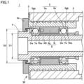
- Fig. 1 is a cross-sectional view showing a schematic construction of a spindle apparatus 1 including a bearing apparatus 30 according to the present embodiment.
- Spindle apparatus 1 shown in Fig. 1 is used, for example, as a built-in motor type spindle apparatus of a machine tool.
- a not-shown motor is incorporated on one end side (on the right side in Fig. 1 ) of a main spindle 4 supported by spindle apparatus 1 for a main spindle of a machine tool, and a not-shown cutting tool such as an end mill is connected to the other end (on the left side in Fig. 1 ).
- a diameter of main spindle 4 is set to 70 mm and a maximum rotation speed of main spindle 4 is set to 20000 rotations/minute.
- Spindle apparatus 1 includes bearing apparatus 30.
- Bearing apparatus 30 includes a bearing 5 including two bearings 5a and 5b and a spacer 6 arranged between bearings 5a and 5b.
- Main spindle 4 is provided in a cylindrical housing 3 embedded in an inside portion of a bearing jacket 2 and rotatably supported by bearings 5a and 5b.
- Bearing 5a is a rolling bearing including an inner ring 5ia made of a metal, an outer ring 5ga made of a metal, a plurality of rolling elements Ta arranged between inner ring 5ia and outer ring 5ga, and a retainer Rta.
- the plurality of rolling elements Ta are held at intervals by retainer Rta.
- Bearing 5b is a rolling bearing including an inner ring 5ib made of a metal, an outer ring 5gb made of a metal, a plurality of rolling elements Tb arranged between inner ring 5ib and outer ring 5gb, and a retainer Rtb.
- the plurality of rolling elements Tb are held at intervals by retainer Rtb.
- Inner ring 5ia of bearing 5a and inner ring 5ib of bearing 5b that are distant in an axial direction are fitted to main spindle 4 by interference fit (press-fitting).
- Spacer 6 includes an inner-ring spacer 6i and an outer-ring spacer 6g.
- Inner-ring spacer 6i is arranged between inner rings 5ia and 5ib and outer-ring spacer 6g is arranged between outer rings 5ga and 5gb.
- An angular contact ball bearing, a deep groove ball bearing, or a tapered roller bearing can be employed as bearings 5a and 5b.
- the angular contact ball bearing is included in bearing apparatus 30 shown in Fig. 1 , where two bearings 5a and 5b are provided in back-to-back duplex bearing (DB) arrangement.
- DB back-to-back duplex bearing
- Arrangement of the bearing is not limited to back-to-back duplex bearing arrangement, and for example, face-to-face duplex bearing arrangement may be applicable.
- a cooling medium flow channel is provided in housing 3. By feeding a cooling medium between housing 3 and bearing jacket 2, bearings 5a and 5b can be cooled.
- a communication module 140 containing a sensor is arranged between bearing 5a and bearing 5b. More specifically, communication module 140 is attached to outer-ring spacer 6g as being exposed at an end surface on a side of bearing 5a (on a side of the cutting tool) in the axial direction of outer-ring spacer 6g. A communication module similar to communication module 140 may be provided also in an end surface on a side of bearing 5b (a side of the motor) in the axial direction of outer-ring spacer 6g.
- Fig. 2 is a block diagram showing an exemplary configuration of communication module 140 according to the present embodiment.
- Communication module 140 contains a plurality of sensors (a heat flux sensor 11 that measures a heat flux, a temperature sensor 56 that measures a temperature, a vibration sensor 57 that measures vibration, and a load sensor 59 that measures preload) for controlling main spindle 4 or monitoring a state of bearing apparatus 30, a communication apparatus 141, and a power generation apparatus 142.
- sensors a heat flux sensor 11 that measures a heat flux
- a temperature sensor 56 that measures a temperature
- a vibration sensor 57 that measures vibration
- a load sensor 59 that measures preload
- Communication apparatus 141 is connected to each sensor through an electrical wire and collects data indicating a result of detection by each sensor.
- Communication apparatus 141 may wirelessly be connected to each sensor and wirelessly collect data indicating a result of detection by each sensor.
- Communication apparatus 141 transmits data collected from each sensor to an external apparatus 200 provided outside bearing apparatus 30 through wireless communication over electromagnetic waves.
- communication apparatus 141 is in conformity with communication standards of Bluetooth ® , and wirelessly transmits data indicating a result of detection by each sensor to external apparatus 200 over radio waves in a frequency band of 2.4 GHz.
- External apparatus 200 is assumed to be arranged at a position on an outer side (the left side of bearing 5a in Fig. 1 ) in the axial direction of bearing 5a. Therefore, bearing 5a is present between communication apparatus 141 and external apparatus 200.
- Power generation apparatus 142 is connected to communication apparatus 141 and self-generates electric power for driving communication apparatus 141.
- a thermoelectric element (Peltier element) that generates electric power based on a Seebeck effect can be employed as power generation apparatus 142.
- power generation apparatus 142 may supply electric power to that sensor.
- each sensor, communication apparatus 141, and power generation apparatus 142 are modularized into a single communication module 140 and arranged in outer-ring spacer 6g is described in the present embodiment, each sensor, communication apparatus 141, and power generation apparatus 142 may individually be arranged without being modularized.
- bearing apparatus 30 is constructed such that communication module 140 containing a plurality of sensors and communication apparatus 141 is arranged between bearing 5a and bearing 5b and wirelessly transmits data indicating a result of detection by each sensor to the outside.
- Inner ring 5ia and outer ring 5ga of bearing 5a are both made of a metal and radio waves are less likely to propagate therethrough. Furthermore, the plurality of rolling elements Ta arranged between inner ring 5ia and outer ring 5ga revolve as being in contact with inner ring 5ia and outer ring 5ga with rotation of inner ring 5ia. Therefore, if the plurality of rolling elements Ta are also made of a metal, passage of radio waves from communication module 140 to the outside of bearing 5a is difficult.
- an outer dimension D1 of inner ring 5ia of bearing 5a is set to be smaller than an inner dimension D2 of outer ring 5ga of bearing 5 a, so that a space is secured in a region lying between inner ring 5ia and outer ring 5ga.
- silicon nitride (Si 3 N 4 or the like) through which electromagnetic waves can pass is employed as a material for the plurality of rolling elements Ta arranged between inner ring 5ia and outer ring 5ga.
- a non-magnetic region required for passage of electromagnetic waves can thus be formed in a region lying between inner ring 5ia and outer ring 5ga of bearing 5a.
- data from communication module 140 can wirelessly be transmitted to the outside of bearing apparatus 30 through the non-magnetic region between inner ring 5ia and outer ring 5ga of bearing 5a.
- data can wirelessly be transmitted to the outside. Consequently, while interference with another mechanism around bearing 5a, poorer accuracy in shape of housing 3, or increase in cost is prevented, detection information from each sensor can wirelessly be transmitted to the outside of bearing apparatus 30.
- bearing apparatus 30 similarly to communication apparatus 141, power generation apparatus 142 that self-generates electric power for driving communication apparatus 141 is arranged between bearing 5a and bearing 5b. Therefore, communication apparatus 141 can be driven without an electrical wire for supply of drive power to communication apparatus 141 being provided on the outside of bearing apparatus 30.
- bearing 5b For wireless transmission of data also to the outside (the right side of bearing 5b in Fig. 1 ) in the axial direction of bearing 5b, bearing 5b should only be constructed similarly to bearing 5a. Specifically, the outer dimension of inner ring 5ib of bearing 5b should only be set to be smaller than the inner dimension of outer ring 5gb of bearing 5b to secure a space in a region lying between inner ring 5ib and outer ring 5gb, and then the plurality of rolling elements Tb arranged between inner ring 5ib and outer ring 5gb should only be made of silicon nitride.
- rolling element Ta or rolling element Tb should only be a non-magnetic material through which electromagnetic waves can pass, and is not limited to silicon nitride described above.
- rolling element Ta or rolling element Tb may be made of a ceramic material such as alumina or zirconia, a resin material such as polyether ether ketone (PEEK) or polyphenylene sulfide (PPS), a material reinforced with carbon fibers or glass fibers, glass, or rubber.
- PEEK polyether ether ketone
- PPS polyphenylene sulfide
- outer dimension D1 of inner ring 5ia of bearing 5 a may be equal to inner dimension D2 of outer ring 5ga of bearing 5a.
- the non-magnetic region is formed between inner ring 5ia and outer ring 5ga by setting outer dimension D1 of inner ring 5ia of bearing 5a to be smaller than inner dimension D2 of outer ring 5ga and making rolling element Ta of the non-magnetic material.
- the non-magnetic region is formed between inner ring 5ia and outer ring 5ga by setting a ratio occupied by the plurality of rolling elements Ta on a pitch circle circumference lying between inner ring 5ia and outer ring 5ga to be not lower than 40% and not higher than 90%.
- the construction is otherwise the same as in the embodiment described above.
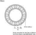
- Fig. 3 is a diagram showing an exemplary arrangement of rolling element Ta within bearing 5a according to the present first modification.
- the plurality of rolling elements Ta are held by retainer Rta as being arranged at prescribed intervals on the pitch circle circumference lying between inner ring 5ia and outer ring 5ga.
- Fig. 3 shows an example in which a ratio occupied by the plurality of rolling elements Ta on the pitch circle circumference is approximately 50%. While a load capacity of bearing 5a is secured by thus setting the ratio occupied by the plurality of rolling elements Ta on the pitch circle circumference to 50%, the non-magnetic region is formed by securing a space required for transmission of data between adjacent rolling elements Ta.
- the ratio occupied by the plurality of rolling elements Ta on the pitch circle circumference is desirably not lower than 40% and not higher than 90%.
- a range not lower than 50% in the range not lower than 40% and not higher than 90% is an optimal range within which the non-magnetic region is formed between adjacent rolling elements Ta while a sufficient load capacity of bearing 5a is secured.
- rolling element Ta can be made of a metal (magnetic material) instead of a non-magnetic material.
- rolling element Ta can be made of high-carbon chromium steel excellent in wear resistance. Transmission of radio waves may further be facilitated by making rolling element Ta of the non-magnetic material. At least half rolling elements Ta of the plurality of rolling elements Ta may be made of the magnetic material and remaining rolling elements Ta may be made of the non-magnetic material.
- Communication module 140 is in conformity with communication standards of Bluetooth ® , and transmits radio waves in a frequency band of 2.4 GHz.
- a frequency of revolution with respect to outer ring 5ga, of rolling elements Ta at the time when inner ring 5ia rotates at 20000 rotations/minute which is a maximum rotation speed of main spindle 4 is approximately from 100 to 150 Hz, and a frequency of transmitted radio waves is sufficiently higher than the frequency of revolution of rolling elements Ta. Therefore, radio waves from communication module 140 can sufficiently pass between rolling elements Ta also during rotation of inner ring 5ia.
- the non-magnetic region may be formed between inner ring 5ia and outer ring 5ga by setting outer dimension D1 of inner ring 5ia of bearing 5a to be smaller than inner dimension D2 of outer ring 5ga while setting the ratio occupied by the plurality of rolling elements Ta on the pitch circle circumference lying between inner ring 5ia and outer ring 5ga to be not lower than 40% and not higher than 90%.
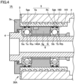
- Fig. 4 is a cross-sectional view showing a schematic construction of a spindle apparatus 1A including a bearing apparatus 30A according to the present second modification.
- Bearing apparatus 30A is a bearing apparatus resulting from change of communication module 140 in bearing apparatus 30 shown in Fig. 1 described above to a communication module 140A and addition of an O-ring 160 made of a non-magnetic material.
- Spindle apparatus 1A and bearing apparatus 30A are otherwise the same in construction to spindle apparatus 1 and bearing apparatus 30 described above, respectively.
- Communication module 140A is attached to outer-ring spacer 6g as being exposed at an outside surface of outer-ring spacer 6g.
- Communication module 140A is the same in basic configuration to communication module 140 described above.
- annular O-ring 160 made of a non-magnetic material is attached to circumferential groove 161.
- O-ring 160 should only be made of a non-magnetic material such as nitrile rubber or a resin.
- the non-magnetic region required for wireless transmission of data can be formed not only in the region between inner ring 5ia and outer ring 5ga of bearing 5a but also in a region between the outside surfaces of outer rings 5ga and 5gb of bearings 5a and 5b and an inside surface of housing 3.
- data from communication module 140A can wirelessly be transmitted to the outside of bearing apparatus 30A through the non-magnetic region formed in the region between inner ring 5ia and outer ring 5ga of bearing 5a and the non-magnetic region formed in the region between the outside surface of outer ring 5ga of bearing 5a and the inside surface of housing 3.
- the non-magnetic region is formed by providing O-ring 160 in the region between the outside surface of outer ring 5ga of bearing 5a and the inside surface of housing 3. Therefore, the region between inner ring 5ia and outer ring 5ga of bearing 5a does not necessarily have to be the non-magnetic region.
- rolling element Ta of bearing 5a may be made of a magnetic material such as a metal.
- Fig. 5 is a cross-sectional view showing a schematic construction of a spindle apparatus 1B including a bearing apparatus 30B according to the present third modification.
- Bearing apparatus 30B is a bearing apparatus resulting from addition of a band 162 instead of O-ring 160 in bearing apparatus 30A shown in Fig. 4 described above.
- Spindle apparatus 1B and bearing apparatus 30B are otherwise the same in construction to spindle apparatus 1 and bearing apparatus 30 described above, respectively.
- Portions in the inside surface of housing 3 where outer ring 5ga of bearing 5a and outer ring 5gb of bearing 5b are fitted are each provided with two circumferential grooves 163 extending in the circumferential direction in parallel.
- Annular band 162 made of a non-magnetic material is attached to circumferential groove 163.
- Band 162 should only be made of a non-magnetic material such as nitrile rubber or a resin.
- the non-magnetic region required for wireless transmission of data can be formed not only in the region between inner ring 5ia and outer ring 5ga of bearing 5a but also in the region between the outside surfaces of outer rings 5ga and 5gb of bearings 5a and 5b and the inside surface of housing 3.
- the non-magnetic region is formed in the region between the outside surface of outer ring 5ga of bearing 5a and the inside surface of housing 3. Therefore, the region between inner ring 5ia and outer ring 5ga of bearing 5a does not necessarily have to be the non-magnetic region.
- rolling element Ta of bearing 5a may be made of a magnetic material such as a metal.
- a component to be arranged between the outside surfaces of outer rings 5ga and 5gb of bearings 5a and 5b and the inside surface of housing 3 is not limited to an annular component such as O-ring 160 in the second modification described above or band 162 in the third modification.
- the space required for transmission of data may be secured, for example, by arranging a component in a strip shape or a component in a slip shape between the outside surface of the outer ring and the inside surface of the housing.
- 1 spindle apparatus 1 spindle apparatus; 2 bearing jacket; 3 housing; 4 main spindle; 5, 5a, 5b bearing; 5ga, 5gb outer ring; 5ia, 5ib inner ring; 6 spacer; 6g outer-ring spacer; 6i inner-ring spacer; 11 heat flux sensor; 30, 30A, 30B bearing apparatus; 56 temperature sensor; 57 vibration sensor; 59 load sensor; 140, 140A communication module, 141 communication apparatus; 142 power generation apparatus; 160 O-ring; 161, 163 circumferential groove; 162 band; 200 external apparatus; Rta, Rtb retainer; Ta, Tb rolling element
Landscapes
- Engineering & Computer Science (AREA)
- General Engineering & Computer Science (AREA)
- Mechanical Engineering (AREA)
- Ceramic Engineering (AREA)
- Rolling Contact Bearings (AREA)
- Arrangements For Transmission Of Measured Signals (AREA)
- Turning (AREA)
- Mounting Of Bearings Or Others (AREA)
- Computer Networks & Wireless Communication (AREA)
- Physics & Mathematics (AREA)
- General Physics & Mathematics (AREA)
Abstract
Description
- This invention relates to a bearing apparatus including a wireless communication function.
- To a machine including a rolling mechanism or a swing mechanism employed in a main spindle or the like of a machine tool, in order to control the machine or to monitor a state of the machine, a detection device such as a sensor may be attached.
- In particular, in the machine including a rolling bearing, it is effective to detect characteristics in the vicinity of the bearing in the inside of the machine. Therefore, various sensors such as a rotation sensor and a temperature sensor are desirably arranged in the vicinity of the bearing in the inside of the machine.
- Electrical wires have conventionally often been used for transmission of data detected by the sensors. Arrangement of electrical wires in the inside of the machine, however, may cause interference with another mechanism in the inside of the machine or lowering in function of that mechanism (for example, lowering in dimension accuracy or shape). Ease in assembly of the machine also becomes poor, which may also be a factor for lowering in productivity.
- In order to address the problems as above, for example,
Japanese Patent Laying-Open No. 2003-28151 - PTL 1:
Japanese Patent Laying-Open No. 2003-28151 - As described above, in the bearing apparatus disclosed in
Japanese Patent Laying-Open No. 2003-28151 - In the housing around the bearing, however, another mechanism for cooling the bearing is normally provided. When interference with another mechanism occurs, a sufficient space may not be provided in the housing. When a space in a complicated shape is provided in the housing in order to avoid interference with another mechanism, there is a concern about poor accuracy in shape of the housing or increase in cost.
- The present disclosure was made to solve the problems above, and an object thereof is to provide a bearing apparatus capable of wirelessly transmitting data to the outside without providing a space for facilitating propagation of radio waves in a component around a bearing.
-
- (1) A bearing apparatus according to the present disclosure is accommodated in the inside of a cylindrical housing. The bearing apparatus includes a first bearing including an inner ring, an outer ring, and a plurality of rolling elements arranged between the inner ring and the outer ring, and a communication apparatus arranged between the first bearing and a second bearing different from the first bearing, the communication apparatus wirelessly communicating over electromagnetic waves. A non-magnetic region for passage of the electromagnetic waves is formed in any region between an inside surface of the housing and the inner ring.
- (2) In one aspect, a self-generation apparatus arranged between the first bearing and the second bearing, the self-generation apparatus supplying electric power to the communication apparatus, is further provided.
- (3) In one aspect, an outer diameter of the inner ring is formed to be equal to or smaller than an inner diameter of the outer ring. The non-magnetic region is formed in a region between the inner ring and the outer ring.
- (4) In one aspect, the plurality of rolling elements are arranged at prescribed intervals from one another on a pitch circle circumference lying between the inner ring and the outer ring. A ratio occupied by the plurality of rolling elements on the pitch circle circumference is not lower than 40% and not higher than 90%.
- (5) In one aspect, the plurality of rolling elements are made of a non-magnetic material.
- (6) In one aspect, the non-magnetic material is silicon nitride.
- (7) In one aspect, the plurality of rolling elements are made of a magnetic material.
- (8) In one aspect, the magnetic material is high-carbon chromium steel.
- (9) In one aspect, the bearing apparatus further includes a component arranged between an outside surface of the outer ring and the inside surface of the housing, the component being made of a non-magnetic material. The non-magnetic region is formed in a region between the outside surface of the outer ring and the inside surface of the housing.
- (10) In one aspect, the communication apparatus wirelessly communicates over electromagnetic waves at a frequency higher than a revolution period of the rolling elements in rotation of the first bearing.
- According to the present disclosure, a bearing apparatus capable of wirelessly transmitting data to the outside without a space for facilitating propagation of radio waves in a component around a bearing can be provided.
-
-
Fig. 1 is a cross-sectional view (No. 1) showing a schematic construction of a spindle apparatus including a bearing apparatus. -
Fig. 2 is a block diagram showing an exemplary configuration of a communication module. -
Fig. 3 is a diagram showing an exemplary arrangement of a rolling element within a bearing. -
Fig. 4 is a cross-sectional view (No. 2) showing a schematic construction of a spindle apparatus including a bearing apparatus. -
Fig. 5 is a cross-sectional view (No. 3) showing a schematic construction of a spindle apparatus including a bearing apparatus. - An embodiment of the present disclosure will be described below with reference to the drawings. The same or corresponding elements in the drawings below have the same reference characters allotted and description thereof will not be repeated.
-
Fig. 1 is a cross-sectional view showing a schematic construction of aspindle apparatus 1 including abearing apparatus 30 according to the present embodiment. -
Spindle apparatus 1 shown inFig. 1 is used, for example, as a built-in motor type spindle apparatus of a machine tool. In this case, a not-shown motor is incorporated on one end side (on the right side inFig. 1 ) of amain spindle 4 supported byspindle apparatus 1 for a main spindle of a machine tool, and a not-shown cutting tool such as an end mill is connected to the other end (on the left side inFig. 1 ). In the present embodiment, a diameter ofmain spindle 4 is set to 70 mm and a maximum rotation speed ofmain spindle 4 is set to 20000 rotations/minute. -
Spindle apparatus 1 includesbearing apparatus 30.Bearing apparatus 30 includes abearing 5 including twobearings spacer 6 arranged betweenbearings Main spindle 4 is provided in acylindrical housing 3 embedded in an inside portion of abearing jacket 2 and rotatably supported bybearings -
Bearing 5a is a rolling bearing including an inner ring 5ia made of a metal, an outer ring 5ga made of a metal, a plurality of rolling elements Ta arranged between inner ring 5ia and outer ring 5ga, and a retainer Rta. The plurality of rolling elements Ta are held at intervals by retainer Rta. -
Bearing 5b is a rolling bearing including an inner ring 5ib made of a metal, an outer ring 5gb made of a metal, a plurality of rolling elements Tb arranged between inner ring 5ib and outer ring 5gb, and a retainer Rtb. The plurality of rolling elements Tb are held at intervals by retainer Rtb. - Inner ring 5ia of bearing 5a and inner ring 5ib of bearing 5b that are distant in an axial direction are fitted to
main spindle 4 by interference fit (press-fitting). -
Spacer 6 includes an inner-ring spacer 6i and an outer-ring spacer 6g. Inner-ring spacer 6i is arranged between inner rings 5ia and 5ib and outer-ring spacer 6g is arranged between outer rings 5ga and 5gb. - An angular contact ball bearing, a deep groove ball bearing, or a tapered roller bearing can be employed as
bearings bearing apparatus 30 shown inFig. 1 , where twobearings - Though a structure in which two
bearings main spindle 4 is illustrated and described, a structure in which two or more bearings supportmain spindle 4 may be applicable. - A cooling medium flow channel is provided in
housing 3. By feeding a cooling medium betweenhousing 3 and bearingjacket 2,bearings - A
communication module 140 containing a sensor is arranged betweenbearing 5a andbearing 5b. More specifically,communication module 140 is attached to outer-ring spacer 6g as being exposed at an end surface on a side of bearing 5a (on a side of the cutting tool) in the axial direction of outer-ring spacer 6g. A communication module similar tocommunication module 140 may be provided also in an end surface on a side of bearing 5b (a side of the motor) in the axial direction of outer-ring spacer 6g. -
Fig. 2 is a block diagram showing an exemplary configuration ofcommunication module 140 according to the present embodiment.Communication module 140 contains a plurality of sensors (aheat flux sensor 11 that measures a heat flux, atemperature sensor 56 that measures a temperature, avibration sensor 57 that measures vibration, and aload sensor 59 that measures preload) for controllingmain spindle 4 or monitoring a state of bearingapparatus 30, acommunication apparatus 141, and apower generation apparatus 142. -
Communication apparatus 141 is connected to each sensor through an electrical wire and collects data indicating a result of detection by each sensor.Communication apparatus 141 may wirelessly be connected to each sensor and wirelessly collect data indicating a result of detection by each sensor. -
Communication apparatus 141 transmits data collected from each sensor to anexternal apparatus 200 provided outsidebearing apparatus 30 through wireless communication over electromagnetic waves. In the present embodiment,communication apparatus 141 is in conformity with communication standards of Bluetooth®, and wirelessly transmits data indicating a result of detection by each sensor toexternal apparatus 200 over radio waves in a frequency band of 2.4 GHz.External apparatus 200 is assumed to be arranged at a position on an outer side (the left side of bearing 5a inFig. 1 ) in the axial direction of bearing 5a. Therefore, bearing 5a is present betweencommunication apparatus 141 andexternal apparatus 200. -
Power generation apparatus 142 is connected tocommunication apparatus 141 and self-generates electric power for drivingcommunication apparatus 141. For example, a thermoelectric element (Peltier element) that generates electric power based on a Seebeck effect can be employed aspower generation apparatus 142. When electric power is required for driving each sensor,power generation apparatus 142 may supply electric power to that sensor. - Though an example in which each sensor,
communication apparatus 141, andpower generation apparatus 142 are modularized into asingle communication module 140 and arranged in outer-ring spacer 6g is described in the present embodiment, each sensor,communication apparatus 141, andpower generation apparatus 142 may individually be arranged without being modularized. - As described above, bearing
apparatus 30 according to the present embodiment is constructed such thatcommunication module 140 containing a plurality of sensors andcommunication apparatus 141 is arranged betweenbearing 5a andbearing 5b and wirelessly transmits data indicating a result of detection by each sensor to the outside. - Inner ring 5ia and outer ring 5ga of bearing 5a, however, are both made of a metal and radio waves are less likely to propagate therethrough. Furthermore, the plurality of rolling elements Ta arranged between inner ring 5ia and outer ring 5ga revolve as being in contact with inner ring 5ia and outer ring 5ga with rotation of inner ring 5ia. Therefore, if the plurality of rolling elements Ta are also made of a metal, passage of radio waves from
communication module 140 to the outside of bearing 5a is difficult. - If a space for facilitating propagation of radio waves to a portion of
housing 3 around bearing 5a is provided in a radial direction, interference with a cooling medium flow channel inhousing 3 and additionally poorer accuracy in shape ofhousing 3 and increase in cost may disadvantageously be caused. - In view of such a disadvantage, in bearing
apparatus 30 according to the present embodiment, as shown inFig. 1 , an outer dimension D1 of inner ring 5ia of bearing 5a is set to be smaller than an inner dimension D2 of outer ring 5ga of bearing 5 a, so that a space is secured in a region lying between inner ring 5ia and outer ring 5ga. Then, silicon nitride (Si3N4 or the like) through which electromagnetic waves can pass is employed as a material for the plurality of rolling elements Ta arranged between inner ring 5ia and outer ring 5ga. A non-magnetic region required for passage of electromagnetic waves can thus be formed in a region lying between inner ring 5ia and outer ring 5ga of bearing 5a. - Thus, in bearing
apparatus 30 according to the present embodiment, data fromcommunication module 140 can wirelessly be transmitted to the outside of bearingapparatus 30 through the non-magnetic region between inner ring 5ia and outer ring 5ga of bearing 5a. Thus, without providing a space for facilitating propagation of radio waves in a component such ashousing 3 arranged around bearing 5a, data can wirelessly be transmitted to the outside. Consequently, while interference with another mechanism around bearing 5a, poorer accuracy in shape ofhousing 3, or increase in cost is prevented, detection information from each sensor can wirelessly be transmitted to the outside of bearingapparatus 30. - Furthermore, in bearing
apparatus 30 according to the present embodiment, similarly tocommunication apparatus 141,power generation apparatus 142 that self-generates electric power for drivingcommunication apparatus 141 is arranged betweenbearing 5a andbearing 5b. Therefore,communication apparatus 141 can be driven without an electrical wire for supply of drive power tocommunication apparatus 141 being provided on the outside of bearingapparatus 30. - For wireless transmission of data also to the outside (the right side of bearing 5b in
Fig. 1 ) in the axial direction of bearing 5b, bearing 5b should only be constructed similarly to bearing 5a. Specifically, the outer dimension of inner ring 5ib of bearing 5b should only be set to be smaller than the inner dimension of outer ring 5gb of bearing 5b to secure a space in a region lying between inner ring 5ib and outer ring 5gb, and then the plurality of rolling elements Tb arranged between inner ring 5ib and outer ring 5gb should only be made of silicon nitride. - The material for rolling element Ta or rolling element Tb should only be a non-magnetic material through which electromagnetic waves can pass, and is not limited to silicon nitride described above. For example, rolling element Ta or rolling element Tb may be made of a ceramic material such as alumina or zirconia, a resin material such as polyether ether ketone (PEEK) or polyphenylene sulfide (PPS), a material reinforced with carbon fibers or glass fibers, glass, or rubber.
- So long as the non-magnetic region is secured in the space between inner ring 5ia and outer ring 5ga of bearing 5a by making the plurality of rolling elements Ta of the non-magnetic material, outer dimension D1 of inner ring 5ia of bearing 5 a may be equal to inner dimension D2 of outer ring 5ga of bearing 5a.
- In the embodiment described above, the non-magnetic region is formed between inner ring 5ia and outer ring 5ga by setting outer dimension D1 of inner ring 5ia of bearing 5a to be smaller than inner dimension D2 of outer ring 5ga and making rolling element Ta of the non-magnetic material.
- In contrast, in the present second modification, while outer dimension D1 of inner ring 5ia of bearing 5a is set to be smaller than inner dimension D2 of outer ring 5ga as in the embodiment described above, the non-magnetic region is formed between inner ring 5ia and outer ring 5ga by setting a ratio occupied by the plurality of rolling elements Ta on a pitch circle circumference lying between inner ring 5ia and outer ring 5ga to be not lower than 40% and not higher than 90%. The construction is otherwise the same as in the embodiment described above.
-
Fig. 3 is a diagram showing an exemplary arrangement of rolling element Ta within bearing 5a according to the present first modification. The plurality of rolling elements Ta are held by retainer Rta as being arranged at prescribed intervals on the pitch circle circumference lying between inner ring 5ia and outer ring 5ga. -
Fig. 3 shows an example in which a ratio occupied by the plurality of rolling elements Ta on the pitch circle circumference is approximately 50%. While a load capacity of bearing 5a is secured by thus setting the ratio occupied by the plurality of rolling elements Ta on the pitch circle circumference to 50%, the non-magnetic region is formed by securing a space required for transmission of data between adjacent rolling elements Ta. - When the ratio occupied by the plurality of rolling elements Ta on the pitch circle circumference is lower than 40%, the load capacity of bearing 5a may be insufficient. When the ratio occupied by the plurality of rolling elements Ta on the pitch circle circumference exceeds 90%, the space required for wireless transmission of data cannot be secured between adjacent rolling elements Ta and the non-magnetic region cannot be formed. Therefore, the ratio occupied by the plurality of rolling elements Ta on the pitch circle circumference is desirably not lower than 40% and not higher than 90%. In particular, a range not lower than 50% in the range not lower than 40% and not higher than 90% is an optimal range within which the non-magnetic region is formed between adjacent rolling elements Ta while a sufficient load capacity of bearing 5a is secured.
- When the ratio occupied by the plurality of rolling elements Ta on the pitch circle circumference is not lower than 40% and not higher than 90%, the space required for wireless transmission of data is secured between adjacent rolling elements Ta. Therefore, rolling element Ta can be made of a metal (magnetic material) instead of a non-magnetic material. For example, rolling element Ta can be made of high-carbon chromium steel excellent in wear resistance. Transmission of radio waves may further be facilitated by making rolling element Ta of the non-magnetic material. At least half rolling elements Ta of the plurality of rolling elements Ta may be made of the magnetic material and remaining rolling elements Ta may be made of the non-magnetic material.
-
Communication module 140 is in conformity with communication standards of Bluetooth®, and transmits radio waves in a frequency band of 2.4 GHz. A frequency of revolution with respect to outer ring 5ga, of rolling elements Ta at the time when inner ring 5ia rotates at 20000 rotations/minute which is a maximum rotation speed ofmain spindle 4 is approximately from 100 to 150 Hz, and a frequency of transmitted radio waves is sufficiently higher than the frequency of revolution of rolling elements Ta. Therefore, radio waves fromcommunication module 140 can sufficiently pass between rolling elements Ta also during rotation of inner ring 5ia. - As set forth above, the non-magnetic region may be formed between inner ring 5ia and outer ring 5ga by setting outer dimension D1 of inner ring 5ia of bearing 5a to be smaller than inner dimension D2 of outer ring 5ga while setting the ratio occupied by the plurality of rolling elements Ta on the pitch circle circumference lying between inner ring 5ia and outer ring 5ga to be not lower than 40% and not higher than 90%.
-
Fig. 4 is a cross-sectional view showing a schematic construction of aspindle apparatus 1A including abearing apparatus 30A according to the present second modification.Bearing apparatus 30A is a bearing apparatus resulting from change ofcommunication module 140 in bearingapparatus 30 shown inFig. 1 described above to acommunication module 140A and addition of an O-ring 160 made of a non-magnetic material.Spindle apparatus 1A andbearing apparatus 30A are otherwise the same in construction tospindle apparatus 1 and bearingapparatus 30 described above, respectively. -
Communication module 140A is attached to outer-ring spacer 6g as being exposed at an outside surface of outer-ring spacer 6g.Communication module 140A is the same in basic configuration tocommunication module 140 described above. - In each of an outside surface of outer ring 5ga of bearing 5a and an outside surface of outer ring 5gb of bearing 5b, two
circumferential grooves 161 extending in a circumferential direction are provided in parallel. Annular O-ring 160 made of a non-magnetic material is attached tocircumferential groove 161. O-ring 160 should only be made of a non-magnetic material such as nitrile rubber or a resin. - By inserting
such bearing apparatus 30A intohousing 3, the non-magnetic region required for wireless transmission of data can be formed not only in the region between inner ring 5ia and outer ring 5ga of bearing 5a but also in a region between the outside surfaces of outer rings 5ga and 5gb ofbearings housing 3. - Thus, in bearing
apparatus 30A according to the present second modification, data fromcommunication module 140A can wirelessly be transmitted to the outside of bearingapparatus 30A through the non-magnetic region formed in the region between inner ring 5ia and outer ring 5ga of bearing 5a and the non-magnetic region formed in the region between the outside surface of outer ring 5ga of bearing 5a and the inside surface ofhousing 3. - In
bearing apparatus 30A according to the present second modification, the non-magnetic region is formed by providing O-ring 160 in the region between the outside surface of outer ring 5ga of bearing 5a and the inside surface ofhousing 3. Therefore, the region between inner ring 5ia and outer ring 5ga of bearing 5a does not necessarily have to be the non-magnetic region. In other words, in bearingapparatus 30A, rolling element Ta of bearing 5a may be made of a magnetic material such as a metal. -
Fig. 5 is a cross-sectional view showing a schematic construction of aspindle apparatus 1B including abearing apparatus 30B according to the present third modification.Bearing apparatus 30B is a bearing apparatus resulting from addition of aband 162 instead of O-ring 160 in bearingapparatus 30A shown inFig. 4 described above.Spindle apparatus 1B andbearing apparatus 30B are otherwise the same in construction tospindle apparatus 1 and bearingapparatus 30 described above, respectively. - Portions in the inside surface of
housing 3 where outer ring 5ga of bearing 5a and outer ring 5gb of bearing 5b are fitted are each provided with twocircumferential grooves 163 extending in the circumferential direction in parallel.Annular band 162 made of a non-magnetic material is attached tocircumferential groove 163. Band 162 should only be made of a non-magnetic material such as nitrile rubber or a resin. - In
bearing apparatus 30B according to the present third modification as well, as in bearingapparatus 30A according to the second modification described above, the non-magnetic region required for wireless transmission of data can be formed not only in the region between inner ring 5ia and outer ring 5ga of bearing 5a but also in the region between the outside surfaces of outer rings 5ga and 5gb ofbearings housing 3. - In
bearing apparatus 30B according to the present third modification as well, as in bearingapparatus 30A according to the second modification described above, the non-magnetic region is formed in the region between the outside surface of outer ring 5ga of bearing 5a and the inside surface ofhousing 3. Therefore, the region between inner ring 5ia and outer ring 5ga of bearing 5a does not necessarily have to be the non-magnetic region. In other words, in bearingapparatus 30B, rolling element Ta of bearing 5a may be made of a magnetic material such as a metal. - A component to be arranged between the outside surfaces of outer rings 5ga and 5gb of
bearings housing 3 is not limited to an annular component such as O-ring 160 in the second modification described above orband 162 in the third modification. The space required for transmission of data may be secured, for example, by arranging a component in a strip shape or a component in a slip shape between the outside surface of the outer ring and the inside surface of the housing. - It should be understood that the embodiment disclosed herein is illustrative and non-restrictive in every respect. The scope of the present disclosure is defined by the terms of the claims rather than the description of the embodiment above and is intended to include any modifications within the scope and meaning equivalent to the terms of the claims.
- 1 spindle apparatus; 2 bearing jacket; 3 housing; 4 main spindle; 5, 5a, 5b bearing; 5ga, 5gb outer ring; 5ia, 5ib inner ring; 6 spacer; 6g outer-ring spacer; 6i inner-ring spacer; 11 heat flux sensor; 30, 30A, 30B bearing apparatus; 56 temperature sensor; 57 vibration sensor; 59 load sensor; 140, 140A communication module, 141 communication apparatus; 142 power generation apparatus; 160 O-ring; 161, 163 circumferential groove; 162 band; 200 external apparatus; Rta, Rtb retainer; Ta, Tb rolling element
Claims (10)
- A bearing apparatus accommodated in inside of a cylindrical housing, the bearing apparatus comprising:a first bearing including an inner ring, an outer ring, and a plurality of rolling elements arranged between the inner ring and the outer ring; anda communication apparatus arranged between the first bearing and a second bearing different from the first bearing, the communication apparatus wirelessly communicating over electromagnetic waves, whereina non-magnetic region for passage of the electromagnetic waves is formed in any region between an inside surface of the housing and the inner ring.
- The bearing apparatus according to claim 1, further comprising a self-generation apparatus arranged between the first bearing and the second bearing, the self-generation apparatus supplying electric power to the communication apparatus.
- The bearing apparatus according to claim 1, whereinan outer diameter of the inner ring is formed to be equal to or smaller than an inner diameter of the outer ring, andthe non-magnetic region is formed in a region lying between the inner ring and the outer ring.
- The bearing apparatus according to any one of claims 1 to 3, whereinthe plurality of rolling elements are arranged at prescribed intervals from one another on a pitch circle circumference lying between the inner ring and the outer ring, anda ratio occupied by the plurality of rolling elements on the pitch circle circumference is not lower than 40% and not higher than 90%.
- The bearing apparatus according to claim 3 or 4, wherein
the plurality of rolling elements are made of a non-magnetic material. - The bearing apparatus according to claim 5, wherein
the non-magnetic material is silicon nitride. - The bearing apparatus according to claim 3 or 4, wherein
the plurality of rolling elements are made of a magnetic material. - The bearing apparatus according to claim 7, wherein
the magnetic material is high-carbon chromium steel. - The bearing apparatus according to any one of claims 1 to 8, further comprising a component arranged between an outside surface of the outer ring and the inside surface of the housing, the component being made of a non-magnetic material, wherein
the non-magnetic region is formed in a region lying between the outside surface of the outer ring and the inside surface of the housing. - The bearing apparatus according to any one of claims 1 to 9, wherein
the communication apparatus wirelessly communicates over electromagnetic waves at a frequency higher than a revolution period of the rolling elements in rotation of the first bearing at an allowable rotation speed.
Applications Claiming Priority (2)
| Application Number | Priority Date | Filing Date | Title |
|---|---|---|---|
| JP2020126143A JP7553276B2 (en) | 2020-07-27 | 2020-07-27 | Bearing device |
| PCT/JP2021/027286 WO2022024910A1 (en) | 2020-07-27 | 2021-07-21 | Bearing device |
Publications (2)
| Publication Number | Publication Date |
|---|---|
| EP4191083A1 true EP4191083A1 (en) | 2023-06-07 |
| EP4191083A4 EP4191083A4 (en) | 2024-07-31 |
Family
ID=80035581
Family Applications (1)
| Application Number | Title | Priority Date | Filing Date |
|---|---|---|---|
| EP21848576.1A Pending EP4191083A4 (en) | 2020-07-27 | 2021-07-21 | STORAGE DEVICE |
Country Status (6)
| Country | Link |
|---|---|
| US (1) | US20230250850A1 (en) |
| EP (1) | EP4191083A4 (en) |
| JP (2) | JP7553276B2 (en) |
| KR (1) | KR20230042476A (en) |
| CN (1) | CN116134231A (en) |
| WO (1) | WO2022024910A1 (en) |
Families Citing this family (1)
| Publication number | Priority date | Publication date | Assignee | Title |
|---|---|---|---|---|
| JP2025149074A (en) * | 2024-03-26 | 2025-10-08 | Ntn株式会社 | Bearing device with strain sensor, outer ring spacer with strain sensor, and spindle device for machine tool |
Family Cites Families (33)
| Publication number | Priority date | Publication date | Assignee | Title |
|---|---|---|---|---|
| JPH078913Y2 (en) * | 1988-03-22 | 1995-03-06 | 株式会社不二越 | Rolling bearing creep prevention device |
| US6023961A (en) * | 1998-04-02 | 2000-02-15 | Reliance Electric Industrial Company | Micro-viscosity sensor and lubrication analysis system employing the same |
| US6857786B2 (en) * | 2000-02-01 | 2005-02-22 | Frank Victor Csik | Constant velocity joint integrated to wheel bearing and to axially adjustable hub |
| US6535135B1 (en) * | 2000-06-23 | 2003-03-18 | The Timken Company | Bearing with wireless self-powered sensor unit |
| DE10048192C2 (en) * | 2000-09-28 | 2003-06-18 | Siemens Ag | Use of a roller bearing for an MRI scanner |
| JP2003042151A (en) * | 2001-02-22 | 2003-02-13 | Nsk Ltd | Rolling bearing device and sensor-equipped ring of the bearing device |
| JP2003028151A (en) | 2001-07-11 | 2003-01-29 | Nsk Ltd | Bearing device with wireless sensor |
| US7034711B2 (en) * | 2001-08-07 | 2006-04-25 | Nsk Ltd. | Wireless sensor, rolling bearing with sensor, management apparatus and monitoring system |
| JP4423851B2 (en) * | 2002-02-28 | 2010-03-03 | 日本精工株式会社 | Method for manufacturing linear motion guide device |
| CA2399779C (en) * | 2002-08-26 | 2008-01-08 | Darryl D. Krochak | Thrust bearing |
| JP2004204913A (en) * | 2002-12-24 | 2004-07-22 | Nsk Ltd | Bearing device |
| JP2005177908A (en) | 2003-12-18 | 2005-07-07 | Nsk Ltd | Spindle device |
| JP2005214262A (en) * | 2004-01-28 | 2005-08-11 | Koyo Seiko Co Ltd | Obliquely contact ball bearing |
| JP2008032070A (en) | 2006-07-27 | 2008-02-14 | Ntn Corp | Ball bearing |
| JP2008082797A (en) | 2006-09-27 | 2008-04-10 | Nsk Ltd | Bearing device |
| WO2008084835A1 (en) * | 2007-01-11 | 2008-07-17 | Nsk Ltd. | Rolling bearing |
| JP2008286219A (en) * | 2007-05-15 | 2008-11-27 | Ntn Corp | Bearing device and bearing preload detecting device |
| JP5564963B2 (en) * | 2009-02-19 | 2014-08-06 | 日本精工株式会社 | Bearing device and spindle device of machine tool |
| US8695564B2 (en) * | 2010-02-04 | 2014-04-15 | Dalhousie University | Toroidal engine |
| JP5442553B2 (en) * | 2010-07-21 | 2014-03-12 | 日立建機株式会社 | Bearing damage detection method |
| JP2012167814A (en) | 2011-01-25 | 2012-09-06 | Nsk Ltd | Rolling bearing |
| AU2012276745A1 (en) * | 2011-06-29 | 2013-12-19 | Ntn Corporation | Conveyor device bearing unit with malfunction detection function, conveyor equipment and bearing unit monitoring system |
| WO2013014954A1 (en) * | 2011-07-27 | 2013-01-31 | 日本精工株式会社 | Roller bearing for hard disk actuators |
| DE102013006966A1 (en) * | 2013-04-23 | 2014-10-23 | Robert Bosch Gmbh | Measuring device arrangement for measuring a bearing preload force of a roller bearing pair |
| JP5626708B2 (en) | 2013-06-04 | 2014-11-19 | 日本精工株式会社 | Bearing device |
| FR3018569B1 (en) * | 2014-03-11 | 2016-12-09 | Skf Ab | INSTRUMENT BEARING AND METHOD OF MANUFACTURING SUCH AN INSTRUMENT BEARING |
| JP2016142401A (en) | 2015-02-05 | 2016-08-08 | Ntn株式会社 | Bearing for main electric motor, support structure of main electric motor spindle and main electric motor of railway vehicle |
| JP6368271B2 (en) | 2015-04-06 | 2018-08-01 | Ntn株式会社 | Manufacturing method of rolling bearing |
| US10138942B2 (en) * | 2017-01-11 | 2018-11-27 | Aurora Flight Sciences Corporation | Passive fault-tolerant shaft seal configuration |
| JP7074505B2 (en) | 2018-03-05 | 2022-05-24 | Ntn株式会社 | Bearing equipment |
| JP7136637B2 (en) | 2018-09-10 | 2022-09-13 | ミネベアミツミ株式会社 | rolling bearing |
| JP2020060227A (en) | 2018-10-09 | 2020-04-16 | Ntn株式会社 | Bearing device |
| JP7654370B2 (en) * | 2020-09-15 | 2025-04-01 | Ntn株式会社 | Bearing device |
-
2020
- 2020-07-27 JP JP2020126143A patent/JP7553276B2/en active Active
-
2021
- 2021-07-21 WO PCT/JP2021/027286 patent/WO2022024910A1/en not_active Ceased
- 2021-07-21 EP EP21848576.1A patent/EP4191083A4/en active Pending
- 2021-07-21 KR KR1020237004421A patent/KR20230042476A/en active Pending
- 2021-07-21 CN CN202180060174.5A patent/CN116134231A/en active Pending
- 2021-07-21 US US18/012,802 patent/US20230250850A1/en active Pending
-
2024
- 2024-09-05 JP JP2024152823A patent/JP7720972B2/en active Active
Also Published As
| Publication number | Publication date |
|---|---|
| US20230250850A1 (en) | 2023-08-10 |
| JP7720972B2 (en) | 2025-08-08 |
| WO2022024910A1 (en) | 2022-02-03 |
| JP7553276B2 (en) | 2024-09-18 |
| CN116134231A (en) | 2023-05-16 |
| TW202210740A (en) | 2022-03-16 |
| KR20230042476A (en) | 2023-03-28 |
| JP2022023304A (en) | 2022-02-08 |
| JP2024161229A (en) | 2024-11-15 |
| EP4191083A4 (en) | 2024-07-31 |
Similar Documents
| Publication | Publication Date | Title |
|---|---|---|
| EP4215770B1 (en) | Bearing apparatus | |
| KR101428829B1 (en) | Sen style bearing unit | |
| EP4106149B1 (en) | Bearing device, and manufacturing method | |
| JP2019138464A (en) | Bearing device and spindle device | |
| JP2014238415A (en) | Bearing device and spindle device of machine tool | |
| JP2003042151A (en) | Rolling bearing device and sensor-equipped ring of the bearing device | |
| JP7720972B2 (en) | Bearing device | |
| GB2542266A (en) | Bearing arrangement having a sensor rolling element | |
| JP2003307435A (en) | Bearing device with sensor | |
| TWI916383B (en) | Bearing assembly | |
| CN120608924A (en) | Self-contained bearing and wireless power transmission device | |
| EP1961585B1 (en) | Bearing apparatus for axle and method of manufacturing the same | |
| JP2020003027A (en) | Bearing device | |
| WO2019159838A1 (en) | Bearing device and spindle device | |
| WO2025205206A1 (en) | Data gathering apparatus and data gathering system | |
| TWI924697B (en) | Bearing assembly | |
| JP7721723B1 (en) | Bearing device | |
| TW202544359A (en) | Bearing device | |
| JP2025049810A (en) | Bearing device | |
| CN120608925A (en) | Bearings with integrated wireless power transmission | |
| JP2003083350A (en) | Rolling bearing unit with sensor |
Legal Events
| Date | Code | Title | Description |
|---|---|---|---|
| STAA | Information on the status of an ep patent application or granted ep patent |
Free format text: STATUS: THE INTERNATIONAL PUBLICATION HAS BEEN MADE |
|
| PUAI | Public reference made under article 153(3) epc to a published international application that has entered the european phase |
Free format text: ORIGINAL CODE: 0009012 |
|
| STAA | Information on the status of an ep patent application or granted ep patent |
Free format text: STATUS: REQUEST FOR EXAMINATION WAS MADE |
|
| 17P | Request for examination filed |
Effective date: 20230130 |
|
| AK | Designated contracting states |
Kind code of ref document: A1 Designated state(s): AL AT BE BG CH CY CZ DE DK EE ES FI FR GB GR HR HU IE IS IT LI LT LU LV MC MK MT NL NO PL PT RO RS SE SI SK SM TR |
|
| DAV | Request for validation of the european patent (deleted) | ||
| DAX | Request for extension of the european patent (deleted) | ||
| A4 | Supplementary search report drawn up and despatched |
Effective date: 20240701 |
|
| RIC1 | Information provided on ipc code assigned before grant |
Ipc: F16C 19/54 20060101ALI20240625BHEP Ipc: F16C 35/077 20060101ALI20240625BHEP Ipc: F16C 33/30 20060101ALI20240625BHEP Ipc: G08C 17/00 20060101ALI20240625BHEP Ipc: F16C 41/00 20060101ALI20240625BHEP Ipc: F16C 19/52 20060101AFI20240625BHEP |
|
| STAA | Information on the status of an ep patent application or granted ep patent |
Free format text: STATUS: EXAMINATION IS IN PROGRESS |
|
| 17Q | First examination report despatched |
Effective date: 20250825 |
|
| GRAP | Despatch of communication of intention to grant a patent |
Free format text: ORIGINAL CODE: EPIDOSNIGR1 |
|
| STAA | Information on the status of an ep patent application or granted ep patent |
Free format text: STATUS: GRANT OF PATENT IS INTENDED |