EP4191071A1 - Fan impeller with thin blades - Google Patents
Fan impeller with thin blades Download PDFInfo
- Publication number
- EP4191071A1 EP4191071A1 EP22211081.9A EP22211081A EP4191071A1 EP 4191071 A1 EP4191071 A1 EP 4191071A1 EP 22211081 A EP22211081 A EP 22211081A EP 4191071 A1 EP4191071 A1 EP 4191071A1
- Authority
- EP
- European Patent Office
- Prior art keywords
- point
- axis
- dimension
- impeller
- measured
- Prior art date
- Legal status (The legal status is an assumption and is not a legal conclusion. Google has not performed a legal analysis and makes no representation as to the accuracy of the status listed.)
- Pending
Links
Images


Classifications
-
- F—MECHANICAL ENGINEERING; LIGHTING; HEATING; WEAPONS; BLASTING
- F04—POSITIVE - DISPLACEMENT MACHINES FOR LIQUIDS; PUMPS FOR LIQUIDS OR ELASTIC FLUIDS
- F04D—NON-POSITIVE-DISPLACEMENT PUMPS
- F04D29/00—Details, component parts, or accessories
- F04D29/26—Rotors specially for elastic fluids
- F04D29/28—Rotors specially for elastic fluids for centrifugal or helico-centrifugal pumps for radial-flow or helico-centrifugal pumps
- F04D29/281—Rotors specially for elastic fluids for centrifugal or helico-centrifugal pumps for radial-flow or helico-centrifugal pumps for fans or blowers
-
- F—MECHANICAL ENGINEERING; LIGHTING; HEATING; WEAPONS; BLASTING
- F04—POSITIVE - DISPLACEMENT MACHINES FOR LIQUIDS; PUMPS FOR LIQUIDS OR ELASTIC FLUIDS
- F04D—NON-POSITIVE-DISPLACEMENT PUMPS
- F04D29/00—Details, component parts, or accessories
- F04D29/26—Rotors specially for elastic fluids
- F04D29/32—Rotors specially for elastic fluids for axial flow pumps
- F04D29/38—Blades
- F04D29/384—Blades characterised by form
-
- B—PERFORMING OPERATIONS; TRANSPORTING
- B64—AIRCRAFT; AVIATION; COSMONAUTICS
- B64D—EQUIPMENT FOR FITTING IN OR TO AIRCRAFT; FLIGHT SUITS; PARACHUTES; ARRANGEMENT OR MOUNTING OF POWER PLANTS OR PROPULSION TRANSMISSIONS IN AIRCRAFT
- B64D13/00—Arrangements or adaptations of air-treatment apparatus for aircraft crew or passengers, or freight space
-
- F—MECHANICAL ENGINEERING; LIGHTING; HEATING; WEAPONS; BLASTING
- F04—POSITIVE - DISPLACEMENT MACHINES FOR LIQUIDS; PUMPS FOR LIQUIDS OR ELASTIC FLUIDS
- F04D—NON-POSITIVE-DISPLACEMENT PUMPS
- F04D17/00—Radial-flow pumps, e.g. centrifugal pumps; Helico-centrifugal pumps
- F04D17/06—Helico-centrifugal pumps
-
- F—MECHANICAL ENGINEERING; LIGHTING; HEATING; WEAPONS; BLASTING
- F04—POSITIVE - DISPLACEMENT MACHINES FOR LIQUIDS; PUMPS FOR LIQUIDS OR ELASTIC FLUIDS
- F04D—NON-POSITIVE-DISPLACEMENT PUMPS
- F04D29/00—Details, component parts, or accessories
- F04D29/18—Rotors
- F04D29/22—Rotors specially for centrifugal pumps
- F04D29/24—Vanes
-
- F—MECHANICAL ENGINEERING; LIGHTING; HEATING; WEAPONS; BLASTING
- F04—POSITIVE - DISPLACEMENT MACHINES FOR LIQUIDS; PUMPS FOR LIQUIDS OR ELASTIC FLUIDS
- F04D—NON-POSITIVE-DISPLACEMENT PUMPS
- F04D29/00—Details, component parts, or accessories
- F04D29/18—Rotors
- F04D29/22—Rotors specially for centrifugal pumps
- F04D29/24—Vanes
- F04D29/242—Geometry, shape
-
- F—MECHANICAL ENGINEERING; LIGHTING; HEATING; WEAPONS; BLASTING
- F04—POSITIVE - DISPLACEMENT MACHINES FOR LIQUIDS; PUMPS FOR LIQUIDS OR ELASTIC FLUIDS
- F04D—NON-POSITIVE-DISPLACEMENT PUMPS
- F04D29/00—Details, component parts, or accessories
- F04D29/18—Rotors
- F04D29/22—Rotors specially for centrifugal pumps
- F04D29/24—Vanes
- F04D29/242—Geometry, shape
- F04D29/245—Geometry, shape for special effects
-
- F—MECHANICAL ENGINEERING; LIGHTING; HEATING; WEAPONS; BLASTING
- F04—POSITIVE - DISPLACEMENT MACHINES FOR LIQUIDS; PUMPS FOR LIQUIDS OR ELASTIC FLUIDS
- F04D—NON-POSITIVE-DISPLACEMENT PUMPS
- F04D29/00—Details, component parts, or accessories
- F04D29/26—Rotors specially for elastic fluids
- F04D29/28—Rotors specially for elastic fluids for centrifugal or helico-centrifugal pumps for radial-flow or helico-centrifugal pumps
-
- F—MECHANICAL ENGINEERING; LIGHTING; HEATING; WEAPONS; BLASTING
- F04—POSITIVE - DISPLACEMENT MACHINES FOR LIQUIDS; PUMPS FOR LIQUIDS OR ELASTIC FLUIDS
- F04D—NON-POSITIVE-DISPLACEMENT PUMPS
- F04D29/00—Details, component parts, or accessories
- F04D29/26—Rotors specially for elastic fluids
- F04D29/28—Rotors specially for elastic fluids for centrifugal or helico-centrifugal pumps for radial-flow or helico-centrifugal pumps
- F04D29/30—Vanes
-
- F—MECHANICAL ENGINEERING; LIGHTING; HEATING; WEAPONS; BLASTING
- F04—POSITIVE - DISPLACEMENT MACHINES FOR LIQUIDS; PUMPS FOR LIQUIDS OR ELASTIC FLUIDS
- F04D—NON-POSITIVE-DISPLACEMENT PUMPS
- F04D29/00—Details, component parts, or accessories
- F04D29/40—Casings; Connections of working fluid
- F04D29/52—Casings; Connections of working fluid for axial pumps
- F04D29/54—Fluid-guiding means, e.g. diffusers
- F04D29/541—Specially adapted for elastic fluid pumps
- F04D29/542—Bladed diffusers
- F04D29/544—Blade shapes
-
- F—MECHANICAL ENGINEERING; LIGHTING; HEATING; WEAPONS; BLASTING
- F04—POSITIVE - DISPLACEMENT MACHINES FOR LIQUIDS; PUMPS FOR LIQUIDS OR ELASTIC FLUIDS
- F04D—NON-POSITIVE-DISPLACEMENT PUMPS
- F04D3/00—Axial-flow pumps
- F04D3/02—Axial-flow pumps of screw type
-
- B—PERFORMING OPERATIONS; TRANSPORTING
- B64—AIRCRAFT; AVIATION; COSMONAUTICS
- B64D—EQUIPMENT FOR FITTING IN OR TO AIRCRAFT; FLIGHT SUITS; PARACHUTES; ARRANGEMENT OR MOUNTING OF POWER PLANTS OR PROPULSION TRANSMISSIONS IN AIRCRAFT
- B64D13/00—Arrangements or adaptations of air-treatment apparatus for aircraft crew or passengers, or freight space
- B64D13/06—Arrangements or adaptations of air-treatment apparatus for aircraft crew or passengers, or freight space the air being conditioned
- B64D2013/0603—Environmental Control Systems
- B64D2013/0688—Environmental Control Systems with means for recirculating cabin air
-
- F—MECHANICAL ENGINEERING; LIGHTING; HEATING; WEAPONS; BLASTING
- F05—INDEXING SCHEMES RELATING TO ENGINES OR PUMPS IN VARIOUS SUBCLASSES OF CLASSES F01-F04
- F05D—INDEXING SCHEME FOR ASPECTS RELATING TO NON-POSITIVE-DISPLACEMENT MACHINES OR ENGINES, GAS-TURBINES OR JET-PROPULSION PLANTS
- F05D2240/00—Components
- F05D2240/20—Rotors
- F05D2240/30—Characteristics of rotor blades, i.e. of any element transforming dynamic fluid energy to or from rotational energy and being attached to a rotor
- F05D2240/304—Characteristics of rotor blades, i.e. of any element transforming dynamic fluid energy to or from rotational energy and being attached to a rotor related to the trailing edge of a rotor blade
-
- F—MECHANICAL ENGINEERING; LIGHTING; HEATING; WEAPONS; BLASTING
- F05—INDEXING SCHEMES RELATING TO ENGINES OR PUMPS IN VARIOUS SUBCLASSES OF CLASSES F01-F04
- F05D—INDEXING SCHEME FOR ASPECTS RELATING TO NON-POSITIVE-DISPLACEMENT MACHINES OR ENGINES, GAS-TURBINES OR JET-PROPULSION PLANTS
- F05D2250/00—Geometry
- F05D2250/70—Shape
- F05D2250/74—Shape given by a set or table of xyz-coordinates
-
- F—MECHANICAL ENGINEERING; LIGHTING; HEATING; WEAPONS; BLASTING
- F05—INDEXING SCHEMES RELATING TO ENGINES OR PUMPS IN VARIOUS SUBCLASSES OF CLASSES F01-F04
- F05D—INDEXING SCHEME FOR ASPECTS RELATING TO NON-POSITIVE-DISPLACEMENT MACHINES OR ENGINES, GAS-TURBINES OR JET-PROPULSION PLANTS
- F05D2300/00—Materials; Properties thereof
- F05D2300/10—Metals, alloys or intermetallic compounds
- F05D2300/17—Alloys
- F05D2300/173—Aluminium alloys, e.g. AlCuMgPb
Definitions
- This application relates to an impeller for a fan wherein the fan blades are relatively thin compared to existing impellers.
- Fan are utilized in any number of applications, and typically have a motor driving an impeller.
- the impeller has a plurality of blades which are driven to rotate and move a gas from an inlet to an outlet.
- One application for such a system is in a cabin air recirculation system for use on an aircraft.
- the fan receives air from an aircraft cabin, and recirculates it back into the cabin.
- An impeller for use in a fan system includes a hub extending along an axis of rotation and having a hub outer surface.
- a dimension X is measured along the axis of rotation, a radial dimension Z is defined in the radial dimension, and a Y axis is defined laterally and perpendicular to the Z axis, and spaced by 90 degrees from the Z axis.
- blades extending radially outwardly of the hub outer surface, and having a first cross-sectional contour and height at the hub outer surface as shown below, having a dimension Xs measured in the X direction and perpendicular to a Y axis and to a suction side and a dimension Xp measured in the Y direction perpendicular to the X axis and to a pressure side and a dimension Ys measured in the Y direction and perpendicular to the X axis to the suction side and a dimension Zp in the Z dimension in a radial dimension from the centerline to the pressure side and a dimension Zs measured in the same direction and to the suction side, and having the following dimensions with there being an origin for each of the nine blades.
- a fan system and a method of replacing a fan impeller are also disclosed.
- the system and method may utilize an impeller as described above.
- FIG. 1 shows a fan system 20.
- a source 10 delivers gas to an inlet 11 in a fan housing 22.
- the gas may be air.
- the air approaches an impeller 26 having a hub outer diameter at 28 and a plurality of fan blades 30 having a leading edge 32 and a trailing edge 34.
- a diffuser housing 38 is aft of the impeller 26.
- An electric motor 47 has a rotor 48 and a stator 50.
- the rotor 48 is driven to rotate, as known, and drives a shaft 42.
- Shaft 42 is secured to impeller 26 with a connection shown at 44, and including a nut 46.
- a bearing 40 supports the shaft 42.
- Impeller 26 moves air to outlet 36.
- source 10 is an aircraft cabin that recirculates air back into a use 12 that may be the cabin.
- the air is treated, such as by filtering, and then delivered into a mixing chamber where it is mixed with air from an air cycle machine.
- the mixed air is returned to the aircraft cabin.
- FIG. 2A shows the impeller 26 with the shaft 42 and bolt connection 46.
- Each of the blades has a leading edge 32 and a trailing edge 34.
- Figure 2B is a side view showing the hub structure 28 mounting the blades 30.
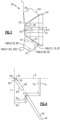
- Figure 3 is a cross-sectional view through the impeller 26. As can be seen, there is a bore 52 to receive the shaft. There is a centerline CL. An outer surface 33 of the hub 28 is defined. A cross-section 70 of the blades 30 may be defined as next to the hub. Another cross-section 72 may be defined as next to the tip, and there is a tip cross-section 74. A diameter d is shown to the outer surface 33 of the hub. As can be appreciated from this view, the diameter d would vary along the surface 33. A dimension Z is defined radially outwardly from the centerline CL and a dimension X is defined along the centerline CL.
- Figure 4 shows a cross-section of each blade 30 as would be found at surface 33, and cross-sections 70 and 72, and 74.
- a dimension Y is defined laterally and perpendicular to the Z axis, and spaced by 90 degress from the Z axis.
- Dimensions X and Y are taken from an origin point 59.
- Dimensions Yp and Ys are shown measured from the axis X in the Y direction and two points on the suction side 62 and pressure side 60.
- dimensions Xs and Xp are measured in the X direction from the Y axis and respectively to a point on the suction side 62 and to a point on the suction side 60.
- the dimensions Zp and Zs are taken in the Z direction to the point in question at each of the pressure 60 and suction 62 sides. These distances will vary along a length of the fan cross-sections at each cross-section 33, 70, 72 and 74.
- Point 32 is at a leading edge.
- Point 29 is the closest point to the Y axis, and spaced from the leading edge.
- Point 35 is the closest point to the X axis, and spaced from the leading edge.
- Point 34 is at the trailing edge.
- Impeller 26 may be machined from a metal, and thus is more lightweight.
- the impeller 26 may be formed of Aluminum 60/61 TM alloy.
- Aluminum 60/61 TM alloy is an aluminum alloy containing at least magnesium and silicone.
- an initial impeller may be made to each of the nine tables above, thus including the dimensions for the cross-sections at 33, 70, 72 and 74.
- the fan blades may be cut away such that they do not extend as far radially outwardly for certain applications. It is presently envisioned that as many as three distinct impellers may be produced from the one initial impeller block.
- cross-section 70 is between 20 and 30% of the entire maximum distance between the surface 33 and the tip 74. In one application it is at 25%.
- the cross-section 72 may be between 70 and 80% of the maximum radius. In one embodiment, it is measured at 75%.
- the uniquely contoured blades provide efficient operation in a long lived and light weight impeller.
Landscapes
- Engineering & Computer Science (AREA)
- Mechanical Engineering (AREA)
- General Engineering & Computer Science (AREA)
- Physics & Mathematics (AREA)
- Geometry (AREA)
- Health & Medical Sciences (AREA)
- General Health & Medical Sciences (AREA)
- Pulmonology (AREA)
- Aviation & Aerospace Engineering (AREA)
- Structures Of Non-Positive Displacement Pumps (AREA)
Abstract
Description
- This application relates to an impeller for a fan wherein the fan blades are relatively thin compared to existing impellers.
- Fan are utilized in any number of applications, and typically have a motor driving an impeller. The impeller has a plurality of blades which are driven to rotate and move a gas from an inlet to an outlet.
- One application for such a system is in a cabin air recirculation system for use on an aircraft. In this application, the fan receives air from an aircraft cabin, and recirculates it back into the cabin.
- Existing fan impellers in many such systems have been formed as a cast item which is relatively heavy.
- An impeller for use in a fan system includes a hub extending along an axis of rotation and having a hub outer surface. A dimension X is measured along the axis of rotation, a radial dimension Z is defined in the radial dimension, and a Y axis is defined laterally and perpendicular to the Z axis, and spaced by 90 degrees from the Z axis. There are also nine blades extending radially outwardly of the hub outer surface, and having a first cross-sectional contour and height at the hub outer surface as shown below, having a dimension Xs measured in the X direction and perpendicular to a Y axis and to a suction side and a dimension Xp measured in the Y direction perpendicular to the X axis and to a pressure side and a dimension Ys measured in the Y direction and perpendicular to the X axis to the suction side and a dimension Zp in the Z dimension in a radial dimension from the centerline to the pressure side and a dimension Zs measured in the same direction and to the suction side, and having the following dimensions with there being an origin for each of the nine blades. All the origins are at a common location along the X axis, and at nine equally circumferentially spaced locations, with a point A defined at a leading edge, a point B being the closest point to the Y axis, and spaced from the leading edge, a point C being the closest point to the X axis, and spaced from the leading edge, and point D being at a trailing edge:
Point No. XP YP ZP A 0.3365 -0.0643 0.9889 B 0.3568 -0.5000 0.9945 C 0.3732 -0.0489 1.0013 D 2.5986 -2.2174 1.2400 Point No. XS YS ZS A 0.3365 -0.0643 0.9889 B 0.3274 -0.0878 0.9903 C 0.3298 -0.1047 0.9951 D 2.5986 -2.2174 1.2400 Point No. XP YP ZP A 0.2792 -0.0541 1.3143 B 0.2960 -0.0415 1.3262 C 0.3098 -0.0399 1.3358 D 2.3186 -2.1718 1.6250 Point No. XS YS ZS A 0.2792 -0.0541 1.3143 B 0.2713 -0.0756 1.3078 C 0.2733 -0.0921 1.3081 D 2.3186 -2.1718 1.6250 - A fan system and a method of replacing a fan impeller are also disclosed. The system and method may utilize an impeller as described above.
- These and other features of the present invention can be best understood from the following specification and drawings, the following of which is a brief description.
-
-
Figure 1 shows a fan and motor system. -
Figure 2A is a front view of a fan impeller according to this disclosure. -
Figure 2B is a side view of theFigure 2A impeller. -
Figure 3 is a cross-sectional view through a disclosed impeller. -
Figure 4 is a cross-section view through a blade on the impeller. -
Figure 1 shows afan system 20. Asource 10 delivers gas to aninlet 11 in afan housing 22. The gas may be air. The air approaches animpeller 26 having a hub outer diameter at 28 and a plurality offan blades 30 having a leadingedge 32 and atrailing edge 34. Adiffuser housing 38 is aft of theimpeller 26. An electric motor 47 has arotor 48 and astator 50. Therotor 48 is driven to rotate, as known, and drives ashaft 42.Shaft 42 is secured to impeller 26 with a connection shown at 44, and including anut 46. Abearing 40 supports theshaft 42.Impeller 26 moves air tooutlet 36. In oneapplication source 10 is an aircraft cabin that recirculates air back into ause 12 that may be the cabin. In such an application, the air is treated, such as by filtering, and then delivered into a mixing chamber where it is mixed with air from an air cycle machine. The mixed air is returned to the aircraft cabin. -
Figure 2A shows theimpeller 26 with theshaft 42 andbolt connection 46. There are nineblades 30 in one embodiment. Each of the blades has a leadingedge 32 and atrailing edge 34. -
Figure 2B is a side view showing thehub structure 28 mounting theblades 30. -
Figure 3 is a cross-sectional view through theimpeller 26. As can be seen, there is abore 52 to receive the shaft. There is a centerline CL. An outer surface 33 of thehub 28 is defined. Across-section 70 of theblades 30 may be defined as next to the hub. Anothercross-section 72 may be defined as next to the tip, and there is atip cross-section 74. A diameter d is shown to the outer surface 33 of the hub. As can be appreciated from this view, the diameter d would vary along the surface 33. A dimension Z is defined radially outwardly from the centerline CL and a dimension X is defined along the centerline CL. -
Figure 4 shows a cross-section of eachblade 30 as would be found at surface 33, andcross-sections - A dimension Y is defined laterally and perpendicular to the Z axis, and spaced by 90 degress from the Z axis. Dimensions X and Y are taken from an
origin point 59. There is asuction side 62 and apressure side 60 ofblade 30. Dimensions Yp and Ys are shown measured from the axis X in the Y direction and two points on thesuction side 62 andpressure side 60. Similarly, dimensions Xs and Xp are measured in the X direction from the Y axis and respectively to a point on thesuction side 62 and to a point on thesuction side 60. The dimensions Zp and Zs are taken in the Z direction to the point in question at each of thepressure 60 andsuction 62 sides. These distances will vary along a length of the fan cross-sections at eachcross-section -
Point 32 is at a leading edge.Point 29 is the closest point to the Y axis, and spaced from the leading edge.Point 35 is the closest point to the X axis, and spaced from the leading edge.Point 34 is at the trailing edge. - Note, for each of the nine
blades 30 there is anorigin 59. The origins are all at a common distance all the X dimensions. The Z and Y origin locations are at nine equally circumferentially spaced locations.TABLE I AT 33 Point No. XP YP ZP 32 0.3365 -0.0643 0.9889 29 0.3568 -0.5000 0.9945 35 0.3732 -0.0489 1.0013 34 2.5986 -2.2174 1.2400 - The following dimensions in ach of the supplemental tables will also be found spaced between
points point 34.TABLE I SUPPLEMENTAL AT 33 XP YP ZP 0.4104 -0.0744 1.0230 0.5038 -0.1533 1.0774 0.6892 -0.3110 1.1723 1.1829 -0.7495 1.3528 1.6731 -1.2210 1.4292 2.1523 -1.7087 1.3958 2.4413 -2.0064 1.3243 2.5550 -2.1228 1.2858 2.6094 -2.1837 1.2620 TABLE II AT 33 Point No. XS YS ZS 32 0.3365 -0.0643 0.9889 29 0.3274 -0.0878 0.9903 35 0.3298 -0.1047 0.9951 34 2.5986 -2.2174 1.2400 TABLE II SUPPLEMENTAL AT 33 XS YS ZS 0.3613 -0.1371 1.0156 0.4544 -0.2156 1.0687 0.6392 -0.3724 1.1612 1.1312 -0.8080 1.3350 1.6198 -1.2753 1.4044 2.0972 -1.7575 1.3644 2.3850 -2.0514 1.2895 2.4982 -2.1662 1.2498 2.5587 -2.2215 1.2297 TABLE III AT 70 Point No. XP YP ZP 32 0.2792 -0.0541 1.3143 29 0.2960 -0.0415 1.3262 35 0.3098 -0.0399 1.3358 34 2.3186 -2.1718 1.6250 TABLE III SUPPLEMENTAL AT 70XP YP ZP 0.3437 -0.0635 1.3581 0.4284 -0.1411 1.4106 0.5959 -0.2965 1.5035 1.0403 -0.7288 1.6860 1.4810 -1.1931 1.7748 1.9118 -1.6747 1.7655 2.1717 -1.9709 1.7136 2.2740 -2.0874 1.6838 2.3187 -2.1471 1.6576 TABLE IV AT 70 Point No. XS YS ZS 32 0.2792 -0.0541 1.3143 29 0.2713 -0.0756 1.3078 35 0.2733 -0.0921 1.3081 34 2.3186 -2.1718 1.6250 TABLE IV SUPPLEMENTAL AT 70 XS YS ZS 0.3024 -0.1245 1.3255 0.3878 -0.2018 1.3751 0.5565 -0.3563 1.4627 1.0036 -0.7843 1.6331 1.4465 -1.2422 1.7117 1.8793 -1.7160 1.6936 2.1403 -2.0069 1.6374 2.2430 -2.1212 1.6061 2.2974 -2.1772 1.5933 TABLE V AT 72 Point No. XP YP ZP 32 0.0648 -0.0158 2.5318 29 0.0805 -0.0081 2.5416 35 0.0924 -0.0097 2.5490 34 1.4994 -2.0383 2.7512 TABLE V SUPPLEMENTAL AT 72XP YP ZP 0.1178 -0.0348 2.5646 0.1785 -0.1131 2.6001 0.2969 -0.2689 2.6627 0.6062 -0.6930 2.7836 0.9122 -1.1324 2.8415 1.2149 -1.5780 2.8378 1.3997 -1.8511 2.8064 1.4726 -1.9589 2.7879 1.5062 -2.0145 2.7738 TABLE VI AT 72 Point No. XS YS ZS 32 0.0648 -0.0158 2.5318 29 0.0555 -0.0323 2.5259 35 0.0558 -0.0462 2.5258 34 1.4994 -2.0383 2.7512 TABLE VI SUPPLEMENTAL AT 72XS YS ZS 0.0754 -0.0777 2.5372 0.1363 -0.1554 2.5716 0.2551 -0.3101 2.6320 0.5655 -0.7306 2.7478 0.8725 -1.1658 2.8012 1.1759 -1.6068 2.7936 1.3609 -1.8769 2.7601 1.4344 -1.9834 2.7413 1.4737 -2.0359 2.7330 TABLE VII AT 74 Point No. XP YP ZP 32 0.0120 -0.0064 2.8313 29 0.0295 0.0000 2.8356 35 0.0418 -0.0026 2.8401 34 1.2984 -2.0055 3.0276 TABLE VII SUPPLEMENTAL AT 74XP YP ZP 0.0648 -0.0295 2.8530 0.1193 -0.1076 2.8851 0.2253 -0.2629 2.9414 0.5005 -0.6840 3.0495 0.7733 -1.1173 3.1008 1.0455 -1.5540 3.0979 1.2126 -1.8212 3.0707 1.2790 -1.9267 3.0547 1.3102 -1.9814 3.0437 TABLE VIII AT 74 Point No. XS YS ZS 32 0.0120 -0.0064 2.8313 29 0.0012 -0.0220 2.8311 35 0.0000 -0.0350 2.8334 34 1.2984 -2.0055 3.0276 TABLE VIII SUPPLEMENTAL AT 74XS YS ZS 0.0177 -0.0658 2.8452 0.0722 -0.1437 2.8763 0.1783 -0.2984 2.9304 0.4538 -0.7176 3.0323 0.7271 -1.1480 3.0780 0.9995 -1.5813 3.0707 1.1667 -1.8463 3.0412 1.2331 -1.9508 3.0245 1.2694 -2.0024 3.0166 TABLE IX AT 33 Point No. X Z 1 0.3343 0.5800 3 0.2952 0.6167 6 0.2269 0.7005 9 0.2110 0.8497 12 0.5521 1.1387 15 1.3384 1.6773 18 2.1246 2.2159 21 2.7422 2.6317 24 2.9848 2.7235 27 3.1657 2.7481 30 3.2940 2.7500 - In the past, fan impellers for use in cabin air recirculation systems have been generally cast and thus heavy.
Impeller 26 may be machined from a metal, and thus is more lightweight. In one application, theimpeller 26 may be formed ofAluminum 60/61™ alloy.Aluminum 60/61™ alloy is an aluminum alloy containing at least magnesium and silicone. - In a unique benefit from this disclosure, an initial impeller may be made to each of the nine tables above, thus including the dimensions for the cross-sections at 33, 70, 72 and 74. However, subsequently, the fan blades may be cut away such that they do not extend as far radially outwardly for certain applications. It is presently envisioned that as many as three distinct impellers may be produced from the one initial impeller block. In the initial block, it could be said that
cross-section 70 is between 20 and 30% of the entire maximum distance between the surface 33 and thetip 74. In one application it is at 25%. Similarly, thecross-section 72 may be between 70 and 80% of the maximum radius. In one embodiment, it is measured at 75%. - Note that the origin for all of the above tables have an X location selected at the
leading edge 32 of the cross-section in Table VIII. - The uniquely contoured blades provide efficient operation in a long lived and light weight impeller.
- Although an impeller has been disclosed, a worker of skill in this art would recognize that certain modifications would come within the scope of this disclosure. For that reason, the following claims should be cited to determine the true scope and content.
Claims (15)
- An impeller (26) for use in a fan system (20) comprising:a hub (28) extending along an axis of rotation and having a hub outer surface (33);a dimension X measured along the axis of rotation, a radial dimension Z defined in the radial dimension, and a Y axis defined laterally and perpendicular to the Z axis, and spaced by 90 degrees from the Z axis,there also being nine blades (30) extending radially outwardly of the hub outer surface, and having a first cross-sectional contour and height at the hub outer surface as shown below, having a dimension Xs measured in the X direction and perpendicular to a Y axis and to a suction side and a dimension Xp measured in the Y direction perpendicular to the X axis and to a pressure side and a dimension Ys measured in the Y direction and perpendicular to the X axis to the suction side and a dimension Zp in the Z dimension in a radial dimension from the centerline to the pressure side and a dimension Zs measured in the same direction and to the suction side, and having the following dimensions with there being an origin for each of the nine blades, and all said origins being at a common location along the X axis, and at nine equally circumferentially spaced locations, with a point A defined at a leading edge (32), a point B being the closest point to the Y axis, and spaced from the leading edge, a point C being the closest point to the X axis, and spaced from the leading edge, and point D being at a trailing edge (34):
Point No. XP YP ZP A 0.3365 -0.0643 0.9889 B 0.3568 -0.5000 0.9945 C 0.3732 -0.0489 1.0013 D 2.5986 -2.2174 1.2400 Point No. XS YS ZS A 0.3365 -0.0643 0.9889 B 0.3274 -0.0878 0.9903 C 0.3298 -0.1047 0.9951 D 2.5986 -2.2174 1.2400 further, there being a second cross-sectional contour spaced from the hub outer surface in a radially outer direction having the following dimensions:Point No. XP YP ZP A 0.2792 -0.0541 1.3143 B 0.2960 -0.0415 1.3262 C 0.3098 -0.0399 1.3358 D 2.3186 -2.1718 1.6250 Point No. XS YS ZS A 0.2792 -0.0541 1.3143 B 0.2713 -0.0756 1.3078 C 0.2733 -0.0921 1.3081 D 2.3186 -2.1718 1.6250 all of the dimensions measured above having a tolerance in the range of +/.020 inch (+/- .0508 cm). - The impeller (26) as set forth in claim 1, wherein the hub (28) having an outer diameter along its outer surface with a first point taken at an axially forwardmost point, and measured in eleven spaced data points and having X and Z dimensions as follows:
Point No. X Z 1 0.3343 0.5800 2 0.2952 0.6167 3 0.2269 0.7005 4 0.2110 0.8497 5 0.5521 1.1387 6 1.3384 1.6773 7 2.1246 2.2159 8 2.7422 2.6317 9 2.9848 2.7235 10 3.1657 2.7481 11 3.2940 2.7500 - The impeller (26) as set forth in claim 1 or 2, wherein said impeller is formed of an aluminum alloy containing at least magnesium and silicone.
- The impeller (26) as set forth in any preceding claim, wherein a third cross-sectional contour of the fan blades (30) taken radially outward of the second cross-sectional contour has the following dimensions:
Point No. XP YP ZP A 0.0648 -0.0158 2.5318 B 0.0805 -0.0081 2.5416 C 0.0924 -0.0097 2.5490 D 1.4994 -2.0383 2.7512 Point No. XS YS ZS A 0.0648 -0.0158 2.5318 B 0.0555 -0.0323 2.5259 C 0.0558 -0.0462 2.5258 D 1.4994 -2.0383 2.7512 again with the tolerances set forth in claim 1, and optionallywherein a tip dimension of an initially formed impeller has the following cross-sectional dimensions:Point No. XP YP ZP A 0.0120 -0.0064 2.8313 B 0.0295 0.0000 2.8356 C 0.0418 -0.0026 2.8401 D 1.2984 -2.0055 3.0276 Point No. XS YS ZS A 0.0120 -0.0064 2.8313 B 0.0012 -0.0220 2.8311 C 0.0000 -0.0350 2.8334 D 1.2984 -2.0055 3.0276 again with the tolerances of claim 1, and further optionallywherein said second cross-section is taken at 20-30% of the maximum distance between the hub outer surface and a tip of an initially formed impeller. - The impeller as set forth in any preceding claim, wherein the impeller (26) wherein the first cross-sectional contour having additional dimensions at points between the points 2 or 3 and point 4:
XP YP ZP 0.4104 -0.0744 1.0230 0.5038 -0.1533 1.0774 0.6892 -0.3110 1.1723 1.1829 -0.7495 1.3528 1.6731 -1.2210 1.4292 2.1523 -1.7087 1.3958 2.4413 -2.0064 1.3243 2.5550 -2.1228 1.2858 2.6094 -2.1837 1.2620 XS YS ZS 0.3613 -0.1371 1.0156 0.4544 -0.2156 1.0687 0.6392 -0.3724 1.1612 1.1312 -0.8080 1.3350 1.6198 -1.2753 1.4044 2.0972 -1.7575 1.3644 2.3850 -2.0514 1.2895 2.4982 -2.1662 1.2498 2.5587 -2.2215 1.2297 and the second cross-sectional contour having additional dimensions at points between the points 2 or 3 and point 4:XP YP ZP 0.3437 -0.0635 1.3581 0.4284 -0.1411 1.4106 0.5959 -0.2965 1.5035 1.0403 -0.7288 1.6860 1.4810 -1.1931 1.7748 1.9118 -1.6747 1.7655 2.1717 -1.9709 1.7136 2.2740 -2.0874 1.6838 2.3187 -2.1471 1.6576 XS YS ZS 0.3024 -0.1245 1.3255 0.3878 -0.2018 1.3751 0.5565 -0.3563 1.4627 1.0036 -0.7843 1.6331 1.4465 -1.2422 1.7117 1.8793 -1.7160 1.6936 2.1403 -2.0069 1.6374 2.2430 -2.1212 1.6061 2.2974 -2.1772 1.5933 again with the tolerances set forth in claim 1. - A fan system (20) comprising:an electric motor (47) having a shaft, said shaft being fixed to rotate an impeller (26), and said electric motor and said impeller received within a housing having a fan inlet and a fan outlet; andsaid impeller having a hub (28) extending along an axis of rotation and having a hub outer surface (33);a dimension X measured along the axis of rotation, a radial dimension Z defined in the radial dimension, and a Y axis defined laterally and perpendicular to the Z axis, and spaced by 90 degrees from the Z axis,there also being nine blades (30) extending radially outwardly of the hub outer surface, and having a first cross-sectional contour and height at the hub outer surface as shown below, having a dimension Xs measured in the X direction and perpendicular to a Y axis and to a suction side and a dimension Xp measured in the Y direction perpendicular to the X axis and to a pressure side and a dimension Ys measured in the Y direction and perpendicular to the X axis to the suction side and a dimension Zp in the Z dimension in a radial dimension from the centerline to the pressure side and a dimension Zs measured in the same direction and to the suction side, and having the following dimensions with there being an origin for each of the nine blades, and all said origins being at a common location along the X axis, and at nine equally circumferentially spaced locations, with a point A defined at a leading edge (32), a point B being the closest point to the Y axis, and spaced from the leading edge, a point C being the closest point to the X axis, and spaced from the leading edge, and point D being at a trailing edge (34):
Point No. XP YP ZP A 0.3365 -0.0643 0.9889 B 0.3568 -0.5000 0.9945 C 0.3732 -0.0489 1.0013 D 2.5986 -2.2174 1.2400 Point No. XP YP ZP A 0.2792 -0.0541 1.3143 B 0.2960 -0.0415 1.3262 C 0.3098 -0.0399 1.3358 D 2.3186 -2.1718 1.6250 further, there being a second cross-sectional contour spaced from the hub outer surface in a radially outer direction having the following dimensions:Point No. XS YS ZS A 0.3365 -0.0643 0.9889 B 0.3274 -0.0878 0.9903 C 0.3298 -0.1047 0.9951 D 2.5986 -2.2174 1.2400 Point No. XS YS ZS A 0.2792 -0.0541 1.3143 B 0.2713 -0.0756 1.3078 C 0.2733 -0.0921 1.3081 D 2.3186 -2.1718 1.6250 all of the dimensions measured above having a tolerance in the range of +/.020 inch (+/- .0508 cm). - The fan system as set forth in claim 6, wherein the hub (28) having an outer diameter along its outer surface with a first point taken at an axially forwardmost point, and measured in eleven equally data points and having X and Z dimensions as follows:
Point No. X Z 1 0.3343 0.5800 2 0.2952 0.6167 3 0.2269 0.7005 4 0.2110 0.8497 5 0.5521 1.1387 6 1.3384 1.6773 7 2.1246 2.2159 8 2.7422 2.6317 9 2.9848 2.7235 10 3.1657 2.7481 11 3.2940 2.7500 - The fan system as set forth in claim 6 or 7, wherein said impeller (26) is formed of an aluminum alloy containing at least magnesium and silicone.
- The fan system as set forth in any of claims 6 to 8, wherein a third cross-section of the fan blade (30) taken radially outward of the second cross-section has the following dimensions:
Point No. XP YP ZP A 0.0648 -0.0158 2.5318 B 0.0805 -0.0081 2.5416 C 0.0924 -0.0097 2.5490 D 1.4994 -2.0383 2.7512 Point No. XS YS ZS A 0.0648 -0.0158 2.5318 B 0.0555 -0.0323 2.5259 C 0.0558 -0.0462 2.5258 D 1.4994 -2.0383 2.7512 - The fan system as set forth in any of claims 6 to 9, wherein a tip dimension of an initially formed impeller (26) has the following dimensions:
Point No. XP YP ZP A 0.0120 -0.0064 2.8313 B 0.0295 0.0000 2.8356 C 0.0418 -0.0026 2.8401 D 1.2984 -2.0055 3.0276 Point No. XS YS ZS A 0.0120 -0.0064 2.8313 B 0.0012 -0.0220 2.8311 C 0.0000 -0.0350 2.8334 D 1.2984 -2.0055 3.0276 - The fan system as set forth in any of claims 6 to 10, wherein said second cross-section is taken at 20-30% of the maximum distance between the hub outer surface (33) and a tip of an initially formed impeller (26), and/or
wherein said input is to be connected to receive air from an aircraft cabin and said outlet is to be connected to deliver air back into the aircraft cabin. - A method of replacing an impeller in a fan air recirculation system comprising the steps of:removing an existing fan impeller from a fan system having an electric motor driving a shaft to drive the existing impeller, the existing impeller and the electric motor and shaft received within a housing having an inlet and an outlet; andreplacing the existing impeller with a replacement impeller,the replacement impeller having a hub extending along an axis of rotation and having a hub outer surface;a dimension X measured along the axis of rotation, a radial dimension Z defined in the radial dimension, and a Y axis defined laterally and perpendicular to the Z axis, and spaced by 90 degrees from the Z axis,there also being nine blades extending radially outwardly of the hub outer surface, and having a first cross-sectional contour and height at the hub outer surface as shown below, having a dimension Xs measured in the X direction and perpendicular to a Y axis and to a suction side and a dimension Xp measured in the Y direction perpendicular to the X axis and to a pressure side and a dimension Ys measured in the Y direction and perpendicular to the X axis to the suction side and a dimension Zp in the Z dimension in a radial dimension from the centerline to the pressure side and a dimension Zs measured in the same direction and to the suction side, and having the following dimensions with there being an origin for each of the nine blades, and all said origins being at a common location along the X axis, and at nine equally circumferentially spaced locations, with a point A defined at a leading edge, a point B being the closest point to the Y axis, and spaced from the leading edge, a point C being the closest point to the X axis, and spaced from the leading edge, and point D being at a trailing edge:
Point No. XP YP ZP A 0.3365 -0.0643 0.9889 B 0.3568 -0.5000 0.9945 C 0.3732 -0.0489 1.0013 D 2.5986 -2.2174 1.2400 Point No. XS YS ZS A 0.3365 -0.0643 0.9889 B 0.3274 -0.0878 0.9903 C 0.3298 -0.1047 0.9951 D 2.5986 -2.2174 1.2400 further, there being a second cross-sectional contour spaced from the hub outer surface in a radially outer direction having the following dimensions:Point No. XP YP ZP A 0.2792 -0.0541 1.3143 B 0.2960 -0.0415 1.3262 C 0.3098 -0.0399 1.3358 D 2.3186 -2.1718 1.6250 Point No. XS YS ZS A 0.2792 -0.0541 1.3143 B 0.2713 -0.0756 1.3078 C 0.2733 -0.0921 1.3081 D 2.3186 -2.1718 1.6250 all of the dimensions measured above having a tolerance in the range of +/.020 inch (+/-.0508 cm). - The method as set forth in claim 12, wherein the hub having an outer diameter along its outer surface with a first point taken at an axially forwardmost point, and measured in eleven equally spaced data points and having X and Z dimensions as
Point No. X Z 1 0.3343 0.5800 2 0.2952 0.6167 3 0.2269 0.7005 4 0.2110 0.8497 5 0.5521 1.1387 6 1.3384 1.6773 7 2.1246 2.2159 8 2.7422 2.6317 9 2.9848 2.7235 10 3.1657 2.7481 11 3.2940 2.7500
again with the tolerances of claim 12
optionally wherein said replacement impeller is formed of an aluminum alloy containing at least magnesium and silicone. - The method as set forth in claim 12 or 13, wherein a third cross-section of the fan blades taken radially outward of the second cross-section has the following dimensions:
Point No. XP YP ZP A 0.0648 -0.0158 2.5318 B 0.0805 -0.0081 2.5416 C 0.0924 -0.0097 2.5490 D 1.4994 -2.0383 2.7512 Point No. XP YP ZP A 0.0648 -0.0158 2.5318 B 0.0805 -0.0081 2.5416 C 0.0924 -0.0097 2.5490 D 1.4994 -2.0383 2.7512 - The method as set forth in any of claims 12 to 14, wherein a tip dimension of an initially formed replacement impeller has the following cross-sectional contour dimensions:
Point No. XP YP ZP A 0.0120 -0.0064 2.8313 B 0.0295 0.0000 2.8356 C 0.0418 -0.0026 2.8401 D 1.2984 -2.0055 3.0276 Point No. XS YS ZS A 0.0120 -0.0064 2.8313 B 0.0012 -0.0220 2.8311 C 0.0000 -0.0350 2.8334 D 1.2984 -2.0055 3.0276 again with the tolerances of claim 1, optionallywherein said second cross-sectional contour is taken at 20-30% of a maximum distance between the hub outer surface and a tip of the initially formed replacement impeller.
Applications Claiming Priority (1)
| Application Number | Priority Date | Filing Date | Title |
|---|---|---|---|
| US17/541,369 US11754088B2 (en) | 2021-12-03 | 2021-12-03 | Fan impeller with thin blades |
Publications (1)
| Publication Number | Publication Date |
|---|---|
| EP4191071A1 true EP4191071A1 (en) | 2023-06-07 |
Family
ID=84387931
Family Applications (1)
| Application Number | Title | Priority Date | Filing Date |
|---|---|---|---|
| EP22211081.9A Pending EP4191071A1 (en) | 2021-12-03 | 2022-12-02 | Fan impeller with thin blades |
Country Status (2)
| Country | Link |
|---|---|
| US (1) | US11754088B2 (en) |
| EP (1) | EP4191071A1 (en) |
Citations (3)
| Publication number | Priority date | Publication date | Assignee | Title |
|---|---|---|---|---|
| EP1312807A2 (en) * | 2001-11-15 | 2003-05-21 | Nuovo Pignone Holding S.P.A. | Rotor blade for centrifugal compressor |
| WO2012072996A1 (en) * | 2010-12-02 | 2012-06-07 | Dyson Technology Limited | A fan |
| CN113374731A (en) * | 2021-06-24 | 2021-09-10 | 珠海格力电器股份有限公司 | Turbine rotor, expander and air cycle machine |
Family Cites Families (14)
| Publication number | Priority date | Publication date | Assignee | Title |
|---|---|---|---|---|
| US3363832A (en) * | 1967-03-02 | 1968-01-16 | Carrier Corp | Fans |
| US4312191A (en) | 1980-02-15 | 1982-01-26 | Sundstrand Corporation | Environmental control system for aircraft with improved efficiency |
| DE102004017727A1 (en) * | 2003-04-19 | 2004-11-04 | Ebm-Papst St. Georgen Gmbh & Co. Kg | Fan for equipment comprises an air-conveying channel containing a fan wheel rotating about a central axis and having a central hub with an outer periphery on which fan blades are fixed |
| ITBO20040468A1 (en) * | 2004-07-23 | 2004-10-23 | Spal Srl | AXIAL FAN WITH INCREASED FLOW |
| US7757502B2 (en) | 2004-09-22 | 2010-07-20 | Hamilton Sundstrand Corporation | RAM fan system for an aircraft environmental control system |
| CN102094836B (en) * | 2009-12-14 | 2014-11-05 | 国立大学法人东京大学 | Double counter-rotating axial flow fan |
| US9103568B2 (en) | 2013-08-02 | 2015-08-11 | Hamilton Sundstrand Corporation | Compressor housing for an air cycle machine |
| DE102014102311A1 (en) * | 2014-02-21 | 2015-08-27 | Ebm-Papst St. Georgen Gmbh & Co. Kg | Fan with a paddle wheel |
| DE102015224096A1 (en) * | 2015-12-02 | 2017-06-08 | Mahle International Gmbh | Fan wheel for an axial fan |
| JP6463548B2 (en) * | 2016-03-07 | 2019-02-06 | 三菱電機株式会社 | Axial blower and outdoor unit |
| KR102061517B1 (en) * | 2016-09-01 | 2020-02-11 | 삼성전자주식회사 | Cleaner |
| US10533440B2 (en) * | 2017-05-15 | 2020-01-14 | General Electric Company | Turbine nozzle airfoil profile |
| DE102017114679A1 (en) * | 2017-06-30 | 2019-01-03 | Ebm-Papst Mulfingen Gmbh & Co. Kg | blower |
| DE102017008292A1 (en) * | 2017-09-05 | 2019-03-07 | Brose Fahrzeugteile GmbH & Co. Kommanditgesellschaft, Würzburg | fan |
-
2021
- 2021-12-03 US US17/541,369 patent/US11754088B2/en active Active
-
2022
- 2022-12-02 EP EP22211081.9A patent/EP4191071A1/en active Pending
Patent Citations (3)
| Publication number | Priority date | Publication date | Assignee | Title |
|---|---|---|---|---|
| EP1312807A2 (en) * | 2001-11-15 | 2003-05-21 | Nuovo Pignone Holding S.P.A. | Rotor blade for centrifugal compressor |
| WO2012072996A1 (en) * | 2010-12-02 | 2012-06-07 | Dyson Technology Limited | A fan |
| CN113374731A (en) * | 2021-06-24 | 2021-09-10 | 珠海格力电器股份有限公司 | Turbine rotor, expander and air cycle machine |
Also Published As
| Publication number | Publication date |
|---|---|
| US20230175521A1 (en) | 2023-06-08 |
| US11754088B2 (en) | 2023-09-12 |
Similar Documents
| Publication | Publication Date | Title |
|---|---|---|
| KR101819240B1 (en) | Airfoil shape for compressor | |
| EP1778982B1 (en) | Compressor wheel housing | |
| US8814510B2 (en) | Turbine nozzle for air cycle machine | |
| EP1921261A2 (en) | Airfoil shape for a compressor | |
| CN1041992A (en) | multistage centrifugal compressor | |
| EP1921264A2 (en) | Airfoil shape for a compressor | |
| EP1916387A2 (en) | Airfoil shape for a compressor | |
| US8556516B2 (en) | Compressor bearing cooling inlet plate | |
| CN106968985B (en) | Outlet housing for a cabin air compressor | |
| US11193494B2 (en) | Compressor wheel for turbocharger | |
| EP3388685A1 (en) | Volute for aircraft engine mounted fuel boost pump, boost pump and associated method | |
| EP3722616A1 (en) | Deswirler assembly for a centrifugal compressor | |
| US11754088B2 (en) | Fan impeller with thin blades | |
| US20040013520A1 (en) | Fluid flow machine (turbomachine) with increased rotor-stator ratio | |
| CN215762422U (en) | Impeller with vortex-eliminating, restraining and separating functions, compressor, air conditioner and automobile | |
| CN106151067B (en) | The rotor of vacuum pump | |
| JP2928615B2 (en) | Turbo vacuum pump | |
| US20240384726A1 (en) | Method of manufacturing rotor blade of vacuum pump, rotor blade of vacuum pump, and vacuum pump | |
| US12270409B2 (en) | Radial compressor and method for operating a radial compressor | |
| CN117905712A (en) | Two-stage variable-speed low-noise axial flow fan | |
| US20090110547A1 (en) | Method for producing a contoured gap, and turbo-engine comprising contoured gap | |
| GB2599565A (en) | Fan for an electrical generator | |
| EP4430308A1 (en) | Turbomolecular pump bladed disc | |
| WO2024126246A1 (en) | Vacuum pump and cooling fan for vacuum pump | |
| US20250163810A1 (en) | Notched turbine airfoils for weight reduction in gas turbine engines |
Legal Events
| Date | Code | Title | Description |
|---|---|---|---|
| PUAI | Public reference made under article 153(3) epc to a published international application that has entered the european phase |
Free format text: ORIGINAL CODE: 0009012 |
|
| STAA | Information on the status of an ep patent application or granted ep patent |
Free format text: STATUS: THE APPLICATION HAS BEEN PUBLISHED |
|
| AK | Designated contracting states |
Kind code of ref document: A1 Designated state(s): AL AT BE BG CH CY CZ DE DK EE ES FI FR GB GR HR HU IE IS IT LI LT LU LV MC ME MK MT NL NO PL PT RO RS SE SI SK SM TR |
|
| STAA | Information on the status of an ep patent application or granted ep patent |
Free format text: STATUS: REQUEST FOR EXAMINATION WAS MADE |
|
| 17P | Request for examination filed |
Effective date: 20231205 |
|
| RBV | Designated contracting states (corrected) |
Designated state(s): AL AT BE BG CH CY CZ DE DK EE ES FI FR GB GR HR HU IE IS IT LI LT LU LV MC ME MK MT NL NO PL PT RO RS SE SI SK SM TR |
|
| STAA | Information on the status of an ep patent application or granted ep patent |
Free format text: STATUS: EXAMINATION IS IN PROGRESS |
|
| 17Q | First examination report despatched |
Effective date: 20250709 |