EP4191053A1 - Windenergieanlagen-rotorblatt - Google Patents
Windenergieanlagen-rotorblatt Download PDFInfo
- Publication number
- EP4191053A1 EP4191053A1 EP21212511.6A EP21212511A EP4191053A1 EP 4191053 A1 EP4191053 A1 EP 4191053A1 EP 21212511 A EP21212511 A EP 21212511A EP 4191053 A1 EP4191053 A1 EP 4191053A1
- Authority
- EP
- European Patent Office
- Prior art keywords
- rotor blade
- cross
- wind turbine
- web
- turbine rotor
- Prior art date
- Legal status (The legal status is an assumption and is not a legal conclusion. Google has not performed a legal analysis and makes no representation as to the accuracy of the status listed.)
- Granted
Links
Images


Classifications
-
- F—MECHANICAL ENGINEERING; LIGHTING; HEATING; WEAPONS; BLASTING
- F03—MACHINES OR ENGINES FOR LIQUIDS; WIND, SPRING, OR WEIGHT MOTORS; PRODUCING MECHANICAL POWER OR A REACTIVE PROPULSIVE THRUST, NOT OTHERWISE PROVIDED FOR
- F03D—WIND MOTORS
- F03D1/00—Wind motors with rotation axis substantially parallel to the air flow entering the rotor
- F03D1/06—Rotors
- F03D1/065—Rotors characterised by their construction elements
- F03D1/0675—Rotors characterised by their construction elements of the blades
-
- F—MECHANICAL ENGINEERING; LIGHTING; HEATING; WEAPONS; BLASTING
- F03—MACHINES OR ENGINES FOR LIQUIDS; WIND, SPRING, OR WEIGHT MOTORS; PRODUCING MECHANICAL POWER OR A REACTIVE PROPULSIVE THRUST, NOT OTHERWISE PROVIDED FOR
- F03D—WIND MOTORS
- F03D80/00—Details, components or accessories not provided for in groups F03D1/00 - F03D17/00
- F03D80/40—Ice detection; De-icing means
-
- F—MECHANICAL ENGINEERING; LIGHTING; HEATING; WEAPONS; BLASTING
- F03—MACHINES OR ENGINES FOR LIQUIDS; WIND, SPRING, OR WEIGHT MOTORS; PRODUCING MECHANICAL POWER OR A REACTIVE PROPULSIVE THRUST, NOT OTHERWISE PROVIDED FOR
- F03D—WIND MOTORS
- F03D1/00—Wind motors with rotation axis substantially parallel to the air flow entering the rotor
- F03D1/06—Rotors
- F03D1/065—Rotors characterised by their construction elements
- F03D1/0658—Arrangements for fixing wind-engaging parts to a hub
-
- F—MECHANICAL ENGINEERING; LIGHTING; HEATING; WEAPONS; BLASTING
- F03—MACHINES OR ENGINES FOR LIQUIDS; WIND, SPRING, OR WEIGHT MOTORS; PRODUCING MECHANICAL POWER OR A REACTIVE PROPULSIVE THRUST, NOT OTHERWISE PROVIDED FOR
- F03D—WIND MOTORS
- F03D80/00—Details, components or accessories not provided for in groups F03D1/00 - F03D17/00
- F03D80/40—Ice detection; De-icing means
- F03D80/402—De-icing by convective heating
-
- F—MECHANICAL ENGINEERING; LIGHTING; HEATING; WEAPONS; BLASTING
- F03—MACHINES OR ENGINES FOR LIQUIDS; WIND, SPRING, OR WEIGHT MOTORS; PRODUCING MECHANICAL POWER OR A REACTIVE PROPULSIVE THRUST, NOT OTHERWISE PROVIDED FOR
- F03D—WIND MOTORS
- F03D80/00—Details, components or accessories not provided for in groups F03D1/00 - F03D17/00
- F03D80/60—Cooling or heating of wind motors
-
- F—MECHANICAL ENGINEERING; LIGHTING; HEATING; WEAPONS; BLASTING
- F03—MACHINES OR ENGINES FOR LIQUIDS; WIND, SPRING, OR WEIGHT MOTORS; PRODUCING MECHANICAL POWER OR A REACTIVE PROPULSIVE THRUST, NOT OTHERWISE PROVIDED FOR
- F03D—WIND MOTORS
- F03D1/00—Wind motors with rotation axis substantially parallel to the air flow entering the rotor
- F03D1/06—Rotors
- F03D1/0608—Rotors characterised by their aerodynamic shape
- F03D1/0633—Rotors characterised by their aerodynamic shape of the blades
- F03D1/0641—Rotors characterised by their aerodynamic shape of the blades of the section profile of the blades, i.e. aerofoil profile
-
- Y—GENERAL TAGGING OF NEW TECHNOLOGICAL DEVELOPMENTS; GENERAL TAGGING OF CROSS-SECTIONAL TECHNOLOGIES SPANNING OVER SEVERAL SECTIONS OF THE IPC; TECHNICAL SUBJECTS COVERED BY FORMER USPC CROSS-REFERENCE ART COLLECTIONS [XRACs] AND DIGESTS
- Y02—TECHNOLOGIES OR APPLICATIONS FOR MITIGATION OR ADAPTATION AGAINST CLIMATE CHANGE
- Y02E—REDUCTION OF GREENHOUSE GAS [GHG] EMISSIONS, RELATED TO ENERGY GENERATION, TRANSMISSION OR DISTRIBUTION
- Y02E10/00—Energy generation through renewable energy sources
- Y02E10/70—Wind energy
- Y02E10/72—Wind turbines with rotation axis in wind direction
Definitions
- the present invention relates to a wind turbine rotor blade.
- a rotor blade heater can be used. In this case, either heating can be provided on the outside of the rotor blade or heated air can be provided inside the rotor blade.
- a rotor blade heater is often used to prevent the rotor blades from icing up.
- typically heated air is introduced into the interior of the rotor blade in the region of the rotor blade root.
- the heated air in turn heats the rotor blade shell, for example in the area of the rotor blade leading edge, so that the rotor blade can be de-iced.
- WO 2017/021350 A1 shows a wind turbine rotor blade with a rotor blade root area and a rotor blade tip area. Furthermore, at least one web is provided along a longitudinal direction of the rotor blade. A deflection unit can be provided on the web for deflecting the air.
- WO 2018/211055 shows a rotor blade of a wind turbine with a rotor blade which has a web and a deflection unit at the rotor blade tip for deflecting heated air.
- a wind turbine rotor blade is provided with a rotor blade shell, which surrounds an inner volume, and at least one cross-sectional constriction for narrowing the free cross-section of the inner volume.
- the constriction allows the flow speed to be increased, which leads to improved heat transfer and thus better heating of the rotor blades.
- the rotor blade has at least one web along a longitudinal direction of the rotor blade.
- the at least one cross-sectional constriction is arranged on the at least one web or attached to the web.
- the rotor blade has at least one first and second web along a longitudinal direction of the rotor blade. Furthermore, a first air duct is provided between a leading edge of the rotor blade and a first web, with at least one first cross-sectional constriction being provided in the first air duct.
- the rotor blade has a second air duct between a web and a rotor blade trailing edge.
- a second constriction is provided at least partially in the second air duct along the longitudinal direction of the rotor blade.
- the rotor blade has at least a third cross-sectional restriction in a third air duct between the first and second webs.
- the rotor blade has a rotor blade heating system in or at the root of the rotor blade.
- the rotor blade heating system generates warm air, which is transported into the inner volume of the rotor blade.
- the invention also relates to a wind power plant with at least one wind power plant rotor blade described above.
- a wind turbine rotor blade is provided with a (two-piece) blade shell surrounding an interior volume.
- the rotor blade also has a rotor blade root and a rotor blade tip.
- At least one web can be provided at least in sections along a longitudinal direction of the rotor blade between the two blade shells, so that the inner volume of the rotor blade is divided into at least two sections.
- the rotor blade also has a rotor blade heater, which is provided, for example, in the area of the rotor blade root and conveys heated air into the interior volume of the rotor blade. To improve the effectiveness of the blade heater, at least one narrowing of the cross section is provided in the inner volume, so that the air volume that remains free in the inner volume is reduced.
- the free cross-section for the air flow is thus also reduced.
- the reduction in the free cross-section causes an increase in the flow speed, since the rotor blade heater provides an essentially constant air volume flow.
- With the increased flow speed there is improved heat transfer to the rotor blade shells, so that improved rotor blade heating can be achieved by providing the cross-sectional constrictions.
- a web is provided between the two blade shells (pressure side, suction side), so that an air duct is created in the area of the rotor blade leading edge, through which the air heated by the rotor blade heater can flow.
- At least one first cross-sectional constriction is provided in the area of the first channel, at least partially along a longitudinal axis of the rotor blade.
- a second web is provided between the two rotor blade shells, so that a second channel is created in the region of the rotor blade trailing edge.
- An optional second narrowing of the cross section can be provided in this second channel, so that the cross section of the second channel that is free for the air flow is reduced.
- a third channel may be provided at least partially between the first and second lands.
- third cross-sectional constrictions may be provided to reduce the free cross-sectional area.
- a first cross-sectional constriction in the region of a rotor blade length of 20 to 30 m can be provided in the first duct.
- three first cross-sectional constrictions can be provided in the first channel along a longitudinal axis of the rotor blade, with a first cross-sectional constriction in the case of a rotor blade length of between 10 and 15 m, a second cross-sectional constriction in the range of a rotor blade length of 20 to 25 m and/or a third narrowing of the cross section can be provided in the area of a rotor blade length of 30 to 35 m.
- the flow speed (which results from the volume flow and the cross section) is increased by reducing the free cross-sectional area in a ventilation duct.
- the heat transfer coefficient ⁇ also increases.
- the inner blade flow is changed to improve heat transfer of the heated air from the blade heater to the rotor blade shell.
- the narrowing of the cross-section represents a passive way of increasing the flow velocity.
- the cross-sectional constrictions can be retrofitted.
- the wind turbine 100 has a tower 102 and a nacelle 104 on the tower 102 .
- An aerodynamic rotor 106 with three rotor blades 200 and a spinner 110 is provided on the nacelle 104 .
- the aerodynamic rotor 106 is caused to rotate by the wind and thus also rotates a rotor or rotor of a generator, which is directly or indirectly coupled to the aerodynamic rotor 106 .
- the electrical generator is arranged in the nacelle 104 and generates electrical energy.
- the pitch angles of the rotor blades 200 can be changed by pitch motors on the rotor blade roots of the respective rotor blades 200.
- a rotor blade heater 500 can be provided in the region of a rotor blade root for rotor blade de-icing. As an alternative to this, the rotor blade heater 500 can be provided in the area of a rotor hub or on a rotor blade connection. The rotor blade heater 500 generates warm air and then directs it to the inside of the rotor blade for de-icing of the rotor blade or prevention of icing.
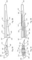
- Figure 2A shows a cross section of a rotor blade
- Figure 2B shows a longitudinal section of a rotor blade.
- the rotor blade 200 has two blade shells 210, 220 which surround an inner volume 203.
- the rotor blade 200 also has a rotor blade leading edge 230 and a rotor blade trailing edge 240 .
- Webs 231, 232 can be provided between the blade shells 210, 220, so that the inner volume 203 is divided into different sections or channels 250, 260 and 270 (first channel 250 between leading edge 230 and first web 231, second channel 260 between trailing edge 240 and second web 232 and third channel 270 between the first and second web 231, 232) can be divided.
- the web 231 can be longer than the web 232, for example.
- Figures 3A and 3B show a corresponding cross section of a rotor blade and a longitudinal section of the rotor blade according to an embodiment of the invention. While in accordance with the rotor blade Figures 2A and 2B channels 250, 260 and 270 are shown unchanged are in channels according to FIG Figures 3A and 3B at least in sections, cross-sectional constrictions 310 in the first channel 250, second cross-sectional constrictions 320 in the second channel 260 and/or optionally third cross-sectional constrictions 330 in the third channel 270 are provided. In Figure 3B shows the distribution of the cross-sectional constrictions 310, 320, 330 along a longitudinal axis of the rotor blade.
- both the cross-sections of the cross-sectional constrictions and their distribution along the longitudinal axis of the rotor blade can differ from those in Figures 3A and 3B shown cross-sections and longitudinal distributions deviate.
- the narrowing of the cross section results in a higher flow speed of the air flowing through the rotor blade heater 500 into the interior (into the channels 250, 260, 270) of the rotor blade.
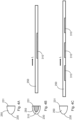
- Figure 4A shows a schematic cross section of a first channel of FIG Figure 3A . No cross-sectional constrictions are provided in the first channel 250 .
- cross-sectional constrictions are provided in the first channel 250 according to an embodiment of the invention.
- the distribution of cross-sectional constrictions is also in Figure 4B shown in a schematic longitudinal section.
- the cross-sectional constrictions 310 can be provided, for example, between a rotor blade length or a radius of 20 to 30 m.
- FIG 4C a schematic cross section of a first channel and a schematic longitudinal section of the first channel are shown.
- the cross-sectional constrictions 310 can according to Figure 4C be provided at three points along the longitudinal axis of the rotor blade, namely at a rotor blade radius of, for example, 10 to 15 m, 20 to 25 m and 30 to 35 m.
- FIG. 5A a graph is shown which shows a dependence of the surface temperature on the radius R of the rotor blade for the exemplary embodiments in FIG Figure 4A (S1), Figure 4B (S2) and Figure 4C (S3) represents.
- S1 exemplary embodiments in FIG Figure 4A
- Figure 4B S2
- Figure 4C S3
- a linear decrease in surface temperature along the radius R of the rotor blade can be observed.
- FIG Figures 4B and 4C there are increases in temperature in the area of the cross-sectional constrictions.
- FIG 5C a heating power L is shown for the above three exemplary embodiments S1, S2 and S3. From the 4 it can be seen that the heating power increases with increasing use of the cross-sectional restrictions.
- the cross-sectional constrictions z. B. can be used in duct cross-sections with an area of 30,000 mm 2 to 100,000 mm 2 .
Landscapes
- Engineering & Computer Science (AREA)
- Life Sciences & Earth Sciences (AREA)
- Sustainable Development (AREA)
- Sustainable Energy (AREA)
- Chemical & Material Sciences (AREA)
- Combustion & Propulsion (AREA)
- Mechanical Engineering (AREA)
- General Engineering & Computer Science (AREA)
- Physics & Mathematics (AREA)
- Thermal Sciences (AREA)
- Wind Motors (AREA)
Abstract
Description
- Die vorliegende Erfindung betrifft ein Windenergieanlagen-Rotorblatt.
- Da die Rotorblätter einer Windenergieanlage ungeschützt allen Witterungsbedingungen ausgesetzt sind, kann es bei bestimmten Temperaturen zu einer Vereisung der Rotorblätter kommen. Um dies zu verhindern, kann eine Rotorblattheizung verwendet werden. Hierbei kann entweder eine Heizung außen am Rotorblatt vorgesehen werden oder erwärmte Luft kann innerhalb des Rotorblattes vorgesehen sein.
- Zur Vermeidung der Vereisung der Rotorblätter wird oftmals eine Rotorblattheizung verwendet. Hierbei wird typischerweise erwärmte Luft im Bereich der Rotorblattwurzel in das Innere des Rotorblattes eingeleitet. Die erwärmte Luft erwärmt wiederum die Rotorblattschale, beispielsweise im Bereich der Rotorblattnase, so dass eine Enteisung des Rotorblattes erreicht werden kann.
-
WO 2017/021350 A1 zeigt ein Windenergieanlagen-Rotorblatt mit einem Rotorblattwurzelbereich und einem Rotorblattspitzenbereich. Ferner ist mindestens ein Steg entlang einer Längsrichtung des Rotorblattes vorgesehen. An dem Steg kann eine Umlenkeinheit zum beim Umlenken der Luft vorgesehen. -
WO 2018/211055 zeigt ein Rotorblatt einer Windenergieanlage mit einem Rotorblatt, welches einen Steg und eine Umlenkeinheit an der Rotorblattspitze zum Umlenken von erwärmter Luft aufweist. - Daher ist eine Aufgabe der vorliegenden Erfindung, ein Windenergieanlagen-Rotorblatt mit einer verbesserten Rotorblattheizung vorzusehen.
- Diese Aufgabe wird durch ein Windenergieanlagen-Rotorblatt nach Anspruch 1 gelöst.
- Somit wird ein Windenergieanlagen-Rotorblatt mit einer Rotorblattschale, welche ein Innenvolumen umgibt, und mindestens einer Querschnittsverengung zur Verengung des freien Querschnitts des Innenvolumens vorgesehen. Durch die Verengung kann die Strömungsgeschwindigkeit erhöht werden, was zu einer verbesserten Wärmeübertragung und damit einer besseren Erwärmung der Rotorblätter führt.
- Gemäß einem Aspekt der vorliegenden Erfindung weist das Rotorblatt mindestens einen Steg entlang einer Längsrichtung des Rotorblattes auf. Die mindestens eine Querschnittsverengung ist an dem mindestens einen Steg angeordnet bzw. mit dem Steg befestigt.
- Gemäß einem weiteren Aspekt der vorliegenden Erfindung weist das Rotorblatt mindestens einen ersten und zweiten Steg entlang einer Längsrichtung des Rotorblattes auf. Ferner ist ein erster Luftkanal zwischen einer Vorderkante des Rotorblattes und einem ersten Steg vorgesehen, wobei mindestens eine erste Querschnittsverengung in dem ersten Luftkanal vorgesehen ist.
- Gemäß einem weiteren Aspekt der vorliegenden Erfindung weist das Rotorblatt einen zweiten Luftkanal zwischen einem Steg und einer Rotorblatthinterkante auf. Eine zweite Querschnittsverengung ist zumindest teilweise in dem zweiten Luftkanal entlang der Längsrichtung des Rotorblattes vorgesehen.
- Gemäß einem weiteren Aspekt der vorliegenden Erfindung weist das Rotorblatt mindestens eine dritte Querschnittsverengung in einem dritten Luftkanal zwischen dem ersten und zweiten Steg auf.
- Gemäß einem weiteren Aspekt der vorliegenden Erfindung weist das Rotorblatt ein Rotorblattheizsystem in oder an der Wurzel des Rotorblattes auf. Das Rotorblattheizsystem erzeugt warme Luft, welche in das Innenvolumen des Rotorblattes befördert wird.
- Die Erfindung betrifft ebenfalls eine Windenergieanlage mit mindestens einem oben beschrieben Windenergieanlagen-Rotorblatt.
- Somit wird ein Windenergieanlagen-Rotorblatt mit einer (zweiteiligen) Blattschale vorgesehen, welche ein Innenvolumen umgibt. Das Rotorblatt weist ferner eine Rotorblattwurzel und eine Rotorblattspitze auf. Zwischen den beiden Blattschalen kann entlang einer Längsrichtung des Rotorblattes zumindest abschnittsweise mindestens ein Steg vorgesehen sein, so dass das Innenvolumen des Rotorblattes in mindestens zwei Abschnitte aufgeteilt wird. Das Rotorblatt weist ferner eine Rotorblattheizung auf, welche beispielsweise im Bereich der Rotorblattwurzel vorgesehen ist und erwärmte Luft in das Innenvolumen des Rotorblattes befördert. Zur Verbesserung der Effektivität der Blattheizung ist im Innenvolumen mindestens eine Querschnittsverengung vorgesehen, so dass das freibleibende Luftvolumen im Innenvolumen reduziert wird. Ferner wird damit auch der für die Luftströmung freie Querschnitt reduziert. Die Reduzierung des freien Querschnitts bewirkt eine Erhöhung der Strömungsgeschwindigkeit, da die Rotorblattheizung einen im Wesentlichen konstanten Luftvolumenstrom bereitstellt. Mit der erhöhten Strömungsgeschwindigkeit kommt es zu einer verbesserten Wärmeübertragung auf die Rotorblattschalen, so dass eine verbesserte Rotorblattheizung durch Vorsehen der Querschnittsverengungen erreicht werden kann.
- Gemäß der Erfindung kommt es somit zu einer Reduzierung der freien Querschnittsfläche, durch welche die erwärmte Luft befördert werden kann.
- Gemäß einem Aspekt der vorliegenden Erfindung ist ein Steg zwischen den zwei Blattschalen (Druckseite, Saugseite) vorgesehen, so dass im Bereich der Rotorblattvorderkante ein Luftkanal entsteht, durch welchen die von der Rotorblattheizung erwärmte Luft entlangströmen kann. Mindestens eine erste Querschnittsverengung wird im Bereich des ersten Kanals zumindest teilweise entlang einer Längsachse des Rotorblattes vorgesehen.
- Gemäß einem weiteren Aspekt der vorliegenden Erfindung ist ein zweiter Steg zwischen den beiden Rotorblattschalen vorgesehen, so dass ein zweiter Kanal im Bereich der Rotorblatthinterkante entsteht. Eine optionale zweite Querschnittsverengung kann in diesem zweiten Kanal vorgesehen sein, so dass der für die Luftströmung freie Querschnitt des zweiten Kanals reduziert wird.
- Gemäß einem Aspekt der vorliegenden Erfindung kann ein dritter Kanal zumindest teilweise zwischen dem ersten und zweiten Steg vorgesehen sein. Optional können in dem dritten Kanal dritte Querschnittsverengungen vorgesehen sein, um die freie Querschnittsfläche zu reduzieren.
- Gemäß einem Aspekt der vorliegenden Erfindung kann in dem ersten Kanal eine erste Querschnittsverengung im Bereich einer Rotorblattlänge von 20 bis 30 m vorgesehen sein.
- Gemäß einem weiteren Aspekt der vorliegenden Erfindung kann im ersten Kanal entlang einer Längsachse des Rotorblattes drei erste Querschnittsverengungen vorgesehen sein, wobei eine erste Querschnittsverengung bei einer Rotorblattlänge zwischen 10 und 15 m, eine zweite Querschnittsverengung im Bereich einer Rotorblattlänge von 20 bis 25m und/oder eine dritte Querschnittsverengung im Bereich einer Rotorblattlänge von 30 bis 35 m vorgesehen sein kann.
- Gemäß der Erfindung wird durch Reduzierung der freien Querschnittsfläche in einem Lüftungskanal die Strömungsgeschwindigkeit (die sich aus dem Volumenstrom und dem Querschnitt ergibt) erhöht. Mit der Erhöhung der Strömungsgeschwindigkeit steigt auch der Wärmeübergangskoeffizient α.
- Gemäß der Erfindung erfolgt eine Änderung der Blattinnenströmung zur Verbesserung einer Wärmeübertragung der erhitzten Luft von der Blattheizung an die Rotorblattschale.
- Die Querschnittsverengungen stellen passive Möglichkeiten der Erhöhung der Strömungsgeschwindigkeit dar.
- Gemäß einem Aspekt der Erfindung können die Querschnittsverengungen nachträglich eingebaut werden.
- Weitere Ausgestaltungen der Erfindung sind Gegenstand der Unteransprüche.
- Vorteile und Ausführungsbeispiele der Erfindung werden nachstehend unter Bezugnahme auf die Zeichnung näher erläutert.
- Fig. 1
- zeigt eine schematische Darstellung einer Windenergieanlage gemäß der Erfindung,
- Fig. 2A
- zeigen einen schematischen Querschnitt und einen schematischen
- und 2B
- Längsschnitt eines Rotorblattes gemäß dem Stand der Technik,
- Fig. 3A
- zeigt einen schematischen Querschnitt eines Rotorblattes gemäß einem Aspekt der Erfindung,
- Fig. 3B
- zeigt einen schematischen Längsschnitt eines Rotorblattes gemäß
Fig. 3A , - Fig. 4A
- zeigt einen schematischen Querschnitt eines ersten Abschnitts eines Rotorblattes,
- Fig. 4B
- zeigt einen schematischen Querschnitt eines Abschnitts des Rotorblattes gemäß einem Aspekt der vorliegenden Erfindung sowie einen schematischen Längsschnitt eines Rotorblattes gemäß einem Aspekt der vorliegenden Erfindung,
- Fig. 4C
- zeigt einen schematischen Querschnitt eines Abschnitts eines Rotorblattes und einen Längsschnitt eines Rotorblattes gemäß einem Aspekt der vorliegenden Erfindung,
- Fig. 5A
- zeigt einen Graphen zur Veranschaulichung einer Oberflächentemperatur eines Rotorblattes für die in den
Fig. 4A, 4B und 4C gezeigten Ausführungsbeispiele, - Fig. 5B
- zeigt einen Graphen zur Veranschaulichung eines Wärmeübergangskoeffizienten α als Funktion für die drei Ausführungsbeispiele von
Fig. 4A, 4B und 4C , - Fig. 5C
- zeigt einen Graphen zur Veranschaulichung einer Heizleistung L für die Ausführungsbeispiele von
Fig. 4A, 4B und 4C , und - Fig. 6
- zeigt einen Graphen zur Veranschaulichung einer Fluidtemperatur für die Ausführungsbeispiele von
Fig. 4A, 4B und 4C . -
Fig. 1 zeigt eine schematische Darstellung einer Windenergieanlage gemäß der Erfindung. Die Windenergieanlage 100 weist einen Turm 102 und eine Gondel 104 auf dem Turm 102 auf. An der Gondel 104 ist ein aerodynamischer Rotor 106 mit drei Rotorblättern 200 und einem Spinner 110 vorgesehen. Der aerodynamische Rotor 106 wird im Betrieb der Windenergieanlage durch den Wind in eine Drehbewegung versetzt und dreht somit auch einen Rotor oder Läufer eines Generators, welcher direkt oder indirekt mit dem aerodynamischen Rotor 106 gekoppelt ist. Der elektrische Generator ist in der Gondel 104 angeordnet und erzeugt elektrische Energie. Die Pitchwinkel der Rotorblätter 200 können durch Pitchmotoren an den Rotorblattwurzeln der jeweiligen Rotorblätter 200 verändert werden. - Zur Rotorblattenteisung kann eine Rotorblattheizung 500 im Bereich einer Rotorblattwurzel vorgesehen sein. Alternativ dazu kann die Rotorblattheizung 500 im Bereich einer Rotornabe oder an einem Rotorblattanschluss vorgesehen sein. Die Rotorblattheizung 500 erzeugt warme Luft und leitet sie dann in das Innere des Rotorblattes zur Enteisung des Rotorblattes oder zur Vorbeugung einer Vereisung.
-
Fig. 2A zeigt einen Querschnitt eines Rotorblattes undFig. 2B zeigt einen Längsschnitt eines Rotorblattes. Das Rotorblatt 200 weist zwei Blattschalen 210, 220 auf, welche ein Innenvolumen 203 umgeben. Das Rotorblatt 200 weist ferner eine Rotorblattvorderkante 230 und eine Rotorblatthinterkante 240 auf. Zwischen den Blattschalen 210, 220 können Stege 231, 232 vorgesehen sein, so dass das Innenvolumen 203 in verschiedene Abschnitte oder Kanäle 250, 260 und 270 (erster Kanal 250 zwischen Vorderkante 230 und erstem Steg 231, zweiter Kanal 260 zwischen Hinterkante 240 und zweitem Steg 232 und dritter Kanal 270 zwischen erstem und zweitem Steg 231, 232) aufgeteilt werden kann. Der Steg 231 kann beispielsweise länger sein als der Steg 232. -
Fig. 3A und 3B zeigen einen entsprechenden Querschnitt eines Rotorblattes sowie einen Längsschnitt des Rotorblattes gemäß einem Ausführungsbeispiel der Erfindung. Während in dem Rotorblatt gemäßFig. 2A und 2B die Kanäle 250, 260 und 270 unverändert dargestellt sind, sind in den Kanälen gemäßFig. 3A und 3B zumindest abschnittsweise Querschnittsverengungen 310 im ersten Kanal 250, zweite Querschnittsverengungen 320 im zweiten Kanal 260 und/oder optional dritte Querschnittsverengungen 330 im dritten Kanal 270 vorgesehen. InFig. 3B ist die Verteilung der Querschnittsverengungen 310, 320, 330 entlang einer Längsachse des Rotorblattes dargestellt. - Sowohl die Querschnitte der Querschnittsverengungen als auch ihre Verteilung entlang der Längsachse des Rotorblattes können gemäß der Erfindung von den in
Fig. 3A und 3B dargestellten Querschnitten und Längsverteilungen abweichen. - Durch die Querschnittsverengungen kommt es zu einer höheren Strömungsgeschwindigkeit der durch die Rotorblattheizung 500 in das Innere (in die Kanäle 250, 260, 270) des Rotorblattes strömenden Luft.
-
Fig. 4A zeigt einen schematischen Querschnitt eines ersten Kanals vonFig. 3A . In dem ersten Kanal 250 sind keine Querschnittsverengungen vorgesehen. - In
Fig. 4B sind Querschnittsverengungen in dem ersten Kanal 250 gemäß einem Ausführungsbeispiel der Erfindung vorgesehen. Die Verteilung der Querschnittsverengungen ist ebenfalls inFig. 4B in einem schematischen Längsschnitt dargestellt. Hierbei können die Querschnittsverengungen 310 beispielsweise zwischen einer Rotorblattlänge oder einem Radius von 20 bis 30 m vorgesehen sein. - In
Fig. 4C ist ein schematischer Querschnitt eines ersten Kanals sowie ein schematischer Längsschnitt des ersten Kanals dargestellt. Die Querschnittsverengungen 310 können gemäßFig. 4C an drei Stellen entlang der Rotorblattlängsachse, nämlich bei einem Rotorblattradius von beispielsweise 10 bis 15 m, 20 bis 25 m und 30 bis 35 m vorgesehen sein. - In
Fig. 4A ist somit der Fall ohne Querschnittsverengungen dargestellt, inFig. 4B ist der Fall mit einer Querschnittsverengung und inFig. 4C ist ein Ausführungsbeispiel mit drei Querschnittsverengungen dargestellt. - In
Fig. 5A ist ein Graph dargestellt, welcher eine Abhängigkeit der Oberflächentemperatur vom Radius R des Rotorblattes für die Ausführungsbeispiele vonFig. 4A (S1),Fig. 4B (S2) undFig. 4C (S3) darstellt. Bei dem Ausführungsbeispiel vonFig. 4A lässt sich eine lineare Abnahme der Oberflächentemperatur entlang des Radius R des Rotorblattes feststellen. Bei dem zweiten und dritten Ausführungsbeispiel vonFig. 4B und Fig. 4C sind Erhöhungen der Temperatur im Bereich der Querschnittsverengungen vorhanden. - In
Fig. 5B ist eine Abhängigkeit des Wärmeübergangskoeffizienten α zum Radius R dargestellt. Beim Ausführungsbeispiel S1 vonFig. 4A ist keine Änderung zu sehen. Bei dem Ausführungsbeispiel S2 vonFig. 4B und S3 vonFig. 4C ist jeweils eine Erhöhung des Wärmeübergangskoeffizienten α im Bereich der Querschnittsverengungen zu sehen. - In
Fig. 5C ist eine Heizleistung L für die obigen drei Ausführungsbeispiele S1, S2 und S3 dargestellt. Aus derFig. 4 ist zu sehen, dass die Heizleistung mit zunehmender Verwendung der Querschnittsverengungen ansteigt. - In
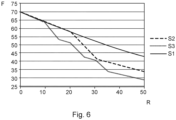
Fig. 6 ist eine Abhängigkeit der Fluidtemperatur von dem Radius R dargestellt. Für das erste Ausführungsbeispiel S1 vonFig. 4A ist eine lineare Abnahme der Fluidtemperatur vorhanden. Bei den Ausführungsbeispielen S2 und S3 ist eine stärkere Abnahme der Fluidtemperatur dargestellt, wobei insbesondere im Bereich der Querschnittsverengungen eine stärkere Absenkung der Fluidtemperatur noch vorhanden ist. - Gemäß einem Aspekt der vorliegenden Erfindung können die Querschnittsverengungen z. B. bei Kanalquerschnitten mit einer Fläche von 30.000 mm2 bis 100.000 mm2 verwendet werden.
-
- 100
- Windenergieanlage
- 102
- Turm
- 104
- Gondel
- 106
- Rotor
- 110
- Spinner
- 200
- Rotorblätter
- 203
- Innenvolumen
- 210
- Blattschalen
- 220
- Blattschalen
- 230
- Rotorblattvorderkante
- 231
- Stege
- 232
- Stege
- 240
- Rotorblatthinterkante
- 250
- Kanäle
- 260
- Kanäle
- 270
- Kanäle
- 310
- Querschnittsverengungen
- 320
- Querschnittsverengungen
- 330
- Querschnittsverengungen
- 500
- Rotorblattheizung
Claims (7)
- Windenergieanlagen-Rotorblatt (200), mit
einer Rotorblattschale (210, 220), welche ein Innenvolumen (203) umgibt, und mindestens einer Querschnittsverengung (300, 310, 320, 330) zur Verengung eines freien Querschnitts des Innenvolumens (203). - Windenergieanlagen-Rotorblatt (200) nach Anspruch 1, ferner mitmindestens einem Steg (231, 232) entlang einer Längsrichtung (L) des Rotorblattes (200),wobei die mindestens eine Querschnittsverengung (300, 310, 320, 330) an dem mindestens einen Steg (231, 232) angeordnet ist.
- Windenergieanlagen-Rotorblatt (200) nach Anspruch 1 oder 2, mitmindestens einem ersten und zweiten Steg (231, 232) entlang einer Längsachse (L) des Rotorblattes (200),einem ersten Luftkanal (250) zwischen einer Vorderkante (230) des Rotorblattes (200) und einem ersten Steg (231), wobei mindestens eine erste Querschnittsverengung (310) in dem ersten Luftkanal (250) vorgesehen ist.
- Windenergieanlagen-Rotorblatt (200) nach einem der Ansprüche 1 bis 3, mit
einem zweiten Luftkanal (260) zwischen einem Steg (231, 232) und einer Rotorblatthinterkante (240), wobei mindestens eine zweite Querschnittsverengung (320) zumindest teilweise in dem zweiten Luftkanal (260) entlang der Längsrichtung (L) des Rotorblattes (200) vorgesehen ist. - Windenergieanlagen-Rotorblatt (200) nach einem der Ansprüche 1 bis 4, mit
mindestens einer dritten Querschnittsverengung (330) in einem dritten Lüftungskanal (270) zwischen dem ersten und zweiten Steg (231, 232). - Windenergieanlagen-Rotorblatt (200) nach einem der Ansprüche 1 bis 5, ferner mit
einem Rotorblattheizsystem (500) in oder an einer Rotorblattwurzel (201) des Windenergieanlagen-Rotorblattes (200), wobei das Rotorblattheizsystem (500) erwärmte Luft erzeugt und in das Innenvolumen (203) des Rotorblattes (200) befördert. - Windenergieanlage (100) mit mindestens einem Windenergieanlagen-Rotorblatt (200) nach einem der Ansprüche 1 bis 6.
Priority Applications (3)
| Application Number | Priority Date | Filing Date | Title |
|---|---|---|---|
| EP21212511.6A EP4191053B1 (de) | 2021-12-06 | 2021-12-06 | Windenergieanlagen-rotorblatt |
| US18/060,511 US20230175493A1 (en) | 2021-12-06 | 2022-11-30 | Wind turbine rotor blade |
| CN202211548012.9A CN116221004A (zh) | 2021-12-06 | 2022-12-05 | 风能设施转子叶片 |
Applications Claiming Priority (1)
| Application Number | Priority Date | Filing Date | Title |
|---|---|---|---|
| EP21212511.6A EP4191053B1 (de) | 2021-12-06 | 2021-12-06 | Windenergieanlagen-rotorblatt |
Publications (3)
| Publication Number | Publication Date |
|---|---|
| EP4191053A1 true EP4191053A1 (de) | 2023-06-07 |
| EP4191053C0 EP4191053C0 (de) | 2025-02-26 |
| EP4191053B1 EP4191053B1 (de) | 2025-02-26 |
Family
ID=78821982
Family Applications (1)
| Application Number | Title | Priority Date | Filing Date |
|---|---|---|---|
| EP21212511.6A Active EP4191053B1 (de) | 2021-12-06 | 2021-12-06 | Windenergieanlagen-rotorblatt |
Country Status (3)
| Country | Link |
|---|---|
| US (1) | US20230175493A1 (de) |
| EP (1) | EP4191053B1 (de) |
| CN (1) | CN116221004A (de) |
Cited By (1)
| Publication number | Priority date | Publication date | Assignee | Title |
|---|---|---|---|---|
| EP4656870A1 (de) | 2024-05-27 | 2025-12-03 | Wobben Properties GmbH | Windenergieanlagen-rotorblatt |
Citations (3)
| Publication number | Priority date | Publication date | Assignee | Title |
|---|---|---|---|---|
| CN103511196A (zh) * | 2013-10-28 | 2014-01-15 | 长沙理工大学 | 一种风力发电机叶片的热气防冰装置 |
| WO2017021350A1 (de) | 2015-07-31 | 2017-02-09 | Wobben Properties Gmbh | Windenergieanlagen-rotorblatt |
| WO2018211055A1 (de) | 2017-05-18 | 2018-11-22 | Wobben Properties Gmbh | Windenergieanlagen-rotorblatt |
Family Cites Families (3)
| Publication number | Priority date | Publication date | Assignee | Title |
|---|---|---|---|---|
| DE102010051297B4 (de) * | 2010-11-12 | 2017-04-06 | Nordex Energy Gmbh | Rotorblatt einer Windenergieanlage |
| US11236733B2 (en) * | 2018-09-17 | 2022-02-01 | General Electric Company | Heating system and method for a jointed wind rotor turbine blade |
| EP4180654B1 (de) * | 2021-11-16 | 2025-02-26 | Wobben Properties GmbH | Windenergieanlagen-rotorblatt |
-
2021
- 2021-12-06 EP EP21212511.6A patent/EP4191053B1/de active Active
-
2022
- 2022-11-30 US US18/060,511 patent/US20230175493A1/en not_active Abandoned
- 2022-12-05 CN CN202211548012.9A patent/CN116221004A/zh active Pending
Patent Citations (3)
| Publication number | Priority date | Publication date | Assignee | Title |
|---|---|---|---|---|
| CN103511196A (zh) * | 2013-10-28 | 2014-01-15 | 长沙理工大学 | 一种风力发电机叶片的热气防冰装置 |
| WO2017021350A1 (de) | 2015-07-31 | 2017-02-09 | Wobben Properties Gmbh | Windenergieanlagen-rotorblatt |
| WO2018211055A1 (de) | 2017-05-18 | 2018-11-22 | Wobben Properties Gmbh | Windenergieanlagen-rotorblatt |
Cited By (1)
| Publication number | Priority date | Publication date | Assignee | Title |
|---|---|---|---|---|
| EP4656870A1 (de) | 2024-05-27 | 2025-12-03 | Wobben Properties GmbH | Windenergieanlagen-rotorblatt |
Also Published As
| Publication number | Publication date |
|---|---|
| CN116221004A (zh) | 2023-06-06 |
| EP4191053C0 (de) | 2025-02-26 |
| US20230175493A1 (en) | 2023-06-08 |
| EP4191053B1 (de) | 2025-02-26 |
Similar Documents
| Publication | Publication Date | Title |
|---|---|---|
| EP3625454B1 (de) | Windenergieanlagen-rotorblatt | |
| EP3329120B1 (de) | Windenergieanlagen-rotorblatt | |
| DE60025074T2 (de) | Methode zur Kühlung einer Wand einer Strömungsmaschinenschaufel | |
| DE102008028987A1 (de) | Turboproptriebwerk mit einer Vorrichtung zum Erzeugen eines Kühlluftstroms | |
| EP2984334B1 (de) | Rotorblatt einer windenergieanlage und windenergieanlage | |
| DE19802574A1 (de) | Windkraftanlage und Verfahren zum Betrieb einer Windkraftanlage | |
| DE102009029587A1 (de) | Rotor einer Turbomaschine | |
| WO2012164045A1 (de) | Rotor mit einem gekrümmten rotorblatt für eine windkraftanlage | |
| WO2000058606A1 (de) | Kühlmitteldurchströmte, gegossene gasturbinenschaufel sowie vorrichtung und verfahren zur herstellung eines verteilerraums der gasturbinenschaufel | |
| EP4191053B1 (de) | Windenergieanlagen-rotorblatt | |
| EP4306797B1 (de) | Windenergieanlagen-rotorblatt und windenergieanlage | |
| EP4180654B1 (de) | Windenergieanlagen-rotorblatt | |
| EP3963204B1 (de) | Rotor für eine windenergieanlage und windenergieanlage | |
| EP3109466A1 (de) | Windenergieanlagenrotorblatt mit einer elektrischen heizeinrichtung | |
| EP3399183B1 (de) | Rotorblatt einer windenergieanlage | |
| EP2304184A2 (de) | Gasturbine und verfahren zum ändern der aerodynamischen gestalt einer gasturbinenschaufel | |
| EP3735533B1 (de) | Verfahren zum steuern einer windenergieanlage sowie windenergieanlage | |
| EP3109465B1 (de) | Windenergieanlagenrotorblatt mit einer elektrischen heizeinrichtung | |
| EP4151856A1 (de) | Windenergieanlagen-rotorblatt | |
| EP4656870A1 (de) | Windenergieanlagen-rotorblatt | |
| EP4276300A1 (de) | Windenergieanlagen-rotorblatt und windenergieanlage | |
| DE10352789B4 (de) | Gasturbine | |
| EP4357605B1 (de) | Windenergieanlagen-rotorblatt und windenergieanlage | |
| EP4549732A1 (de) | Windenergieanlagen-rotorblatt | |
| EP4303436A1 (de) | Windenergieanlagen-rotorblatt und windenergieanlage |
Legal Events
| Date | Code | Title | Description |
|---|---|---|---|
| PUAI | Public reference made under article 153(3) epc to a published international application that has entered the european phase |
Free format text: ORIGINAL CODE: 0009012 |
|
| STAA | Information on the status of an ep patent application or granted ep patent |
Free format text: STATUS: THE APPLICATION HAS BEEN PUBLISHED |
|
| AK | Designated contracting states |
Kind code of ref document: A1 Designated state(s): AL AT BE BG CH CY CZ DE DK EE ES FI FR GB GR HR HU IE IS IT LI LT LU LV MC MK MT NL NO PL PT RO RS SE SI SK SM TR |
|
| STAA | Information on the status of an ep patent application or granted ep patent |
Free format text: STATUS: REQUEST FOR EXAMINATION WAS MADE |
|
| 17P | Request for examination filed |
Effective date: 20231207 |
|
| RBV | Designated contracting states (corrected) |
Designated state(s): AL AT BE BG CH CY CZ DE DK EE ES FI FR GB GR HR HU IE IS IT LI LT LU LV MC MK MT NL NO PL PT RO RS SE SI SK SM TR |
|
| STAA | Information on the status of an ep patent application or granted ep patent |
Free format text: STATUS: EXAMINATION IS IN PROGRESS |
|
| 17Q | First examination report despatched |
Effective date: 20240315 |
|
| REG | Reference to a national code |
Free format text: PREVIOUS MAIN CLASS: F03D0001060000 Ipc: F03D0080400000 Ref country code: DE Ref legal event code: R079 Ref document number: 502021006778 Country of ref document: DE |
|
| GRAP | Despatch of communication of intention to grant a patent |
Free format text: ORIGINAL CODE: EPIDOSNIGR1 |
|
| STAA | Information on the status of an ep patent application or granted ep patent |
Free format text: STATUS: GRANT OF PATENT IS INTENDED |
|
| RIC1 | Information provided on ipc code assigned before grant |
Ipc: F03D 1/06 20060101ALI20241016BHEP Ipc: F03D 80/40 20160101AFI20241016BHEP |
|
| INTG | Intention to grant announced |
Effective date: 20241028 |
|
| GRAS | Grant fee paid |
Free format text: ORIGINAL CODE: EPIDOSNIGR3 |
|
| GRAA | (expected) grant |
Free format text: ORIGINAL CODE: 0009210 |
|
| STAA | Information on the status of an ep patent application or granted ep patent |
Free format text: STATUS: THE PATENT HAS BEEN GRANTED |
|
| AK | Designated contracting states |
Kind code of ref document: B1 Designated state(s): AL AT BE BG CH CY CZ DE DK EE ES FI FR GB GR HR HU IE IS IT LI LT LU LV MC MK MT NL NO PL PT RO RS SE SI SK SM TR |
|
| REG | Reference to a national code |
Ref country code: GB Ref legal event code: FG4D Free format text: NOT ENGLISH |
|
| RIN1 | Information on inventor provided before grant (corrected) |
Inventor name: KREBS, SVEN Inventor name: GODENAU, DIETHELM Inventor name: MAHMOUD, MUHANAD |
|
| REG | Reference to a national code |
Ref country code: CH Ref legal event code: EP |
|
| REG | Reference to a national code |
Ref country code: DE Ref legal event code: R096 Ref document number: 502021006778 Country of ref document: DE |
|
| REG | Reference to a national code |
Ref country code: IE Ref legal event code: FG4D Free format text: LANGUAGE OF EP DOCUMENT: GERMAN |
|
| U01 | Request for unitary effect filed |
Effective date: 20250226 |
|
| U07 | Unitary effect registered |
Designated state(s): AT BE BG DE DK EE FI FR IT LT LU LV MT NL PT RO SE SI Effective date: 20250306 |
|
| PG25 | Lapsed in a contracting state [announced via postgrant information from national office to epo] |
Ref country code: RS Free format text: LAPSE BECAUSE OF FAILURE TO SUBMIT A TRANSLATION OF THE DESCRIPTION OR TO PAY THE FEE WITHIN THE PRESCRIBED TIME-LIMIT Effective date: 20250526 |
|
| PG25 | Lapsed in a contracting state [announced via postgrant information from national office to epo] |
Ref country code: PL Free format text: LAPSE BECAUSE OF FAILURE TO SUBMIT A TRANSLATION OF THE DESCRIPTION OR TO PAY THE FEE WITHIN THE PRESCRIBED TIME-LIMIT Effective date: 20250226 |
|
| PG25 | Lapsed in a contracting state [announced via postgrant information from national office to epo] |
Ref country code: ES Free format text: LAPSE BECAUSE OF FAILURE TO SUBMIT A TRANSLATION OF THE DESCRIPTION OR TO PAY THE FEE WITHIN THE PRESCRIBED TIME-LIMIT Effective date: 20250226 |
|
| PG25 | Lapsed in a contracting state [announced via postgrant information from national office to epo] |
Ref country code: NO Free format text: LAPSE BECAUSE OF FAILURE TO SUBMIT A TRANSLATION OF THE DESCRIPTION OR TO PAY THE FEE WITHIN THE PRESCRIBED TIME-LIMIT Effective date: 20250526 Ref country code: IS Free format text: LAPSE BECAUSE OF FAILURE TO SUBMIT A TRANSLATION OF THE DESCRIPTION OR TO PAY THE FEE WITHIN THE PRESCRIBED TIME-LIMIT Effective date: 20250626 |
|
| PG25 | Lapsed in a contracting state [announced via postgrant information from national office to epo] |
Ref country code: HR Free format text: LAPSE BECAUSE OF FAILURE TO SUBMIT A TRANSLATION OF THE DESCRIPTION OR TO PAY THE FEE WITHIN THE PRESCRIBED TIME-LIMIT Effective date: 20250226 |
|
| PG25 | Lapsed in a contracting state [announced via postgrant information from national office to epo] |
Ref country code: GR Free format text: LAPSE BECAUSE OF FAILURE TO SUBMIT A TRANSLATION OF THE DESCRIPTION OR TO PAY THE FEE WITHIN THE PRESCRIBED TIME-LIMIT Effective date: 20250527 |
|
| PG25 | Lapsed in a contracting state [announced via postgrant information from national office to epo] |
Ref country code: SM Free format text: LAPSE BECAUSE OF FAILURE TO SUBMIT A TRANSLATION OF THE DESCRIPTION OR TO PAY THE FEE WITHIN THE PRESCRIBED TIME-LIMIT Effective date: 20250226 |
|
| PG25 | Lapsed in a contracting state [announced via postgrant information from national office to epo] |
Ref country code: CZ Free format text: LAPSE BECAUSE OF FAILURE TO SUBMIT A TRANSLATION OF THE DESCRIPTION OR TO PAY THE FEE WITHIN THE PRESCRIBED TIME-LIMIT Effective date: 20250226 |
|
| PG25 | Lapsed in a contracting state [announced via postgrant information from national office to epo] |
Ref country code: SK Free format text: LAPSE BECAUSE OF FAILURE TO SUBMIT A TRANSLATION OF THE DESCRIPTION OR TO PAY THE FEE WITHIN THE PRESCRIBED TIME-LIMIT Effective date: 20250226 |
|
| PLBE | No opposition filed within time limit |
Free format text: ORIGINAL CODE: 0009261 |
|
| STAA | Information on the status of an ep patent application or granted ep patent |
Free format text: STATUS: NO OPPOSITION FILED WITHIN TIME LIMIT |
|
| U20 | Renewal fee for the european patent with unitary effect paid |
Year of fee payment: 5 Effective date: 20251128 |
|
| 26N | No opposition filed |
Effective date: 20251127 |