EP4190647A1 - Occupant restraint device - Google Patents
Occupant restraint device Download PDFInfo
- Publication number
- EP4190647A1 EP4190647A1 EP21850649.1A EP21850649A EP4190647A1 EP 4190647 A1 EP4190647 A1 EP 4190647A1 EP 21850649 A EP21850649 A EP 21850649A EP 4190647 A1 EP4190647 A1 EP 4190647A1
- Authority
- EP
- European Patent Office
- Prior art keywords
- airbag
- tensile
- occupant
- restraining device
- cloths
- Prior art date
- Legal status (The legal status is an assumption and is not a legal conclusion. Google has not performed a legal analysis and makes no representation as to the accuracy of the status listed.)
- Pending
Links
Images








Classifications
-
- B—PERFORMING OPERATIONS; TRANSPORTING
- B60—VEHICLES IN GENERAL
- B60R—VEHICLES, VEHICLE FITTINGS, OR VEHICLE PARTS, NOT OTHERWISE PROVIDED FOR
- B60R21/00—Arrangements or fittings on vehicles for protecting or preventing injuries to occupants or pedestrians in case of accidents or other traffic risks
- B60R21/02—Occupant safety arrangements or fittings, e.g. crash pads
- B60R21/16—Inflatable occupant restraints or confinements designed to inflate upon impact or impending impact, e.g. air bags
- B60R21/23—Inflatable members
- B60R21/231—Inflatable members characterised by their shape, construction or spatial configuration
- B60R21/23138—Inflatable members characterised by their shape, construction or spatial configuration specially adapted for side protection
-
- B—PERFORMING OPERATIONS; TRANSPORTING
- B60—VEHICLES IN GENERAL
- B60R—VEHICLES, VEHICLE FITTINGS, OR VEHICLE PARTS, NOT OTHERWISE PROVIDED FOR
- B60R21/00—Arrangements or fittings on vehicles for protecting or preventing injuries to occupants or pedestrians in case of accidents or other traffic risks
- B60R21/02—Occupant safety arrangements or fittings, e.g. crash pads
- B60R21/16—Inflatable occupant restraints or confinements designed to inflate upon impact or impending impact, e.g. air bags
- B60R21/20—Arrangements for storing inflatable members in their non-use or deflated condition; Arrangement or mounting of air bag modules or components
- B60R21/207—Arrangements for storing inflatable members in their non-use or deflated condition; Arrangement or mounting of air bag modules or components in vehicle seats
-
- B—PERFORMING OPERATIONS; TRANSPORTING
- B60—VEHICLES IN GENERAL
- B60R—VEHICLES, VEHICLE FITTINGS, OR VEHICLE PARTS, NOT OTHERWISE PROVIDED FOR
- B60R21/00—Arrangements or fittings on vehicles for protecting or preventing injuries to occupants or pedestrians in case of accidents or other traffic risks
- B60R21/02—Occupant safety arrangements or fittings, e.g. crash pads
- B60R21/16—Inflatable occupant restraints or confinements designed to inflate upon impact or impending impact, e.g. air bags
- B60R21/23—Inflatable members
- B60R21/231—Inflatable members characterised by their shape, construction or spatial configuration
- B60R21/233—Inflatable members characterised by their shape, construction or spatial configuration comprising a plurality of individual compartments; comprising two or more bag-like members, one within the other
-
- B—PERFORMING OPERATIONS; TRANSPORTING
- B60—VEHICLES IN GENERAL
- B60R—VEHICLES, VEHICLE FITTINGS, OR VEHICLE PARTS, NOT OTHERWISE PROVIDED FOR
- B60R21/00—Arrangements or fittings on vehicles for protecting or preventing injuries to occupants or pedestrians in case of accidents or other traffic risks
- B60R21/02—Occupant safety arrangements or fittings, e.g. crash pads
- B60R21/16—Inflatable occupant restraints or confinements designed to inflate upon impact or impending impact, e.g. air bags
- B60R21/23—Inflatable members
- B60R21/231—Inflatable members characterised by their shape, construction or spatial configuration
- B60R21/2334—Expansion control features
- B60R21/2338—Tethers
-
- B—PERFORMING OPERATIONS; TRANSPORTING
- B60—VEHICLES IN GENERAL
- B60R—VEHICLES, VEHICLE FITTINGS, OR VEHICLE PARTS, NOT OTHERWISE PROVIDED FOR
- B60R21/00—Arrangements or fittings on vehicles for protecting or preventing injuries to occupants or pedestrians in case of accidents or other traffic risks
- B60R21/02—Occupant safety arrangements or fittings, e.g. crash pads
- B60R21/16—Inflatable occupant restraints or confinements designed to inflate upon impact or impending impact, e.g. air bags
- B60R21/23—Inflatable members
- B60R21/231—Inflatable members characterised by their shape, construction or spatial configuration
- B60R21/23138—Inflatable members characterised by their shape, construction or spatial configuration specially adapted for side protection
- B60R2021/23146—Inflatable members characterised by their shape, construction or spatial configuration specially adapted for side protection seat mounted
-
- B—PERFORMING OPERATIONS; TRANSPORTING
- B60—VEHICLES IN GENERAL
- B60R—VEHICLES, VEHICLE FITTINGS, OR VEHICLE PARTS, NOT OTHERWISE PROVIDED FOR
- B60R21/00—Arrangements or fittings on vehicles for protecting or preventing injuries to occupants or pedestrians in case of accidents or other traffic risks
- B60R21/02—Occupant safety arrangements or fittings, e.g. crash pads
- B60R21/16—Inflatable occupant restraints or confinements designed to inflate upon impact or impending impact, e.g. air bags
- B60R21/23—Inflatable members
- B60R21/231—Inflatable members characterised by their shape, construction or spatial configuration
- B60R21/233—Inflatable members characterised by their shape, construction or spatial configuration comprising a plurality of individual compartments; comprising two or more bag-like members, one within the other
- B60R2021/23324—Inner walls crating separate compartments, e.g. communicating with vents
-
- B—PERFORMING OPERATIONS; TRANSPORTING
- B60—VEHICLES IN GENERAL
- B60R—VEHICLES, VEHICLE FITTINGS, OR VEHICLE PARTS, NOT OTHERWISE PROVIDED FOR
- B60R21/00—Arrangements or fittings on vehicles for protecting or preventing injuries to occupants or pedestrians in case of accidents or other traffic risks
- B60R21/02—Occupant safety arrangements or fittings, e.g. crash pads
- B60R21/16—Inflatable occupant restraints or confinements designed to inflate upon impact or impending impact, e.g. air bags
- B60R21/23—Inflatable members
- B60R21/231—Inflatable members characterised by their shape, construction or spatial configuration
- B60R21/233—Inflatable members characterised by their shape, construction or spatial configuration comprising a plurality of individual compartments; comprising two or more bag-like members, one within the other
- B60R2021/23324—Inner walls crating separate compartments, e.g. communicating with vents
- B60R2021/23332—Inner walls crating separate compartments, e.g. communicating with vents using independent bags, one within the other
-
- B—PERFORMING OPERATIONS; TRANSPORTING
- B60—VEHICLES IN GENERAL
- B60R—VEHICLES, VEHICLE FITTINGS, OR VEHICLE PARTS, NOT OTHERWISE PROVIDED FOR
- B60R21/00—Arrangements or fittings on vehicles for protecting or preventing injuries to occupants or pedestrians in case of accidents or other traffic risks
- B60R21/02—Occupant safety arrangements or fittings, e.g. crash pads
- B60R21/16—Inflatable occupant restraints or confinements designed to inflate upon impact or impending impact, e.g. air bags
- B60R21/23—Inflatable members
- B60R21/231—Inflatable members characterised by their shape, construction or spatial configuration
- B60R21/2334—Expansion control features
- B60R21/2338—Tethers
- B60R2021/23382—Internal tether means
-
- B—PERFORMING OPERATIONS; TRANSPORTING
- B60—VEHICLES IN GENERAL
- B60R—VEHICLES, VEHICLE FITTINGS, OR VEHICLE PARTS, NOT OTHERWISE PROVIDED FOR
- B60R21/00—Arrangements or fittings on vehicles for protecting or preventing injuries to occupants or pedestrians in case of accidents or other traffic risks
- B60R21/02—Occupant safety arrangements or fittings, e.g. crash pads
- B60R21/16—Inflatable occupant restraints or confinements designed to inflate upon impact or impending impact, e.g. air bags
- B60R21/23—Inflatable members
- B60R21/231—Inflatable members characterised by their shape, construction or spatial configuration
- B60R21/2334—Expansion control features
- B60R21/2338—Tethers
- B60R2021/23386—External tether means
-
- B—PERFORMING OPERATIONS; TRANSPORTING
- B60—VEHICLES IN GENERAL
- B60R—VEHICLES, VEHICLE FITTINGS, OR VEHICLE PARTS, NOT OTHERWISE PROVIDED FOR
- B60R21/00—Arrangements or fittings on vehicles for protecting or preventing injuries to occupants or pedestrians in case of accidents or other traffic risks
- B60R21/02—Occupant safety arrangements or fittings, e.g. crash pads
- B60R21/16—Inflatable occupant restraints or confinements designed to inflate upon impact or impending impact, e.g. air bags
- B60R21/23—Inflatable members
- B60R21/231—Inflatable members characterised by their shape, construction or spatial configuration
- B60R21/2334—Expansion control features
- B60R21/2338—Tethers
- B60R2021/23386—External tether means
- B60R2021/23388—External tether means having ends which are movable or detachable during deployment
Definitions
- the present invention relates to an occupant restraining device provided with an airbag.
- This application claims priority based on Japanese Application 2020-127516 filed July 28, 2020 , which is incorporated by reference in its entirety.
- Airbag devices have become widely used in recent years.
- An airbag device is a restraining device that operates in the case of an emergency such as a vehicle collision and, for example, the airbag is expanded and deployed by gas pressure to protect the occupant.
- Patent Document 1 discloses side airbag devices that are provided on both sides of a vehicle seat and expand and deploy to the sides of the occupant.
- Patent Document 1 Japanese Unexamined Patent Application 2014-034356
- the airbag in order for the airbag to expand and deploy in order to receive the occupant, the airbag needs to be positioned at an expected position. Therefore, a technique for adjusting the position of an expanding and deploying airbag using a tensile cloth is also known. With this manner of technique, when the airbag expands and deploys, the tensile cloth surrounds and retains the outside of the airbag and biases the airbag to the side of the occupant.
- an object of the present invention is to provide an occupant restraining device in which the tensile cloth can more accurately adjust the position of the airbag when the airbag is expanded and deployed.
- the occupant restraining device includes:
- the airbag when the airbag expands and deploys, the airbag can be more accurately positioned.
- the occupant restraining device according to the Embodiment of the present invention will be described in detail below according to the diagrams.
- the occupant restraining device according to the embodiment of the present invention is equipped to a seat of a vehicle.
- FIG. 1 is a diagram illustrating a state in which the occupant restraining device 100 according to Embodiment 1 is attached to a vehicle seat 5.
- FIG. 1 illustrates a state before the airbag expands and deploys. For convenience, descriptions will be given in the following using each of the front-to-back, left-right, and up-down directions defined in the figures.
- the seat 5 includes the seat cushion 8 on which the occupant sits, and a seatback 4 that stands up from the back side of the seat cushion 8 and supports the back of the occupant.
- the lower edge of the seatback 4 is provided at the rear edge of the seat cushion 8, and is rotatably retained by a shaft 6. Accordingly, the seatback 4 can be adjusted at an angle by rotating the shaft 6 in the front-to-back direction.
- a headrest part 7 is provided in the center in the left-right direction on the upper part of the seatback 4 rising up from the seatback 4.
- the headrest part 7 supports the head of the occupant seated on the seat cushion 8.
- the occupant restraining device 100 includes airbag modules 1a and 1b containing an airbag stowed within the housing and tensile cloths 2a and 2b that perform position adjustment of the airbag that expands and deploys.
- the airbag module 1a is provided on the left side of the seatback 4, and the airbag module 1b is provided on the right side of the seatback 4.
- the airbag modules 1a and 1b are arranged between the frame (not shown) inside the seatback 4 and the cover covering the frame.
- FIG. 1 illustrates a case where an airbag module 1b is provided on the right side of the seatback 4 and an airbag module 1a is provided on the left side of the seatback 4, but the present invention is not limited to this and the airbag modules 1a and 1b may be provided on only one side.
- Each of the airbag modules 1a and 1b includes an airbag 3 (see FIG. 2 ), and an inflator (not shown) that emits gas into the airbag 3.
- the airbag 3 is formed by sewing the outer edges of two panels together, with, for example, the aforementioned inflator arranged inside the airbag 3.
- the occupant restraining device 100 protects the occupants through expansion and deployment of the airbag 3 in the forward direction and receiving the occupant.
- the tensile cloths 2a and 2b are illustrated by an alternate long and short dashed line.
- Tensile cloths 2a and 2b are strips of prescribed width, with the tensile cloth 2a being provided on the left side of the seatback 4 and the tensile cloth 2b being provided on the right side of the seatback 4.
- the upper end part 21a is secured to a securing position F1 of the seatback 4 frame on the left side of the headrest part 7 that is the upper surface 41 of the seatback 4.
- the upper end part 21b is secured to a securing position F2 of the seatback 4 frame on the right side of the headrest part 7 that is the upper surface 41 of the seatback 4.
- the lower securing part 81 includes, for example, two metal plates, and the lower end parts 22a and 22b of the tensile cloths 2a and 2b are sandwiched between such metal plates.
- the tensile cloths 2a and 2b are arranged inside these side parts from the seatback 4 to the seat cushion 8.
- the tensile cloth 2a is arranged from the left side of the seatback 4 to the left side of the seat cushion 8, and the tensile cloth 2b is arranged from the right side of the seatback 4 to the right side of the seat cushion 8.
- Each of the tensile cloths 2a and 2b has the middle section thereof passing through the airbag modules 1a and 1b, and are joined to each airbag 3 in the airbag modules 1a and 1b as described below.
- the airbag 3 instantly breaks the cover of the seatback 4 and expands and deploys toward the front of the seat 5.
- the tensile cloths 2a and 2b burst out from both side parts of the seat 5 together with the airbag 3 to retain the expanding and deploying airbag 3, enabling arranging the airbag 3 at the center of the seatback 4, in other words, the occupant side of the seat cushion 8.
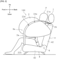
- FIG. 2 is a schematic diagram illustrating a state in which an airbag 3 of the occupant restraining device 100 is expanded and deployed.
- FIG. 2 illustrates only the expansion and deployment of the airbag 3 on the left side of the occupant P seated on the seat cushion 8.
- the airbag 3 expands and deploys similarly on both the left and right sides of the occupant P, where position adjustment of the airbag 3 on the left side is performed by the tensile cloth 2a, and position adjustment of the airbag 3 on the right side is performed by the tensile cloth 2b (see FIG. 3 ). Therefore, a description of the action and movement of the tensile cloth 2a on the left side of the seat 5 will be described using FIG. 2 , and the description of the tensile cloth 2b will be omitted.
- the airbag 3 on the left side breaks the cover from the inside of the side surface 42 of the seatback 4 and expands and deploys toward the front of the seat 5.
- the tensile cloth 2a also bursts out and surrounds the outside of the expanding and deploying airbag 3, which is then arranged to the center of the seatback 4, in other words, where the occupant P is sitting on the seat cushion 8, and holds and restrains the occupant P to protect the occupant P.
- the tensile cloth 2a inevitably comes into partial contact with the outer surface of the airbag 3.
- a prescribed location of the contact area between the airbag 3 and the tensile cloth 2a is sewn together to join the tensile cloth 2a to the airbag 3.
- the tensile cloth 2a is sewn to the airbag 3 at two joint sections 23a and 24a indicated by an "X".
- the joint section 23a is positioned below the joint section 24a.
- a retaining groove 9a that retains the tensile cloth 2a is provided below the joint section 23a and on the lower part of the airbag 3.
- the retaining groove 9a receives and retains the tensile cloth 2a when the airbag 3 expands and deploys, preventing the airbag 3 from leaving the normal position thereof.
- the lower part of the airbag 3 means from the lower end part of the expanded and deployed airbag 3 to the part of the airbag 3 that is most inflated in the vehicle width direction.
- the section of the airbag 3 lower than the center in the vertical direction is illustrated in general, but is not limited thereto.
- the upper part of the airbag 3 is defined as from the upper end part of the expanded and deployed airbag 3 to the part of the airbag 3 that is most inflated in the vehicle width direction.
- the section of the airbag 3 higher than the center in the vertical direction is illustrated in general, but is not limited thereto.
- the most inflated part of the airbag 3 in the vehicle width direction is the most inflated part in the contact area where the expanded and deployed airbag 3 contacts the tensile cloths 2a and 2b, and may differ from the most inflated part of the entire airbag 3.
- FIG. 3 is an enlarged view of the expanded and deployed airbag 3.
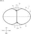
- FIG. 4 is a cross-sectional view of the airbag 3 along the line IV-IV in FIG. 3 .
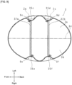
- FIG. 5 is a cross-sectional view of the airbag 3 along the line V-V in FIG. 3 .
- FIG. 4 is a view from below.
- the occupant P is illustrated as a double-dashed line for convenience of explanation.
- the tensile cloth 2a is illustrated as a double-dashed line for convenience.
- FIG. 6 is a cross-sectional view of the airbag 3 along line VI-VI in FIG. 5 .
- the tensile cloth 2a is illustrated by a dashed line.
- the airbag 3 is a bag body formed by joining a first panel 3a (contact section) and a second panel 3b (non-contact section) of the same approximate shape by sewing the perimeters together.
- the first panel 3a and second panel 3b are, for example, circular. Therefore, the airbag 3 is restricted by a seam 34 during expansion and deployment, and when the expansion and deployment is complete, the airbag 3 has a substantially elliptic shape in the longitudinal and transverse sections.
- the first panel 3a and the second panel 3b face each other, with the first panel 3a joined to the tensile cloth 2a as described above and the second panel 3b facing the occupant P.
- the seam 34 of the airbag 3 is illustrated by an alternate long and short dashed line.
- the airbag 3 is also equipped with an internal tether 32 that controls the shape of the airbag 3 during expansion and deployment. Furthermore, the lower part of the airbag 3 has a retaining groove 9a in the first panel 3a and a groove 9b in the second panel 3b, as described below. The retaining groove 9a and groove 9b are formed by the internal tether 32. For the sake of explanation, the case in which the airbag 3 is expanded and deployed will be used below.
- the internal tether 32 is provided inside the airbag 3.
- the internal tether 32 has a substantially trapezoidal sheet shape, with the shorter of the two substantially parallel sides on the lower side and the longer side on the upper side, and is located at the lower part of the airbag 3 (see FIG. 5 ).
- the internal tether 32 is provided at a prescribed distance from the bottom edge of the airbag 3.
- the internal tether 32 is constructed between the first panel 3a and the second panel 3b.
- One of the two sides adjacent to the aforementioned short side of the internal tether 32 is sewn to the bottom of the first panel 3a and the other is sewn to the bottom of the second panel 3b. This forms a seam 35a in the first panel 3a and a seam 35b in the second panel 3b (see FIG. 3 and FIG. 4 ).
- the inside of the first panel 3a and second panel 3b are restrained by the internal tether 32, so that the airbag 3 is restricted from expanding in the direction opposite the first panel 3a and second panel 3b (hereafter, the thickness direction of the airbag 3) during expansion and deployment.
- first panel 3a is joined to the internal tether 32 at the lower seam 35a and the second panel 3b is joined to the internal tether 32 at the lower seam 35b.
- first panel 3a other sections can expand relatively freely except for the section corresponding to seam 35a
- second panel 3b other sections can expand relatively freely except for the section corresponding to seam 35b.
- the lower part of the first panel 3a and the lower part of the second panel 3b pull against each other via the internal tether 32, so that in the first panel 3a, the area pertaining to seam 35a and the area around seam 35a, and in the second panel 3b, the area pertaining to seam 35b and the area around seam 35b, are concave.
- a retaining groove 9a is formed in the section corresponding to the internal tether 32 (seam 35a).
- a groove 9b is formed in the area corresponding to the internal tether 32 (seam 35b) (see FIG. 4 ).
- the outside of the area enclosed by the dashed line corresponds to retaining groove 9a and groove 9b.
- the internal tether 32 is a substantially trapezoidal shape and has a prescribed dimension in the height direction. Therefore, seams 35a and 35b are formed in the vertical direction and over a prescribed range. Thus, the retaining groove 9a and groove 9b extend in the vertical direction and over a prescribed range. Furthermore, since the internal tether 32 has a substantially trapezoidal shape, the dimensions thereof in the direction that intersects said height direction (hereinafter referred to as the width direction) gradually decrease in the downward direction.
- the periphery of the seam 35a in the first panel 3a and the periphery of the seam 35b in the second panel 3b are recessed, and the dimension of the internal tether 32 in the width direction gradually decreases in the downward direction.
- the retaining groove 9a of the first panel 3a, and the groove 9b of the second panel 3b are connected, forming a recessed section 36 at the bottom end of the airbag 3.
- a retaining groove 9a is formed in the lower part of the first panel 3a that contacts the tensile cloth 2a during expansion and deployment of the airbag 3, extending in the vertical direction.
- the tensile cloth 2a is received in the retaining groove 9a (see FIG. 4 ).
- both edges in the width direction are in contact with the first panel 3a in the retaining groove 9a, whereas excluding the edges, there is a gap between the center thereof and the first panel 3a.
- the tensile cloth 2a can slide along the length of the retaining groove 9a on the first panel 3a within the retaining groove 9a (see FIG. 6 ).
- the tensile cloth 2a is restricted from moving in the width direction of the retaining groove 9a. Therefore, during expansion and deployment, the lower part of the airbag 3 can be prevented from separating from the tensile cloth 2a and deviating from the anticipated position, and the tensile cloth 2a can reliably apply bias to the airbag 3 and adjust the position thereof toward the occupant P.
- the location of the internal tether 32 is not limited to the positions illustrated in FIG. 4 to FIG. 6 .
- the internal tether 32 is provided such that the retaining groove 9a is formed at a position causing the tensile cloth 2a to suitably bias the expanding and deploying airbag 3 toward the occupant P.
- the internal tether 32 has a substantially trapezoidal shape, and the dimension thereof in the width direction gradually decreases in the downward direction.
- the lower end part 22a of the tensile cloth 2a is retained in the lower securing part 81 on the center side of the front of the seat cushion 8 (see FIG. 1 ). That is, the closer the retaining groove 9a is to the lower end of the airbag 3, the closer it is to the lower end part 22a of the tensile cloth 2a (lower securing part 81). Therefore, the tensile cloth 2a is easily received in the retaining groove 9a during the expansion and deployment of the airbag 3.
- the retaining groove 9a is provided at the lower part of the airbag 3 and a recessed section 36 is formed in the lower end part of the airbag 3, when the airbag 3 expands and deploys, the tensile cloth 2a is caught in the retaining groove 9a and recessed section 36 to lift and position the airbag 3 more precisely to the desired position closer to the head of the occupant P.
- the position of the expanding and deploying airbag 3 can be more stably adjusted.
- tensile cloth 2a has two joint sections 23a and 24a
- the joint sections 23a and 24a are not required and may be omitted.
- the tensile cloth 2a has two joint sections 23a and 24a has been described as an example, but is not limited thereto.
- a joint section may be at one location or at three or more locations.
- each of the joint sections 23a and 24a may be provided over a prescribed range along the longitudinal direction of the tensile cloth 2a.
- the tensile cloths 2a and 2b are sewn to the airbag 3 has been described as an example, but is not limited thereto.
- the tensile cloth 2a may be fixed to the airbag 3 by an adhesive, or may be fixed using a surface fastener or the like.
- the tensile cloths 2a and 2b may be a wide cloth or a large area of cloth.
- Embodiment 1 a case where one of the tensile cloths 2a and 2b is provided for each airbag 3 has been described as an example, but is not limited thereto.
- FIG. 7 is a schematic diagram illustrating a state in which an airbag 3 of the occupant restraining device 100 according to Embodiment 2 is expanded and deployed.
- FIG. 7 for convenience, expansion and deployment of only the airbag 3 on the left side of the occupant P is illustrated, however in actuality, the airbag 3 expands and deploys in the same manner on both the left and right sides of the occupant P.
- position adjustment is performed by the tensile cloths 2a and 2c on the left side airbag 3
- position adjustment is performed by the tensile cloths 2b and 2d on the right side airbag 3 (see FIG. 8 ).
- FIG. 7 an example of expansion and deployment of only the airbag 3 on the left side of the occupant P will be described with reference to FIG. 7 .
- the upper end part 21a of the tensile cloth 2a and the upper end part 21c of the tensile cloth 2c are secured to the upper part of the seatback 4.
- a lower end part 22a of the tensile cloth 2a and a lower end part 22c of the tensile cloth 2c are retained by the lower securing part 81 at the front center section of the seat cushion 8 (see FIG. 1 ).
- the tensile cloths 2a and 2c are arranged together at the left side of the seat 5.
- the tensile cloth 2a has two joint sections 23a and 24a
- the tensile cloth 2c has two joint sections 23c and 24c.
- the joint section 23a and joint section 24a the joint section 23a is positioned lower than the joint section 24a and of the joint section 23c and the joint section 24c
- the joint section 23c is positioned lower than the joint section 24c.
- a retaining groove 9c is provided below the joint section 23a of the tensile cloth 2a and below the lower part of the airbag 3 to receive and retain the tensile cloth 2a during expansion and deployment of the airbag 3.
- the retaining groove 9d is provided below the joint section 23c of the tensile cloth 2c and below the lower part of the airbag 3 to receive and retain the tensile cloth 2c during expansion and deployment of the airbag 3.
- the retaining grooves 9c and 9d receive and retain the tensile cloths 2a and 2c respectively when the airbag 3 expands and deploys, preventing the airbag 3 from deviating from the anticipated position thereof.
- FIG. 8 is an enlarged view of the expanded and deployed airbag 3.
- FIG. 9 is a cross-sectional view of the airbag 3 along line IX-IX in FIG. 8 .
- FIG. 10 is a longitudinal cross-sectional view of the airbag 3 along line X-X in FIG. 8 .
- FIG. 9 is a view from below.
- the occupant P is illustrated as a double-dashed line for convenience of explanation.
- FIG. 11 is a longitudinal cross-sectional view of the airbag 3 along line XI-XI in FIG. 10 .
- the tensile cloths 2a and 2c are illustrated as dotted lines in FIG. 8 and FIG. 9 and as dashed lines in FIG. 11 .
- Airbag 3 is a bag body formed by joining a first panel 3a and a second panel 3b of the same shape by sewing the perimeters together.
- the first panel 3a and second panel 3b are, for example, circular. Therefore, the airbag 3 is restricted by a seam 34 during expansion and deployment, and when the expansion and deployment is complete, the airbag 3 has a substantially elliptic shape in the longitudinal and transverse sections.
- the first panel 3a and the second panel 3b face each other, with the first panel 3a joined to the tensile cloths 2a and 2c and the second panel 3b facing the occupant P.
- the seam 34 of the airbag 3 is illustrated by an alternate long and short dashed line.
- the airbag 3 has internal tethers 32a and 32b.
- the lower part of the airbag 3 has retaining grooves 9c and 9d in the first panel 3a and grooves 9e and 9f in the second panel 3b, as described below. Retaining grooves 9c and 9d and grooves 9e and 9f are formed by the internal tethers 32a and 32b.
- the case in which the airbag 3 is expanded and deployed will be used below.
- the internal tethers 32a and 32b are provided inside the airbag 3.
- the internal tethers 32a and 32b have a substantially trapezoidal sheet shape, with the shorter of the two substantially parallel sides on the lower side and the longer side on the upper side, and are located at the lower part of the airbag 3 (see FIG. 10 ).
- the internal tethers 32a and 32b are spaced at a prescribed distance from the bottom edge of the airbag 3.
- the internal tethers 32a and 32b are spaced at prescribed intervals in the front-to-back direction.
- the internal tethers 32a and 32b are constructed between the first panel 3a and the second panel 3b.
- One of the two sides adjacent to the aforementioned short side of the internal tethers 32a and 32b is sewn to the bottom of the first panel 3a and the other is sewn to the bottom of the second panel 3b.
- Seams 35c and 35d are formed in the first panel 3a and seams 35e and 35f are formed in the second panel 3b (see FIG. 8 and FIG. 9 ).
- the inner sides of the first panel 3a and second panel 3b are restrained by the internal tethers 32a and 32b, so that the airbag 3 is restricted from expanding in the thickness direction during expansion and deployment.
- first panel 3a is joined to the internal tethers 32a and 32b at the lower seams 35c and 35d
- the second panel 3b is joined to the internal tethers 32a and 32b at the lower seams 35e and 35f.
- first panel 3a other sections can expand relatively freely except for the sections corresponding to seams 35c and 35d
- second panel 3b other sections can expand relatively freely except for the sections corresponding to seams 35e and 35f.
- the lower part of the first panel 3a and the lower part of the second panel 3b pull against each other via the internal tethers 32a and 32b, so that in the first panel 3a, the area pertaining to the seams 35c and 35d and the area around the seams 35c and 35d are concave, and in the second panel 3b, the area pertaining to the seams 35e and 35f and the area around the seams 35e and 35f are concave.
- the retaining grooves 9c and 9d are formed in the sections corresponding to the internal tethers 32a and 32b (seams 35c and 35d), respectively.
- grooves 9e and 9f are also formed in the section corresponding to the internal tethers 32a and 32b (seams 35e and 35f) (see FIG. 9 ).
- the outside of the regions A and C surrounded by dashed lines correspond to the retaining grooves 9c and 9d, respectively, and the outside of the regions B and D surrounded by dashed lines correspond to the grooves 9e and 9f, respectively.
- each of the internal tethers 32a and 32b have a substantially trapezoidal shape, so seams 35c, 35d and 35e, 35f are formed in the vertical direction and over a prescribed range.
- the retaining grooves 9c, 9d and 9e, 9f extend in the vertical direction and over a prescribed range.
- the internal tethers 32a and 32b are substantially trapezoidal in shape, the dimensions thereof in the width direction gradually decrease in the downward direction.
- the areas around the seams 35c and 35d in the first panel 3a and around the seams 35e and 35f in the second panel 3b are concave, and the dimensions of the internal tethers 32a and 32b in the width direction gradually decrease in the downward direction.
- the retaining grooves 9c and 9d of the first panel 3a and grooves 9e and 9f of the second panel 3b are connected, and two recessed sections 36a and 36b are formed at the lower end part of the airbag 3.
- retaining grooves 9c and 9d are formed in the first panel 3a extending in the vertical direction during expansion and deployment of the airbag 3.
- the tensile cloths 2a and 2c are received in the retaining grooves 9c and 9d (see FIG. 9 ).
- both edges in the width direction are in contact with the first panel 3a in the retaining groove 9c, whereas excluding the edges, there is a gap between the center thereof and the first panel 3a.
- both edges in the width direction are in contact with the first panel 3a in the retaining groove 9d, whereas excluding the edges, there is a gap between the center thereof and the first panel 3a (see FIG. 9 ).
- the tensile cloth 2a can slide in the retaining groove 9c along the length of the retaining groove 9c on the first panel 3a, and the tensile cloth 2c can slide in the retaining groove 9d along the length of the retaining groove 9d on the first panel 3a (see FIG. 11 ).
- the tensile cloth 2a is restricted from moving in the width direction of the retaining groove 9c, and the tensile cloth 2c is restricted from moving in the width direction of the retaining groove 9d.
- the lower part of the airbag 3 can be prevented from separating from the tensile cloths 2a and 2c and deviating from the anticipated position, and the tensile cloths 2a and 2c can reliably apply bias to the airbag 3 and adjust the position thereof toward the occupant P.
- the internal tethers 32a and 32b are provided respectively so that the retaining grooves 9c and 9d are formed at positions where the tensile cloths 2a and 2c should contact and bias the expanding and deploying airbag 3 toward the occupant P.
- the internal tethers 32a and 32b are substantially trapezoidal in shape, and the dimensions thereof in the width direction gradually decrease in the downward direction. That is, the closer the retaining grooves 9c and 9d are to the lower end part of the airbag 3, the closer they are to the lower end part 22a of the tensile cloth 2a and the lower end part 22c of the tensile cloth 2c, that is, the lower securing part 81. Therefore, the tensile cloths 2a and 2c are easily received in the retaining grooves 9c and 9d during the expansion and deployment of the airbag 3.
- retaining grooves 9c and 9d are provided at the lower part of the airbag 3 and recessed sections 36a and 36b are formed at the lower end part of the airbag 3, when the airbag 3 expands and deploys, the tensile cloth 2a enters into the retaining groove 9c and recessed section 36a and tensile cloth 2c enters into the retaining groove 9d and recessed section 36b to lift and more properly position the airbag 3 in the desired position closer to the head of the occupant P.
- the airbag 3 and tensile cloth 2a are pre-joined at joint sections 23a and 24a, and the airbag 3 and tensile cloth 2c are pre-joined at joint sections 23c and 24c to enable more stable adjustment of the position of the expanding and deploying airbag 3.
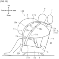
- FIG. 12 is a schematic diagram illustrating a state in which an airbag 3 of the occupant restraining device 100 according to Embodiment 3 is expanded and deployed.
- FIG. 12 illustrates expansion and deployment of only the airbag 3 on the left side of the occupant P.
- the airbag 3 expands and deploys on both the left and right sides of the occupant P in the same manner.
- FIG. 12 will be used to describe expansion and deployment of only the airbag 3 to the left of the occupant P as an example.
- the tensile cloth 2a and the tensile cloth 2c are provided for one airbag 3 on the left side.
- the upper end part 21a of the tensile cloth 2a and the upper end part 21c of the tensile cloth 2c are retained at a securing position F1 of the seatback 4 (see FIG. 1 ).
- a lower end part 22a of the tensile cloth 2a and a lower end part 22c of the tensile cloth 2c are retained by the lower securing part 81 at the front center section of the seat cushion 8 (see FIG. 1 ).
- the tensile cloths 2a and 2c are arranged together at the left side of the seat 5.
- the tensile cloth 2a has two joint sections 23a and 24a, and the joint section 23a is positioned below the joint section 24a.
- the tensile cloth 2c has two joint sections 23c and 24c, and the joint section 23c is located below the joint section 24c.
- the upper side of the tensile cloth 2a and the tensile cloth 2c are integrated together.
- the upper end part 21a of the tensile cloth 2a and the upper end part 21c of the tensile cloth 2c are sewn together over a prescribed range to form an integrated part 2e.
- the integrated part 2e is formed between the securing position F1 of the seatback 4 upper part and the joint section 24a of the tensile cloth 2a as well as the joint section 24c of the tensile cloth 2c.
- the integrated part 2e may be formed by using an adhesive.
- a retaining groove 9c is provided below the joint section 23a of the tensile cloth 2a and below the airbag 3 to receive and retain the tensile cloth 2a.
- a retaining groove 9d that receives and retains the tensile cloth 2c.
- the retaining grooves 9c and 9d constrain the airbag 3 to the tensile cloths 2a and 2c to prevent the airbag 3 from deviating from the assumed position thereof when the airbag 3 expands and deploys.
- the configuration of the retaining grooves 9c and 9d is the same as in Embodiment 2, so a detailed explanation is omitted.
- the airbag 3 is restrained by the tensile cloths 2a and 2c because the retaining grooves 9c and 9d are formed in the airbag 3 and the tensile cloths 2a and 2c are constrained to the retaining grooves 9c and 9d. Therefore, separation of the lower part of the airbag 3 from the tensile cloths 2a and 2c and deviation from the anticipated position can be suppressed. Therefore, the tensile cloth 2a and 2c can reliably bias arrangement of the airbag 3 to the side of the occupant P.
- the retaining grooves 9c and 9d are formed at positions where the tensile cloths 2a and 2c should contact the expanding and deploying airbag 3 to properly enable bias toward the occupant P. Therefore, when the airbag 3 is expanded and deployed, the tensile cloths 2a and 2c are easily received into the retaining grooves 9c and 9d.
- the upper end part 21a of the tensile cloth 2a and the upper end part 21c of the tensile cloth 2c have an integrated part 2e that is sewn over a prescribed range.
- the work of stowing the tensile cloth 2a and tensile cloth 2c in the side part of the seatback 4 is simplified. Also, when the airbag 3 expands and deploys, the upper end part 21a of the tensile cloth 2a and upper end part 21c of the tensile cloth 2c both pop out, allowing the airbag 3 to more rapidly adjust position.
- FIG. 13 is a schematic diagram illustrating a state in which an airbag 3 of the occupant restraining device 100 according to Embodiment 4 is expanded and deployed.
- FIG. 13 illustrates expansion and deployment of only the airbag 3 on the left side of the occupant P.
- the airbag 3 expands and deploys on both the left and right sides of the occupant P in the same manner.
- FIG. 13 will be used to describe expansion and deployment of only the airbag 3 to the left of the occupant P as an example.
- the tensile cloth 2a and the tensile cloth 2c are provided for one airbag 3 on the left side.
- the upper end part 21a of the tensile cloth 2a and the upper end part 21c of the tensile cloth 2c are secured to the upper part of the seatback 4.
- the lower end part 22a of the tensile cloth 2a and the lower end part 22c of the tensile cloth 2c are retained in the lower securing part 81 (see FIG. 1 ) of the seat cushion 8, via the pretensioner mechanisms 25a and 25b, respectively (tension applying mechanism).
- the pretensioner mechanisms 25a and 25b apply tension to the tensile cloths 2a and 2c.
- the pretensioner mechanism 25a is provided between the lower end part 22a of the tensile cloth 2a and the lower securing part 81 of the seat cushion 8, and the pretensioner mechanism 25b is provided between the lower end part 22c of the tensile cloth 2c and the lower securing part 81 of the seat cushion 8.
- the pretensioner mechanisms 25a and 25b are similar to buckle pretensioners used to retract the buckle of a vehicle seat belt in response to an impact.
- the pretensioner mechanisms 25a and 25b impart tension during expansion and deployment of the airbag 3 by pulling the tensile cloths 2a and 2c toward the lower securing part 81.
- the tensile cloth 2a has two joint sections 23a and 24a
- the tensile cloth 2c has two joint sections 23c and 24c, similar to Embodiment 2.
- the lower part of the airbag 3 has retaining grooves 9c and 9d that receive and hold the tensile cloths 2a and 2c, respectively, during expansion and deployment of the airbag 3.
- a retaining groove 9c is formed below the joint section 23a of the tensile cloth 2a to retain the tensile cloth 2a and a retaining groove 9d is formed below the joint section 23c of the tensile cloth 2c to retain the tensile cloth 2c.
- the occupant restraining device 100 of Embodiment 4 can prevent the lower part of the airbag 3 from separating from the tensile cloths 2a and 2c and deviating from the anticipated position, and the tensile cloths 2a and 2c can reliably bias the arrangement of the airbag 3 to the side of the occupant P.
- the pretensioner mechanisms 25a and 25b pull the tensile cloths 2a and 2c, respectively, toward the lower securing part 81 side during expansion and deployment of the airbag 3 enabling increasing the force with which the tensile cloths 2a and 2c bias the airbag 3 toward the side of the occupant P.
- the airbag 3 can be arranged more quickly and reliably on the side of the occupant P, and the occupant P can be protected.
- FIG. 14 is a schematic diagram illustrating a state in which an airbag 3 of the occupant restraining device 100 according to Embodiment 5 is expanded and deployed.
- FIG. 14 illustrates expansion and deployment of only the airbag 3 on the left side of the occupant P.
- the airbag 3 expands and deploys on both the left and right sides of the occupant P in the same manner.
- FIG. 14 will be used to describe expansion and deployment of only the airbag 3 to the left of the occupant P as an example.
- FIG. 14 for convenience, only the seat cushion 8 is illustrated in a longitudinal cross-sectional view.
- the tensile cloth 2a and the tensile cloth 2c are provided for one airbag 3 on the left side.
- the upper end part 21a of the tensile cloth 2a and the upper end part 21c of the tensile cloth 2c are secured to the upper part of the seatback 4.
- the lower end part 22a of the tensile cloth 2a and the lower end part 22c of the tensile cloth 2c are retained by the lower securing part 81 of the seat cushion 8 (see FIG. 1 ).
- the tensile cloth 2a has two joint sections 23a and 24a
- the tensile cloth 2c has two joint sections 23c and 24c, similar to Embodiment 2.
- the occupant restraining device 100 of Embodiment 5 also has retaining grooves 9c and 9d, which receive and retain the tensile cloths 2a and 2c, respectively, at the lower part of the airbag 3 during expansion and deployment of the airbag 3.
- a retaining groove 9c is formed below the joint section 23a of the tensile cloth 2a
- a retaining groove 9d is formed below the joint section 23c of the tensile cloth 2c.
- the configuration of the retaining grooves 9c and 9d is the same as in Embodiment 2, so a detailed explanation is omitted.
- the seat cushion 8 includes a cushion pad 82 and a panel member 86 arranged on the lower side of the cushion pad 82 and supporting the cushion pad 82.
- the cushion pad 82 includes a shock absorbing material that absorbs impact, and the panel member 86 constitutes the bottom section of the seat cushion 8.
- the seat cushion 8 includes an airbag device 83 (tension applying mechanism) therein.
- the airbag device 83 is interposed between the cushion pad 82 and panel member 86. Additionally, the airbag device 83 includes an airbag 85, which is, for example, a bag body formed by sewing the peripheral edge of two panels, and an inflator 84 that emits gas into the airbag 85.
- the airbag 85 Before expansion and deployment, the airbag 85 is laid flat on the panel member 86 at a position corresponding to the thigh to buttocks of the occupant P.
- the inflator 84 operates to supply gas into the airbag 85, which expands and deploys upward.
- the lower part of the airbag 3 can be prevented from separating from the tensile cloth 2a and 2c and deviating from the assumed position, and the tensile cloths 2a and 2c can reliably bias arrangement of the airbag 3 to the side of the occupant P.
- the airbag device 83 is provided inside the seat cushion 8, and when a vehicle collision occurs, the airbag 85 expands and deploys from the panel member 86 toward the cushion pad 82. At this time, the airbag 85 pushes up from the thigh of the occupant P to the upper side via the cushion pad 82. This increases the load on the tensile cloth 2a and tensile cloth 2c, and tension is applied to the tensile cloth 2a and tensile cloth 2c.
- the airbag 3 can be arranged on the side of the occupant P to receive and protect the occupant P.
Landscapes
- Engineering & Computer Science (AREA)
- Mechanical Engineering (AREA)
- Air Bags (AREA)
Abstract
Description
- The present invention relates to an occupant restraining device provided with an airbag.
This application claims priority based onJapanese Application 2020-127516 filed July 28, 2020 - Airbag devices have become widely used in recent years. An airbag device is a restraining device that operates in the case of an emergency such as a vehicle collision and, for example, the airbag is expanded and deployed by gas pressure to protect the occupant. There are various types of airbag devices depending on the installation site and application.
-
Patent Document 1 discloses side airbag devices that are provided on both sides of a vehicle seat and expand and deploy to the sides of the occupant. - [Patent Document 1]
Japanese Unexamined Patent Application 2014-034356 - On the other hand, in order for the airbag to expand and deploy in order to receive the occupant, the airbag needs to be positioned at an expected position.
Therefore, a technique for adjusting the position of an expanding and deploying airbag using a tensile cloth is also known. With this manner of technique, when the airbag expands and deploys, the tensile cloth surrounds and retains the outside of the airbag and biases the airbag to the side of the occupant. - On the other hand, if the tensile cloth biases the expanding and deploying airbag toward the occupant, the tensile cloth may not be able to properly adjust the airbag position if the airbag is diverted from the intended position thereof.
However, the technique according toPatent Document 1 as described above cannot solve such a problem. - In light of the circumstances described above, an object of the present invention is to provide an occupant restraining device in which the tensile cloth can more accurately adjust the position of the airbag when the airbag is expanded and deployed.
- The occupant restraining device according to the present invention includes:
- tensile cloths having both ends secured to the upper and lower parts of a vehicle seat respectively, and that bias an expanding and deploying airbag to the side of an occupant seated in the seat, towards the occupant, wherein
- the airbag is formed with retaining grooves that retain the tensile cloths during expansion and deployment.
- According to the present invention, when the airbag expands and deploys, the airbag can be more accurately positioned.
-
-
FIG. 1 is a diagram illustrating a state in which the occupant restraining device according toEmbodiment 1 is attached to a vehicle seat. -
FIG. 2 is a schematic diagram illustrating a state in which an airbag of the occupant restraining device is expanded and deployed. -
FIG. 3 is an enlarged view of the expanded and deployed airbag. -
FIG. 4 is a transverse cross-sectional view of the airbag along line IV-IV inFIG. 3 . -
FIG. 5 is a longitudinal cross-sectional view of the airbag along line V-V inFIG. 3 . -
FIG. 6 is a longitudinal cross-sectional view of the airbag along line VI-VI inFIG. 5 . -
FIG. 7 is a schematic diagram illustrating a state in which an airbag of the occupant restraining device according to Embodiment 2 is expanded and deployed. -
FIG. 8 is an enlarged view of the expanded and deployed airbag. -
FIG. 9 is a transverse cross-sectional view of the airbag along line I X- I X inFIG. 8 . -
FIG. 10 is a longitudinal cross-sectional view of the airbag along line X-X inFIG. 8 . -
FIG. 11 is a longitudinal cross-sectional view of the airbag along line X I - X I inFIG. 10 . -
FIG. 12 is a schematic diagram illustrating a state in which an airbag of the occupant restraining device according to Embodiment 3 is expanded and deployed. -
FIG. 13 is a schematic diagram illustrating a state in which an airbag of the occupant restraining device according to Embodiment 4 is expanded and deployed. -
FIG. 14 is a schematic diagram illustrating a state in which an airbag of the occupant restraining device according to Embodiment 5 is expanded and deployed. - The occupant restraining device according to the Embodiment of the present invention will be described in detail below according to the diagrams. The occupant restraining device according to the embodiment of the present invention is equipped to a seat of a vehicle.
-
FIG. 1 is a diagram illustrating a state in which theoccupant restraining device 100 according toEmbodiment 1 is attached to avehicle seat 5.FIG. 1 illustrates a state before the airbag expands and deploys. For convenience, descriptions will be given in the following using each of the front-to-back, left-right, and up-down directions defined in the figures. - The
seat 5 includes theseat cushion 8 on which the occupant sits, and aseatback 4 that stands up from the back side of theseat cushion 8 and supports the back of the occupant. The lower edge of theseatback 4 is provided at the rear edge of theseat cushion 8, and is rotatably retained by ashaft 6. Accordingly, theseatback 4 can be adjusted at an angle by rotating theshaft 6 in the front-to-back direction. - A
headrest part 7 is provided in the center in the left-right direction on the upper part of theseatback 4 rising up from theseatback 4. Theheadrest part 7 supports the head of the occupant seated on theseat cushion 8. - The
occupant restraining device 100 includes airbag modules 1a and 1b containing an airbag stowed within the housing andtensile cloths 2a and 2b that perform position adjustment of the airbag that expands and deploys. The airbag module 1a is provided on the left side of theseatback 4, and the airbag module 1b is provided on the right side of theseatback 4. The airbag modules 1a and 1b are arranged between the frame (not shown) inside theseatback 4 and the cover covering the frame. -
FIG. 1 illustrates a case where an airbag module 1b is provided on the right side of theseatback 4 and an airbag module 1a is provided on the left side of theseatback 4, but the present invention is not limited to this and the airbag modules 1a and 1b may be provided on only one side. - Each of the airbag modules 1a and 1b includes an airbag 3 (see
FIG. 2 ), and an inflator (not shown) that emits gas into theairbag 3. - The
airbag 3 is formed by sewing the outer edges of two panels together, with, for example, the aforementioned inflator arranged inside theairbag 3. In the event of a vehicle collision, theoccupant restraining device 100 protects the occupants through expansion and deployment of theairbag 3 in the forward direction and receiving the occupant. - In
FIG. 1 , for convenience, thetensile cloths 2a and 2b are illustrated by an alternate long and short dashed line.Tensile cloths 2a and 2b are strips of prescribed width, with thetensile cloth 2a being provided on the left side of theseatback 4 and the tensile cloth 2b being provided on the right side of theseatback 4. - With the
tensile cloth 2a, theupper end part 21a is secured to a securing position F1 of theseatback 4 frame on the left side of theheadrest part 7 that is theupper surface 41 of theseatback 4. With the tensile cloth 2b, theupper end part 21b is secured to a securing position F2 of theseatback 4 frame on the right side of theheadrest part 7 that is theupper surface 41 of theseatback 4. - On the other hand, a
lower end part 22a of thetensile cloth 2a and alower end part 22b of the tensile cloth 2b are retained by the lower securingpart 81 provided in the center at the front of theseat cushion 8. Thelower securing part 81 includes, for example, two metal plates, and thelower end parts tensile cloths 2a and 2b are sandwiched between such metal plates. - The
tensile cloths 2a and 2b are arranged inside these side parts from theseatback 4 to theseat cushion 8. Thetensile cloth 2a is arranged from the left side of theseatback 4 to the left side of theseat cushion 8, and the tensile cloth 2b is arranged from the right side of theseatback 4 to the right side of theseat cushion 8. - Each of the
tensile cloths 2a and 2b has the middle section thereof passing through the airbag modules 1a and 1b, and are joined to eachairbag 3 in the airbag modules 1a and 1b as described below. - With the
occupant restraining device 100 according toEmbodiment 1, when a vehicle collides or is heavily impacted, theairbag 3 instantly breaks the cover of theseatback 4 and expands and deploys toward the front of theseat 5. In addition, at the same time as the expansion and deployment of theairbag 3, thetensile cloths 2a and 2b burst out from both side parts of theseat 5 together with theairbag 3 to retain the expanding and deployingairbag 3, enabling arranging theairbag 3 at the center of theseatback 4, in other words, the occupant side of theseat cushion 8. -
FIG. 2 is a schematic diagram illustrating a state in which anairbag 3 of theoccupant restraining device 100 is expanded and deployed. For convenience,FIG. 2 illustrates only the expansion and deployment of theairbag 3 on the left side of the occupant P seated on theseat cushion 8. In effect, however, theairbag 3 expands and deploys similarly on both the left and right sides of the occupant P, where position adjustment of theairbag 3 on the left side is performed by thetensile cloth 2a, and position adjustment of theairbag 3 on the right side is performed by the tensile cloth 2b (seeFIG. 3 ). Therefore, a description of the action and movement of thetensile cloth 2a on the left side of theseat 5 will be described usingFIG. 2 , and the description of the tensile cloth 2b will be omitted. - As illustrated in
FIG. 2 , when a vehicle is in a collision, theairbag 3 on the left side breaks the cover from the inside of theside surface 42 of theseatback 4 and expands and deploys toward the front of theseat 5. In addition, simultaneous with the expansion and deployment of theairbag 3, thetensile cloth 2a also bursts out and surrounds the outside of the expanding and deployingairbag 3, which is then arranged to the center of theseatback 4, in other words, where the occupant P is sitting on theseat cushion 8, and holds and restrains the occupant P to protect the occupant P. - Here, the
tensile cloth 2a inevitably comes into partial contact with the outer surface of theairbag 3. With theoccupant restraining device 100 according toEmbodiment 1, a prescribed location of the contact area between theairbag 3 and thetensile cloth 2a is sewn together to join thetensile cloth 2a to theairbag 3. - In the example of
FIG. 2 , thetensile cloth 2a is sewn to theairbag 3 at twojoint sections joint section 23a is positioned below thejoint section 24a. - In addition, in the
occupant restraining device 100, a retaining groove 9a that retains thetensile cloth 2a is provided below thejoint section 23a and on the lower part of theairbag 3. The retaining groove 9a receives and retains thetensile cloth 2a when theairbag 3 expands and deploys, preventing theairbag 3 from leaving the normal position thereof. - Here, the lower part of the
airbag 3 means from the lower end part of the expanded and deployedairbag 3 to the part of theairbag 3 that is most inflated in the vehicle width direction. The section of theairbag 3 lower than the center in the vertical direction is illustrated in general, but is not limited thereto. - In addition the upper part of the
airbag 3 is defined as from the upper end part of the expanded and deployedairbag 3 to the part of theairbag 3 that is most inflated in the vehicle width direction. The section of theairbag 3 higher than the center in the vertical direction is illustrated in general, but is not limited thereto. - Note that the most inflated part of the
airbag 3 in the vehicle width direction is the most inflated part in the contact area where the expanded and deployedairbag 3 contacts thetensile cloths 2a and 2b, and may differ from the most inflated part of theentire airbag 3. -
FIG. 3 is an enlarged view of the expanded and deployedairbag 3.FIG. 4 is a cross-sectional view of theairbag 3 along the line IV-IV inFIG. 3 .FIG. 5 is a cross-sectional view of theairbag 3 along the line V-V inFIG. 3 .FIG. 4 is a view from below. InFIG. 5 , the occupant P is illustrated as a double-dashed line for convenience of explanation. InFIG. 3 andFIG. 4 , thetensile cloth 2a is illustrated as a double-dashed line for convenience. -
FIG. 6 is a cross-sectional view of theairbag 3 along line VI-VI inFIG. 5 . InFIG. 6 , for convenience, thetensile cloth 2a is illustrated by a dashed line. - The
airbag 3 is a bag body formed by joining a first panel 3a (contact section) and asecond panel 3b (non-contact section) of the same approximate shape by sewing the perimeters together. The first panel 3a andsecond panel 3b are, for example, circular. Therefore, theairbag 3 is restricted by aseam 34 during expansion and deployment, and when the expansion and deployment is complete, theairbag 3 has a substantially elliptic shape in the longitudinal and transverse sections. - When the
airbag 3 is expanded and deployed, the first panel 3a and thesecond panel 3b face each other, with the first panel 3a joined to thetensile cloth 2a as described above and thesecond panel 3b facing the occupant P. InFIG. 4 andFIG. 5 , theseam 34 of theairbag 3 is illustrated by an alternate long and short dashed line. - The
airbag 3 is also equipped with aninternal tether 32 that controls the shape of theairbag 3 during expansion and deployment. Furthermore, the lower part of theairbag 3 has a retaining groove 9a in the first panel 3a and a groove 9b in thesecond panel 3b, as described below. The retaining groove 9a and groove 9b are formed by theinternal tether 32. For the sake of explanation, the case in which theairbag 3 is expanded and deployed will be used below. - As mentioned above, the
internal tether 32 is provided inside theairbag 3. Theinternal tether 32 has a substantially trapezoidal sheet shape, with the shorter of the two substantially parallel sides on the lower side and the longer side on the upper side, and is located at the lower part of the airbag 3 (seeFIG. 5 ). Theinternal tether 32 is provided at a prescribed distance from the bottom edge of theairbag 3. - The
internal tether 32 is constructed between the first panel 3a and thesecond panel 3b. One of the two sides adjacent to the aforementioned short side of theinternal tether 32 is sewn to the bottom of the first panel 3a and the other is sewn to the bottom of thesecond panel 3b. This forms aseam 35a in the first panel 3a and aseam 35b in thesecond panel 3b (seeFIG. 3 andFIG. 4 ). - As described above, the inside of the first panel 3a and
second panel 3b are restrained by theinternal tether 32, so that theairbag 3 is restricted from expanding in the direction opposite the first panel 3a andsecond panel 3b (hereafter, the thickness direction of the airbag 3) during expansion and deployment. - In particular, the first panel 3a is joined to the
internal tether 32 at thelower seam 35a and thesecond panel 3b is joined to theinternal tether 32 at thelower seam 35b. Thus, in the first panel 3a, other sections can expand relatively freely except for the section corresponding toseam 35a, and in thesecond panel 3b, other sections can expand relatively freely except for the section corresponding toseam 35b. - That is, when the
airbag 3 is expanded and deployed, the lower part of the first panel 3a and the lower part of thesecond panel 3b pull against each other via theinternal tether 32, so that in the first panel 3a, the area pertaining toseam 35a and the area aroundseam 35a, and in thesecond panel 3b, the area pertaining toseam 35b and the area aroundseam 35b, are concave. This forms a retaining groove 9a in the first panel 3a and a groove 9b in thesecond panel 3b. - In other words, in the first panel 3a, a retaining groove 9a is formed in the section corresponding to the internal tether 32 (
seam 35a). In thesecond panel 3b as well, a groove 9b is formed in the area corresponding to the internal tether 32 (seam 35b) (seeFIG. 4 ). InFIG. 5 , the outside of the area enclosed by the dashed line corresponds to retaining groove 9a and groove 9b. - As mentioned above, the
internal tether 32 is a substantially trapezoidal shape and has a prescribed dimension in the height direction. Therefore, seams 35a and 35b are formed in the vertical direction and over a prescribed range. Thus, the retaining groove 9a and groove 9b extend in the vertical direction and over a prescribed range. Furthermore, since theinternal tether 32 has a substantially trapezoidal shape, the dimensions thereof in the direction that intersects said height direction (hereinafter referred to as the width direction) gradually decrease in the downward direction. - Furthermore, as described above, the periphery of the
seam 35a in the first panel 3a and the periphery of theseam 35b in thesecond panel 3b are recessed, and the dimension of theinternal tether 32 in the width direction gradually decreases in the downward direction. As a result, at the bottom of theairbag 3, the retaining groove 9a of the first panel 3a, and the groove 9b of thesecond panel 3b are connected, forming a recessedsection 36 at the bottom end of theairbag 3. - As described above, in the
occupant restraining device 100 ofEmbodiment 1, a retaining groove 9a is formed in the lower part of the first panel 3a that contacts thetensile cloth 2a during expansion and deployment of theairbag 3, extending in the vertical direction. During expansion and deployment of theairbag 3, thetensile cloth 2a is received in the retaining groove 9a (seeFIG. 4 ). With thetensile cloth 2a, both edges in the width direction are in contact with the first panel 3a in the retaining groove 9a, whereas excluding the edges, there is a gap between the center thereof and the first panel 3a. - Thus, the
tensile cloth 2a can slide along the length of the retaining groove 9a on the first panel 3a within the retaining groove 9a (seeFIG. 6 ). Thetensile cloth 2a is restricted from moving in the width direction of the retaining groove 9a.
Therefore, during expansion and deployment, the lower part of theairbag 3 can be prevented from separating from thetensile cloth 2a and deviating from the anticipated position, and thetensile cloth 2a can reliably apply bias to theairbag 3 and adjust the position thereof toward the occupant P. - The location of the
internal tether 32 is not limited to the positions illustrated inFIG. 4 to FIG. 6 . Theinternal tether 32 is provided such that the retaining groove 9a is formed at a position causing thetensile cloth 2a to suitably bias the expanding and deployingairbag 3 toward the occupant P. - As mentioned above, the
internal tether 32 has a substantially trapezoidal shape, and the dimension thereof in the width direction gradually decreases in the downward direction. On the other hand, thelower end part 22a of thetensile cloth 2a is retained in the lower securingpart 81 on the center side of the front of the seat cushion 8 (seeFIG. 1 ).
That is, the closer the retaining groove 9a is to the lower end of theairbag 3, the closer it is to thelower end part 22a of thetensile cloth 2a (lower securing part 81). Therefore, thetensile cloth 2a is easily received in the retaining groove 9a during the expansion and deployment of theairbag 3. - Furthermore, since the retaining groove 9a is provided at the lower part of the
airbag 3 and a recessedsection 36 is formed in the lower end part of theairbag 3, when theairbag 3 expands and deploys, thetensile cloth 2a is caught in the retaining groove 9a and recessedsection 36 to lift and position theairbag 3 more precisely to the desired position closer to the head of the occupant P. - As described above, by joining the
airbag 3 and thetensile cloth 2a at thejoint sections airbag 3 can be more stably adjusted. - In the above, the case in which
tensile cloth 2a has twojoint sections joint sections - In the above, the case in which the
tensile cloth 2a has twojoint sections tensile cloth 2a, such a joint section may be at one location or at three or more locations. - In the above description, the case in which two
joint sections tensile cloth 2a has been described as an example, but is not limited thereto. For example, each of thejoint sections tensile cloth 2a. - In the above, the case in which the
tensile cloths 2a and 2b are sewn to theairbag 3 has been described as an example, but is not limited thereto. For example, thetensile cloth 2a may be fixed to theairbag 3 by an adhesive, or may be fixed using a surface fastener or the like. - Note that the case in which the
tensile cloths 2a and 2b have a band shape has been described as an example, but they are not limited thereto. Thetensile cloths 2a and 2b may be a wide cloth or a large area of cloth. - In
Embodiment 1, a case where one of thetensile cloths 2a and 2b is provided for eachairbag 3 has been described as an example, but is not limited thereto. -
FIG. 7 is a schematic diagram illustrating a state in which anairbag 3 of theoccupant restraining device 100 according toEmbodiment 2 is expanded and deployed. InFIG. 7 , for convenience, expansion and deployment of only theairbag 3 on the left side of the occupant P is illustrated, however in actuality, theairbag 3 expands and deploys in the same manner on both the left and right sides of the occupant P. - In the
occupant restraining device 100 according toEmbodiment 2, position adjustment is performed by thetensile cloths left side airbag 3, and position adjustment is performed by the tensile cloths 2b and 2d on the right side airbag 3 (seeFIG. 8 ).
In the following, an example of expansion and deployment of only theairbag 3 on the left side of the occupant P will be described with reference toFIG. 7 . - The
upper end part 21a of thetensile cloth 2a and theupper end part 21c of thetensile cloth 2c are secured to the upper part of theseatback 4. In addition, alower end part 22a of thetensile cloth 2a and alower end part 22c of thetensile cloth 2c are retained by the lower securingpart 81 at the front center section of the seat cushion 8 (seeFIG. 1 ). Thetensile cloths seat 5. - With the
occupant restraining device 100 according toEmbodiment 2, thetensile cloth 2a has twojoint sections tensile cloth 2c has twojoint sections 23c and 24c. Of thejoint section 23a andjoint section 24a, thejoint section 23a is positioned lower than thejoint section 24a and of thejoint section 23c and the joint section 24c, thejoint section 23c is positioned lower than the joint section 24c. - With the
occupant restraining device 100, a retaininggroove 9c is provided below thejoint section 23a of thetensile cloth 2a and below the lower part of theairbag 3 to receive and retain thetensile cloth 2a during expansion and deployment of theairbag 3. The retaining groove 9d is provided below thejoint section 23c of thetensile cloth 2c and below the lower part of theairbag 3 to receive and retain thetensile cloth 2c during expansion and deployment of theairbag 3. The retaininggrooves 9c and 9d receive and retain thetensile cloths airbag 3 expands and deploys, preventing theairbag 3 from deviating from the anticipated position thereof. -
FIG. 8 is an enlarged view of the expanded and deployedairbag 3.FIG. 9 is a cross-sectional view of theairbag 3 along line IX-IX inFIG. 8 .FIG. 10 is a longitudinal cross-sectional view of theairbag 3 along line X-X inFIG. 8 .FIG. 9 is a view from below. InFIG. 10 , the occupant P is illustrated as a double-dashed line for convenience of explanation.FIG. 11 is a longitudinal cross-sectional view of theairbag 3 along line XI-XI inFIG. 10 . For convenience, thetensile cloths FIG. 8 andFIG. 9 and as dashed lines inFIG. 11 . -
Airbag 3 is a bag body formed by joining a first panel 3a and asecond panel 3b of the same shape by sewing the perimeters together. The first panel 3a andsecond panel 3b are, for example, circular. Therefore, theairbag 3 is restricted by aseam 34 during expansion and deployment, and when the expansion and deployment is complete, theairbag 3 has a substantially elliptic shape in the longitudinal and transverse sections. - When the
airbag 3 is expanded and deployed, the first panel 3a and thesecond panel 3b face each other, with the first panel 3a joined to thetensile cloths second panel 3b facing the occupant P. InFIG. 9 andFIG. 10 , theseam 34 of theairbag 3 is illustrated by an alternate long and short dashed line. - In addition, the
airbag 3 hasinternal tethers airbag 3 has retaininggrooves 9c and 9d in the first panel 3a and grooves 9e and 9f in thesecond panel 3b, as described below. Retaininggrooves 9c and 9d and grooves 9e and 9f are formed by theinternal tethers
For the sake of explanation, the case in which theairbag 3 is expanded and deployed will be used below. - As described above, the
internal tethers airbag 3. Theinternal tethers FIG. 10 ). Theinternal tethers airbag 3. Theinternal tethers - The
internal tethers second panel 3b. One of the two sides adjacent to the aforementioned short side of theinternal tethers second panel 3b.Seams seams 35e and 35f are formed in thesecond panel 3b (seeFIG. 8 andFIG. 9 ). - As mentioned above, the inner sides of the first panel 3a and
second panel 3b are restrained by theinternal tethers airbag 3 is restricted from expanding in the thickness direction during expansion and deployment. - In particular, the first panel 3a is joined to the
internal tethers lower seams second panel 3b is joined to theinternal tethers lower seams 35e and 35f. Thus, in the first panel 3a, other sections can expand relatively freely except for the sections corresponding toseams second panel 3b, other sections can expand relatively freely except for the sections corresponding toseams 35e and 35f. - That is, during expansion and deployment of the
airbag 3, the lower part of the first panel 3a and the lower part of thesecond panel 3b pull against each other via theinternal tethers seams seams second panel 3b, the area pertaining to theseams 35e and 35f and the area around theseams 35e and 35f are concave. This creates retaininggrooves 9c and 9d in the first panel 3a and grooves 9e and 9f in thesecond panel 3b. - In other words, in the first panel 3a, the retaining
grooves 9c and 9d are formed in the sections corresponding to theinternal tethers seams second panel 3b, grooves 9e and 9f are also formed in the section corresponding to theinternal tethers seams 35e and 35f) (seeFIG. 9 ). InFIG. 10 , the outside of the regions A and C surrounded by dashed lines correspond to the retaininggrooves 9c and 9d, respectively, and the outside of the regions B and D surrounded by dashed lines correspond to the grooves 9e and 9f, respectively. - As described above, each of the
internal tethers seams grooves 9c, 9d and 9e, 9f extend in the vertical direction and over a prescribed range. Furthermore, since theinternal tethers - Furthermore, as described above, the areas around the
seams seams 35e and 35f in thesecond panel 3b are concave, and the dimensions of theinternal tethers airbag 3, the retaininggrooves 9c and 9d of the first panel 3a and grooves 9e and 9f of thesecond panel 3b are connected, and two recessedsections 36a and 36b are formed at the lower end part of theairbag 3. - As described above, in the
occupant restraining device 100 ofEmbodiment 2, retaininggrooves 9c and 9d are formed in the first panel 3a extending in the vertical direction during expansion and deployment of theairbag 3. During expansion and deployment of theairbag 3, thetensile cloths grooves 9c and 9d (seeFIG. 9 ). With thetensile cloth 2a, both edges in the width direction are in contact with the first panel 3a in the retaininggroove 9c, whereas excluding the edges, there is a gap between the center thereof and the first panel 3a. In addition, with thetensile cloth 2c, both edges in the width direction are in contact with the first panel 3a in the retaining groove 9d, whereas excluding the edges, there is a gap between the center thereof and the first panel 3a (seeFIG. 9 ). - Thus, the
tensile cloth 2a can slide in the retaininggroove 9c along the length of the retaininggroove 9c on the first panel 3a, and thetensile cloth 2c can slide in the retaining groove 9d along the length of the retaining groove 9d on the first panel 3a (seeFIG. 11 ).
In addition, thetensile cloth 2a is restricted from moving in the width direction of the retaininggroove 9c, and thetensile cloth 2c is restricted from moving in the width direction of the retaining groove 9d. - Therefore, during expansion and deployment, the lower part of the
airbag 3 can be prevented from separating from thetensile cloths tensile cloths airbag 3 and adjust the position thereof toward the occupant P. - The
internal tethers grooves 9c and 9d are formed at positions where thetensile cloths airbag 3 toward the occupant P. - As described above, the
internal tethers grooves 9c and 9d are to the lower end part of theairbag 3, the closer they are to thelower end part 22a of thetensile cloth 2a and thelower end part 22c of thetensile cloth 2c, that is, the lower securingpart 81. Therefore, thetensile cloths grooves 9c and 9d during the expansion and deployment of theairbag 3. - Furthermore, since retaining
grooves 9c and 9d are provided at the lower part of theairbag 3 and recessedsections 36a and 36b are formed at the lower end part of theairbag 3, when theairbag 3 expands and deploys, thetensile cloth 2a enters into the retaininggroove 9c and recessed section 36a andtensile cloth 2c enters into the retaining groove 9d and recessedsection 36b to lift and more properly position theairbag 3 in the desired position closer to the head of the occupant P. - As described above, the
airbag 3 andtensile cloth 2a are pre-joined atjoint sections airbag 3 andtensile cloth 2c are pre-joined atjoint sections 23c and 24c to enable more stable adjustment of the position of the expanding and deployingairbag 3. - As described above, as two
tensile cloths airbag 3, and theairbags 3 and the twotensile cloths joint sections airbag 3 can be more stably adjusted. - In what has been described above, the case where two
tensile cloths airbag 3 has been described as an example, but is not limited thereto, and there may be three or moretensile cloths 2 for oneairbag 3. - Sections similar to
Embodiment 1 are given the same code and detailed description thereof is omitted. -
FIG. 12 is a schematic diagram illustrating a state in which anairbag 3 of theoccupant restraining device 100 according toEmbodiment 3 is expanded and deployed.FIG. 12 illustrates expansion and deployment of only theairbag 3 on the left side of the occupant P. In actuality, theairbag 3 expands and deploys on both the left and right sides of the occupant P in the same manner. However, in the following,FIG. 12 will be used to describe expansion and deployment of only theairbag 3 to the left of the occupant P as an example. - With the
occupant restraining device 100 according toEmbodiment 3, thetensile cloth 2a and thetensile cloth 2c are provided for oneairbag 3 on the left side. Theupper end part 21a of thetensile cloth 2a and theupper end part 21c of thetensile cloth 2c are retained at a securing position F1 of the seatback 4 (seeFIG. 1 ). - In addition, a
lower end part 22a of thetensile cloth 2a and alower end part 22c of thetensile cloth 2c are retained by the lower securingpart 81 at the front center section of the seat cushion 8 (seeFIG. 1 ). Thetensile cloths seat 5. - The
tensile cloth 2a has twojoint sections joint section 23a is positioned below thejoint section 24a. In addition, thetensile cloth 2c has twojoint sections 23c and 24c, and thejoint section 23c is located below the joint section 24c. - With the
occupant restraining device 100 according toEmbodiment 3, the upper side of thetensile cloth 2a and thetensile cloth 2c are integrated together. In other words, theupper end part 21a of thetensile cloth 2a and theupper end part 21c of thetensile cloth 2c are sewn together over a prescribed range to form an integrated part 2e. The integrated part 2e is formed between the securing position F1 of theseatback 4 upper part and thejoint section 24a of thetensile cloth 2a as well as the joint section 24c of thetensile cloth 2c. In addition, the integrated part 2e may be formed by using an adhesive. - In the
occupant restraining device 100, as inEmbodiment 2, a retaininggroove 9c is provided below thejoint section 23a of thetensile cloth 2a and below theairbag 3 to receive and retain thetensile cloth 2a. Below thejoint section 23c of thetensile cloth 2c and below the lower part of theairbag 3, there is a retaining groove 9d that receives and retains thetensile cloth 2c. The retaininggrooves 9c and 9d constrain theairbag 3 to thetensile cloths airbag 3 from deviating from the assumed position thereof when theairbag 3 expands and deploys. - The configuration of the retaining
grooves 9c and 9d is the same as inEmbodiment 2, so a detailed explanation is omitted. - As described above, in the
occupant restraining device 100 ofEmbodiment 3, during expansion and deployment, theairbag 3 is restrained by thetensile cloths grooves 9c and 9d are formed in theairbag 3 and thetensile cloths grooves 9c and 9d. Therefore, separation of the lower part of theairbag 3 from thetensile cloths tensile cloth airbag 3 to the side of the occupant P. - The retaining
grooves 9c and 9d are formed at positions where thetensile cloths airbag 3 to properly enable bias toward the occupant P. Therefore, when theairbag 3 is expanded and deployed, thetensile cloths grooves 9c and 9d. - Furthermore, with the
occupant restraining device 100 according toEmbodiment 3, as described above, theupper end part 21a of thetensile cloth 2a and theupper end part 21c of thetensile cloth 2c have an integrated part 2e that is sewn over a prescribed range. - Therefore, the work of stowing the
tensile cloth 2a andtensile cloth 2c in the side part of theseatback 4 is simplified. Also, when theairbag 3 expands and deploys, theupper end part 21a of thetensile cloth 2a andupper end part 21c of thetensile cloth 2c both pop out, allowing theairbag 3 to more rapidly adjust position. - Note that, while in the description, only the
upper end part 21a of thetensile cloth 2a and theupper end part 21c of thetensile cloth 2c are integrated, this is not a limitation. Thelower end part 22a of thetensile cloth 2a and thelower end part 22c of thetensile cloth 2c may be integrated together. - Sections similar to
Embodiment 1 are given the same code and detailed description thereof is omitted. -
FIG. 13 is a schematic diagram illustrating a state in which anairbag 3 of theoccupant restraining device 100 according toEmbodiment 4 is expanded and deployed. For convenience,FIG. 13 illustrates expansion and deployment of only theairbag 3 on the left side of the occupant P. In actuality, theairbag 3 expands and deploys on both the left and right sides of the occupant P in the same manner. However, in the following,FIG. 13 will be used to describe expansion and deployment of only theairbag 3 to the left of the occupant P as an example. - With the
occupant restraining device 100 according toEmbodiment 4, thetensile cloth 2a and thetensile cloth 2c are provided for oneairbag 3 on the left side. Theupper end part 21a of thetensile cloth 2a and theupper end part 21c of thetensile cloth 2c are secured to the upper part of theseatback 4. - On the other hand, the
lower end part 22a of thetensile cloth 2a and thelower end part 22c of thetensile cloth 2c are retained in the lower securing part 81 (seeFIG. 1 ) of theseat cushion 8, via thepretensioner mechanisms 25a and 25b, respectively (tension applying mechanism). Thepretensioner mechanisms 25a and 25b apply tension to thetensile cloths - The pretensioner mechanism 25a is provided between the
lower end part 22a of thetensile cloth 2a and the lower securingpart 81 of theseat cushion 8, and thepretensioner mechanism 25b is provided between thelower end part 22c of thetensile cloth 2c and the lower securingpart 81 of theseat cushion 8. - The
pretensioner mechanisms 25a and 25b are similar to buckle pretensioners used to retract the buckle of a vehicle seat belt in response to an impact. Thepretensioner mechanisms 25a and 25b impart tension during expansion and deployment of theairbag 3 by pulling thetensile cloths part 81. - With the
occupant restraining device 100 according toEmbodiment 4, thetensile cloth 2a has twojoint sections tensile cloth 2c has twojoint sections 23c and 24c, similar toEmbodiment 2.
In addition, as inEmbodiment 2, in theoccupant restraining device 100 ofEmbodiment 4, the lower part of theairbag 3 has retaininggrooves 9c and 9d that receive and hold thetensile cloths airbag 3. A retaininggroove 9c is formed below thejoint section 23a of thetensile cloth 2a to retain thetensile cloth 2a and a retaining groove 9d is formed below thejoint section 23c of thetensile cloth 2c to retain thetensile cloth 2c. - With the above configuration, the
occupant restraining device 100 ofEmbodiment 4 can prevent the lower part of theairbag 3 from separating from thetensile cloths tensile cloths airbag 3 to the side of the occupant P. - In addition, with the
occupant restraining device 100 according toEmbodiment 4, thepretensioner mechanisms 25a and 25b pull thetensile cloths part 81 side during expansion and deployment of theairbag 3 enabling increasing the force with which thetensile cloths airbag 3 toward the side of the occupant P. Thus, theairbag 3 can be arranged more quickly and reliably on the side of the occupant P, and the occupant P can be protected. - Sections similar to
Embodiment 1 are given the same code and detailed description thereof is omitted. -
FIG. 14 is a schematic diagram illustrating a state in which anairbag 3 of theoccupant restraining device 100 according toEmbodiment 5 is expanded and deployed. For convenience,FIG. 14 illustrates expansion and deployment of only theairbag 3 on the left side of the occupant P. In actuality, theairbag 3 expands and deploys on both the left and right sides of the occupant P in the same manner. However, in the following,FIG. 14 will be used to describe expansion and deployment of only theairbag 3 to the left of the occupant P as an example. - Note that in
FIG. 14 , for convenience, only theseat cushion 8 is illustrated in a longitudinal cross-sectional view. - With the
occupant restraining device 100 according toEmbodiment 5, thetensile cloth 2a and thetensile cloth 2c are provided for oneairbag 3 on the left side. Theupper end part 21a of thetensile cloth 2a and theupper end part 21c of thetensile cloth 2c are secured to the upper part of theseatback 4. In addition, thelower end part 22a of thetensile cloth 2a and thelower end part 22c of thetensile cloth 2c are retained by the lower securingpart 81 of the seat cushion 8 (seeFIG. 1 ). - With the
occupant restraining device 100 according toEmbodiment 5, thetensile cloth 2a has twojoint sections tensile cloth 2c has twojoint sections 23c and 24c, similar toEmbodiment 2.
As inEmbodiment 2, theoccupant restraining device 100 ofEmbodiment 5 also has retaininggrooves 9c and 9d, which receive and retain thetensile cloths airbag 3 during expansion and deployment of theairbag 3. A retaininggroove 9c is formed below thejoint section 23a of thetensile cloth 2a, and a retaining groove 9d is formed below thejoint section 23c of thetensile cloth 2c.
The configuration of the retaininggrooves 9c and 9d is the same as inEmbodiment 2, so a detailed explanation is omitted. - On the other hand, the
seat cushion 8 includes acushion pad 82 and apanel member 86 arranged on the lower side of thecushion pad 82 and supporting thecushion pad 82. Thecushion pad 82 includes a shock absorbing material that absorbs impact, and thepanel member 86 constitutes the bottom section of theseat cushion 8. - The
seat cushion 8 includes an airbag device 83 (tension applying mechanism) therein. Theairbag device 83 is interposed between thecushion pad 82 andpanel member 86. Additionally, theairbag device 83 includes anairbag 85, which is, for example, a bag body formed by sewing the peripheral edge of two panels, and an inflator 84 that emits gas into theairbag 85. - Before expansion and deployment, the
airbag 85 is laid flat on thepanel member 86 at a position corresponding to the thigh to buttocks of the occupant P. When a vehicle collision is detected, the inflator 84 operates to supply gas into theairbag 85, which expands and deploys upward. - Because of the configuration described above, even with the
occupant restraining device 100 ofEmbodiment 5, the lower part of theairbag 3 can be prevented from separating from thetensile cloth tensile cloths airbag 3 to the side of the occupant P. - In the
occupant restraining device 100 ofEmbodiment 5, theairbag device 83 is provided inside theseat cushion 8, and when a vehicle collision occurs, theairbag 85 expands and deploys from thepanel member 86 toward thecushion pad 82. At this time, theairbag 85 pushes up from the thigh of the occupant P to the upper side via thecushion pad 82. This increases the load on thetensile cloth 2a andtensile cloth 2c, and tension is applied to thetensile cloth 2a andtensile cloth 2c. - This effectively suppresses the so-called seatbelt submarining phenomenon, in which the occupant P slips out of the seat belt and slides down from the
seat 5 and into the foot space. Accordingly, even more reliably, theairbag 3 can be arranged on the side of the occupant P to receive and protect the occupant P. - Sections similar to
Embodiment 1 are given the same code and detailed description thereof is omitted. - The technical features (configuration elements) disclosed in the
respective Embodiments 1 to 7 can be mutually combined, and by means of these combinations, new technical features can be formed.
Note that the scope of the claims is denoted by reference numerals to aid in understanding. The scope of the present invention is not limited to the description of the specification identified by such reference numerals, and includes all changes within the scope and range that are indicated by the claims and equivalent to the claims. -
- 1a, 1b. Airbag module
- 2a, 2b, 2c, 2d. Tensile cloth
- 2e. Integrated part
- 3. Airbag
- 3a. First panel
- 3b. Second panel
- 4. Seatback
- 5. Seat
- 7. Headrest part
- 8. Seat cushion
- 9a, 9c, 9d. Retaining groove
- 23a, 24a, 23c, 24c. Joint part
- 25a, 25b. Pre-tensioner mechanism
- 32, 32a and 32b. Internal tether
- 36, 36a, 36b. Recessed section
- 41. Upper surface
- 42, 43. Side surface
- 83. Airbag device
- 100. Occupant restraining device
- F1, F2. Securing position
- P. Occupant
Claims (10)
- An occupant restraining device (100), comprising:tensile cloths (2a, 2b, 2c, and 2d) having both ends secured to the upper and lower parts of a vehicle seat (5) respectively, and that bias an expanding and deploying airbag (3) to the side of an occupant (P) seated in the seat (5), towards the occupant (P), whereinthe airbag (3) is formed with retaining grooves (9a, 9c, 9d) that retain the tensile cloths (2a, 2b, 2c, 2d) during expansion and deployment.
- The occupant restraining device (100) according to claim 1, wherein the tensile cloths (2a, 2b, 2c, 2d) are joined at at least at one joint section (23a, 24a, 23c, 24c) on the surface of the airbag (3).
- The occupant restraining device (100) according to claim 1 or 2, wherein the retaining grooves (9a, 9c, 9d) are formed on the lower part of the airbag (3).
- The occupant restraining device (100) according to any one of claims 1 to 3, wherein the retaining grooves (9a, 9c, 9d) extend in the vertical direction of the expanded and deployed airbag (3).
- The occupant restraining device (100) according to any one of claims 1 to 4, whereinthe tensile cloths (2a, 2b, 2c, 2d) are received in the retaining grooves (9a, 9c, 9d) during expansion and deployment of the airbag (3) and can slide along the length direction of the retaining grooves (9a, 9c, 9d), andthe retaining grooves (9a, 9c, 9d) restrict movement of the tensile cloths (2a, 2b, 2c, 2d) in the width direction of the retaining grooves (9a, 9c, 9d).
- The occupant restraining device (100) according to any one of claims 1 to 5, wherein
recessed sections (36, 36a, 36b) that connect with the retaining grooves (9a, 9c, 9d) are formed on the lower end part of the expanded and deployed airbag (3). - The occupant restraining device (100) according to any one of claims 1 to 6, wherein
the airbag (3) includes:a contact part (3a) that is in contact with the tensile cloths (2a, 2b, 2c, 2d) during expansion and deployment, a non-contact part (3b) opposite the contact part (3a), and internal tethers (32, 32a, 32b) that span between the contact part (3a) and non-contact part (3b) to control the shape of the airbag (3), andthe retaining grooves (9a, 9c, 9d) are formed on the contact part (3a) at a position corresponding to the internal tethers (32, 32a, 32b). - The occupant restraining device (100) according to any one of claims 1 to 7, wherein
the tensile cloths (2a, 2b, 2c, 2d) are provided with retaining grooves (9a, 9c, 9d) at positions enabling contact with and biasing of the expanding and deploying airbag (3) toward the occupant (P). - The occupant restraining device (100) according to claim 7, wherein
the internal tethers (32, 32a, 32b) are sheet-shaped and decrease in width in the downward direction. - The occupant restraining device (100) according to any one of claims 1 to 9, further comprising:
a tensioning mechanism (25a, 25b, 83) provided in the seat (5) that imparts tension on the tensile cloths (2a, 2b, 2c, 2d).
Applications Claiming Priority (2)
| Application Number | Priority Date | Filing Date | Title |
|---|---|---|---|
| JP2020127516 | 2020-07-28 | ||
| PCT/JP2021/024059 WO2022024620A1 (en) | 2020-07-28 | 2021-06-25 | Occupant restraint device |
Publications (2)
| Publication Number | Publication Date |
|---|---|
| EP4190647A1 true EP4190647A1 (en) | 2023-06-07 |
| EP4190647A4 EP4190647A4 (en) | 2024-08-28 |
Family
ID=80035522
Family Applications (1)
| Application Number | Title | Priority Date | Filing Date |
|---|---|---|---|
| EP21850649.1A Pending EP4190647A4 (en) | 2020-07-28 | 2021-06-25 | Occupant restraint device |
Country Status (5)
| Country | Link |
|---|---|
| EP (1) | EP4190647A4 (en) |
| JP (1) | JP7415011B2 (en) |
| KR (1) | KR20230042329A (en) |
| CN (1) | CN115768662B (en) |
| WO (1) | WO2022024620A1 (en) |
Families Citing this family (6)
| Publication number | Priority date | Publication date | Assignee | Title |
|---|---|---|---|---|
| CN117500701A (en) * | 2021-04-09 | 2024-02-02 | 奥托立夫开发公司 | Occupant restraint device and method for manufacturing occupant restraint device |
| DE102022106752A1 (en) * | 2022-03-23 | 2023-09-28 | Audi Aktiengesellschaft | Vehicle seat |
| JP7816200B2 (en) * | 2023-01-31 | 2026-02-18 | トヨタ自動車株式会社 | Vehicle occupant restraint device |
| JP7831364B2 (en) * | 2023-03-16 | 2026-03-17 | トヨタ自動車株式会社 | Vehicle occupant restraint device |
| JP2025136153A (en) * | 2024-03-06 | 2025-09-19 | トヨタ自動車株式会社 | Vehicle occupant restraint device |
| JP2025136154A (en) * | 2024-03-06 | 2025-09-19 | トヨタ自動車株式会社 | Vehicle occupant restraint device |
Family Cites Families (14)
| Publication number | Priority date | Publication date | Assignee | Title |
|---|---|---|---|---|
| DE19641670A1 (en) * | 1996-10-10 | 1998-04-23 | Pars Passive Rueckhaltesysteme | Passive restraint system for a motor vehicle |
| US6029993A (en) * | 1997-10-06 | 2000-02-29 | Inova Gmbh Technische Entwicklungen | Side airbag device, method for operation thereof and vehicle seat therewith |
| JP2002362295A (en) * | 2001-06-11 | 2002-12-18 | Toyoda Gosei Co Ltd | Head protecting air bag device |
| JP4457823B2 (en) * | 2004-09-21 | 2010-04-28 | マツダ株式会社 | Vehicle equipped with a back door and a rear collision airbag device |
| JP4835316B2 (en) * | 2006-08-09 | 2011-12-14 | タカタ株式会社 | Air bag and air bag device |
| JP5781985B2 (en) * | 2012-07-05 | 2015-09-24 | オートリブ ディベロップメント エービー | Side airbag device |
| JP5776648B2 (en) | 2012-08-10 | 2015-09-09 | トヨタ自動車株式会社 | Crew protection device |
| JP2016002822A (en) * | 2014-06-14 | 2016-01-12 | タカタ株式会社 | Occupant restraint device |
| US9944245B2 (en) * | 2015-03-28 | 2018-04-17 | Amsafe, Inc. | Extending pass-through airbag occupant restraint systems, and associated systems and methods |
| JP2019051859A (en) * | 2017-09-15 | 2019-04-04 | Joyson Safety Systems Japan株式会社 | Air bag and seat belt device |
| KR102556814B1 (en) | 2018-07-19 | 2023-07-18 | 아우토리브 디벨롭먼트 아베 | passenger restraint device |
| WO2020017282A1 (en) * | 2018-07-19 | 2020-01-23 | オートリブ ディベロップメント エービー | Passenger restraint device |
| JP6873961B2 (en) * | 2018-10-16 | 2021-05-19 | オートリブ ディベロップメント エービー | Crew restraint device |
| JP7040777B2 (en) | 2019-02-07 | 2022-03-23 | 京楽産業.株式会社 | Pachinko machine |
-
2021
- 2021-06-25 CN CN202180047925.XA patent/CN115768662B/en active Active
- 2021-06-25 KR KR1020237006056A patent/KR20230042329A/en active Pending
- 2021-06-25 EP EP21850649.1A patent/EP4190647A4/en active Pending
- 2021-06-25 JP JP2022540078A patent/JP7415011B2/en active Active
- 2021-06-25 WO PCT/JP2021/024059 patent/WO2022024620A1/en not_active Ceased
Also Published As
| Publication number | Publication date |
|---|---|
| WO2022024620A1 (en) | 2022-02-03 |
| CN115768662A (en) | 2023-03-07 |
| EP4190647A4 (en) | 2024-08-28 |
| JPWO2022024620A1 (en) | 2022-02-03 |
| CN115768662B (en) | 2025-04-22 |
| JP7415011B2 (en) | 2024-01-16 |
| KR20230042329A (en) | 2023-03-28 |
Similar Documents
| Publication | Publication Date | Title |
|---|---|---|
| US11305720B2 (en) | Self-conforming rearseat air bag | |
| JP6783715B2 (en) | Airbag device | |
| US10336282B2 (en) | Self-conforming rearseat air bag | |
| US10857964B2 (en) | Occupant protection device | |
| US8720940B2 (en) | Side airbag apparatus | |
| US10773678B2 (en) | Side impact occupant restraint airbag module | |
| KR102362655B1 (en) | side airbag device | |
| KR102064842B1 (en) | Airbag apparatus of vehicle | |
| JP7415011B2 (en) | Occupant restraint system | |
| US8714588B2 (en) | Side airbag apparatus | |
| US10518738B2 (en) | Side airbag device | |
| EP4144595A1 (en) | Occupant restraint device | |
| EP3470273B1 (en) | Self-conforming rearseat air bag | |
| JP4174515B2 (en) | Air belt device for vehicle | |
| US11104289B2 (en) | Airbag device | |
| KR20230070479A (en) | Seat-centric airbag system with pelvic restraint chamber | |
| US20170190311A1 (en) | Safety restraint system with an airbag having an inflatable pelvis restraint portion and related method | |
| JP2022145179A (en) | Air bag device for vehicle | |
| EP4321393A1 (en) | Occupant restraint device and production method for occupant restraint device | |
| US20240198951A1 (en) | Side airbag device | |
| CN116963941A (en) | Air bag with inflator attachment | |
| US11772595B2 (en) | Airbag with reinforced tether | |
| JP5724908B2 (en) | Side airbag device | |
| JP5018461B2 (en) | Airbag device | |
| US11192512B2 (en) | Airbag arrangement |
Legal Events
| Date | Code | Title | Description |
|---|---|---|---|
| STAA | Information on the status of an ep patent application or granted ep patent |
Free format text: STATUS: THE INTERNATIONAL PUBLICATION HAS BEEN MADE |
|
| PUAI | Public reference made under article 153(3) epc to a published international application that has entered the european phase |
Free format text: ORIGINAL CODE: 0009012 |
|
| STAA | Information on the status of an ep patent application or granted ep patent |
Free format text: STATUS: REQUEST FOR EXAMINATION WAS MADE |
|
| 17P | Request for examination filed |
Effective date: 20230214 |
|
| AK | Designated contracting states |
Kind code of ref document: A1 Designated state(s): AL AT BE BG CH CY CZ DE DK EE ES FI FR GB GR HR HU IE IS IT LI LT LU LV MC MK MT NL NO PL PT RO RS SE SI SK SM TR |
|
| DAV | Request for validation of the european patent (deleted) | ||
| DAX | Request for extension of the european patent (deleted) | ||
| A4 | Supplementary search report drawn up and despatched |
Effective date: 20240725 |
|
| RIC1 | Information provided on ipc code assigned before grant |
Ipc: B60R 21/233 20060101ALI20240719BHEP Ipc: B60R 21/231 20110101ALI20240719BHEP Ipc: B60R 21/2338 20110101ALI20240719BHEP Ipc: B60R 21/207 20060101ALI20240719BHEP Ipc: B60R 21/18 20060101AFI20240719BHEP |
|
| STAA | Information on the status of an ep patent application or granted ep patent |
Free format text: STATUS: EXAMINATION IS IN PROGRESS |
|
| 17Q | First examination report despatched |
Effective date: 20260317 |