EP4190630A1 - Multi-material support pad - Google Patents
Multi-material support pad Download PDFInfo
- Publication number
- EP4190630A1 EP4190630A1 EP22208301.6A EP22208301A EP4190630A1 EP 4190630 A1 EP4190630 A1 EP 4190630A1 EP 22208301 A EP22208301 A EP 22208301A EP 4190630 A1 EP4190630 A1 EP 4190630A1
- Authority
- EP
- European Patent Office
- Prior art keywords
- seat
- support pad
- foam
- skeleton
- vehicle
- Prior art date
- Legal status (The legal status is an assumption and is not a legal conclusion. Google has not performed a legal analysis and makes no representation as to the accuracy of the status listed.)
- Granted
Links
Images


Classifications
-
- B—PERFORMING OPERATIONS; TRANSPORTING
- B60—VEHICLES IN GENERAL
- B60N—SEATS SPECIALLY ADAPTED FOR VEHICLES; VEHICLE PASSENGER ACCOMMODATION NOT OTHERWISE PROVIDED FOR
- B60N2/00—Seats specially adapted for vehicles; Arrangement or mounting of seats in vehicles
- B60N2/24—Seats specially adapted for vehicles; Arrangement or mounting of seats in vehicles for particular purposes or particular vehicles
- B60N2/38—Seats specially adapted for vehicles; Arrangement or mounting of seats in vehicles for particular purposes or particular vehicles specially constructed for use on tractors or like off-road vehicles
- B60N2/40—Seats specially adapted for vehicles; Arrangement or mounting of seats in vehicles for particular purposes or particular vehicles specially constructed for use on tractors or like off-road vehicles saddle type
-
- B—PERFORMING OPERATIONS; TRANSPORTING
- B62—LAND VEHICLES FOR TRAVELLING OTHERWISE THAN ON RAILS
- B62J—CYCLE SADDLES OR SEATS; AUXILIARY DEVICES OR ACCESSORIES SPECIALLY ADAPTED TO CYCLES AND NOT OTHERWISE PROVIDED FOR, e.g. ARTICLE CARRIERS OR CYCLE PROTECTORS
- B62J1/00—Saddles or other seats for cycles; Arrangement thereof; Component parts
- B62J1/18—Covers for saddles or other seats; Paddings
- B62J1/26—Paddings involving other resilient material, e.g. sponge rubber with inflatable compartments
-
- B—PERFORMING OPERATIONS; TRANSPORTING
- B60—VEHICLES IN GENERAL
- B60N—SEATS SPECIALLY ADAPTED FOR VEHICLES; VEHICLE PASSENGER ACCOMMODATION NOT OTHERWISE PROVIDED FOR
- B60N2/00—Seats specially adapted for vehicles; Arrangement or mounting of seats in vehicles
- B60N2/64—Back-rests or cushions
-
- B—PERFORMING OPERATIONS; TRANSPORTING
- B60—VEHICLES IN GENERAL
- B60N—SEATS SPECIALLY ADAPTED FOR VEHICLES; VEHICLE PASSENGER ACCOMMODATION NOT OTHERWISE PROVIDED FOR
- B60N2/00—Seats specially adapted for vehicles; Arrangement or mounting of seats in vehicles
- B60N2/64—Back-rests or cushions
- B60N2/643—Back-rests or cushions shape of the back-rests
-
- B—PERFORMING OPERATIONS; TRANSPORTING
- B60—VEHICLES IN GENERAL
- B60N—SEATS SPECIALLY ADAPTED FOR VEHICLES; VEHICLE PASSENGER ACCOMMODATION NOT OTHERWISE PROVIDED FOR
- B60N2/00—Seats specially adapted for vehicles; Arrangement or mounting of seats in vehicles
- B60N2/64—Back-rests or cushions
- B60N2/646—Back-rests or cushions shape of the cushion
-
- B—PERFORMING OPERATIONS; TRANSPORTING
- B60—VEHICLES IN GENERAL
- B60N—SEATS SPECIALLY ADAPTED FOR VEHICLES; VEHICLE PASSENGER ACCOMMODATION NOT OTHERWISE PROVIDED FOR
- B60N2/00—Seats specially adapted for vehicles; Arrangement or mounting of seats in vehicles
- B60N2/70—Upholstery springs ; Upholstery
- B60N2/7023—Coach-like constructions
- B60N2/7035—Cushions
- B60N2/7047—Springs
- B60N2/707—Springs with rubber blocks
Definitions
- Portions of a vehicle such as seats, foot supports, grips, or the like may define a touch point for an operator of the vehicle (e.g., motorcycles, all-terrain vehicles, etc.).
- foam is typically used as the main component.
- the seat foam may compress in response to the riding conditions and require a long time to return to its original form. When compressed, the material's shock absorption characteristics are compromised.
- the invention provides a vehicle seat including a seat base, a seat foam supported by the seat base, a support pad positioned between the seat base and at least a portion of the seat foam, the support pad being formed of a combination of a first material and a second material, and a seat cover covering the support pad and the seat foam.
- the first material has a first recovery hysteresis and the second material has a second recovery hysteresis that is less than the first recovery hysteresis.
- the invention provides a vehicle seat including a seat base, a seat foam supported by the seat base, a support pad positioned between the seat base and at least a portion of the seat foam.
- the support pad including an elastomer skeleton, and a gel overmold section on the elastomer skeleton.
- a seat cover covering the support pad and the seat foam.
- the invention provides a method of assembling a seat for a vehicle.
- the method including providing a seat base, providing a seat foam supported by the seat base, forming a support pad of an elastomer skeleton and a gel overmold section on the skeleton, positioning the support pad between the seat base and at least a portion of the seat foam, and covering the support pad and the seat foam to the seat base with a seat cover.
- FIGS. 1-3 illustrate a seat 10 for a vehicle such as a motorcycle.
- the seat 10 has a saddle-shaped geometry, which an operator straddles when operating the vehicle.
- the seat 10 includes a seat base 14, a seat foam 18 supported by the seat base 14, a support pad 22 positioned between the seat base 14 and at least a portion of the seat foam 18, and a seat cover 26 covering the support pad 22 and the seat foam 18 to secure the support pad 22 and the seat foam 18 to the seat base 14.
- the seat base 14 may be formed of a rigid material such as polypropylene plastic, or the like and may be secured to the vehicle (e.g., such as a motorcycle).
- the seat base 14 also includes one or more apertures (not shown) formed in the base 14 (e.g., as a cut-out, molded, or the like).
- the apertures may be in communication with a cooling device (e.g., a seat air conditioner) to provide climate control to the seat 10.
- a cooling device e.g., a seat air conditioner
- the seat 10 described in detail herein may be used for other vehicles such as scooters, bicycles, all-terrain vehicles, or the like.
- Features may be adapted for automobiles, etc.
- the seat foam 18 is shaped to be supported by the seat base 14 (e.g., has a corresponding saddle-shaped geometry).
- the seat foam 18 defines an operator support region 34 at a top side where an operator may be supported when seated on the vehicle (e.g., all or a majority of weight of the operator).
- the seat foam 18 also defines an internal cavity 38 ( FIG. 3 ) that is sized to receive the support pad 22. In the illustrated embodiment, the internal cavity 38 is positioned at a bottom side opposite the operator support region 34.
- the seat foam 18 may be formed of open-cell polyurethane foam, closed-cell polyurethane foam, or the like.
- the support pad 22 is positioned within the internal cavity 38 so the support pad 22 underlies all or a majority of the operator support region 34.
- the support pad 22 may have a geometry that corresponds with and covers the entire seat base 14.
- the support pad 22 also includes securing protrusions 40 that selectively engage with recesses 44 formed in the seat base 14, which prevents movement of the support pad 22 relative to the seat base 14.
- the seat base 14 may include protrusions that engage with recesses on the support pad 22.
- one of the seat base 14 or the support pad 22 includes a securing protrusion and the other of the seat base 14 or the support pad 22 includes a recess to receive the securing protrusion.
- the seat cover 26 surrounds the top side of the seat foam 18 and is secured to the seat base 14 to secure the seat foam 18 and the support pad 22 to the seat base 14.
- the seat cover may be formed of vinyl, leather or the like.
- the seat cover 26 may be removably coupled to the seat base 14 such that the seat foam 18 and the support pad 22 can be removed from the seat base 14.
- the seat foam 18 and the support pad 22 may be replaced with a replacement seat foam and/or a replacement support pad.
- an alternative seat assembly may be retrofitted include the support pad 22.
- the support pad 22 may positioned between a seat base and a seat foam of the alternative seat assembly.
- the construction of the seat 10 improves the support provided to the operator during operation of the vehicle.
- the material does not immediately respond or return to its original shape.
- the materials of the seat usually recover to its original state, but slowly, and incompletely.
- the ratio of the final shape dimension over the initial shape dimension after the compressive load is removed with respect to time may be referred to herein as the compliance recovery, or creep recovery. It is preferable to use the reverse percentage term of these expressions herein defined as recovery hysteresis.
- Recovery hysteresis can be expressed as the ratio of the initial shape dimension minus the final shape dimension to the initial shape dimension after the load is removed with respect to time.
- compliance recovery and creep recovery are related to recovery hysteresis by the reverse percentage (1 - x), where x is the recovery hysteresis ratio.
- the construction of the seat 10 creates a lower seat recovery hysteresis that does not sacrifice the desired seat cushion and is less rigid when the operator is seated compared to other vehicle seats.
- increasing the recovery hysteresis also increases the recovery time for the material to obtain its original shape.
- the construction of the seat 10 has a fast seat recovery time with lower seat recovery hysteresis that better maintains the seat's designed shape compared to other vehicle seats. It is also important to consider the environmental conditions that a vehicle seat might be subjected to.
- the materials of the support pad 22 have low glass transition temperatures (e.g., below that of the coldest weather conditions) to provide performance in cold weather.
- the materials of the support pad 22 also have high temperature materials that can resist softening in warm weather, which provides stability of performance. Together, the low and high service temperature ranges of the materials of the support pad 22 provides improved vehicle seat performance for the operator in all weather conditions compared to other vehicle seats.
- the materials of the support pad 22 do not stiffen under extreme low temperatures (e.g., until the temperature reaches -72 °F) and do not soften as much with extreme heat (e.g., at temperatures over 100 °F or until the temperature reaches between 210 °F and 400 °F). As such, the performance of the vehicle seat 10 is more stable through a larger range of temperature than other vehicle seats.
- the recovery hysteresis and/or the recovery time may vary based on the temperature, amount of load applied to the material, frequencies of the load provided to the material and the like.
- a creep recovery test may be conducted, which plots a function of strain or deformation of the material against time.
- prescribed loading and unloading of the material is performed and the amount of deformation of the material remaining after unloading corresponds to the recovery hysteresis.
- the load on the material is increased to determine the load required to create irrecoverable deformation of the material.
- the ratio of the initial shape dimension over the final shape dimension when the irrecoverable deformation begins corresponds to the modulus of elasticity limit.
- the recovery hysteresis ranges provided herein are under a first set prescribed conditions (e.g., not overloaded, within a prescribed temperature range, etc.) and the modulus of elasticity limit are provided under a second set of prescribed conditions (e.g., overloaded, within a prescribed temperature range, etc.).
- Other seats known in the art typically have a high recovery hysteresis (e.g., between 10-30 percent) in order to allow the seat to compress during dynamic events.
- a high recovery hysteresis e.g., between 10-30 percent
- the seats tend to compress repeatedly without full recovery, which reduces cushioning or absorption for the operator.
- the standard seats tend to have slow recovery times (e.g., up to multiple hours) for the seat to obtain its original size due to the high recovery hysteresis.
- the seat foam 18 has a recovery hysteresis of at least 10 percent.
- the combination of the seat foam 18 and the support pad 22 allows the seat 10 to be tuned to different required performance parameters (e.g., stiffness, dampening, or the like) during the manufacturing process of the seat 10.
- the support pad 22 is formed as a combination of a first material and second material to further tune the performance of the seat 10 during the manufacturing process.
- the size, the shape, and/or the amount of the first or second materials in the support pad 22 may be adjusted to tune the support pad 22 and the overall seat 10 to the desired performance parameters.
- the support pad 22 illustrated in FIGS. 2-9 are exemplary embodiments of the of support pad 22 and that the shape, the size, and the amount of the first and second material may be adjusted to accommodate a desired application.
- the support pad 22 includes a skeleton 42 and an overmold section 46 on the skeleton 42.
- the skeleton 42 may be an elastomer skeleton formed of a first material such as one or more polymers comprise polysiloxane with substituents of methyl, trifluoropropyl, or phenyl, ethylene-propylene copolymer, ethylene-propylene-diene terpolymer or polymer, acrylonitrile-butadiene copolymer, styrene-butadiene copolymer, isoprene polymer, isobutylene-isoprene copolymer, chloroprene polymer, butadiene polymer, chlorinated polyethylene polymer, epichlorohydrin polymer, ethylene-acrylic copolymer, polyacrylate copolymers, ethylene-vinyl acetate copolymer, polypropylene oxide copolymer, polyether
- the skeleton 42 provides improved vibration dampening, a higher recovery speed, a lower recovery hysteresis, a lower heat retention, and an improved durability within the operator support region 34 relative to seat foam 18.
- the skeleton 42 has a first recovery hysteresis in a range from 3 to 10 percent and a first modulus of elasticity limit of not greater than 25 percent in compression.
- the skeleton 42 includes a body portion 50 defining a planar surface and a plurality of wall portions 54 extending from the body portion 50.
- the plurality of wall portions 54 define a repeated pattern having a network of channels 58 defined therebetween.
- the wall portions 54 extend from each side of the body portion 50.
- the wall portions 54 may extend from a single side of the body portion 50.
- the predetermined pattern is a series of polygonal (e.g., hexagonal) wall portions 54.
- the wall portions 50 further define vertices 60 of the polygon and valleys 61 between the vertices 60.
- the network of channels 58 (e.g., pockets, recesses, or the like) are formed between adjacent wall portions 54 and extend continuously between the vertices (e.g., through the valleys 61). Therefore, the network of channels 58 are in continuous communication so the overmold section 46 can be formed continuously throughout or encapsulated within the network of channels 58.
- the predetermined pattern may be a series of triangles, squares, circles, or the like.
- the skeleton 42 can also include an aperture 62 formed in the body portion 50 within (e.g., in between) the predetermined pattern defined by the wall portions 54. The aperture 62 allows airflow through the support pad 22. In other embodiments, the skeleton 42 may have an alternative geometry.
- the overmold section 46 may be formed of a thixotropic material such as a polymeric gel that is typically based on liquid polymers in combination with an inorganic filler.
- the polymers can be polysiloxane, polybutadiene, or any type synthetic or natural liquid polymer. Since the overmold section 46 is thixotropic, the material may liquefy (e.g., when shaken stirred, or otherwise disturbed), which allows the material to be inserted within the network of channels 58.
- the overmold 46 may be a gel overmold section 46.
- the overmold section 46 provides improved vibration dampening, a very low recovery hysteresis, and low stiffness relative to the seat foam 18.
- the overmold section 46 has a second recovery hysteresis in a range from 1 to 5 percent and a first modulus of elasticity range limit of not greater than 50 percent in compression. Therefore, combining the two materials within the single support pad 22, allows for the performance parameters of the support pad 22 to be tuned to a desired stiffness, and recovery hysteresis.
- the seat 10 has a spring rate in a range of 1.0 lbf/in/in 2 to 8.0 lbf/in/in 2 . Adjusting the size, shape, and construction of the support pad 22 within the seat 10 may adjust the spring rate of the seat 10.
- FIG. 6 illustrates a portion of a support pad 122 according to another embodiment of the invention.
- the support pad 122 is similar to the support pad 22 shown in FIG. 1-5 and described above. Therefore, like features are identified with like reference numerals plus "100", and only the differences between the two will be discussed.
- the support pad 122 includes a skeleton 142 and an overmold section 146 on the skeleton 142.
- the skeleton 142 includes a body portion 150 defining a planar surface and a plurality of wall portions 154 extending from the body portion 150.
- the plurality of wall portions 154 define a repeated pattern having an array of channels 158 defined therein.
- the predetermined pattern is a series of polygonal (e.g., hexagonal) wall portions 154.
- the wall portions 150 further define vertices 160 of the polygon and valleys 161 between the vertices 160.
- the array of channels 158 are formed at the vertices 160 of the polygonal.
- the array of channel 158 are in discontinuous (e.g., do not extend through the valleys 161) and define three columns extending from the vertices 160. Therefore, the overmold section 146 is separately formed or encapsulated within each of the array of channels 158. In addition, the overmold section 146 is also formed on portions of the body portion 150 of the skeleton 142. It should be appreciated that overmold section 146 may also be formed on the entire skeleton 142.
- the skeleton 142 also includes an aperture 162 formed in the body portion 150 within the predetermined pattern defined by the wall portions 154. The aperture 162 allows airflow through the support pad 122.
- FIG. 7 illustrates a portion of a support pad 222 according to another embodiment of the invention.
- the support pad 222 is similar to the support pad 22 shown in FIG. 1-5 and described above. Therefore, like features are identified with like reference numerals plus "200", and only the differences between the two will be discussed.
- the support pad 222 includes a skeleton 242 and an overmold section 246 on the skeleton 242.
- the skeleton 242 includes a plurality of wall portions 254 defining a repeated pattern that is separated by a network of channels 258 defined therebetween.
- the predetermined pattern is a series of polygonal (e.g., hexagonal) wall portions 254 having an array of channels 264 defined within the repeated pattern.
- the overmold section 246 is formed or encapsulated within the array network of channels 264 defined within the repeated pattern, while the network of channels 258 is devoid of the overmold section 246.
- FIG. 8 illustrates a portion of a support pad 322 according to another embodiment of the invention.
- the support pad 322 is similar to the support pad 22 shown in FIG. 1-5 and described above. Therefore, like features are identified with like reference numerals plus "300", and only the differences between the two will be discussed.
- the support pad 322 includes a skeleton 342 and an overmold section 346 on the skeleton 342.
- the elastomer skeleton 342 includes a plurality of wall portions 354 defining a repeated pattern that is separated by a network of channels 358 defined therebetween.
- the predetermined pattern is a series of polygonal (e.g., hexagonal) wall portions 354 having an array of channels 364 defined within the repeated pattern.
- the overmold section 346 is formed or encapsulated within the first network of channels 358, while the array of channels 364 is devoid of the overmold section 346.
- FIG. 9 illustrates a portion of a support pad 422 according to another embodiment of the invention.
- the support pad 422 is similar to the support pad 22 shown in FIG. 1-5 and described above. Therefore, like features are identified with like reference numerals plus "400", and only the differences between the two will be discussed.
- the support pad 422 includes a skeleton 442 and an overmold section 446 on the skeleton 442.
- the skeleton 442 includes a body portion 450 and a plurality of wall portions 454 extending from the body portion 450.
- the plurality of wall portions 454 define a repeated pattern having an array of channels 458 defined therein.
- the predetermined pattern is a series of discontinuous polygonal (e.g., hexagonal) wall portions 154.
- the wall portions 454 define the vertices 460 of the polygon and are separated by recesses 470.
- the overmold section 446 is formed or encapsulated within each of the array of channels 458.
- the overmold section 446 is also formed on at least a portion of the body portion 450 of the skeleton 442.
- the skeleton 442 also includes an aperture 462 formed in the body portion 450 within the predetermined pattern defined by the wall portions 454. The aperture 462 allows airflow through the support pad 422.
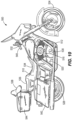
- FIG. 10 illustrates a motorcycle 500 according to an embodiment of the invention.
- the motorcycle 500 includes a frame 512 that supports an engine 516, a drivetrain 520, a front wheel 524, a rear wheel 528, a pair of footrests 530 (e.g., pegs, footboards), a handlebar assembly 532, and a seat 510.
- the engine 516 is mounted to the frame 512 and the drivetrain 520 connects the engine 516 to the rear wheel 528 such that the engine 516 powers the rotation of the rear wheel 528.
- the engine 516 can be an internal combustion engine having an inherent vibration characteristic. In other embodiments, the engine 516 may be replaced with an electric motor.
- the seat 510 includes a first or operator support region 534, a second or passenger support region 536, and a back support 538.
- the handlebar assembly 532 includes a pair of handgrips 540.
- the motorcycle 500 also includes hard saddlebags 542 and a center-mounted luggage compartment in the form of a trunk 544 mounted to the frame 512.
- the footrest assembly 530, the first and second operator support regions 534, 536 of the seat 510, the back support 538, the handgrips 540, and the like each define a touch point for the operator of the motorcycle 500. Any of the support pads 22, 122, 222, 322, 422, described in detail above, may be incorporated in any of the touch points of the motorcycle to reduce vibration and improve comfort for the operator.
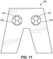
- FIG. 11 illustrates a rider wearable 600 such as pants.
- the rider wearable 600 may include one or more support cavities 638 that a support pad 622 may be received or incorporated within.
- the support pad 622 may be similar to any of the support pads 22, 122, 222, 322, 422 described in detail above.
- the support pad 622 may be incorporated into types of rider wearables such as helmets, jackets, gloves, or the like.
Landscapes
- Engineering & Computer Science (AREA)
- Mechanical Engineering (AREA)
- Aviation & Aerospace Engineering (AREA)
- Transportation (AREA)
- Mattresses And Other Support Structures For Chairs And Beds (AREA)
- Seats For Vehicles (AREA)
Abstract
Description
- Portions of a vehicle such as seats, foot supports, grips, or the like may define a touch point for an operator of the vehicle (e.g., motorcycles, all-terrain vehicles, etc.). For seats, foam is typically used as the main component. During extended use or long trips, the seat foam may compress in response to the riding conditions and require a long time to return to its original form. When compressed, the material's shock absorption characteristics are compromised.
- In one aspect, the invention provides a vehicle seat including a seat base, a seat foam supported by the seat base, a support pad positioned between the seat base and at least a portion of the seat foam, the support pad being formed of a combination of a first material and a second material, and a seat cover covering the support pad and the seat foam. The first material has a first recovery hysteresis and the second material has a second recovery hysteresis that is less than the first recovery hysteresis.
- In another aspect, the invention provides a vehicle seat including a seat base, a seat foam supported by the seat base, a support pad positioned between the seat base and at least a portion of the seat foam. The support pad including an elastomer skeleton, and a gel overmold section on the elastomer skeleton. A seat cover covering the support pad and the seat foam.
- In another aspect, the invention provides a method of assembling a seat for a vehicle. The method including providing a seat base, providing a seat foam supported by the seat base, forming a support pad of an elastomer skeleton and a gel overmold section on the skeleton, positioning the support pad between the seat base and at least a portion of the seat foam, and covering the support pad and the seat foam to the seat base with a seat cover.
- Other aspects of the invention will become apparent by consideration of the detailed description and accompanying drawings.
-
-
FIG. 1 is a perspective view of a seat for a vehicle according to an embodiment of the invention. -
FIG. 2 is a cross-sectional view of the seat about a line 2-2 inFIG. 1 . -
FIG. 3 is a perspective, exploded view of the seat ofFIG. 1 . -
FIG. 4 is a perspective view of a support pad of the seat ofFIG. 1 -
FIG. 5 is a perspective isolated view of a portion the support pad ofFIG. 4 . -
FIG. 6 is a perspective isolated view of a portion of a support pad according to another embodiment of the invention. -
FIG. 7 is a perspective isolated view of a portion of a support pad according to another embodiment of the invention. -
FIG. 8 is a perspective isolated view of a portion of a support pad according to another embodiment of the invention. -
FIG. 9 is a perspective isolated view of a portion of a support pad according to another embodiment of the invention. -
FIG. 10 is a perspective view of a motorcycle according to an embodiment of the invention. -
FIG. 11 is a schematic view of a rider wearable according to an embodiment of the invention. - Before any embodiments of the invention are explained in detail, it is to be understood that the invention is not limited in its application to the details of construction and the arrangement of components set forth in the following description or illustrated in the accompanying drawings. The invention is capable of other embodiments and of being practiced or of being carried out in various ways.
-
FIGS. 1-3 illustrate aseat 10 for a vehicle such as a motorcycle. In the illustrated embodiment, theseat 10 has a saddle-shaped geometry, which an operator straddles when operating the vehicle. As shown inFIGS. 2 and3 , theseat 10 includes aseat base 14, aseat foam 18 supported by theseat base 14, asupport pad 22 positioned between theseat base 14 and at least a portion of theseat foam 18, and aseat cover 26 covering thesupport pad 22 and theseat foam 18 to secure thesupport pad 22 and theseat foam 18 to theseat base 14. Theseat base 14 may be formed of a rigid material such as polypropylene plastic, or the like and may be secured to the vehicle (e.g., such as a motorcycle). Theseat base 14 also includes one or more apertures (not shown) formed in the base 14 (e.g., as a cut-out, molded, or the like). The apertures may be in communication with a cooling device (e.g., a seat air conditioner) to provide climate control to theseat 10. It should be appreciated that theseat 10 described in detail herein may be used for other vehicles such as scooters, bicycles, all-terrain vehicles, or the like. Features may be adapted for automobiles, etc. - With continued reference to
FIGS. 2 and3 , theseat foam 18 is shaped to be supported by the seat base 14 (e.g., has a corresponding saddle-shaped geometry). Theseat foam 18 defines anoperator support region 34 at a top side where an operator may be supported when seated on the vehicle (e.g., all or a majority of weight of the operator). Theseat foam 18 also defines an internal cavity 38 (FIG. 3 ) that is sized to receive thesupport pad 22. In the illustrated embodiment, theinternal cavity 38 is positioned at a bottom side opposite theoperator support region 34. Theseat foam 18 may be formed of open-cell polyurethane foam, closed-cell polyurethane foam, or the like. - The
support pad 22 is positioned within theinternal cavity 38 so thesupport pad 22 underlies all or a majority of theoperator support region 34. In other embodiments, thesupport pad 22 may have a geometry that corresponds with and covers theentire seat base 14. Thesupport pad 22 also includes securingprotrusions 40 that selectively engage withrecesses 44 formed in theseat base 14, which prevents movement of thesupport pad 22 relative to theseat base 14. In other embodiments, theseat base 14 may include protrusions that engage with recesses on thesupport pad 22. In other words, one of theseat base 14 or thesupport pad 22 includes a securing protrusion and the other of theseat base 14 or thesupport pad 22 includes a recess to receive the securing protrusion. - The
seat cover 26 surrounds the top side of theseat foam 18 and is secured to theseat base 14 to secure theseat foam 18 and thesupport pad 22 to theseat base 14. The seat cover may be formed of vinyl, leather or the like. Theseat cover 26 may be removably coupled to theseat base 14 such that theseat foam 18 and thesupport pad 22 can be removed from theseat base 14. In some embodiments, theseat foam 18 and thesupport pad 22 may be replaced with a replacement seat foam and/or a replacement support pad. In other embodiments, an alternative seat assembly may be retrofitted include thesupport pad 22. For example, thesupport pad 22 may positioned between a seat base and a seat foam of the alternative seat assembly. - As described in more detail below, the construction of the
seat 10 improves the support provided to the operator during operation of the vehicle. During use, when a stress under a compressive load is imposed on the seat, the material does not immediately respond or return to its original shape. Upon removal of the compressive load, the materials of the seat usually recover to its original state, but slowly, and incompletely. The ratio of the final shape dimension over the initial shape dimension after the compressive load is removed with respect to time may be referred to herein as the compliance recovery, or creep recovery. It is preferable to use the reverse percentage term of these expressions herein defined as recovery hysteresis. Recovery hysteresis can be expressed as the ratio of the initial shape dimension minus the final shape dimension to the initial shape dimension after the load is removed with respect to time. For example, compliance recovery and creep recovery are related to recovery hysteresis by the reverse percentage (1 - x), where x is the recovery hysteresis ratio. - Typically, the higher the recovery hysteresis, the more cushion or less rigid the seat is when the operator is seated. In the illustrated
vehicle seat 10, the construction of theseat 10 creates a lower seat recovery hysteresis that does not sacrifice the desired seat cushion and is less rigid when the operator is seated compared to other vehicle seats. However, increasing the recovery hysteresis also increases the recovery time for the material to obtain its original shape. Further, the construction of theseat 10 has a fast seat recovery time with lower seat recovery hysteresis that better maintains the seat's designed shape compared to other vehicle seats. It is also important to consider the environmental conditions that a vehicle seat might be subjected to. In cold weather or hot, vehicle seats that are exposed to a variety of weather conditions must support the operator with comfort and low recovery hysteresis. In the illustratedvehicle seat 10, the materials of thesupport pad 22 have low glass transition temperatures (e.g., below that of the coldest weather conditions) to provide performance in cold weather. In addition, the materials of thesupport pad 22 also have high temperature materials that can resist softening in warm weather, which provides stability of performance. Together, the low and high service temperature ranges of the materials of thesupport pad 22 provides improved vehicle seat performance for the operator in all weather conditions compared to other vehicle seats. For example, the materials of thesupport pad 22 do not stiffen under extreme low temperatures (e.g., until the temperature reaches -72 °F) and do not soften as much with extreme heat (e.g., at temperatures over 100 °F or until the temperature reaches between 210 °F and 400 °F). As such, the performance of thevehicle seat 10 is more stable through a larger range of temperature than other vehicle seats. - Further, it should be appreciated that the recovery hysteresis and/or the recovery time may vary based on the temperature, amount of load applied to the material, frequencies of the load provided to the material and the like. To determine the recovery hysteresis, a creep recovery test may be conducted, which plots a function of strain or deformation of the material against time. During the creep recovery test, prescribed loading and unloading of the material is performed and the amount of deformation of the material remaining after unloading corresponds to the recovery hysteresis. Further, the load on the material is increased to determine the load required to create irrecoverable deformation of the material. The ratio of the initial shape dimension over the final shape dimension when the irrecoverable deformation begins corresponds to the modulus of elasticity limit. Therefore, it should be appreciated that the recovery hysteresis ranges provided herein are under a first set prescribed conditions (e.g., not overloaded, within a prescribed temperature range, etc.) and the modulus of elasticity limit are provided under a second set of prescribed conditions (e.g., overloaded, within a prescribed temperature range, etc.).
- Other seats known in the art (e.g., formed of open-cell polyurethane foam, closed-cell polyurethane foam, or the like) typically have a high recovery hysteresis (e.g., between 10-30 percent) in order to allow the seat to compress during dynamic events. However, over extended use the seats tend to compress repeatedly without full recovery, which reduces cushioning or absorption for the operator. In addition, the standard seats tend to have slow recovery times (e.g., up to multiple hours) for the seat to obtain its original size due to the high recovery hysteresis. In the illustrated embodiment, the
seat foam 18 has a recovery hysteresis of at least 10 percent. - In contrast to other seats known in the art, the combination of the
seat foam 18 and thesupport pad 22 allows theseat 10 to be tuned to different required performance parameters (e.g., stiffness, dampening, or the like) during the manufacturing process of theseat 10. Further, thesupport pad 22 is formed as a combination of a first material and second material to further tune the performance of theseat 10 during the manufacturing process. For example, the size, the shape, and/or the amount of the first or second materials in thesupport pad 22 may be adjusted to tune thesupport pad 22 and theoverall seat 10 to the desired performance parameters. As such, it should be appreciated that thesupport pad 22 illustrated inFIGS. 2-9 are exemplary embodiments of the ofsupport pad 22 and that the shape, the size, and the amount of the first and second material may be adjusted to accommodate a desired application. - Now with reference to
FIGS. 4 and 5 , thesupport pad 22 includes askeleton 42 and anovermold section 46 on theskeleton 42. Theskeleton 42 may be an elastomer skeleton formed of a first material such as one or more polymers comprise polysiloxane with substituents of methyl, trifluoropropyl, or phenyl, ethylene-propylene copolymer, ethylene-propylene-diene terpolymer or polymer, acrylonitrile-butadiene copolymer, styrene-butadiene copolymer, isoprene polymer, isobutylene-isoprene copolymer, chloroprene polymer, butadiene polymer, chlorinated polyethylene polymer, epichlorohydrin polymer, ethylene-acrylic copolymer, polyacrylate copolymers, ethylene-vinyl acetate copolymer, polypropylene oxide copolymer, polyether-urethane polymer, polyester-urethane polymer, or a combination thereof. Theskeleton 42 provides improved vibration dampening, a higher recovery speed, a lower recovery hysteresis, a lower heat retention, and an improved durability within theoperator support region 34 relative to seatfoam 18. Specifically, theskeleton 42 has a first recovery hysteresis in a range from 3 to 10 percent and a first modulus of elasticity limit of not greater than 25 percent in compression. - The
skeleton 42 includes abody portion 50 defining a planar surface and a plurality ofwall portions 54 extending from thebody portion 50. The plurality ofwall portions 54 define a repeated pattern having a network ofchannels 58 defined therebetween. In the illustrated embodiment, thewall portions 54 extend from each side of thebody portion 50. In other embodiments, thewall portions 54 may extend from a single side of thebody portion 50. In addition, the predetermined pattern is a series of polygonal (e.g., hexagonal)wall portions 54. Thewall portions 50 further definevertices 60 of the polygon andvalleys 61 between thevertices 60. The network of channels 58 (e.g., pockets, recesses, or the like) are formed betweenadjacent wall portions 54 and extend continuously between the vertices (e.g., through the valleys 61). Therefore, the network ofchannels 58 are in continuous communication so theovermold section 46 can be formed continuously throughout or encapsulated within the network ofchannels 58. In other embodiments, the predetermined pattern may be a series of triangles, squares, circles, or the like. Theskeleton 42 can also include anaperture 62 formed in thebody portion 50 within (e.g., in between) the predetermined pattern defined by thewall portions 54. Theaperture 62 allows airflow through thesupport pad 22. In other embodiments, theskeleton 42 may have an alternative geometry. - The
overmold section 46 may be formed of a thixotropic material such as a polymeric gel that is typically based on liquid polymers in combination with an inorganic filler. The polymers can be polysiloxane, polybutadiene, or any type synthetic or natural liquid polymer. Since theovermold section 46 is thixotropic, the material may liquefy (e.g., when shaken stirred, or otherwise disturbed), which allows the material to be inserted within the network ofchannels 58. In some embodiments, theovermold 46 may be agel overmold section 46. Theovermold section 46 provides improved vibration dampening, a very low recovery hysteresis, and low stiffness relative to theseat foam 18. In some embodiments, theovermold section 46 has a second recovery hysteresis in a range from 1 to 5 percent and a first modulus of elasticity range limit of not greater than 50 percent in compression. Therefore, combining the two materials within thesingle support pad 22, allows for the performance parameters of thesupport pad 22 to be tuned to a desired stiffness, and recovery hysteresis. - The combination of the
seat foam 18 and thesupport pad 22 inseat 10 allows theseat 10 to have low hysteresis loss during dynamic riding events, which increases a recovery speed of theseat 10, improves the vibration dampening of theseat 10, and reduces heat retention of theseat 10. In the illustrated embodiment, theseat 10 has a spring rate in a range of 1.0 lbf/in/in2 to 8.0 lbf/in/in2. Adjusting the size, shape, and construction of thesupport pad 22 within theseat 10 may adjust the spring rate of theseat 10. -
FIG. 6 illustrates a portion of asupport pad 122 according to another embodiment of the invention. Thesupport pad 122 is similar to thesupport pad 22 shown inFIG. 1-5 and described above. Therefore, like features are identified with like reference numerals plus "100", and only the differences between the two will be discussed. - The
support pad 122 includes askeleton 142 and anovermold section 146 on theskeleton 142. Theskeleton 142 includes abody portion 150 defining a planar surface and a plurality ofwall portions 154 extending from thebody portion 150. The plurality ofwall portions 154 define a repeated pattern having an array ofchannels 158 defined therein. In the illustrated embodiment, the predetermined pattern is a series of polygonal (e.g., hexagonal)wall portions 154. Thewall portions 150 further definevertices 160 of the polygon andvalleys 161 between thevertices 160. The array ofchannels 158 are formed at thevertices 160 of the polygonal. Further, the array ofchannel 158 are in discontinuous (e.g., do not extend through the valleys 161) and define three columns extending from thevertices 160. Therefore, theovermold section 146 is separately formed or encapsulated within each of the array ofchannels 158. In addition, theovermold section 146 is also formed on portions of thebody portion 150 of theskeleton 142. It should be appreciated thatovermold section 146 may also be formed on theentire skeleton 142. Theskeleton 142 also includes anaperture 162 formed in thebody portion 150 within the predetermined pattern defined by thewall portions 154. Theaperture 162 allows airflow through thesupport pad 122. -
FIG. 7 illustrates a portion of asupport pad 222 according to another embodiment of the invention. Thesupport pad 222 is similar to thesupport pad 22 shown inFIG. 1-5 and described above. Therefore, like features are identified with like reference numerals plus "200", and only the differences between the two will be discussed. - The
support pad 222 includes askeleton 242 and anovermold section 246 on theskeleton 242. Theskeleton 242 includes a plurality ofwall portions 254 defining a repeated pattern that is separated by a network ofchannels 258 defined therebetween. In the illustrated embodiment, the predetermined pattern is a series of polygonal (e.g., hexagonal)wall portions 254 having an array ofchannels 264 defined within the repeated pattern. Theovermold section 246 is formed or encapsulated within the array network ofchannels 264 defined within the repeated pattern, while the network ofchannels 258 is devoid of theovermold section 246. -
FIG. 8 illustrates a portion of asupport pad 322 according to another embodiment of the invention. Thesupport pad 322 is similar to thesupport pad 22 shown inFIG. 1-5 and described above. Therefore, like features are identified with like reference numerals plus "300", and only the differences between the two will be discussed. - The
support pad 322 includes askeleton 342 and anovermold section 346 on theskeleton 342. Theelastomer skeleton 342 includes a plurality ofwall portions 354 defining a repeated pattern that is separated by a network ofchannels 358 defined therebetween. In the illustrated embodiment, the predetermined pattern is a series of polygonal (e.g., hexagonal)wall portions 354 having an array ofchannels 364 defined within the repeated pattern. Theovermold section 346 is formed or encapsulated within the first network ofchannels 358, while the array ofchannels 364 is devoid of theovermold section 346. -
FIG. 9 illustrates a portion of asupport pad 422 according to another embodiment of the invention. Thesupport pad 422 is similar to thesupport pad 22 shown inFIG. 1-5 and described above. Therefore, like features are identified with like reference numerals plus "400", and only the differences between the two will be discussed. - The
support pad 422 includes askeleton 442 and anovermold section 446 on theskeleton 442. Theskeleton 442 includes abody portion 450 and a plurality ofwall portions 454 extending from thebody portion 450. The plurality ofwall portions 454 define a repeated pattern having an array of channels 458 defined therein. In the illustrated embodiment, the predetermined pattern is a series of discontinuous polygonal (e.g., hexagonal)wall portions 154. Thewall portions 454 define thevertices 460 of the polygon and are separated byrecesses 470. Theovermold section 446 is formed or encapsulated within each of the array of channels 458. In addition, theovermold section 446 is also formed on at least a portion of thebody portion 450 of theskeleton 442. Theskeleton 442 also includes anaperture 462 formed in thebody portion 450 within the predetermined pattern defined by thewall portions 454. Theaperture 462 allows airflow through thesupport pad 422. -
FIG. 10 illustrates amotorcycle 500 according to an embodiment of the invention. Themotorcycle 500 includes aframe 512 that supports anengine 516, adrivetrain 520, afront wheel 524, arear wheel 528, a pair of footrests 530 (e.g., pegs, footboards), ahandlebar assembly 532, and aseat 510. Theengine 516 is mounted to theframe 512 and thedrivetrain 520 connects theengine 516 to therear wheel 528 such that theengine 516 powers the rotation of therear wheel 528. Theengine 516 can be an internal combustion engine having an inherent vibration characteristic. In other embodiments, theengine 516 may be replaced with an electric motor. In the illustrated embodiment, theseat 510 includes a first oroperator support region 534, a second orpassenger support region 536, and aback support 538. Thehandlebar assembly 532 includes a pair ofhandgrips 540. Themotorcycle 500 also includeshard saddlebags 542 and a center-mounted luggage compartment in the form of atrunk 544 mounted to theframe 512. Thefootrest assembly 530, the first and secondoperator support regions seat 510, theback support 538, thehandgrips 540, and the like each define a touch point for the operator of themotorcycle 500. Any of thesupport pads -
FIG. 11 illustrates a rider wearable 600 such as pants. The rider wearable 600 may include one ormore support cavities 638 that asupport pad 622 may be received or incorporated within. It should be appreciated that thesupport pad 622 may be similar to any of thesupport pads support pad 622 may be incorporated into types of rider wearables such as helmets, jackets, gloves, or the like. - Various aspects of the invention are set forth in the following claims.
Claims (15)
- A vehicle seat comprising:a seat base;a seat foam supported by the seat base;a support pad positioned between the seat base and at least a portion of the seat foam, the support pad being formed of a combination of a first material and a second material; anda seat cover covering the support pad and the seat foam,wherein the first material has a first recovery hysteresis and the second material has a second recovery hysteresis that is less than the first recovery hysteresis.
- A vehicle seat comprising:a seat base;a seat foam supported by the seat base;a support pad positioned between the seat base and at least a portion of the seat foam, the support pad including:an elastomer skeleton; anda gel overmold section on the elastomer skeleton; anda seat cover covering the support pad and the seat foam.
- The vehicle seat of claim 1 or 2, wherein the seat foam includes a cavity defined therein to receive the support pad.
- The vehicle seat of claim 3, wherein the seat foam defines an operator support region at a top side, and wherein the cavity is positioned at a bottom side opposite the operator support region.
- The vehicle seat of claim 1, wherein the first recovery hysteresis is in a range from 3 to 10 percent and the second recovery hysteresis is in a range from 1 to 5 percent.
- The vehicle seat of claim 1, wherein the first material has a first modulus of elasticity limit and the second material has a second modulus of elasticity limit, and wherein the first modulus of elasticity limit is less than the second modulus of elasticity limit.
- The vehicle seat of claim 6, wherein the first modulus of elasticity limit is less than 25 percent and the second modulus of elasticity limit is less than 50 percent.
- The vehicle seat of claim 1, wherein the first material is an elastomer providing a skeleton of the support pad and the second material of the support pad is a gel provided as an overmold section on the skeleton.
- The vehicle seat of claim 8, wherein the gel is thixotropic and based on liquid polymers in combination with an inorganic filler.
- The vehicle seat of one of claims 2 or 8, wherein the skeleton includes a body portion and a plurality of wall portions extending from the body portion, and wherein the plurality of wall portions define a repeated pattern having a network of channels.
- The vehicle seat of claim 10, wherein the overmold section is encapsulated within the network of channels.
- The vehicle seat of claim 10 or 11, wherein the overmold section is on at least a portion of the body portion of the skeleton.
- The vehicle seat of claim one of claims 1 to 12, wherein the seat has a saddle-shaped structure.
- A method of assembling a seat for a vehicle, the method comprising:providing a seat base;providing a seat foam supported by the seat base;forming a support pad of an elastomer skeleton and a gel overmold section on the skeleton;positioning the support pad between the seat base and at least a portion of the seat foam; andcovering the support pad and the seat foam to the seat base with a seat cover.
- The method of claim 14, further comprising positioning the support pad within a cavity formed in the seat foam.
Applications Claiming Priority (1)
| Application Number | Priority Date | Filing Date | Title |
|---|---|---|---|
| US17/541,840 US11780523B2 (en) | 2021-12-03 | 2021-12-03 | Multi-material support pad |
Publications (2)
| Publication Number | Publication Date |
|---|---|
| EP4190630A1 true EP4190630A1 (en) | 2023-06-07 |
| EP4190630B1 EP4190630B1 (en) | 2025-11-12 |
Family
ID=84360283
Family Applications (1)
| Application Number | Title | Priority Date | Filing Date |
|---|---|---|---|
| EP22208301.6A Active EP4190630B1 (en) | 2021-12-03 | 2022-11-18 | Multi-material support pad |
Country Status (3)
| Country | Link |
|---|---|
| US (1) | US11780523B2 (en) |
| EP (1) | EP4190630B1 (en) |
| JP (1) | JP2023083244A (en) |
Citations (3)
| Publication number | Priority date | Publication date | Assignee | Title |
|---|---|---|---|---|
| US5203607A (en) * | 1990-12-11 | 1993-04-20 | Supracor Systems, Inc. | Bicycle seat |
| WO2015129753A1 (en) * | 2014-02-26 | 2015-09-03 | テイ・エス テック株式会社 | Saddle-type seat |
| US20190291802A1 (en) * | 2018-03-21 | 2019-09-26 | Ddk Group Co., Ltd. Taiwan Branch | Bike saddle incorporating with bio-gel structure |
Family Cites Families (68)
| Publication number | Priority date | Publication date | Assignee | Title |
|---|---|---|---|---|
| US1851973A (en) * | 1930-02-10 | 1932-04-05 | Troxel Mfg Company | Cycle saddle |
| US5108076A (en) * | 1986-02-24 | 1992-04-28 | Chiarella Michele A | Anatomical multilayer bicycle seat |
| US4952439A (en) * | 1988-10-14 | 1990-08-28 | Alden Laboratories | Padding device |
| JP2919854B2 (en) * | 1989-05-09 | 1999-07-19 | ヤマハ発動機株式会社 | Riding vehicle |
| US5016941A (en) * | 1990-03-13 | 1991-05-21 | Tachi-S Co. Ltd. | Structure of vehicle seat |
| US5749111A (en) | 1996-02-14 | 1998-05-12 | Teksource, Lc | Gelatinous cushions with buckling columns |
| JP2000217658A (en) * | 1999-01-29 | 2000-08-08 | Deruta Tsuuringu:Kk | Structure of cushion |
| US8828293B2 (en) | 2000-03-15 | 2014-09-09 | C-Eng Co., Ltd. | Apparatus and method for manufacturing three-dimensional netted structure |
| US9169585B2 (en) | 2000-03-15 | 2015-10-27 | C-Eng Co., Ltd. | Three dimensional netted structure |
| US9194066B2 (en) | 2000-03-15 | 2015-11-24 | C-Eng Co., Ltd. | Three dimensional netted structure |
| US7625629B2 (en) | 2000-03-15 | 2009-12-01 | C-Eng Co., Ltd. | Three-dimensional net-like structure, and method and device for producing three dimensional net-like structure |
| US9174404B2 (en) | 2000-03-15 | 2015-11-03 | C-Eng Co., Ltd. | Method for manufacturing three-dimensional netted structure |
| US8757996B2 (en) | 2000-03-15 | 2014-06-24 | C-Eng Co., Ltd. | Apparatus and method for manufacturing three-dimensional netted structure |
| US8563121B2 (en) | 2000-03-15 | 2013-10-22 | C-Eng Co., Ltd. | Three-dimensional netted structure having four molded surfaces |
| US10328618B2 (en) | 2000-03-15 | 2019-06-25 | C-Eng Co., Ltd. | Three dimensional netted structure |
| US8277210B2 (en) | 2000-03-15 | 2012-10-02 | C-Eng Co., Ltd. | Apparatus and method for manufacturing three-dimensional netted structure |
| US6625830B2 (en) * | 2001-10-02 | 2003-09-30 | Neal Lampel | Wheelchair cushion |
| JP2004073429A (en) | 2002-08-15 | 2004-03-11 | Nhk Spring Co Ltd | Breathable sheet |
| TWI257908B (en) * | 2003-11-14 | 2006-07-11 | Selle Tech Ind Co Ltd | Improved bicycle seat |
| US7622179B2 (en) | 2004-03-17 | 2009-11-24 | Dow Global Technologies Inc. | Three dimensional random looped structures made from interpolymers of ethylene/α-olefins and uses thereof |
| US7032967B2 (en) * | 2004-07-30 | 2006-04-25 | Pyzik Matthew R | Structural foam and urethane composite for use in a motorcycle seat and method of manufacturing the same |
| DE102004052076B4 (en) | 2004-10-26 | 2007-10-11 | W.L. Gore & Associates Gmbh | vehicle seat |
| US7722116B2 (en) | 2006-02-28 | 2010-05-25 | Clarion Co. Ltd. | Acoustic seat vibratory-bone-conduction type |
| US20070246157A1 (en) * | 2006-04-25 | 2007-10-25 | Technogel Gmbh & Co. | Process for preparing an apparatus comprising a gel layer |
| US8607387B2 (en) | 2006-11-20 | 2013-12-17 | Stryker Corporation | Multi-walled gelastic mattress system |
| US7730566B2 (en) | 2006-11-20 | 2010-06-08 | Gaymar Industries, Inc. | Multi-walled gelastic material |
| JP5099325B2 (en) | 2007-08-24 | 2012-12-19 | 株式会社川島織物セルコン | Elastic body support equipment |
| US8549684B2 (en) | 2008-03-25 | 2013-10-08 | Stryker Corporation | Gelastic material having variable or same hardness and balanced, independent buckling in a mattress system |
| US9603461B2 (en) | 2008-10-03 | 2017-03-28 | Edizone, Llc | Breathable gel |
| US8932692B2 (en) | 2008-10-03 | 2015-01-13 | Edizone, Llc | Cushions comprising deformable members and related methods |
| US8359689B2 (en) * | 2009-04-24 | 2013-01-29 | Fxi, Inc. | Mattress adapted for supporting heavy weight persons |
| WO2010135550A2 (en) | 2009-05-21 | 2010-11-25 | Edizone, Llc | Cushions comprising deformable members and related methods |
| JP2011177227A (en) | 2010-02-26 | 2011-09-15 | Honda Motor Co Ltd | Vehicular seat, watercraft seat, method for making vehicular seat, and method for making watercraft seat |
| US8919750B2 (en) | 2011-08-16 | 2014-12-30 | Edizone, Llc | Cushioning elements comprising buckling walls and methods of forming such cushioning elements |
| KR20130067823A (en) | 2011-12-14 | 2013-06-25 | 히로코 오사키 | 3-dimensional net materials |
| JP5985411B2 (en) | 2012-02-22 | 2016-09-06 | トヨタ紡織株式会社 | Cushion pad for vehicle seat |
| CH706858B1 (en) | 2012-08-08 | 2019-03-15 | Bigolin Giuseppe | Breathable saddle for cycles, motorcycles or pedal machines. |
| JP5339107B1 (en) | 2013-02-27 | 2013-11-13 | 東洋紡株式会社 | Network structure with excellent compression durability |
| JP5459436B1 (en) | 2013-04-26 | 2014-04-02 | 東洋紡株式会社 | Network structure with excellent thermal dimensional stability |
| WO2015050134A1 (en) | 2013-10-01 | 2015-04-09 | 東洋紡株式会社 | Net-shaped structure having excellent compression durability |
| JP5569641B1 (en) | 2013-10-28 | 2014-08-13 | 東洋紡株式会社 | Elastic network structure with excellent quietness and lightness |
| TWI639549B (en) | 2013-10-29 | 2018-11-01 | 東洋紡股份有限公司 | Reticular structure having excellent compression durability |
| JP5459439B1 (en) | 2013-11-18 | 2014-04-02 | 東洋紡株式会社 | Network structure with excellent thermal dimensional stability |
| JP5459438B1 (en) | 2013-11-18 | 2014-04-02 | 東洋紡株式会社 | Network structure with excellent thermal dimensional stability |
| JP6188218B2 (en) | 2013-12-11 | 2017-08-30 | 東洋ゴム工業株式会社 | Manufacturing method of seat pad |
| JP2015112231A (en) | 2013-12-11 | 2015-06-22 | 東洋ゴム工業株式会社 | Method for manufacturing seat pad |
| JP6294140B2 (en) | 2014-04-22 | 2018-03-14 | 長瀬産業株式会社 | Cushion structure, cushion structure component, and method of manufacturing cushion structure |
| JP6440998B2 (en) | 2014-08-25 | 2018-12-19 | 株式会社タチエス | Headrest and vehicle seat |
| JP6472651B2 (en) * | 2014-12-12 | 2019-02-20 | テイ・エス テック株式会社 | Vehicle seat |
| US11871861B2 (en) | 2015-03-09 | 2024-01-16 | Purple Innovation, Llc | Cushions comprising a non-slip elastomeric cushioning element |
| WO2017110529A1 (en) | 2015-12-22 | 2017-06-29 | 株式会社タチエス | Vehicle seat |
| US9801075B2 (en) | 2016-02-29 | 2017-10-24 | Hughes Network Systems, Llc | Sizing satellite beam capacity |
| JP6572801B2 (en) * | 2016-03-03 | 2019-09-11 | テイ・エス テック株式会社 | Vehicle seat |
| US12435768B2 (en) | 2016-03-07 | 2025-10-07 | Purple Innovation, Llc | Elastomeric cushion members including perforated skins and related methods |
| US20170251824A1 (en) | 2016-03-07 | 2017-09-07 | Purple Innovation, Llc | Cushions including a coated elastomeric cushioning element and related methods |
| US10863837B2 (en) | 2016-09-21 | 2020-12-15 | Purple Innovation, Llc | Pillow including gelatinous elastomer cushioning materials |
| US10772445B2 (en) | 2016-09-21 | 2020-09-15 | Purple Innovation, Llc | Pillow including gelatinous elastomer cushion having deformable wall members and related methods |
| JP6568881B2 (en) | 2017-01-23 | 2019-08-28 | 本田技研工業株式会社 | Vehicle seat structure |
| US12096858B2 (en) | 2017-07-20 | 2024-09-24 | Purple Innovation, Llc | Cushions including a coated elastomeric cushioning element and related methods |
| JP7062061B2 (en) | 2017-11-17 | 2022-05-16 | パープル イノベーション,エルエルシー | Manufacturing method of buffer |
| US11229298B2 (en) | 2017-11-17 | 2022-01-25 | Purple Innovation, Llc | Cushions including one or more reinforced portions and related methods |
| JP6680813B2 (en) | 2018-01-31 | 2020-04-15 | 本田技研工業株式会社 | Vehicle seat structure |
| US10882576B2 (en) * | 2018-03-21 | 2021-01-05 | Ddk Group Co., Ltd., Taiwan Branch | Bike saddle incorporating with bio-gel structure |
| DE202018004424U1 (en) | 2018-06-27 | 2019-09-30 | I.G. Bauerhin Gmbh | Insert for the seat air conditioning of a seat and / or backrest cushion and seat and / or backrest cushion with such insert |
| US10486760B1 (en) | 2018-09-20 | 2019-11-26 | AB Inventions, LLC | Seat with downwardly-slanted bump-less nose |
| CA3055743C (en) | 2018-09-20 | 2022-08-16 | AB Inventions, LLC | Seat with downwardly-slanted bump-less nose |
| DE202019104930U1 (en) | 2019-09-06 | 2019-11-18 | Ddk Group Co., Ltd. Taiwan Branch | Interchangeable saddle structure |
| DE202020001983U1 (en) | 2020-05-07 | 2020-07-02 | Sqlab Gmbh | Bicycle saddle cover |
-
2021
- 2021-12-03 US US17/541,840 patent/US11780523B2/en active Active
-
2022
- 2022-11-18 EP EP22208301.6A patent/EP4190630B1/en active Active
- 2022-11-30 JP JP2022191041A patent/JP2023083244A/en active Pending
Patent Citations (3)
| Publication number | Priority date | Publication date | Assignee | Title |
|---|---|---|---|---|
| US5203607A (en) * | 1990-12-11 | 1993-04-20 | Supracor Systems, Inc. | Bicycle seat |
| WO2015129753A1 (en) * | 2014-02-26 | 2015-09-03 | テイ・エス テック株式会社 | Saddle-type seat |
| US20190291802A1 (en) * | 2018-03-21 | 2019-09-26 | Ddk Group Co., Ltd. Taiwan Branch | Bike saddle incorporating with bio-gel structure |
Also Published As
| Publication number | Publication date |
|---|---|
| EP4190630B1 (en) | 2025-11-12 |
| JP2023083244A (en) | 2023-06-15 |
| US20230174182A1 (en) | 2023-06-08 |
| US11780523B2 (en) | 2023-10-10 |
Similar Documents
| Publication | Publication Date | Title |
|---|---|---|
| EP3450288B1 (en) | Memory saddle with double elastic foam assembly for vibration absorption | |
| US6942291B2 (en) | Bicycle saddle | |
| EP1731059A1 (en) | Seat for vehicle | |
| EP2363319B1 (en) | Vehicular seat and method for making the same | |
| US11603155B2 (en) | Bicycle saddle, saddle pad, and method for producing a bicycle saddle or saddle pad | |
| US20230219474A1 (en) | Additively manufactured cushion component | |
| JP2016510277A5 (en) | ||
| EP1792815B1 (en) | Seat for vehicle and seat for watercraft | |
| JP2001161489A (en) | Vehicular seat | |
| EP4190630A1 (en) | Multi-material support pad | |
| EP0718144B1 (en) | Vehicle seat | |
| JP2000205333A (en) | Vibration mitigation unit and sheet using vibration mitigation unit | |
| EP0713900B1 (en) | Shock absorbing material and vehicle seat using the shock absorbing material | |
| US20180009352A1 (en) | Seat pan and seat | |
| US10857908B2 (en) | Side extension device for seat of vehicle | |
| GB2607058A (en) | A vehicle seat sub-assembly and method | |
| JP3463182B2 (en) | Vehicle seat | |
| US9079458B2 (en) | Tire blocks | |
| CN2324039Y (en) | air cushion bicycle saddle | |
| US10576862B1 (en) | Head restraint for vehicle passenger seat | |
| JPH08150976A (en) | Motorcycle seats | |
| EP0516592B1 (en) | Improved-comfort bycicle saddle | |
| JPH0336466Y2 (en) | ||
| JPH08323071A (en) | Shock absorber, cushion body provided with the same, and vehicle seat | |
| JP2000072069A (en) | Vehicle seat cushion |
Legal Events
| Date | Code | Title | Description |
|---|---|---|---|
| PUAI | Public reference made under article 153(3) epc to a published international application that has entered the european phase |
Free format text: ORIGINAL CODE: 0009012 |
|
| STAA | Information on the status of an ep patent application or granted ep patent |
Free format text: STATUS: THE APPLICATION HAS BEEN PUBLISHED |
|
| AK | Designated contracting states |
Kind code of ref document: A1 Designated state(s): AL AT BE BG CH CY CZ DE DK EE ES FI FR GB GR HR HU IE IS IT LI LT LU LV MC ME MK MT NL NO PL PT RO RS SE SI SK SM TR |
|
| STAA | Information on the status of an ep patent application or granted ep patent |
Free format text: STATUS: REQUEST FOR EXAMINATION WAS MADE |
|
| 17P | Request for examination filed |
Effective date: 20231121 |
|
| RBV | Designated contracting states (corrected) |
Designated state(s): AL AT BE BG CH CY CZ DE DK EE ES FI FR GB GR HR HU IE IS IT LI LT LU LV MC ME MK MT NL NO PL PT RO RS SE SI SK SM TR |
|
| P01 | Opt-out of the competence of the unified patent court (upc) registered |
Free format text: CASE NUMBER: APP_48078/2024 Effective date: 20240821 |
|
| GRAP | Despatch of communication of intention to grant a patent |
Free format text: ORIGINAL CODE: EPIDOSNIGR1 |
|
| STAA | Information on the status of an ep patent application or granted ep patent |
Free format text: STATUS: GRANT OF PATENT IS INTENDED |
|
| INTG | Intention to grant announced |
Effective date: 20250116 |
|
| GRAJ | Information related to disapproval of communication of intention to grant by the applicant or resumption of examination proceedings by the epo deleted |
Free format text: ORIGINAL CODE: EPIDOSDIGR1 |
|
| STAA | Information on the status of an ep patent application or granted ep patent |
Free format text: STATUS: REQUEST FOR EXAMINATION WAS MADE |
|
| INTC | Intention to grant announced (deleted) | ||
| GRAP | Despatch of communication of intention to grant a patent |
Free format text: ORIGINAL CODE: EPIDOSNIGR1 |
|
| STAA | Information on the status of an ep patent application or granted ep patent |
Free format text: STATUS: GRANT OF PATENT IS INTENDED |
|
| INTG | Intention to grant announced |
Effective date: 20250620 |
|
| GRAS | Grant fee paid |
Free format text: ORIGINAL CODE: EPIDOSNIGR3 |
|
| GRAA | (expected) grant |
Free format text: ORIGINAL CODE: 0009210 |
|
| STAA | Information on the status of an ep patent application or granted ep patent |
Free format text: STATUS: THE PATENT HAS BEEN GRANTED |
|
| AK | Designated contracting states |
Kind code of ref document: B1 Designated state(s): AL AT BE BG CH CY CZ DE DK EE ES FI FR GB GR HR HU IE IS IT LI LT LU LV MC ME MK MT NL NO PL PT RO RS SE SI SK SM TR |
|
| REG | Reference to a national code |
Ref country code: CH Ref legal event code: F10 Free format text: ST27 STATUS EVENT CODE: U-0-0-F10-F00 (AS PROVIDED BY THE NATIONAL OFFICE) Effective date: 20251112 Ref country code: GB Ref legal event code: FG4D |
|
| REG | Reference to a national code |
Ref country code: IE Ref legal event code: FG4D |
|
| REG | Reference to a national code |
Ref country code: DE Ref legal event code: R096 Ref document number: 602022024820 Country of ref document: DE |
|
| PGFP | Annual fee paid to national office [announced via postgrant information from national office to epo] |
Ref country code: AT Payment date: 20260113 Year of fee payment: 4 |
|
| REG | Reference to a national code |
Ref country code: NL Ref legal event code: MP Effective date: 20251112 |
|
| PG25 | Lapsed in a contracting state [announced via postgrant information from national office to epo] |
Ref country code: ES Free format text: LAPSE BECAUSE OF FAILURE TO SUBMIT A TRANSLATION OF THE DESCRIPTION OR TO PAY THE FEE WITHIN THE PRESCRIBED TIME-LIMIT Effective date: 20251112 |
|
| REG | Reference to a national code |
Ref country code: LT Ref legal event code: MG9D |
|
| PG25 | Lapsed in a contracting state [announced via postgrant information from national office to epo] |
Ref country code: NO Free format text: LAPSE BECAUSE OF FAILURE TO SUBMIT A TRANSLATION OF THE DESCRIPTION OR TO PAY THE FEE WITHIN THE PRESCRIBED TIME-LIMIT Effective date: 20260212 |
|
| PG25 | Lapsed in a contracting state [announced via postgrant information from national office to epo] |
Ref country code: HR Free format text: LAPSE BECAUSE OF FAILURE TO SUBMIT A TRANSLATION OF THE DESCRIPTION OR TO PAY THE FEE WITHIN THE PRESCRIBED TIME-LIMIT Effective date: 20251112 Ref country code: FI Free format text: LAPSE BECAUSE OF FAILURE TO SUBMIT A TRANSLATION OF THE DESCRIPTION OR TO PAY THE FEE WITHIN THE PRESCRIBED TIME-LIMIT Effective date: 20251112 Ref country code: AT Free format text: LAPSE BECAUSE OF FAILURE TO SUBMIT A TRANSLATION OF THE DESCRIPTION OR TO PAY THE FEE WITHIN THE PRESCRIBED TIME-LIMIT Effective date: 20251112 |
|
| REG | Reference to a national code |
Ref country code: AT Ref legal event code: MK05 Ref document number: 1856485 Country of ref document: AT Kind code of ref document: T Effective date: 20251112 |
|
| PG25 | Lapsed in a contracting state [announced via postgrant information from national office to epo] |
Ref country code: NL Free format text: LAPSE BECAUSE OF FAILURE TO SUBMIT A TRANSLATION OF THE DESCRIPTION OR TO PAY THE FEE WITHIN THE PRESCRIBED TIME-LIMIT Effective date: 20251112 |
|
| PG25 | Lapsed in a contracting state [announced via postgrant information from national office to epo] |
Ref country code: RS Free format text: LAPSE BECAUSE OF FAILURE TO SUBMIT A TRANSLATION OF THE DESCRIPTION OR TO PAY THE FEE WITHIN THE PRESCRIBED TIME-LIMIT Effective date: 20260212 |
|
| PG25 | Lapsed in a contracting state [announced via postgrant information from national office to epo] |
Ref country code: IS Free format text: LAPSE BECAUSE OF FAILURE TO SUBMIT A TRANSLATION OF THE DESCRIPTION OR TO PAY THE FEE WITHIN THE PRESCRIBED TIME-LIMIT Effective date: 20260312 |
|
| PGFP | Annual fee paid to national office [announced via postgrant information from national office to epo] |
Ref country code: FR Payment date: 20260330 Year of fee payment: 4 |
|
| PG25 | Lapsed in a contracting state [announced via postgrant information from national office to epo] |
Ref country code: PT Free format text: LAPSE BECAUSE OF FAILURE TO SUBMIT A TRANSLATION OF THE DESCRIPTION OR TO PAY THE FEE WITHIN THE PRESCRIBED TIME-LIMIT Effective date: 20260312 |
|
| PG25 | Lapsed in a contracting state [announced via postgrant information from national office to epo] |
Ref country code: PL Free format text: LAPSE BECAUSE OF FAILURE TO SUBMIT A TRANSLATION OF THE DESCRIPTION OR TO PAY THE FEE WITHIN THE PRESCRIBED TIME-LIMIT Effective date: 20251112 |
|
| PG25 | Lapsed in a contracting state [announced via postgrant information from national office to epo] |
Ref country code: LV Free format text: LAPSE BECAUSE OF FAILURE TO SUBMIT A TRANSLATION OF THE DESCRIPTION OR TO PAY THE FEE WITHIN THE PRESCRIBED TIME-LIMIT Effective date: 20251112 |