EP4190609A1 - Electric drive assembly for electric vehicle, and electric vehicle - Google Patents
Electric drive assembly for electric vehicle, and electric vehicle Download PDFInfo
- Publication number
- EP4190609A1 EP4190609A1 EP22210923.3A EP22210923A EP4190609A1 EP 4190609 A1 EP4190609 A1 EP 4190609A1 EP 22210923 A EP22210923 A EP 22210923A EP 4190609 A1 EP4190609 A1 EP 4190609A1
- Authority
- EP
- European Patent Office
- Prior art keywords
- shaft
- drive assembly
- gear
- electric
- input shaft
- Prior art date
- Legal status (The legal status is an assumption and is not a legal conclusion. Google has not performed a legal analysis and makes no representation as to the accuracy of the status listed.)
- Ceased
Links
Images

Classifications
-
- B—PERFORMING OPERATIONS; TRANSPORTING
- B60—VEHICLES IN GENERAL
- B60K—ARRANGEMENT OR MOUNTING OF PROPULSION UNITS OR OF TRANSMISSIONS IN VEHICLES; ARRANGEMENT OR MOUNTING OF PLURAL DIVERSE PRIME-MOVERS IN VEHICLES; AUXILIARY DRIVES FOR VEHICLES; INSTRUMENTATION OR DASHBOARDS FOR VEHICLES; ARRANGEMENTS IN CONNECTION WITH COOLING, AIR INTAKE, GAS EXHAUST OR FUEL SUPPLY OF PROPULSION UNITS IN VEHICLES
- B60K17/00—Arrangement or mounting of transmissions in vehicles
- B60K17/22—Arrangement or mounting of transmissions in vehicles characterised by arrangement, location, or type of main drive shafting, e.g. cardan shaft
-
- F—MECHANICAL ENGINEERING; LIGHTING; HEATING; WEAPONS; BLASTING
- F16—ENGINEERING ELEMENTS AND UNITS; GENERAL MEASURES FOR PRODUCING AND MAINTAINING EFFECTIVE FUNCTIONING OF MACHINES OR INSTALLATIONS; THERMAL INSULATION IN GENERAL
- F16H—GEARING
- F16H37/00—Combinations of mechanical gearings, not provided for in groups F16H1/00 - F16H35/00
- F16H37/02—Combinations of mechanical gearings, not provided for in groups F16H1/00 - F16H35/00 comprising essentially only toothed or friction gearings
- F16H37/06—Combinations of mechanical gearings, not provided for in groups F16H1/00 - F16H35/00 comprising essentially only toothed or friction gearings with a plurality of driving or driven shafts; with arrangements for dividing torque between two or more intermediate shafts
- F16H37/08—Combinations of mechanical gearings, not provided for in groups F16H1/00 - F16H35/00 comprising essentially only toothed or friction gearings with a plurality of driving or driven shafts; with arrangements for dividing torque between two or more intermediate shafts with differential gearing
- F16H37/0806—Combinations of mechanical gearings, not provided for in groups F16H1/00 - F16H35/00 comprising essentially only toothed or friction gearings with a plurality of driving or driven shafts; with arrangements for dividing torque between two or more intermediate shafts with differential gearing with a plurality of driving or driven shafts
- F16H37/0813—Combinations of mechanical gearings, not provided for in groups F16H1/00 - F16H35/00 comprising essentially only toothed or friction gearings with a plurality of driving or driven shafts; with arrangements for dividing torque between two or more intermediate shafts with differential gearing with a plurality of driving or driven shafts with only one input shaft
-
- B—PERFORMING OPERATIONS; TRANSPORTING
- B60—VEHICLES IN GENERAL
- B60B—VEHICLE WHEELS; CASTORS; AXLES FOR WHEELS OR CASTORS; INCREASING WHEEL ADHESION
- B60B35/00—Axle units; Parts thereof ; Arrangements for lubrication of axles
- B60B35/12—Torque-transmitting axles
- B60B35/14—Torque-transmitting axles composite or split, e.g. half- axles; Couplings between axle parts or sections
-
- B—PERFORMING OPERATIONS; TRANSPORTING
- B60—VEHICLES IN GENERAL
- B60K—ARRANGEMENT OR MOUNTING OF PROPULSION UNITS OR OF TRANSMISSIONS IN VEHICLES; ARRANGEMENT OR MOUNTING OF PLURAL DIVERSE PRIME-MOVERS IN VEHICLES; AUXILIARY DRIVES FOR VEHICLES; INSTRUMENTATION OR DASHBOARDS FOR VEHICLES; ARRANGEMENTS IN CONNECTION WITH COOLING, AIR INTAKE, GAS EXHAUST OR FUEL SUPPLY OF PROPULSION UNITS IN VEHICLES
- B60K1/00—Arrangement or mounting of electrical propulsion units
-
- B—PERFORMING OPERATIONS; TRANSPORTING
- B60—VEHICLES IN GENERAL
- B60K—ARRANGEMENT OR MOUNTING OF PROPULSION UNITS OR OF TRANSMISSIONS IN VEHICLES; ARRANGEMENT OR MOUNTING OF PLURAL DIVERSE PRIME-MOVERS IN VEHICLES; AUXILIARY DRIVES FOR VEHICLES; INSTRUMENTATION OR DASHBOARDS FOR VEHICLES; ARRANGEMENTS IN CONNECTION WITH COOLING, AIR INTAKE, GAS EXHAUST OR FUEL SUPPLY OF PROPULSION UNITS IN VEHICLES
- B60K17/00—Arrangement or mounting of transmissions in vehicles
- B60K17/04—Arrangement or mounting of transmissions in vehicles characterised by arrangement, location or kind of gearing
- B60K17/06—Arrangement or mounting of transmissions in vehicles characterised by arrangement, location or kind of gearing of change-speed gearing
- B60K17/08—Arrangement or mounting of transmissions in vehicles characterised by arrangement, location or kind of gearing of change-speed gearing of mechanical type
-
- B—PERFORMING OPERATIONS; TRANSPORTING
- B60—VEHICLES IN GENERAL
- B60K—ARRANGEMENT OR MOUNTING OF PROPULSION UNITS OR OF TRANSMISSIONS IN VEHICLES; ARRANGEMENT OR MOUNTING OF PLURAL DIVERSE PRIME-MOVERS IN VEHICLES; AUXILIARY DRIVES FOR VEHICLES; INSTRUMENTATION OR DASHBOARDS FOR VEHICLES; ARRANGEMENTS IN CONNECTION WITH COOLING, AIR INTAKE, GAS EXHAUST OR FUEL SUPPLY OF PROPULSION UNITS IN VEHICLES
- B60K17/00—Arrangement or mounting of transmissions in vehicles
- B60K17/04—Arrangement or mounting of transmissions in vehicles characterised by arrangement, location or kind of gearing
- B60K17/16—Arrangement or mounting of transmissions in vehicles characterised by arrangement, location or kind of gearing of differential gearing
- B60K17/165—Arrangement or mounting of transmissions in vehicles characterised by arrangement, location or kind of gearing of differential gearing provided between independent half axles
-
- B—PERFORMING OPERATIONS; TRANSPORTING
- B60—VEHICLES IN GENERAL
- B60K—ARRANGEMENT OR MOUNTING OF PROPULSION UNITS OR OF TRANSMISSIONS IN VEHICLES; ARRANGEMENT OR MOUNTING OF PLURAL DIVERSE PRIME-MOVERS IN VEHICLES; AUXILIARY DRIVES FOR VEHICLES; INSTRUMENTATION OR DASHBOARDS FOR VEHICLES; ARRANGEMENTS IN CONNECTION WITH COOLING, AIR INTAKE, GAS EXHAUST OR FUEL SUPPLY OF PROPULSION UNITS IN VEHICLES
- B60K1/00—Arrangement or mounting of electrical propulsion units
- B60K2001/001—Arrangement or mounting of electrical propulsion units one motor mounted on a propulsion axle for rotating right and left wheels of this axle
-
- F—MECHANICAL ENGINEERING; LIGHTING; HEATING; WEAPONS; BLASTING
- F16—ENGINEERING ELEMENTS AND UNITS; GENERAL MEASURES FOR PRODUCING AND MAINTAINING EFFECTIVE FUNCTIONING OF MACHINES OR INSTALLATIONS; THERMAL INSULATION IN GENERAL
- F16H—GEARING
- F16H1/00—Toothed gearings for conveying rotary motion
- F16H1/02—Toothed gearings for conveying rotary motion without gears having orbital motion
- F16H1/20—Toothed gearings for conveying rotary motion without gears having orbital motion involving more than two intermeshing members
- F16H1/22—Toothed gearings for conveying rotary motion without gears having orbital motion involving more than two intermeshing members with a plurality of driving or driven shafts; with arrangements for dividing torque between two or more intermediate shafts
-
- F—MECHANICAL ENGINEERING; LIGHTING; HEATING; WEAPONS; BLASTING
- F16—ENGINEERING ELEMENTS AND UNITS; GENERAL MEASURES FOR PRODUCING AND MAINTAINING EFFECTIVE FUNCTIONING OF MACHINES OR INSTALLATIONS; THERMAL INSULATION IN GENERAL
- F16H—GEARING
- F16H1/00—Toothed gearings for conveying rotary motion
- F16H1/28—Toothed gearings for conveying rotary motion with gears having orbital motion
- F16H2001/2881—Toothed gearings for conveying rotary motion with gears having orbital motion comprising two axially spaced central gears, i.e. ring or sun gear, engaged by at least one common orbital gear wherein one of the central gears is forming the output
-
- F—MECHANICAL ENGINEERING; LIGHTING; HEATING; WEAPONS; BLASTING
- F16—ENGINEERING ELEMENTS AND UNITS; GENERAL MEASURES FOR PRODUCING AND MAINTAINING EFFECTIVE FUNCTIONING OF MACHINES OR INSTALLATIONS; THERMAL INSULATION IN GENERAL
- F16H—GEARING
- F16H48/00—Differential gearings
- F16H48/06—Differential gearings with gears having orbital motion
- F16H48/08—Differential gearings with gears having orbital motion comprising bevel gears
Definitions
- the disclosure relates to the technical field of electric drive assemblies, and in particular provides an electric drive assembly for an electric vehicle, and an electric vehicle.
- Electric vehicles are clean energy vehicles, and are therefore becoming a major development trend with the vigorous promotion of energy conservation and emission reduction.
- Electric drive assemblies are important components in new energy vehicles.
- An existing electric drive assembly usually consists of three relatively independent parts: an electric motor, a controller and a transmission gearbox.
- the transmission gearbox is an essential part of the electric vehicle, the design form of the transmission gearbox structure is critical.
- most of the transmission gearboxes of new energy vehicles are of a parallel shaft structure, and there are also a small number of gearboxes of a coaxial structure, such as an offset coaxial structure and a planetary gearset coaxial structure. In the process of configuring the transmission gearbox, the problems of noise, vibration and harshness should also be considered.
- the commonly used gearbox of an offset coaxial structure has a large center distance, so it is not conducive to the X-direction spatial layout of the vehicle and also not conducive to the design of high rotation speed and high output torque.
- the traditional gearbox of a planetary gearset coaxial structure has a small center distance, but there are a lot of gears, and there are also ring gears difficult to process, the overall NVH (noise, vibration and harshness) problems of the gearbox are difficult to solve, and the required parts and components are expensive to manufacture.
- the disclosure provides a transmission gearbox for an electric vehicle, the transmission gearbox comprising a gearbox input shaft and intermediate shafts, wherein one end of the gearbox input shaft is configured to be connectable to an electric motor of the electric vehicle, and a sidewall of the gearbox input shaft is provided with a first-stage driving gear; and there are three intermediate shafts which are evenly distributed outside and around an axis of the gearbox input shaft, each intermediate shaft is provided with a first-stage driven gear, and the three first-stage driven gears are respectively meshed with the first-stage driving gear.
- the transmission gearbox further comprises a second-stage driven gear, coaxially disposed with the gearbox input shaft, each intermediate shaft is provided with a second-stage driving gear, the three second-stage driving gears are respectively meshed with the second-stage driven gear, such that the first-stage driving gear, the first-stage driven gear, the second-stage driving gears, and the second-stage driven gear together form a two-stage three-intermediate-shaft coaxial gear set.
- the gearbox input shaft is provided with a central through hole.
- the disclosure further provides an electric drive assembly for an electric vehicle, the electric drive assembly further comprising an electric motor, a differential, a first axle shaft, a second axle shaft, a first wheel and a second wheel, wherein
- the output shaft of the electric motor is integrally formed with the gearbox input shaft.
- the second-stage driven gear and the differential are integrally welded to each other or are connected to each other via bolts.
- the transmission gearbox further comprises a casing, the gearbox input shaft passes through the casing and is then connected to the output shaft of the electric motor, and the differential is disposed inside the casing and is connected to the second-stage driven gear.
- the gearbox input shaft is connected to the differential via a bearing.
- the first axle shaft and/or the second axle shaft are/is connected to the axle shaft gear(s) of the differential via splines.
- the disclosure further provides an electric vehicle, comprising an electric drive assembly for an electric vehicle according to any one of the foregoing technical solutions.
- an electric drive assembly for an electric vehicle is provided, the electric drive assembly being provided with a transmission gearbox, wherein the transmission gearbox comprises a gearbox input shaft and intermediate shafts, wherein one end of the gearbox input shaft is configured to be connectable to an electric motor of the electric vehicle, and a sidewall of the gearbox input shaft is provided with a first-stage driving gear; and there are three intermediate shafts which are evenly distributed outside and around an axis of the gearbox input shaft, each intermediate shaft is provided with a first-stage driven gear, and the three first-stage driven gears are respectively meshed with the first-stage driving gear.
- the three intermediate shafts of the disclosure are coaxial, and there is no need to design a ring gear, so that the spatial layout of the vehicle is facilitated while providing a good NVH performance, and a bracket for supporting the differential is also omitted, enabling a simple structure and lower costs.
- the coaxial structure having three intermediate shafts has a smaller center distance while providing the same output torque, the reduction of the center distance enables reduction of the diameters of the gears and the shafts, so the gear width can be reduced.
- Such a design is more conducive to the design of high-speed rotating members.
- the torque is shared by the three intermediate shafts, and the lightweight design of the geared shaft is thus ensured while providing higher output torque.
- the disclosure generally makes the center distance smaller, the space occupied in the vehicle is smaller, fewer gear sets are used, the overall NVH performance is better, and the machining difficulty reduced as no ring gear is involved, so that the production and assembly costs can be significantly reduced.
- first and second axle shafts may also be connected to the differential by means of a gear or a coupling in an interference fit with a shaft, i.e., by means of a flat key, as long as the arrangement ensures that the first and second axle shafts are connected in a cooperative manner.
- the terms “install”, “interface” and “connect” are to be understood in a broad sense, for example, it can be a fixed connection, detachable connection, or integral connection; a mechanical connection or electrical connection; a direct connection or indirect connection through an intermediate medium, and internal communication between two elements, unless expressly specified and defined otherwise.
- install can be a fixed connection, detachable connection, or integral connection; a mechanical connection or electrical connection; a direct connection or indirect connection through an intermediate medium, and internal communication between two elements, unless expressly specified and defined otherwise.
- the specific meaning of the above-mentioned terms in the disclosure can be interpreted according to the specific situation.
- the disclosure provides an electric drive assembly for an electric vehicle.
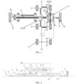
- the electric drive assembly for the electric vehicle comprises a transmission gearbox 5.
- the transmission gearbox 5 is provided with a gearbox input shaft 1 and intermediate shafts 2.
- One end of the gearbox input shaft 1 is configured to be connectable to an electric motor 4 (obscured and not shown in Fig. 1 , and briefly shown in Fig. 2 ) of the electric vehicle, and a sidewall of the gearbox input shaft 1 is provided with a first-stage driving gear 11.
- the transmission gearbox 5 further comprises a second-stage driven gear 31.
- the second-stage driven gear 31 is coaxially disposed with the gearbox input shaft 1, each intermediate shaft 2 is provided with a second-stage driving gear 12, the three second-stage driving gears 12 are respectively meshed with the second-stage driven gear 31, such that the first-stage driving gear 11, the first-stage driven gears 21, the second-stage driving gears 12, and the second-stage driven gear 31 together form a two-stage three-intermediate-shaft coaxial gear set, thereby enhancing the stability of its overall gear transmission efficiency.
- the gearbox input shaft 1 is further provided with a central through hole 13.
- the transmission gearbox 5 is provided with the three intermediate shafts 2, the provision of the three intermediate shafts 2 enables a force to be divided into three components to be transferred, such that a larger torque is transferred, and the design of the intermediate shafts 2, the number of which is set to three, is more conducive to the stability of the gearbox.
- the even distribution of the three intermediate shafts 2 outside and aound the axis of the gearbox input shaft 1 has the following advantages: first, the arrangement of the three intermediate shafts 2 enables an inner ring gear to be omitted, which has low precision and large error deformation and is difficult to machine, so that the difficulty of production can be reduced while saving costs; and the use of the structure of the two-stage three-intermediate-shaft coaxial gear set facilitates the change in the rotation speed and the generation of low noise, and the NVH performance of the electric drive system can be significantly improved.
- the output torque of the output shaft 10 of the electric motor is constant, the torque is the product of the force and the force arm, and the output shaft 10 of the electric motor transmits the same force to the intermediate shaft(s) 2; therefore, the torque required by the traditional offset intermediate shaft 2 is larger, while the three intermediate shafts 2 will equally share a certain force, and the required torque is smaller. Therefore, the center distance of the gears of the three intermediate shafts 2 is smaller than the center distance of the conventional offset coaxial electric drive assembly, and the reduction of the center distance enables reduction of the diameters of the gears and the shafts, thereby reducing the cost. Compared with the traditional electric drive assembly, the use of the three intermediate shafts 2 enables reduction of the gear width. Although three intermediate shafts 2 are used, the overall volume and weight are reduced. In addition, the design of the three intermediate shafts 2 makes the volume of the electric drive assembly smaller, which is more conducive to the layout of the vehicle.
- the electric drive assembly of the disclosure further comprises an electric motor 4, a differential 3, a first axle shaft 6, a second axle shaft 8, a first wheel 7 and a second wheel 9, which work together with the transmission gearbox 5.
- the transmission gearbox 5 comprises the gearbox input shaft 1 and the intermediate shafts 2.
- a first end of the gearbox input shaft 1 is configured to be connectable to the electric motor 4 of the electric vehicle, and a sidewall of the gearbox input shaft 1 is provided with a first-stage driving gear 11.
- the three intermediate shafts 2 are evenly distributed outside and around an axis of the gearbox input shaft 1, each intermediate shaft 2 is provided with a first-stage driven gear 21, and the three first-stage driven gears 21 are respectively meshed with the first-stage driving gear 11.
- the transmission gearbox 5 further comprises a second-stage driven gear 31.
- the second-stage driven gear 31 is coaxially disposed with the gearbox input shaft 1, and a sidewall of a first end of the second-stage driven gear 31 is provided with the second-stage driven gear 31.
- Each intermediate shaft 2 is provided with a second-stage driving gear 12, the three second-stage driving gears 12 are respectively meshed with the second-stage driven gear 31, such that the first-stage driving gear 11, the first-stage driven gears 21, the second-stage driving gears 12, and the second-stage driven gear 31 together form a two-stage three-intermediate-shaft coaxial gear set.
- the gearbox input shaft 1 is further provided with a central through hole 13.
- An electric motor output shaft 10 of the electric motor 4 is connected to the gearbox input shaft 1, the gearbox input shaft 1 is connected to the second-stage driven gear 31 via the intermediate shafts 2, and the second-stage driven gear 31 is connected to the differential 3.
- One end of the first axle shaft 6 passes through the central hole 13 and is then connected to a first end axle shaft gear 32 of the differential 3, and the other end of the first axle shaft 6 is connected to the first wheel 7.
- One end of the second axle shaft 8 is connected to a second end axle shaft gear 33 of the differential 3, and the other end of the second axle shaft 8 is connected to the second wheel 9.
- the gearbox input shaft 1 is connected to the electric motor 4 of the electric vehicle, the first-stage driving gear 11 on the gearbox input shaft 1 is meshed with the first-stage driven gears 21 on the three intermediate shafts 2, and the second-stage driven gear 31 is meshed with the second-stage driving gears 12 on the three intermediate shafts 2, so as to form the two-stage three-intermediate-shaft coaxial gear set together.
- the second-stage driven gear 31 can further reduce the speed of the electric motor output shaft 10, so that the speed of the electric motor output shaft 10 is matched with that of the wheel.
- the central through hole 13 provided in the gearbox input shaft 1 enables the first axle shaft 6 to directly pass through the central through hole 13, so that one end of the first axle shaft 6 passes through the central through hole 13 and is directly connected to one end of the differential 3, and the other end of the first axle shaft is connected to the first wheel 7.
- One end of the second axle shaft 8 is directly connected to the differential 3, and the other end thereof is directly connected to the second wheel 9. Therefore, the electric motor 4 directly drives the gearbox input shaft 1 to rotate, and simultaneously drives the three intermediate shafts 2 to move.
- This design of the central through hole 13 is more efficient and saves costs.
- the design of the structure of the two-stage three-intermediate-shaft coaxial gear set facilitates the spatial layout of the vehicle while providing a good NVH performance, and a bracket for supporting the differential 3 is also omitted, enabling a simple structure and lower costs.
- a design compared with the offset coaxial design, such a design has a smaller center distance while providing the same output torque, the reduction of the center distance enables reduction of the diameters of the gears and the shafts, so the gear width can be reduced.
- Such a design is more conducive to the design of high-speed rotating members. The torque is shared by the three intermediate shafts 2, and the lightweight design of the geared shaft is thus ensured while providing higher output torque.
- the arrangement of the structure having three intermediate shafts 2 enables the input shaft and the output shaft to be evenly loaded, reduces friction, improves the transmission efficiency, and also facilitates product serialization.
- the electric motor output shaft 10 and the gearbox input shaft 1 are integrally formed.
- This design of integrally forming the electric motor output shaft 10 and the gearbox input shaft 1 eliminates the need for intermediate connecting components, reduces costs, enables the electric motor 4 to be directly output to the gearbox input shaft 1, and reduces the number of parts.
- the second-stage driven gear 31 and the differential 3 are integrally welded to each other. This arrangement eliminates the need for additional parts, and can also achieve the effect of reducing costs, and the reduction in quantity also brings more stable product performance.
- the transmission gearbox 5 further comprises a casing 51, the gearbox input shaft 1 passes through the casing 51 and is then connected to the electric motor output shaft 10, and the differential 3 is disposed inside the casing 51 and is connected to the second-stage driven gear 31.
- This arrangement omits a bracket for supporting the differential 3, the structure is simple, the miniaturization of the whole machine is realized, and the purpose of reducing the cost is achieved.
- the gearbox input shaft 1 is connected to the differential 3 via a bearing 14.
- first axle shaft 6 and/or the second axle shaft 8 are/is connected to the differential 3 in such a way that the first axle shaft 6 is connected to the first end axle shaft gear 32 of the differential 3 via splines and the second axle shaft 8 is connected to the second end axle shaft gear 33 of the differential 3 via splines. This arrangement is easier and more stable during connection and operation.
- the disclosure provides an electric drive assembly for an electric vehicle, the electric drive assembly being provided with a transmission gearbox 5.
- the transmission gearbox 5 comprises a gearbox input shaft 1 and intermediate shafts 2.
- One end of the gearbox input shaft 1 is configured to be connectable to an electric motor 4 of the electric vehicle, and a sidewall of the gearbox input shaft 1 is provided with a first-stage driving gear 11.
- the three intermediate shafts 2 are evenly distributed outside and around an axis of the gearbox input shaft 1, each intermediate shaft 2 is provided with a first-stage driven gear 21, and the three first-stage driven gears 21 are respectively meshed with the first-stage driving gear 11.
- the second-stage driven gear 31 is coaxially disposed with the gearbox input shaft 1, each intermediate shaft 2 is provided with a second-stage driving gear 12, the three second-stage driving gears 12 are respectively meshed with the second-stage driven gear 31, such that the first-stage driving gear 11, the first-stage driven gears 21, the second-stage driving gears 12, and the second-stage driven gear 31 together form a two-stage three-intermediate-shaft coaxial gear set.
- this arrangement does not require high development cost, reduces the manufacturing cost of parts and components, reduces the number of parts and components and eliminates the need for too many high precision parts and components.
- the structure having a larger ring gear, namely a smaller gear and a larger ring gear, is simplified, so there is no need to provide an inner ring gear which is difficult to machine, and the three intermediate shafts 2 and the gearbox input shaft 1 cooperate together to form the two-stage three-intermediate-shaft coaxial gear set.
- This arrangement can significantly improve the NVH performance of the electric drive system.
- the arrangement of the central through hole 13 in the gearbox input shaft 1 can omit a bracket for supporting the differential 3, which not only has a simple structure, but also reduces the cost.
- the center distance of the gears of the three intermediate shafts 2 is smaller than that of the conventional offset coaxial electric drive assembly, and the reduction of the center distance enables reduction of the diameters of the gears and the shafts.
- the coaxial structure having three intermediate shafts 2 has a smaller center distance while providing the same output torque, the smaller center distance is more conducive to the design of high-speed rotating members; the torque is shared by the three intermediate shafts 2, and the lightweight design of the geared shaft is thus ensured while providing higher output torque; and the use of the three intermediate shafts 2 enables reduction of the gear width.
- the overall volume and weight are reduced.
- the design of the three intermediate shafts 2 makes the volume of the electric drive assembly smaller, which is more conducive to the layout of the vehicle.
- the structure having three intermediate shafts 2 enables the input shaft and the output shaft to be evenly loaded, reduces friction, and improves the transmission efficiency.
- the structure having three intermediate shafts 2 enables easy adjustment of the bearing capacity by appropriately increasing the gear width without changing the center distance, further facilitating product serialization.
- connection between the electric motor output shaft 10 and the gearbox input shaft 1 may be of an integrated design, or the electric motor output shaft 10 may be coupled to the gearbox input shaft 1 via splines, as long as the matching and connection between the electric motor output shaft 10 and the gearbox input shaft 1 can be achieved.
- the disclosure further provides an electric vehicle having an electric drive assembly for an electric vehicle according to any one of the foregoing implementations.
Landscapes
- Engineering & Computer Science (AREA)
- Mechanical Engineering (AREA)
- Chemical & Material Sciences (AREA)
- Combustion & Propulsion (AREA)
- Transportation (AREA)
- General Engineering & Computer Science (AREA)
- Gear Transmission (AREA)
- Retarders (AREA)
Abstract
Description
- The disclosure relates to the technical field of electric drive assemblies, and in particular provides an electric drive assembly for an electric vehicle, and an electric vehicle.
- Electric vehicles are clean energy vehicles, and are therefore becoming a major development trend with the vigorous promotion of energy conservation and emission reduction. Electric drive assemblies are important components in new energy vehicles. An existing electric drive assembly usually consists of three relatively independent parts: an electric motor, a controller and a transmission gearbox. As the transmission gearbox is an essential part of the electric vehicle, the design form of the transmission gearbox structure is critical. At present, most of the transmission gearboxes of new energy vehicles are of a parallel shaft structure, and there are also a small number of gearboxes of a coaxial structure, such as an offset coaxial structure and a planetary gearset coaxial structure. In the process of configuring the transmission gearbox, the problems of noise, vibration and harshness should also be considered. At present, the commonly used gearbox of an offset coaxial structure has a large center distance, so it is not conducive to the X-direction spatial layout of the vehicle and also not conducive to the design of high rotation speed and high output torque. The traditional gearbox of a planetary gearset coaxial structure has a small center distance, but there are a lot of gears, and there are also ring gears difficult to process, the overall NVH (noise, vibration and harshness) problems of the gearbox are difficult to solve, and the required parts and components are expensive to manufacture.
- Accordingly, there is a need in the art for a new gearbox structure for an electric vehicle to solve the problems of noise, vibration and harshness of the existing gearbox of a planetary gearset coaxial structure, and the problems of a large number of gears to be meshed, the difficulty of precise control and the high manufacturing cost of parts and components, as well as the problem of the gearbox of an offset coaxial structure requiring a larger center distance to transmit the same torque.
- In order to solve the above problems in the prior art, that is, in order to solve the poor noise, vibration and harshness performance of the gearbox of a planetary gearset coaxial structure, and the problem of the gearbox with the offset coaxial structure requiring a larger center distance to transmit the same torque, the disclosure provides a transmission gearbox for an electric vehicle, the transmission gearbox comprising a gearbox input shaft and intermediate shafts, wherein one end of the gearbox input shaft is configured to be connectable to an electric motor of the electric vehicle, and a sidewall of the gearbox input shaft is provided with a first-stage driving gear; and there are three intermediate shafts which are evenly distributed outside and around an axis of the gearbox input shaft, each intermediate shaft is provided with a first-stage driven gear, and the three first-stage driven gears are respectively meshed with the first-stage driving gear.
- In a preferred technical solution of the transmission gearbox for an electric vehicle, the transmission gearbox further comprises a second-stage driven gear, coaxially disposed with the gearbox input shaft, each intermediate shaft is provided with a second-stage driving gear, the three second-stage driving gears are respectively meshed with the second-stage driven gear, such that the first-stage driving gear, the first-stage driven gear, the second-stage driving gears, and the second-stage driven gear together form a two-stage three-intermediate-shaft coaxial gear set.
- In a preferred technical solution of the transmission gearbox for an electric vehicle, the gearbox input shaft is provided with a central through hole.
- The disclosure further provides an electric drive assembly for an electric vehicle, the electric drive assembly further comprising an electric motor, a differential, a first axle shaft, a second axle shaft, a first wheel and a second wheel, wherein
- an output shaft of electric motor is connected to the gearbox input shaft, the gearbox input shaft is connected to the second-stage driven gear via the intermediate shafts, and the second-stage driven gear is connected to the differential;
- one end of the first axle shaft passes through the central hole and is then connected to a first end axle shaft gear of the differential, and the other end of the first axle shaft is connected to the first wheel; and
- one end of the second axle shaft is connected to a second end axle shaft gear of the differential, and the other end of the second axle shaft is connected to the second wheel.
- In a preferred technical solution of the transmission gearbox for an electric vehicle, the output shaft of the electric motor is integrally formed with the gearbox input shaft.
- In a preferred technical solution of the transmission gearbox for an electric vehicle, the second-stage driven gear and the differential are integrally welded to each other or are connected to each other via bolts.
- In a preferred technical solution of the transmission gearbox for an electric vehicle, the transmission gearbox further comprises a casing, the gearbox input shaft passes through the casing and is then connected to the output shaft of the electric motor, and the differential is disposed inside the casing and is connected to the second-stage driven gear.
- In a preferred technical solution of the transmission gearbox for an electric vehicle, the gearbox input shaft is connected to the differential via a bearing.
- In a preferred technical solution of the transmission gearbox for an electric vehicle, the first axle shaft and/or the second axle shaft are/is connected to the axle shaft gear(s) of the differential via splines.
- The disclosure further provides an electric vehicle, comprising an electric drive assembly for an electric vehicle according to any one of the foregoing technical solutions.
- It can be understood by those skilled in the art that, in the technical solutions of the disclosure, an electric drive assembly for an electric vehicle is provided, the electric drive assembly being provided with a transmission gearbox, wherein the transmission gearbox comprises a gearbox input shaft and intermediate shafts, wherein one end of the gearbox input shaft is configured to be connectable to an electric motor of the electric vehicle, and a sidewall of the gearbox input shaft is provided with a first-stage driving gear; and there are three intermediate shafts which are evenly distributed outside and around an axis of the gearbox input shaft, each intermediate shaft is provided with a first-stage driven gear, and the three first-stage driven gears are respectively meshed with the first-stage driving gear.
- Through the above arrangement, the three intermediate shafts of the disclosure are coaxial, and there is no need to design a ring gear, so that the spatial layout of the vehicle is facilitated while providing a good NVH performance, and a bracket for supporting the differential is also omitted, enabling a simple structure and lower costs. Moreover, compared with the offset coaxial design, the coaxial structure having three intermediate shafts has a smaller center distance while providing the same output torque, the reduction of the center distance enables reduction of the diameters of the gears and the shafts, so the gear width can be reduced. Such a design is more conducive to the design of high-speed rotating members. The torque is shared by the three intermediate shafts, and the lightweight design of the geared shaft is thus ensured while providing higher output torque. In addition, although there are three intermediate shafts in number, the overall volume and weight are reduced. Furthermore, the arrangement of the structure having three intermediate shafts enables the input shaft and the output shaft to be evenly loaded, reduces friction, and improves the transmission efficiency. Therefore, the disclosure generally makes the center distance smaller, the space occupied in the vehicle is smaller, fewer gear sets are used, the overall NVH performance is better, and the machining difficulty reduced as no ring gear is involved, so that the production and assembly costs can be significantly reduced.
- An electric drive assembly for an electric vehicle of the disclosure will be described below with reference to the accompanying drawings. In the accompanying drawings:
-
Fig. 1 is a schematic diagram of a force transfer path of an electric drive assembly for an electric vehicle according to the disclosure; -
Fig. 2 is a partial schematic diagram of the electric drive assembly for an electric vehicle according to the disclosure; -
Fig. 3 is a structural diagram of the electric drive assembly for an electric vehicle according to the disclosure; and -
Fig. 4 is a structural diagram of the electric drive assembly for an electric vehicle according to the disclosure. - 1 - Gearbox input shaft, 11 - First-stage driving gear, 12 - Second-stage driving gear, 13 - Central hole, 2 - Intermediate shaft, 21 - First-stage driven gear, 3 - Differential, 31 - Second-stage driven gear, 32 - First end axle shaft gear, 33 - Second end axle shaft gear, 4 - Electric motor, 5 - Transmission gearbox, 51 - Casing, 6 - First axle shaft, 7 - First wheel, 8 - Second axle shaft, 9 - Second wheel, 10 - Output shaft of the electric motor, 14 - Bearing.
- Preferred embodiments of the disclosure are described below with reference to the accompanying drawings. Those skilled in the art should understand that these implementations are only used to explain the technical principles of the disclosure, and are not intended to limit the scope of protection of the disclosure. Those skilled in the art can make adjustments according to requirements so as to adapt to specific application scenarios. For example, although in the specification, the connection between the first axle shaft and the differential, and the connection between the second axle shaft and the differential of the electric drive assembly are performed by means of splines, the first and second axle shafts may also be connected to the differential by means of a gear or a coupling in an interference fit with a shaft, i.e., by means of a flat key, as long as the arrangement ensures that the first and second axle shafts are connected in a cooperative manner.
- It should be noted that in the description of the disclosure, the terms, such as "center", "upper", "lower", "left", "right", "vertical", "horizontal", "inner" and "outer", that indicate directions or positional relationships are based on the directions or positional relationships shown in the drawings only for convenience of description, and do not indicate or imply that the device or element must have a specific orientation, be constructed and operated in a specific orientation, and therefore cannot be construed as limitation to the disclosure. In addition, the terms "first", "second", and "third" are for descriptive purposes only, and may not be interpreted as indicating or implying relative importance.
- In addition, it should also be noted that in the description of the disclosure, the terms "install", "interface" and "connect" are to be understood in a broad sense, for example, it can be a fixed connection, detachable connection, or integral connection; a mechanical connection or electrical connection; a direct connection or indirect connection through an intermediate medium, and internal communication between two elements, unless expressly specified and defined otherwise. For those skilled in the art, the specific meaning of the above-mentioned terms in the disclosure can be interpreted according to the specific situation.
- Referring first to
Figs. 1 to 4 , an electric drive assembly for an electric vehicle according to the disclosure will be described. - As shown in
Figs. 1 to 4 , in order to solve the problem of NVH in the existing electric drive assembly, as well as the problems of a large number of gears to be meshed, the difficulty of precise control, the high manufacturing cost of parts and components, and a larger center distance, the disclosure provides an electric drive assembly for an electric vehicle. The electric drive assembly for the electric vehicle comprises a transmission gearbox 5. The transmission gearbox 5 is provided with agearbox input shaft 1 andintermediate shafts 2. One end of thegearbox input shaft 1 is configured to be connectable to an electric motor 4 (obscured and not shown inFig. 1 , and briefly shown inFig. 2 ) of the electric vehicle, and a sidewall of thegearbox input shaft 1 is provided with a first-stage driving gear 11. There are three intermediate shafts 2 (one shown inFig. 2 , and three shown inFigs. 3 and 4 ). The threeintermediate shafts 2 are evenly distributed outside and around an axis of thegearbox input shaft 1, eachintermediate shaft 2 is provided with a first-stage drivengear 21, and the three first-stage drivengears 21 are respectively meshed with the first-stage driving gear 11. Preferably, in a possible implementation, the transmission gearbox 5 further comprises a second-stage drivengear 31. The second-stage drivengear 31 is coaxially disposed with thegearbox input shaft 1, eachintermediate shaft 2 is provided with a second-stage driving gear 12, the three second-stage driving gears 12 are respectively meshed with the second-stage drivengear 31, such that the first-stage driving gear 11, the first-stage drivengears 21, the second-stage driving gears 12, and the second-stage drivengear 31 together form a two-stage three-intermediate-shaft coaxial gear set, thereby enhancing the stability of its overall gear transmission efficiency. Preferably, as shown inFig. 2 , in another possible implementation, thegearbox input shaft 1 is further provided with a central throughhole 13. - As the transmission gearbox 5 is provided with the three
intermediate shafts 2, the provision of the threeintermediate shafts 2 enables a force to be divided into three components to be transferred, such that a larger torque is transferred, and the design of theintermediate shafts 2, the number of which is set to three, is more conducive to the stability of the gearbox. Compared with the conventional electric drive assembly of an offset coaxial structure or of a planetary coaxial structure, the even distribution of the threeintermediate shafts 2 outside and aound the axis of thegearbox input shaft 1 has the following advantages: first, the arrangement of the threeintermediate shafts 2 enables an inner ring gear to be omitted, which has low precision and large error deformation and is difficult to machine, so that the difficulty of production can be reduced while saving costs; and the use of the structure of the two-stage three-intermediate-shaft coaxial gear set facilitates the change in the rotation speed and the generation of low noise, and the NVH performance of the electric drive system can be significantly improved. In addition, the output torque of theoutput shaft 10 of the electric motor is constant, the torque is the product of the force and the force arm, and theoutput shaft 10 of the electric motor transmits the same force to the intermediate shaft(s) 2; therefore, the torque required by the traditional offsetintermediate shaft 2 is larger, while the threeintermediate shafts 2 will equally share a certain force, and the required torque is smaller. Therefore, the center distance of the gears of the threeintermediate shafts 2 is smaller than the center distance of the conventional offset coaxial electric drive assembly, and the reduction of the center distance enables reduction of the diameters of the gears and the shafts, thereby reducing the cost. Compared with the traditional electric drive assembly, the use of the threeintermediate shafts 2 enables reduction of the gear width. Although threeintermediate shafts 2 are used, the overall volume and weight are reduced. In addition, the design of the threeintermediate shafts 2 makes the volume of the electric drive assembly smaller, which is more conducive to the layout of the vehicle. - Further referring to
Figs. 1 to 4 , the electric drive assembly for the electric vehicle according to the disclosure will be described below in detail. - The electric drive assembly of the disclosure further comprises an electric motor 4, a differential 3, a
first axle shaft 6, a second axle shaft 8, afirst wheel 7 and a second wheel 9, which work together with the transmission gearbox 5. The transmission gearbox 5 comprises thegearbox input shaft 1 and theintermediate shafts 2. A first end of thegearbox input shaft 1 is configured to be connectable to the electric motor 4 of the electric vehicle, and a sidewall of thegearbox input shaft 1 is provided with a first-stage driving gear 11. There are threeintermediate shafts 2. The threeintermediate shafts 2 are evenly distributed outside and around an axis of thegearbox input shaft 1, eachintermediate shaft 2 is provided with a first-stage drivengear 21, and the three first-stage driven gears 21 are respectively meshed with the first-stage driving gear 11. The transmission gearbox 5 further comprises a second-stage drivengear 31. The second-stage drivengear 31 is coaxially disposed with thegearbox input shaft 1, and a sidewall of a first end of the second-stage drivengear 31 is provided with the second-stage drivengear 31. Eachintermediate shaft 2 is provided with a second-stage driving gear 12, the three second-stage driving gears 12 are respectively meshed with the second-stage drivengear 31, such that the first-stage driving gear 11, the first-stage driven gears 21, the second-stage driving gears 12, and the second-stage drivengear 31 together form a two-stage three-intermediate-shaft coaxial gear set. Thegearbox input shaft 1 is further provided with a central throughhole 13. An electricmotor output shaft 10 of the electric motor 4 is connected to thegearbox input shaft 1, thegearbox input shaft 1 is connected to the second-stage drivengear 31 via theintermediate shafts 2, and the second-stage drivengear 31 is connected to the differential 3. One end of thefirst axle shaft 6 passes through thecentral hole 13 and is then connected to a first endaxle shaft gear 32 of the differential 3, and the other end of thefirst axle shaft 6 is connected to thefirst wheel 7. One end of the second axle shaft 8 is connected to a second endaxle shaft gear 33 of the differential 3, and the other end of the second axle shaft 8 is connected to the second wheel 9. - During the operation of the electric drive assembly, the
gearbox input shaft 1 is connected to the electric motor 4 of the electric vehicle, the first-stage driving gear 11 on thegearbox input shaft 1 is meshed with the first-stage driven gears 21 on the threeintermediate shafts 2, and the second-stage drivengear 31 is meshed with the second-stage driving gears 12 on the threeintermediate shafts 2, so as to form the two-stage three-intermediate-shaft coaxial gear set together. In addition, in addition to being meshable with second-stage driving gears 12 on theintermediate shafts 2, the second-stage drivengear 31 can further reduce the speed of the electricmotor output shaft 10, so that the speed of the electricmotor output shaft 10 is matched with that of the wheel. In addition, the central throughhole 13 provided in thegearbox input shaft 1 enables thefirst axle shaft 6 to directly pass through the central throughhole 13, so that one end of thefirst axle shaft 6 passes through the central throughhole 13 and is directly connected to one end of the differential 3, and the other end of the first axle shaft is connected to thefirst wheel 7. One end of the second axle shaft 8 is directly connected to the differential 3, and the other end thereof is directly connected to the second wheel 9. Therefore, the electric motor 4 directly drives thegearbox input shaft 1 to rotate, and simultaneously drives the threeintermediate shafts 2 to move. This design of the central throughhole 13 is more efficient and saves costs. In addition, the design of the structure of the two-stage three-intermediate-shaft coaxial gear set facilitates the spatial layout of the vehicle while providing a good NVH performance, and a bracket for supporting the differential 3 is also omitted, enabling a simple structure and lower costs. Moreover, compared with the offset coaxial design, such a design has a smaller center distance while providing the same output torque, the reduction of the center distance enables reduction of the diameters of the gears and the shafts, so the gear width can be reduced. Such a design is more conducive to the design of high-speed rotating members. The torque is shared by the threeintermediate shafts 2, and the lightweight design of the geared shaft is thus ensured while providing higher output torque. In addition, although there are threeintermediate shafts 2 in number, the overall volume and weight are reduced. Furthermore, the arrangement of the structure having threeintermediate shafts 2 enables the input shaft and the output shaft to be evenly loaded, reduces friction, improves the transmission efficiency, and also facilitates product serialization. - Further referring to
Figs. 1 to 4 , the electric drive assembly for the electric vehicle according to the disclosure will be described below in detail. - Preferably, in a possible implementation, the electric
motor output shaft 10 and thegearbox input shaft 1 are integrally formed. This design of integrally forming the electricmotor output shaft 10 and thegearbox input shaft 1 eliminates the need for intermediate connecting components, reduces costs, enables the electric motor 4 to be directly output to thegearbox input shaft 1, and reduces the number of parts. Furthermore, in a preferred implementation, the second-stage drivengear 31 and the differential 3 are integrally welded to each other. This arrangement eliminates the need for additional parts, and can also achieve the effect of reducing costs, and the reduction in quantity also brings more stable product performance. In addition, the transmission gearbox 5 further comprises a casing 51, thegearbox input shaft 1 passes through the casing 51 and is then connected to the electricmotor output shaft 10, and the differential 3 is disposed inside the casing 51 and is connected to the second-stage drivengear 31. This arrangement omits a bracket for supporting the differential 3, the structure is simple, the miniaturization of the whole machine is realized, and the purpose of reducing the cost is achieved. Preferably, in a possible implementation, thegearbox input shaft 1 is connected to the differential 3 via a bearing 14. In addition, in a possible implementation, thefirst axle shaft 6 and/or the second axle shaft 8 are/is connected to the differential 3 in such a way that thefirst axle shaft 6 is connected to the first endaxle shaft gear 32 of the differential 3 via splines and the second axle shaft 8 is connected to the second endaxle shaft gear 33 of the differential 3 via splines. This arrangement is easier and more stable during connection and operation. - In summary, the disclosure provides an electric drive assembly for an electric vehicle, the electric drive assembly being provided with a transmission gearbox 5. The transmission gearbox 5 comprises a
gearbox input shaft 1 andintermediate shafts 2. One end of thegearbox input shaft 1 is configured to be connectable to an electric motor 4 of the electric vehicle, and a sidewall of thegearbox input shaft 1 is provided with a first-stage driving gear 11. There are threeintermediate shafts 2. The threeintermediate shafts 2 are evenly distributed outside and around an axis of thegearbox input shaft 1, eachintermediate shaft 2 is provided with a first-stage drivengear 21, and the three first-stage driven gears 21 are respectively meshed with the first-stage driving gear 11. Moreover, the second-stage drivengear 31 is coaxially disposed with thegearbox input shaft 1, eachintermediate shaft 2 is provided with a second-stage driving gear 12, the three second-stage driving gears 12 are respectively meshed with the second-stage drivengear 31, such that the first-stage driving gear 11, the first-stage driven gears 21, the second-stage driving gears 12, and the second-stage drivengear 31 together form a two-stage three-intermediate-shaft coaxial gear set. Compared with the conventional electric drive assemblies of offset coaxial and planetary coaxial structures, this arrangement does not require high development cost, reduces the manufacturing cost of parts and components, reduces the number of parts and components and eliminates the need for too many high precision parts and components. The structure having a larger ring gear, namely a smaller gear and a larger ring gear, is simplified, so there is no need to provide an inner ring gear which is difficult to machine, and the threeintermediate shafts 2 and thegearbox input shaft 1 cooperate together to form the two-stage three-intermediate-shaft coaxial gear set. This arrangement can significantly improve the NVH performance of the electric drive system. Moreover, the arrangement of the central throughhole 13 in thegearbox input shaft 1 can omit a bracket for supporting the differential 3, which not only has a simple structure, but also reduces the cost. In addition, the center distance of the gears of the threeintermediate shafts 2 is smaller than that of the conventional offset coaxial electric drive assembly, and the reduction of the center distance enables reduction of the diameters of the gears and the shafts. Compared with the offset coaxial structure, the coaxial structure having threeintermediate shafts 2 has a smaller center distance while providing the same output torque, the smaller center distance is more conducive to the design of high-speed rotating members; the torque is shared by the threeintermediate shafts 2, and the lightweight design of the geared shaft is thus ensured while providing higher output torque; and the use of the threeintermediate shafts 2 enables reduction of the gear width. Compared with the traditional electric drive assembly, although threeintermediate shafts 2 are used, the overall volume and weight are reduced. In addition, the design of the threeintermediate shafts 2 makes the volume of the electric drive assembly smaller, which is more conducive to the layout of the vehicle. The structure having threeintermediate shafts 2 enables the input shaft and the output shaft to be evenly loaded, reduces friction, and improves the transmission efficiency. In addition, the structure having threeintermediate shafts 2 enables easy adjustment of the bearing capacity by appropriately increasing the gear width without changing the center distance, further facilitating product serialization. - It should be noted that the foregoing embodiments are only used to explain the principles of the disclosure, and are not intended to limit the scope of protection of the disclosure. Those skilled in the art can adjust the foregoing structures without departing from the principle of the disclosure, so that the disclosure is applicable to more specific application scenarios.
- For example, in an alternative implementation, the connection between the electric
motor output shaft 10 and thegearbox input shaft 1 may be of an integrated design, or the electricmotor output shaft 10 may be coupled to thegearbox input shaft 1 via splines, as long as the matching and connection between the electricmotor output shaft 10 and thegearbox input shaft 1 can be achieved. These do not depart from the principle of the disclosure, and therefore fall within the scope of protection of the disclosure. - In addition, the disclosure further provides an electric vehicle having an electric drive assembly for an electric vehicle according to any one of the foregoing implementations.
- Heretofore, the technical solutions of the disclosure have been described with reference to the preferred embodiments shown in the accompanying drawings. However, those skilled in the art can readily understand that the scope of protection of the disclosure is apparently not limited to these specific embodiments. Those skilled in the art can make equivalent changes or substitutions to the related technical features without departing from the principle of the disclosure, and all the technical solutions with such changes or substitutions shall fall within the scope of protection of the disclosure.
Claims (10)
- An electric drive assembly for an electric vehicle, the electric drive assembly being provided with a transmission gearbox,wherein the transmission gearbox comprises a gearbox input shaft and intermediate shafts,wherein one end of the gearbox input shaft is configured to be connectable to an electric motor of the electric vehicle, and a sidewall of the gearbox input shaft is provided with a first-stage driving gear; andthere are three intermediate shafts which are evenly distributed outside and around an axis of the gearbox input shaft, each intermediate shaft is provided with a first-stage driven gear, andthe three first-stage driven gears are respectively meshed with the first-stage driving gear.
- The electric drive assembly for an electric vehicle according to claim 1, wherein the transmission gearbox further comprises a second-stage driven gear, coaxially disposed with the gearbox input shaft,each intermediate shaft is provided with a second-stage driving gear, the three second-stage driving gears are respectively meshed with the second-stage driven gear, such that the first-stage driving gear, the first-stage driven gear, the second-stage driving gears, andthe second-stage driven gear together form a two-stage three-intermediate-shaft coaxial gear set.
- The electric drive assembly for an electric vehicle according to claim 1 or 2, wherein the gearbox input shaft is provided with a central through hole.
- The electric drive assembly for an electric vehicle according to any of claims 1 to 3, the electric drive assembly further comprising an electric motor, a differential, a first axle shaft, a second axle shaft, a first wheel and a second wheel, whereinan output shaft of electric motor is connected to the gearbox input shaft, the gearbox input shaft is connected to the second-stage driven gear via the intermediate shafts, and the second-stage driven gear is connected to the differential;one end of the first axle shaft passes through the central hole and is then connected to a first end axle shaft gear of the differential, and the other end of the first axle shaft is connected to the first wheel; andone end of the second axle shaft is connected to a second end axle shaft gear of the differential, and the other end of the second axle shaft is connected to the second wheel.
- The electric drive assembly for an electric vehicle according to claim 4, wherein the output shaft of the electric motor is integrally formed with the gearbox input shaft.
- The electric drive assembly for an electric vehicle according to claim 4 or 5, wherein the second-stage driven gear and the differential are integrally welded to each other or are connected to each other via bolts.
- The electric drive assembly for an electric vehicle according to any of claims 4 to 6, wherein the transmission gearbox further comprises a casing, the gearbox input shaft passes through the casing and is then connected to the output shaft of the electric motor, and the differential is disposed inside the casing and is connected to the second-stage driven gear.
- The electric drive assembly for an electric vehicle according to any of claims 4 to 7, wherein the gearbox input shaft is connected to the differential via a bearing.
- The electric drive assembly for an electric vehicle according to any of claims 4 to 8, wherein the first axle shaft and/or the second axle shaft are/is connected to the axle shaft gear(s) of the differential via splines.
- A vehicle, comprising an electric drive assembly for an electric vehicle according to any one of claims 1-9.
Applications Claiming Priority (1)
| Application Number | Priority Date | Filing Date | Title |
|---|---|---|---|
| CN202111460732.5A CN113954629A (en) | 2021-12-02 | 2021-12-02 | Electric drive assembly for electric vehicle and electric vehicle |
Publications (1)
| Publication Number | Publication Date |
|---|---|
| EP4190609A1 true EP4190609A1 (en) | 2023-06-07 |
Family
ID=79472789
Family Applications (1)
| Application Number | Title | Priority Date | Filing Date |
|---|---|---|---|
| EP22210923.3A Ceased EP4190609A1 (en) | 2021-12-02 | 2022-12-01 | Electric drive assembly for electric vehicle, and electric vehicle |
Country Status (3)
| Country | Link |
|---|---|
| US (1) | US11988270B2 (en) |
| EP (1) | EP4190609A1 (en) |
| CN (1) | CN113954629A (en) |
Cited By (1)
| Publication number | Priority date | Publication date | Assignee | Title |
|---|---|---|---|---|
| EP4477920A1 (en) * | 2023-06-13 | 2024-12-18 | Volvo Truck Corporation | Gearbox assembly and power train assembly for a vehicle axle, and related vehicle |
Families Citing this family (2)
| Publication number | Priority date | Publication date | Assignee | Title |
|---|---|---|---|---|
| CN117662709A (en) * | 2022-08-29 | 2024-03-08 | 罗伯特·博世有限公司 | Gearboxes for vehicle electric drive axles and integrated electric drive axles |
| CN115593207A (en) * | 2022-11-11 | 2023-01-13 | 山东华星精密机械有限公司(Cn) | Double-motor three-level three-intermediate-shaft transmission wheel-side electric drive axle for mining truck |
Citations (4)
| Publication number | Priority date | Publication date | Assignee | Title |
|---|---|---|---|---|
| US8479851B2 (en) * | 2009-10-27 | 2013-07-09 | Magna Powertrain Of America, Inc. | Electric drive unit with modular motor assembly |
| US8491432B2 (en) * | 2009-06-23 | 2013-07-23 | Fisker Automotive, Inc. | Drive configurations for high speed motor drive systems |
| US20190249764A1 (en) * | 2018-02-13 | 2019-08-15 | Honda Motor Co., Ltd. | Power transmission apparatus |
| DE102021120260A1 (en) * | 2020-08-06 | 2022-02-10 | Jtekt Corporation | drive device |
Family Cites Families (8)
| Publication number | Priority date | Publication date | Assignee | Title |
|---|---|---|---|---|
| JP4815187B2 (en) * | 2005-10-25 | 2011-11-16 | 本田技研工業株式会社 | Vehicle power transmission device |
| CN103557271A (en) * | 2013-11-20 | 2014-02-05 | 株洲高精传动技术有限公司 | Wind power speed increasing box |
| US9707834B2 (en) * | 2014-05-13 | 2017-07-18 | GM Global Technology Operations LLC | Vehicle transmission with common carrier planetary gear set |
| JP6446425B2 (en) * | 2016-12-20 | 2018-12-26 | 本田技研工業株式会社 | Power equipment |
| JP6518718B2 (en) * | 2017-05-09 | 2019-05-22 | 本田技研工業株式会社 | Power plant |
| JP2021044936A (en) * | 2019-09-11 | 2021-03-18 | 株式会社ジェイテクト | Drive device for vehicle |
| WO2021137284A1 (en) * | 2019-12-30 | 2021-07-08 | ジヤトコ株式会社 | Power transmission device |
| CN111577836A (en) * | 2020-05-12 | 2020-08-25 | 江阴齿轮箱制造有限公司 | Double-shunting high-torque flat double gear box and distribution box load balancing debugging method thereof |
-
2021
- 2021-12-02 CN CN202111460732.5A patent/CN113954629A/en active Pending
-
2022
- 2022-12-01 EP EP22210923.3A patent/EP4190609A1/en not_active Ceased
- 2022-12-01 US US18/060,668 patent/US11988270B2/en active Active
Patent Citations (4)
| Publication number | Priority date | Publication date | Assignee | Title |
|---|---|---|---|---|
| US8491432B2 (en) * | 2009-06-23 | 2013-07-23 | Fisker Automotive, Inc. | Drive configurations for high speed motor drive systems |
| US8479851B2 (en) * | 2009-10-27 | 2013-07-09 | Magna Powertrain Of America, Inc. | Electric drive unit with modular motor assembly |
| US20190249764A1 (en) * | 2018-02-13 | 2019-08-15 | Honda Motor Co., Ltd. | Power transmission apparatus |
| DE102021120260A1 (en) * | 2020-08-06 | 2022-02-10 | Jtekt Corporation | drive device |
Cited By (1)
| Publication number | Priority date | Publication date | Assignee | Title |
|---|---|---|---|---|
| EP4477920A1 (en) * | 2023-06-13 | 2024-12-18 | Volvo Truck Corporation | Gearbox assembly and power train assembly for a vehicle axle, and related vehicle |
Also Published As
| Publication number | Publication date |
|---|---|
| CN113954629A (en) | 2022-01-21 |
| US20230175579A1 (en) | 2023-06-08 |
| US11988270B2 (en) | 2024-05-21 |
Similar Documents
| Publication | Publication Date | Title |
|---|---|---|
| EP4190609A1 (en) | Electric drive assembly for electric vehicle, and electric vehicle | |
| WO2023284667A1 (en) | Electric drive assembly and electric vehicle | |
| CN217778345U (en) | Hybrid power driving system of vehicle and vehicle | |
| CN102522866A (en) | Two-rotor motor of electric speed changer for hybrid power car | |
| WO2025200767A1 (en) | Distributed electric drive system and electric vehicle | |
| CN210661218U (en) | Gear box with vertical output | |
| CN220869979U (en) | Speed reducing structure and wheel driving device | |
| CN219406139U (en) | Electric drive system, power system of electric automobile and electric automobile | |
| CN216343711U (en) | A robot joint deceleration mechanism based on planetary gear train | |
| CN210617845U (en) | Vehicle differential speed reduction device for multi-motor control, differential mechanism and vehicle | |
| CN114718992A (en) | Double-motor direct drive system and vehicle | |
| WO2023173318A1 (en) | Bridge driving system and vehicle | |
| CN202475196U (en) | Electric transmission birotor motor used for hybrid vehicle | |
| CN223524394U (en) | Planet carrier, planet assembly, driving system and vehicle | |
| CN220950928U (en) | Gantry crane lifting permanent magnet gear driving system | |
| CN223850412U (en) | coaxial electric drive system | |
| CN222436947U (en) | A kind of mud pump speed reduction driving device | |
| CN221315792U (en) | Novel integrative transmission system of small-size new forms of energy loader bridge box | |
| CN218966687U (en) | Super large speed ratio electric drive system | |
| CN119142141B (en) | A four-motor and WW wheel system combined hub motor device | |
| CN110388420A (en) | A vertical output gearbox | |
| CN222387966U (en) | Multi-gear transmission electric drive bridge system | |
| CN222246819U (en) | Variable speed power system and automobile | |
| CN222668823U (en) | Deflection gear box | |
| CN223861925U (en) | Integrated roller press permanent magnet drive system |
Legal Events
| Date | Code | Title | Description |
|---|---|---|---|
| PUAI | Public reference made under article 153(3) epc to a published international application that has entered the european phase |
Free format text: ORIGINAL CODE: 0009012 |
|
| STAA | Information on the status of an ep patent application or granted ep patent |
Free format text: STATUS: REQUEST FOR EXAMINATION WAS MADE |
|
| STAA | Information on the status of an ep patent application or granted ep patent |
Free format text: STATUS: EXAMINATION IS IN PROGRESS |
|
| 17P | Request for examination filed |
Effective date: 20221230 |
|
| AK | Designated contracting states |
Kind code of ref document: A1 Designated state(s): AL AT BE BG CH CY CZ DE DK EE ES FI FR GB GR HR HU IE IS IT LI LT LU LV MC ME MK MT NL NO PL PT RO RS SE SI SK SM TR |
|
| 17Q | First examination report despatched |
Effective date: 20230516 |
|
| STAA | Information on the status of an ep patent application or granted ep patent |
Free format text: STATUS: THE APPLICATION HAS BEEN REFUSED |
|
| 18R | Application refused |
Effective date: 20250115 |