EP4190596A1 - Tire irregular wear detection system and method - Google Patents
Tire irregular wear detection system and method Download PDFInfo
- Publication number
- EP4190596A1 EP4190596A1 EP22209726.3A EP22209726A EP4190596A1 EP 4190596 A1 EP4190596 A1 EP 4190596A1 EP 22209726 A EP22209726 A EP 22209726A EP 4190596 A1 EP4190596 A1 EP 4190596A1
- Authority
- EP
- European Patent Office
- Prior art keywords
- tire
- footprint
- vehicle
- analysis module
- irregular wear
- Prior art date
- Legal status (The legal status is an assumption and is not a legal conclusion. Google has not performed a legal analysis and makes no representation as to the accuracy of the status listed.)
- Granted
Links
Images




Classifications
-
- B—PERFORMING OPERATIONS; TRANSPORTING
- B60—VEHICLES IN GENERAL
- B60C—VEHICLE TYRES; TYRE INFLATION; TYRE CHANGING; CONNECTING VALVES TO INFLATABLE ELASTIC BODIES IN GENERAL; DEVICES OR ARRANGEMENTS RELATED TO TYRES
- B60C11/00—Tyre tread bands; Tread patterns; Anti-skid inserts
- B60C11/24—Wear-indicating arrangements
- B60C11/246—Tread wear monitoring systems
-
- B—PERFORMING OPERATIONS; TRANSPORTING
- B60—VEHICLES IN GENERAL
- B60C—VEHICLE TYRES; TYRE INFLATION; TYRE CHANGING; CONNECTING VALVES TO INFLATABLE ELASTIC BODIES IN GENERAL; DEVICES OR ARRANGEMENTS RELATED TO TYRES
- B60C11/00—Tyre tread bands; Tread patterns; Anti-skid inserts
- B60C11/24—Wear-indicating arrangements
- B60C11/243—Tread wear sensors, e.g. electronic sensors
-
- G—PHYSICS
- G01—MEASURING; TESTING
- G01P—MEASURING LINEAR OR ANGULAR SPEED, ACCELERATION, DECELERATION, OR SHOCK; INDICATING PRESENCE, ABSENCE, OR DIRECTION, OF MOVEMENT
- G01P15/00—Measuring acceleration; Measuring deceleration; Measuring shock, i.e. sudden change of acceleration
- G01P15/02—Measuring acceleration; Measuring deceleration; Measuring shock, i.e. sudden change of acceleration by making use of inertia forces using solid seismic masses
Definitions
- the invention relates generally to tire monitoring systems. More particularly, the invention relates to systems that monitor tire wear. Specifically, the invention is directed to a system and a method for detecting irregular wear of a tire wear based upon the length of the footprint of the tire.
- Tread wear which refers to the loss of material from the tread of the tire, directly affects such vehicle factors. As a result, it is desirable to monitor the tread wear experienced by a tire. It is to be understood that, for the purpose of convenience, the terms “tread wear” and “tire wear” may be used interchangeably.
- prior art indirect techniques do not detect uneven or irregular wear of the tread. More particularly, in order to maintain optimum grip or traction as the tire wears, it is desirable for the tread to wear uniformly across the width of the tire. Uneven or irregular tire wear occurs when the tread wears more rapidly at one or both shoulders than at the center of the tread. Such irregular wear may be caused by improper alignment of the tires on the vehicle and/or improper inflation, and may compromise the traction or life of the tire. It is therefore advantageous to detect irregular wear of a tire with an indirect technique.
- the invention relates to a system in accordance with claim 1 and to a method in accordance with claim 11.
- an irregular wear detection system for a tire supporting a vehicle.
- the system includes a sensor unit that is mounted on the tire.
- the sensor unit includes a footprint centerline length measurement sensor to measure a centerline length of a footprint of the tire.
- a processor is in electronic communication with the sensor unit and receives a plurality of measured centerline lengths over time.
- An analysis module is stored on the processor and receives the measured centerline lengths as inputs. The analysis module detects irregular wear of the tire from the measured footprint centerline lengths. An irregular wear determination is generated by the analysis module when the measured footprint centerline lengths remain the same or increase.
- a method for detecting irregular wear of a tire supporting a vehicle includes the step of mounting a sensor unit on the tire.
- the sensor unit includes a footprint centerline length measurement sensor.
- a centerline length of a footprint of the tire is measured with the footprint centerline length measurement sensor.
- a processor is provided in electronic communication with the sensor unit, and the processor receives a plurality of measured centerline lengths over time.
- An analysis module is stored on the processor and the measured centerline lengths are received in the analysis module as inputs. Irregular wear of the tire is detected from the measured footprint centerline lengths, and an irregular wear determination is generated with the analysis module when the measured footprint centerline lengths remain the same or increase.
- ANN artificial neural network
- ANN neural networks are non-linear statistical data modeling tools used to model complex relationships between inputs and outputs or to find patterns in data.
- Axial and “axially” means lines or directions that are parallel to the axis of rotation of the tire.
- CAN bus is an abbreviation for controller area network.
- “Circumferential” means lines or directions extending along the perimeter of the surface of the annular tread perpendicular to the axial direction.
- Cloud computing or “cloud” means computer processing involving computing power and/or data storage that is distributed across multiple data centers, which is typically facilitated by access and communication using the Internet.
- Equatorial center plane means the plane perpendicular to the axis of rotation of the tire and passing through the center of the tread.
- “Footprint” means the contact patch or area of contact created by the tire tread with a flat surface as the tire rotates or rolls.
- “Lateral” means an axial direction.
- Ring and radially means directions radially toward or away from the axis of rotation of the tire.
- the tire irregular wear detection system 10 and an accompanying method are referred herein as an "indirect" system and method.
- the system 10 and method utilize an indirect approach to detect irregular wear of a tire and avoid issued associated with the use of sensors mounted directly to the tire tread.
- the system 10 detects irregular wear on each tire 12 supporting a vehicle 14.
- the system 10 is described with reference to one tire 12, with the understanding that the description applies to each tire supporting the vehicle 14.
- the vehicle 14 is depicted as a passenger car, the invention is not to be so restricted.
- the principles of the invention find application in other vehicle categories, such as commercial trucks, in which vehicles may be supported by more or fewer tires than those shown in Figure 1 .
- the tires 12 are of conventional construction, and each tire is mounted on a respective wheel 16 as known to those skilled in the art.
- Each tire 12 includes a pair of sidewalls 18 that extend to a circumferential tread 20, which wears with age from road abrasion.
- An innerliner 22 is disposed on the inner surface of the tire 12, and when the tire is mounted on the wheel 16, an internal cavity 24 is formed, which is filled with a pressurized fluid, such as air.
- a sensor unit 26 is attached to the innerliner 22 of each tire 12 by means such as an adhesive, and measures certain parameters or conditions of the tire, as will be described in greater detail below. It is to be understood that the sensor unit 26 may be attached in such a manner, or to other components of the tire 12, such as on or in one of the sidewalls 18, on or in the tread 20, on the wheel 16, and/or a combination thereof. For the purpose of convenience, reference herein shall be made to mounting of the sensor unit 26 on the tire 12, with the understanding that such mounting includes all such attachment.
- the sensor unit 26 is mounted on each tire 12 for the purpose of detecting certain real-time tire parameters, such as tire pressure 38 ( Figure 6 ) and temperature 40.
- the sensor unit 26 preferably includes a pressure sensor and a temperature sensor and may be of any known configuration.
- the sensor unit 26 also optionally includes electronic memory capacity for storing identification (ID) information for each tire 12, known as tire ID information and indicated at 42 ( Figure 6 ).
- tire ID information 42 may be included in another sensor unit, or in a separate tire ID storage medium, such as a tire ID tag, which preferably is in electronic communication with the sensor unit 26.
- the tire ID information 42 may include tire parameter and/or manufacturing information, which will be described in greater detail below.
- the sensor unit 26 preferably also measures a length 28 of a centerline 30 of a footprint 32 of the tire 12. More particularly, as the tire 12 contacts the ground, the area of contact created by the tread 20 with the ground is known as the footprint 32.
- the centerline 30 of the footprint 32 corresponds to the equatorial center plane of the tire 12, which is the plane that is perpendicular to the axis of rotation of the tire and which passes through the center of the tread 20.
- the sensor unit 26 thus measures the length 28 of the centerline 30 of the tire footprint 32, which is referred to herein as the footprint centerline length 28.
- the sensor unit 26 may include a strain sensor or piezoelectric sensor that measures deformation of the tread 20 and thus indicates the footprint centerline length 28.
- the pressure sensor, the temperature sensor, the tire ID capacity and/or the centerline length sensor may be incorporated into the single sensor unit 26 or may be incorporated into multiple units.
- reference herein shall be made to a single sensor unit 26.
- the footprint centerline length 28 decreases.
- the footprint 32 for a new tire includes a footprint centerline length 28N.
- the footprint 32 for the worn tire includes a footprint centerline length 28U.
- the footprint centerline length 28U of the uniformly worn tire is shorter than the footprint centerline length 28N of the new tire 12.
- a wear distribution plot 90 for a tire 12 experiencing uniform wear shows a remaining tread depth 92 versus a position 94 across a width of the tread 20.
- the resulting lines 96 indicate uniform or even wear across the tread 20.
- a plot 98 of the footprint centerline length 28 for a tire 12 experiencing uniform wear versus the remaining tread depth 92 shows that the footprint centerline length decreases as the tire wears.
- the footprint centerline length 28 increases or shows no change.
- the footprint 32 for a new tire includes the footprint centerline length 28N.
- the footprint 32 for the worn tire includes a footprint centerline length 281.
- the footprint centerline length 281 of the irregularly worn tire is longer than or is the same as the footprint centerline length 28N of the new tire 12.
- a wear distribution plot 100 for a tire 12 experiencing irregular wear shows the remaining tread depth 92 versus the position 94 across a width of the tread 20.
- the resulting lines 102 indicate irregular or uneven wear across the tread 20.
- a plot 104 of the footprint centerline length 28 for a tire 12 experiencing irregular wear versus the remaining tread depth 92 shows that the footprint centerline length increases or remains the same as the tire wears.
- the tread 20 includes a shoulder 106 near each respective sidewall 18.
- the tread 20 wears more rapidly at one or both shoulders 106 than at the centerline 30.
- Figure 5A is a wear distribution plot 108 showing irregular wear of the tread 20 at both shoulders 106. Irregular wear of both shoulders 106 is typically caused by uneven contact pressure of the tire 12 with the road surface, which may be due to under-inflation of the tire and/or the design of the tire.
- Figure 5B is a wear distribution plot 110 showing irregular wear of the tread 20 at one shoulder 106. Irregular wear of one shoulder 106 is typically caused by excessive positive or negative camber of the tire 12, which is the vertical tilt of the tire with respect to the vehicle 14. As described above, it is beneficial to detect such irregular wear of the tire 12, as it may compromise the traction or life of the tire.
- the irregular wear detection system 10 measures the footprint centerline length 28 of the tire 12 to detect irregular wear. More particularly, as mentioned above, the sensor unit 26 measures the footprint centerline length 28, and may measure other tire parameters, such as tire pressure 38 and tire temperature 40.
- the sensor unit 26 includes transmission means 34 for sending the measured tire parameters, as well as the optional tire ID information 42, to a processor 36.
- the transmission means 34 may include an antenna for wireless transmission or wires for wired transmission.
- the processor 36 may be integrated into the sensor unit 26, or may be a remote processor, which may be mounted on the vehicle 14 or may be cloud-based. For the purpose of convenience, the processor 36 will be described as a remote processor mounted on the vehicle 14, with the understanding that the processor may alternatively be cloud-based or integrated into the sensor unit 26.
- aspects of the irregular wear detection system 10 preferably are executed on the processor 36, which enables input of data from the sensor unit 26 and execution of specific analysis techniques and algorithms, to be described below, which are stored in a suitable storage medium and are also in electronic communication with the processor.
- the sensor unit 26 measures the footprint centerline length 28, and may measure the tire pressure 38 and tire temperature 40, and transmits these measured parameters to the processor 36 with the optional tire ID information 42.
- the tire ID information 42 enables a tire construction database 44 to be electronically accessed 46.
- the tire construction database 44 stores tire construction data 50, which will be described in greater detail below.
- the database 44 is in electronic communication with the processor 36 and may be stored on the processor, enabling transmission 48 of the tire construction data 50 to the processor 36.
- the tire ID information 42 may be correlated to specific construction data 50 for each tire 12, including: the tire type; tire model; size information, such as rim size, width, and outer diameter; manufacturing location; manufacturing date; a tread cap code that includes or correlates to a compound identification; a mold code that includes or correlates to a tread structure identification; a tire footprint shape factor (FSF), a mold design drop; a tire belt/breaker angle; and an overlay material.
- the tire ID information 42 may also correlate to a service history or other information to identify specific features and parameters of each tire 12, as well as mechanical characteristics of the tire, such as cornering parameters, spring rate, load-inflation relationship, and the like.
- An analysis module 52 is stored on the processor 36, and receives the footprint centerline length 28, as well as the tire pressure 38 and tire temperature 40. When the optional tire ID information 42 is employed, the analysis module 52 also receives the tire ID information and the tire construction data 50. The analysis module 52 analyzes these inputs to generate a determination of irregular wear, indicated at 54. For example, the analysis module 52 may compare measurements of the footprint centerline length 28 from the sensor unit 26 over time. Such a comparison may be made using an analytical model, such as a linear regression model or a non-linear regression model. If the footprint centerline length 28 remains the same or increases, the tire 12 is experiencing uneven wear. When the analysis module 52 determines that the tire 12 is experiencing uneven wear, the analysis module generates the irregular wear determination 54.
- an analytical model such as a linear regression model or a non-linear regression model.
- the analysis module 52 may employ an event filter 62, a denormalization filter 64, a time filter 72, and/or a prediction model 76, which may improve the accuracy of the irregular wear determination 54.
- the analysis module 52 receives the tire-based data inputs of tire pressure 38, tire temperature 40, footprint centerline length 28 and the optional tire ID information 42.
- the analysis module 52 also optionally receives data from a vehicle-mounted collection unit 56.
- the data from the vehicle-mounted collection unit 56 preferably includes vehicle speed 58, which may be calculated from global positioning system (GPS) data or other suitable source of vehicle speed data, and inertial measurements 60 for the vehicle 14 from an accelerometer.
- GPS global positioning system
- the event filter 62 When the event filter 62 is employed, it is applied to the data received from the vehicle-mounted collection unit 56. More particularly, vehicle conditions are reviewed in the event filter, including the measured vehicle speed 58 from GPS data and the inertial measurements 60. These measured values are compared to threshold values, including upper and lower limits. If the measured values are outside of the threshold values, the system 10 does not proceed, as the vehicle 14 is likely to be operating outside of normal or predictable conditions. If the measured values are within the threshold values, the measured data of tire pressure 38, tire temperature 40, footprint centerline length 28, and vehicle speed 58 may be sent to a denormalization filter 64.
- the denormalization filter 64 When the denormalization filter 64 is employed, it accounts for the effect of inflation pressure 38, temperature 40 and vehicle speed 58 on the footprint centerline length 28 of the tire 12. In the denormalization filter 64, a pre-trained regression model is used to account for the effects of inflation pressure 38, temperature 40 and vehicle speed 58. Regardless of the vehicle and tire operating conditions, the footprint centerline length 28 is regressed to a pre-defined nominal condition, that is, a pre-defined inflation pressure 38, temperature 40 and vehicle speed 58.
- the denormalization filter 64 generates a normalized footprint length 66. Because the footprint centerline length 28 of the tire 12 may also be affected by the vehicle load, it is preferred to account for the effect of load on the normalized footprint length 66. To account for the effect of load on the normalized footprint length 66, an optional historical footprint measurement database 68 may be accessed.
- the historical footprint measurement database 68 is in electronic communication with the processor 36 and may be stored on the processor, and contains a historical log of footprint measurements 70.
- the normalized footprint length 66 is correlated to the historical log 70 and an average of the values is taken.
- the average of the values is applied to an optional time filter 72.
- the time filter 72 When the time filter 72 is employed, it accounts for time-scale decomposition of the tire 12. More particularly, the time filter 72 accounts for bias due to factors or parameters that may affect the tire 12 over time, and which are not among the above-described measured parameters.
- the technique employed in the time filter 72 is described in greater detail in U.S. Patent Application Publication No. 2021/0061021 .
- the time filter 72 yields a regularized footprint length 74 for the tire 12.
- the regularized footprint length 74 is input into a prediction model 76 to generate the irregular wear determination 54 for the tire 12.
- the prediction model 76 preferably is a non-linear regression model.
- non-linear regression models are a form of regression analysis in which observational data are modeled by a function that is a nonlinear combination of the model parameters, and depends on one or more independent variables. Examples of non-linear regression models that may be employed in the prediction model 76 include a Random Forest Regressor, an XgBoost Regressor, and a CatBoost Regressor.
- the prediction model 76 determines that the tire 12 is experiencing uneven wear.
- the analysis module 52 generates the irregular wear determination 54.
- the irregular wear detection system 10 may employ inputs from additional models.
- the irregular wear detection system 10 may receive an additional input 112 from a mileage-based model 114.
- the technique employed in the mileage-based model 114 is described in greater detail in U.S. Patent Application Publication No. 2018/0272813 .
- the mileage-based model 114 indicates when the vehicle 14 has been driven for a high number of miles, which in turn provides an indication that the tire 12 has experienced wear.
- a comparison of the input 112 from the mileage-based model 114 and the irregular wear determination 54 from the analysis module 52 may improve the accuracy of the irregular wear detection system 10.
- the irregular wear detection system 10 may receive another input 116 from a frictional-energy model 118.
- the technique employed in the frictional-energy model 118 is described in greater detail in U.S. Patent No. 9,873,293 .
- the frictional-energy model 118 indicates when the vehicle 14 has accumulated high frictional energy, which in turn provides an indication that the tire 12 has experienced wear.
- a comparison of the input 116 from the frictional-energy model 118 and the irregular wear determination 54 from the analysis module 52 may improve the accuracy of the irregular wear detection system 10.
- the comparison of the irregular wear determination 54 from the analysis module 52, the input 112 from the mileage-based model 114, and/or the input 116 from the frictional-energy model 118 preferably is executed in a comparator 120.
- the comparator 120 causes the system 10 to generate an irregular wear alert 122.
- the comparator 120 causes the system 10 to generate the irregular wear alert 122.
- the additional inputs 112 and 116 from the mileage-based model 114 and the frictional-energy model 118 may increase the accuracy of the irregular wear determination 54 made by the irregular wear detection system 10.
- the irregular wear detection system 10 may employ a peer-based comparison. More particularly, when multiple vehicles 14 with similar platforms employ similar tires 12 that are available for analysis, such as vehicles in a fleet 124, a peer comparator 126 may be used. Similar tires 12 include tires with the same stock keeping unit (SKU) identification, the same product code, and the like.
- SKU stock keeping unit
- the data for each one of the similar tires 12, including the footprint centerline length 28, the tire pressure 38, the tire temperature 40, and the optional tire ID information 42, are transmitted to the processor 36 and the analysis module 52 in the manner that is described above.
- the analysis module 52 analyzes the inputs as described above to generate the regularized footprint length 74 for each tire 12.
- the prediction model 76 includes the peer comparator 126, which compares the regularized footprint lengths 74 among the tires 12 to examine trends. Because the tires 12 are similar, the same trends among the regularized footprint lengths 74 should occur. When an anomaly 128 occurs in the trends of the regularized footprint lengths 74, it is detected by the peer comparator 126. The peer comparator 126 then generates a peer-based determination 130, which may include an irregular wear alert. The peer-based determination 130 may be more accurate in a vehicle fleet 124 than an individual irregular wear determination 54.
- the data may be wirelessly transmitted 78 from the processor 36 on the vehicle 14 to a remote processor, such as a processor in a cloud-based server 80.
- the irregular wear determination 54 may be stored and/or remotely analyzed and may also be wirelessly transmitted 82 to a display device 84 for a display that is accessible to a user of the vehicle 14, such as a smartphone.
- the irregular wear determination 54 may be wirelessly transmitted 86 from the processor 36 directly to the display device 84.
- an irregular wear alert 122 may be transmitted to the display device 84.
- the irregular wear detection system 10 thus may provide notice to a vehicle operator that one or more tires 12 are experiencing irregular wear.
- the notice may include a recommendation to check the inflation pressure of the tire, to check the alignment of the wheel 16, and/or to rotate the tires on the vehicle 14 to alleviate the irregular wear.
- the irregular wear detection system 10 may also transmit or communicate the irregular wear determination 54 and/or the irregular wear alert 122 to a service center or a fleet manager. Moreover, the irregular wear detection system 10 may transmit or communicate the irregular wear determination 54 and/or the irregular wear alert 122 to an electronic control unit of the vehicle 14 and/or a vehicle control system, such as the braking system and/or the suspension system, to increase the performance of such systems.
- the irregular wear detection system 10 of the present invention detects irregular wear of a tire 12 wear based upon the footprint centerline length 28 of the tire. By analyzing whether the footprint length 28 remains the same or increases as the tread 20 of the tire 12 wears, the system 10 accurately and reliably detects irregular wear using easily obtained and accurate parameters.
- the irregular wear detection system 10 of the present invention provides an independent, standalone system that does not need to be integrated into the electronic systems of the vehicle 14 to function, including the CAN bus system.
- the present invention also includes a method of detecting irregular wear of a tire 12.
- the method includes steps in accordance with the description that is presented above and shown in Figures 1 through 9 .
- irregular wear detection system 10 may be altered or rearranged, or components or steps known to those skilled in the art omitted or added, without affecting the overall concept or operation of the invention.
- electronic communication may be through a wired connection or wireless communication without affecting the overall concept or operation of the invention.
- wireless communications include radio frequency (RF) and Bluetooth ® communications.
Landscapes
- Engineering & Computer Science (AREA)
- Mechanical Engineering (AREA)
- Tires In General (AREA)
Abstract
Description
- The invention relates generally to tire monitoring systems. More particularly, the invention relates to systems that monitor tire wear. Specifically, the invention is directed to a system and a method for detecting irregular wear of a tire wear based upon the length of the footprint of the tire.
- Tire wear plays an important role in vehicle factors such as safety, reliability, and performance. Tread wear, which refers to the loss of material from the tread of the tire, directly affects such vehicle factors. As a result, it is desirable to monitor the tread wear experienced by a tire. It is to be understood that, for the purpose of convenience, the terms "tread wear" and "tire wear" may be used interchangeably.
- One approach to the monitoring of tread wear has been through the use of wear sensors disposed in the tire tread, which has been referred to as a direct method or approach. The direct approach to monitoring tire wear from tire-mounted sensors has multiple challenges. Placing the sensors in an uncured or "green" tire to then be cured at high temperatures may cause damage to the wear sensors. In addition, sensor durability can prove to be an issue in meeting the millions of cycles requirement for tires. Moreover, wear sensors in a direct monitoring approach must be small enough not to cause any uniformity problems as the tire rotates at high speeds. Finally, wear sensors can be expensive and add significantly to the cost of the tire.
- Due to such challenges, alternative approaches have been developed, which involve prediction of tread wear over the life of the tire, including indirect estimations of the tire wear state. These alternative approaches have experienced certain disadvantages in the prior art due to a lack of optimum prediction techniques, which reduces the accuracy and/or reliability of the tread wear predictions. For example, many such techniques involve data or information that is not easily obtained, such as non-standard vehicle system signals, or data that is not accurate under all driving conditions.
- In addition, certain prior art techniques of indirectly estimating tire wear involve obtaining data from the vehicle controller area network, which is referred to in the art as the vehicle CAN bus. It may be undesirably difficult to access or utilize the vehicle CAN bus in an economical and reliable manner.
- Furthermore, prior art indirect techniques do not detect uneven or irregular wear of the tread. More particularly, in order to maintain optimum grip or traction as the tire wears, it is desirable for the tread to wear uniformly across the width of the tire. Uneven or irregular tire wear occurs when the tread wears more rapidly at one or both shoulders than at the center of the tread. Such irregular wear may be caused by improper alignment of the tires on the vehicle and/or improper inflation, and may compromise the traction or life of the tire. It is therefore advantageous to detect irregular wear of a tire with an indirect technique.
- As a result, there is a need in the art for a system and method that accurately and reliably detects irregular wear of a tire using easily obtained and accurate parameters.
- The invention relates to a system in accordance with
claim 1 and to a method in accordance withclaim 11. - Dependent claims refer to preferred embodiments of the invention.
- According to an exemplary embodiment of the invention, an irregular wear detection system for a tire supporting a vehicle is provided. The system includes a sensor unit that is mounted on the tire. The sensor unit includes a footprint centerline length measurement sensor to measure a centerline length of a footprint of the tire. A processor is in electronic communication with the sensor unit and receives a plurality of measured centerline lengths over time. An analysis module is stored on the processor and receives the measured centerline lengths as inputs. The analysis module detects irregular wear of the tire from the measured footprint centerline lengths. An irregular wear determination is generated by the analysis module when the measured footprint centerline lengths remain the same or increase.
- According to another exemplary embodiment of the invention, a method for detecting irregular wear of a tire supporting a vehicle is provided. The method includes the step of mounting a sensor unit on the tire. The sensor unit includes a footprint centerline length measurement sensor. A centerline length of a footprint of the tire is measured with the footprint centerline length measurement sensor. A processor is provided in electronic communication with the sensor unit, and the processor receives a plurality of measured centerline lengths over time. An analysis module is stored on the processor and the measured centerline lengths are received in the analysis module as inputs. Irregular wear of the tire is detected from the measured footprint centerline lengths, and an irregular wear determination is generated with the analysis module when the measured footprint centerline lengths remain the same or increase.
- The invention will be described by way of example and with reference to the accompanying drawings, in which:
-
Figure 1 is a schematic perspective view of a vehicle that includes a tire employing an exemplary embodiment of the tire irregular wear detection system of the present invention; -
Figure 2 is a plan view of a footprint of the tire shown inFigure 1 ; -
Figure 3A is a plan view of a footprint of the tire shown inFigure 1 in a new condition; -
Figure 3B is a plan view of a footprint of the tire shown inFigure 1 in a worn condition with uniform wear; -
Figure 3C is a graphical representation of a wear distribution plot for a tire experiencing uniform wear; -
Figure 3D is a graphical representation of footprint centerline length versus remaining tread depth for a tire experiencing uniform wear; -
Figure 4A is a plan view of a footprint of the tire shown inFigure 1 in a new condition; -
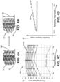
Figure 4B is a plan view of a footprint of the tire shown inFigure 1 in a worn condition with irregular wear; -
Figure 4C is a graphical representation of a wear distribution plot for a tire experiencing irregular wear; -
Figure 4D is a graphical representation of footprint centerline length versus remaining tread depth for a tire experiencing irregular wear; -
Figure 5A is a graphical representation of a wear distribution plot for a tire experiencing irregular wear at both shoulders; -
Figure 5B is a graphical representation of a wear distribution plot for a tire experiencing irregular wear at one shoulder; -
Figure 6 is a schematic diagram of aspects of an exemplary embodiment of the tire irregular wear detection system of the present invention; -
Figure 7 is a schematic diagram showing optional aspects of the analysis module of the tire irregular wear detection system shown inFigure 6 ; -
Figure 8 is a flow diagram showing use of optional inputs from additional models in the irregular wear detection system of the present invention; -
Figure 9 is a schematic diagram of the vehicle shown inFigure 1 with a representation of data or information transmission to a cloud-based server and to a user device; and -
Figure 10 is a flow diagram showing use of a peer-based comparison in the irregular wear detection system of the present invention. - Similar numerals refer to similar parts throughout the drawings.
- "ANN" or "artificial neural network" is an adaptive tool for non-linear statistical data modeling that changes its structure based on external or internal information that flows through a network during a learning phase. ANN neural networks are non-linear statistical data modeling tools used to model complex relationships between inputs and outputs or to find patterns in data.
- "Axial" and "axially" means lines or directions that are parallel to the axis of rotation of the tire.
- "CAN bus" is an abbreviation for controller area network.
- "Circumferential" means lines or directions extending along the perimeter of the surface of the annular tread perpendicular to the axial direction.
- "Cloud computing" or "cloud" means computer processing involving computing power and/or data storage that is distributed across multiple data centers, which is typically facilitated by access and communication using the Internet.
- "Equatorial center plane (CP)" means the plane perpendicular to the axis of rotation of the tire and passing through the center of the tread.
- "Footprint" means the contact patch or area of contact created by the tire tread with a flat surface as the tire rotates or rolls.
- "Lateral" means an axial direction.
- "Radial" and "radially" means directions radially toward or away from the axis of rotation of the tire.
- With reference to
Figures 1 through 9 , an exemplary embodiment of the tire irregularwear detection system 10 of the present invention is presented. The tire irregularwear detection system 10 and an accompanying method are referred herein as an "indirect" system and method. Thesystem 10 and method utilize an indirect approach to detect irregular wear of a tire and avoid issued associated with the use of sensors mounted directly to the tire tread. - With particular reference to
Figure 1 , thesystem 10 detects irregular wear on eachtire 12 supporting avehicle 14. For the purpose of convenience, thesystem 10 is described with reference to onetire 12, with the understanding that the description applies to each tire supporting thevehicle 14. In addition, while thevehicle 14 is depicted as a passenger car, the invention is not to be so restricted. The principles of the invention find application in other vehicle categories, such as commercial trucks, in which vehicles may be supported by more or fewer tires than those shown inFigure 1 . - The
tires 12 are of conventional construction, and each tire is mounted on arespective wheel 16 as known to those skilled in the art. Eachtire 12 includes a pair ofsidewalls 18 that extend to acircumferential tread 20, which wears with age from road abrasion. Aninnerliner 22 is disposed on the inner surface of thetire 12, and when the tire is mounted on thewheel 16, aninternal cavity 24 is formed, which is filled with a pressurized fluid, such as air. - A
sensor unit 26 is attached to theinnerliner 22 of eachtire 12 by means such as an adhesive, and measures certain parameters or conditions of the tire, as will be described in greater detail below. It is to be understood that thesensor unit 26 may be attached in such a manner, or to other components of thetire 12, such as on or in one of thesidewalls 18, on or in thetread 20, on thewheel 16, and/or a combination thereof. For the purpose of convenience, reference herein shall be made to mounting of thesensor unit 26 on thetire 12, with the understanding that such mounting includes all such attachment. - The
sensor unit 26 is mounted on eachtire 12 for the purpose of detecting certain real-time tire parameters, such as tire pressure 38 (Figure 6 ) andtemperature 40. For this reason, thesensor unit 26 preferably includes a pressure sensor and a temperature sensor and may be of any known configuration. - The
sensor unit 26 also optionally includes electronic memory capacity for storing identification (ID) information for eachtire 12, known as tire ID information and indicated at 42 (Figure 6 ). Alternatively,tire ID information 42 may be included in another sensor unit, or in a separate tire ID storage medium, such as a tire ID tag, which preferably is in electronic communication with thesensor unit 26. Thetire ID information 42 may include tire parameter and/or manufacturing information, which will be described in greater detail below. - Turning to
Figure 2 , thesensor unit 26 preferably also measures alength 28 of acenterline 30 of afootprint 32 of thetire 12. More particularly, as thetire 12 contacts the ground, the area of contact created by thetread 20 with the ground is known as thefootprint 32. Thecenterline 30 of thefootprint 32 corresponds to the equatorial center plane of thetire 12, which is the plane that is perpendicular to the axis of rotation of the tire and which passes through the center of thetread 20. Thesensor unit 26 thus measures thelength 28 of thecenterline 30 of thetire footprint 32, which is referred to herein as thefootprint centerline length 28. Any suitable technique for measuring thefootprint centerline length 28 may be employed by thesensor unit 26. For example, thesensor unit 26 may include a strain sensor or piezoelectric sensor that measures deformation of thetread 20 and thus indicates thefootprint centerline length 28. - It is to be understood that the pressure sensor, the temperature sensor, the tire ID capacity and/or the centerline length sensor may be incorporated into the
single sensor unit 26 or may be incorporated into multiple units. For the purpose of convenience, reference herein shall be made to asingle sensor unit 26. - It has been observed that, as the
tire 12 experiences uniform wear, thefootprint centerline length 28 decreases. For example, turning toFigure 3A , thefootprint 32 for a new tire includes afootprint centerline length 28N. When the tire experiences uniform wear, as shown inFigure 3B , thefootprint 32 for the worn tire includes afootprint centerline length 28U. Thefootprint centerline length 28U of the uniformly worn tire is shorter than thefootprint centerline length 28N of thenew tire 12. - More particularly, with additional reference to
Figure 3C , a wear distribution plot 90 for atire 12 experiencing uniform wear shows a remainingtread depth 92 versus aposition 94 across a width of thetread 20. The resultinglines 96 indicate uniform or even wear across thetread 20. As shown inFigure 3D , aplot 98 of thefootprint centerline length 28 for atire 12 experiencing uniform wear versus the remainingtread depth 92 shows that the footprint centerline length decreases as the tire wears. - It has been discovered that, when the
tire 12 experiences irregular wear, thefootprint centerline length 28 increases or shows no change. For example, turning toFigure 4A , thefootprint 32 for a new tire includes thefootprint centerline length 28N. When the tire experiences irregular wear, as shown inFigure 4B , thefootprint 32 for the worn tire includes afootprint centerline length 281. Thefootprint centerline length 281 of the irregularly worn tire is longer than or is the same as thefootprint centerline length 28N of thenew tire 12. - More particularly, with additional reference to
Figure 4C , awear distribution plot 100 for atire 12 experiencing irregular wear shows the remainingtread depth 92 versus theposition 94 across a width of thetread 20. The resultinglines 102 indicate irregular or uneven wear across thetread 20. As shown inFigure 4D , aplot 104 of thefootprint centerline length 28 for atire 12 experiencing irregular wear versus the remainingtread depth 92 shows that the footprint centerline length increases or remains the same as the tire wears. - Returning to
Figures 1 and2 , thetread 20 includes ashoulder 106 near eachrespective sidewall 18. When thetire 12 experiences uneven or irregular wear, thetread 20 wears more rapidly at one or bothshoulders 106 than at thecenterline 30.Figure 5A is awear distribution plot 108 showing irregular wear of thetread 20 at bothshoulders 106. Irregular wear of bothshoulders 106 is typically caused by uneven contact pressure of thetire 12 with the road surface, which may be due to under-inflation of the tire and/or the design of the tire.Figure 5B is awear distribution plot 110 showing irregular wear of thetread 20 at oneshoulder 106. Irregular wear of oneshoulder 106 is typically caused by excessive positive or negative camber of thetire 12, which is the vertical tilt of the tire with respect to thevehicle 14. As described above, it is beneficial to detect such irregular wear of thetire 12, as it may compromise the traction or life of the tire. - Turning now to
Figure 6 , the irregularwear detection system 10 measures thefootprint centerline length 28 of thetire 12 to detect irregular wear. More particularly, as mentioned above, thesensor unit 26 measures thefootprint centerline length 28, and may measure other tire parameters, such astire pressure 38 andtire temperature 40. Thesensor unit 26 includes transmission means 34 for sending the measured tire parameters, as well as the optionaltire ID information 42, to aprocessor 36. The transmission means 34 may include an antenna for wireless transmission or wires for wired transmission. Theprocessor 36 may be integrated into thesensor unit 26, or may be a remote processor, which may be mounted on thevehicle 14 or may be cloud-based. For the purpose of convenience, theprocessor 36 will be described as a remote processor mounted on thevehicle 14, with the understanding that the processor may alternatively be cloud-based or integrated into thesensor unit 26. - Aspects of the irregular
wear detection system 10 preferably are executed on theprocessor 36, which enables input of data from thesensor unit 26 and execution of specific analysis techniques and algorithms, to be described below, which are stored in a suitable storage medium and are also in electronic communication with the processor. - In this manner, the
sensor unit 26 measures thefootprint centerline length 28, and may measure thetire pressure 38 andtire temperature 40, and transmits these measured parameters to theprocessor 36 with the optionaltire ID information 42. When employed, thetire ID information 42 enables atire construction database 44 to be electronically accessed 46. Thetire construction database 44 stores tireconstruction data 50, which will be described in greater detail below. Thedatabase 44 is in electronic communication with theprocessor 36 and may be stored on the processor, enablingtransmission 48 of thetire construction data 50 to theprocessor 36. - The
tire ID information 42 may be correlated tospecific construction data 50 for eachtire 12, including: the tire type; tire model; size information, such as rim size, width, and outer diameter; manufacturing location; manufacturing date; a tread cap code that includes or correlates to a compound identification; a mold code that includes or correlates to a tread structure identification; a tire footprint shape factor (FSF), a mold design drop; a tire belt/breaker angle; and an overlay material. Thetire ID information 42 may also correlate to a service history or other information to identify specific features and parameters of eachtire 12, as well as mechanical characteristics of the tire, such as cornering parameters, spring rate, load-inflation relationship, and the like. - An
analysis module 52 is stored on theprocessor 36, and receives thefootprint centerline length 28, as well as thetire pressure 38 andtire temperature 40. When the optionaltire ID information 42 is employed, theanalysis module 52 also receives the tire ID information and thetire construction data 50. Theanalysis module 52 analyzes these inputs to generate a determination of irregular wear, indicated at 54. For example, theanalysis module 52 may compare measurements of thefootprint centerline length 28 from thesensor unit 26 over time. Such a comparison may be made using an analytical model, such as a linear regression model or a non-linear regression model. If thefootprint centerline length 28 remains the same or increases, thetire 12 is experiencing uneven wear. When theanalysis module 52 determines that thetire 12 is experiencing uneven wear, the analysis module generates theirregular wear determination 54. - Alternatively, with reference to
Figure 7 , theanalysis module 52 may employ anevent filter 62, adenormalization filter 64, atime filter 72, and/or aprediction model 76, which may improve the accuracy of theirregular wear determination 54. When theanalysis module 52 employs anevent filter 62, theanalysis module 52 receives the tire-based data inputs oftire pressure 38,tire temperature 40,footprint centerline length 28 and the optionaltire ID information 42. Theanalysis module 52 also optionally receives data from a vehicle-mountedcollection unit 56. The data from the vehicle-mountedcollection unit 56 preferably includesvehicle speed 58, which may be calculated from global positioning system (GPS) data or other suitable source of vehicle speed data, andinertial measurements 60 for thevehicle 14 from an accelerometer. - When the
event filter 62 is employed, it is applied to the data received from the vehicle-mountedcollection unit 56. More particularly, vehicle conditions are reviewed in the event filter, including the measuredvehicle speed 58 from GPS data and theinertial measurements 60. These measured values are compared to threshold values, including upper and lower limits. If the measured values are outside of the threshold values, thesystem 10 does not proceed, as thevehicle 14 is likely to be operating outside of normal or predictable conditions. If the measured values are within the threshold values, the measured data oftire pressure 38,tire temperature 40,footprint centerline length 28, andvehicle speed 58 may be sent to adenormalization filter 64. - When the
denormalization filter 64 is employed, it accounts for the effect ofinflation pressure 38,temperature 40 andvehicle speed 58 on thefootprint centerline length 28 of thetire 12. In thedenormalization filter 64, a pre-trained regression model is used to account for the effects ofinflation pressure 38,temperature 40 andvehicle speed 58. Regardless of the vehicle and tire operating conditions, thefootprint centerline length 28 is regressed to a pre-defined nominal condition, that is, apre-defined inflation pressure 38,temperature 40 andvehicle speed 58. - The
denormalization filter 64 generates a normalizedfootprint length 66. Because thefootprint centerline length 28 of thetire 12 may also be affected by the vehicle load, it is preferred to account for the effect of load on the normalizedfootprint length 66. To account for the effect of load on the normalizedfootprint length 66, an optional historicalfootprint measurement database 68 may be accessed. The historicalfootprint measurement database 68 is in electronic communication with theprocessor 36 and may be stored on the processor, and contains a historical log offootprint measurements 70. The normalizedfootprint length 66 is correlated to thehistorical log 70 and an average of the values is taken. - The average of the values is applied to an
optional time filter 72. When thetime filter 72 is employed, it accounts for time-scale decomposition of thetire 12. More particularly, thetime filter 72 accounts for bias due to factors or parameters that may affect thetire 12 over time, and which are not among the above-described measured parameters. The technique employed in thetime filter 72 is described in greater detail inU.S. Patent Application Publication No. 2021/0061021 . - When employed, the
time filter 72 yields a regularizedfootprint length 74 for thetire 12. In addition, when theanalysis module 52 employs theevent filter 62, thedenormalization filter 64, and/or thetime filter 72, the regularizedfootprint length 74 is input into aprediction model 76 to generate theirregular wear determination 54 for thetire 12. Theprediction model 76 preferably is a non-linear regression model. By way of background, non-linear regression models are a form of regression analysis in which observational data are modeled by a function that is a nonlinear combination of the model parameters, and depends on one or more independent variables. Examples of non-linear regression models that may be employed in theprediction model 76 include a Random Forest Regressor, an XgBoost Regressor, and a CatBoost Regressor. - If the regularized
footprint length 74 remains the same or increases, theprediction model 76 determines that thetire 12 is experiencing uneven wear. When theprediction model 76 determines that thetire 12 is experiencing uneven wear, theanalysis module 52 generates theirregular wear determination 54. - Turning to
Figure 8 , in order to increase the accuracy of theirregular wear determination 54, the irregularwear detection system 10 may employ inputs from additional models. For example, the irregularwear detection system 10 may receive anadditional input 112 from a mileage-basedmodel 114. The technique employed in the mileage-basedmodel 114 is described in greater detail inU.S. Patent Application Publication No. 2018/0272813 . The mileage-basedmodel 114 indicates when thevehicle 14 has been driven for a high number of miles, which in turn provides an indication that thetire 12 has experienced wear. A comparison of theinput 112 from the mileage-basedmodel 114 and theirregular wear determination 54 from theanalysis module 52 may improve the accuracy of the irregularwear detection system 10. - The irregular
wear detection system 10 may receive anotherinput 116 from a frictional-energy model 118. The technique employed in the frictional-energy model 118 is described in greater detail inU.S. Patent No. 9,873,293 energy model 118 indicates when thevehicle 14 has accumulated high frictional energy, which in turn provides an indication that thetire 12 has experienced wear. A comparison of theinput 116 from the frictional-energy model 118 and theirregular wear determination 54 from theanalysis module 52 may improve the accuracy of the irregularwear detection system 10. - The comparison of the
irregular wear determination 54 from theanalysis module 52, theinput 112 from the mileage-basedmodel 114, and/or theinput 116 from the frictional-energy model 118 preferably is executed in acomparator 120. For example, when theirregular wear determination 54 from theanalysis module 52 exceeds a predetermined irregular wear threshold, and when theinput 112 from the mileage-basedmodel 114 exceeds a predetermined threshold, thecomparator 120 causes thesystem 10 to generate anirregular wear alert 122. Likewise, when theirregular wear determination 54 from theanalysis module 52 exceeds a predetermined irregular wear threshold, and when theinput 116 from the frictional-energy model 118 exceeds a predetermined threshold, thecomparator 120 causes thesystem 10 to generate theirregular wear alert 122. In this manner, theadditional inputs model 114 and the frictional-energy model 118, respectively, may increase the accuracy of theirregular wear determination 54 made by the irregularwear detection system 10. - Turning to
Figure 10 , as another option to increase the accuracy of theirregular wear determination 54, the irregularwear detection system 10 may employ a peer-based comparison. More particularly, whenmultiple vehicles 14 with similar platforms employsimilar tires 12 that are available for analysis, such as vehicles in afleet 124, apeer comparator 126 may be used.Similar tires 12 include tires with the same stock keeping unit (SKU) identification, the same product code, and the like. The data for each one of thesimilar tires 12, including thefootprint centerline length 28, thetire pressure 38, thetire temperature 40, and the optionaltire ID information 42, are transmitted to theprocessor 36 and theanalysis module 52 in the manner that is described above. - The
analysis module 52 analyzes the inputs as described above to generate the regularizedfootprint length 74 for eachtire 12. Theprediction model 76 includes thepeer comparator 126, which compares the regularizedfootprint lengths 74 among thetires 12 to examine trends. Because thetires 12 are similar, the same trends among the regularizedfootprint lengths 74 should occur. When ananomaly 128 occurs in the trends of the regularizedfootprint lengths 74, it is detected by thepeer comparator 126. Thepeer comparator 126 then generates a peer-baseddetermination 130, which may include an irregular wear alert. The peer-baseddetermination 130 may be more accurate in avehicle fleet 124 than an individualirregular wear determination 54. - Referring to
Figure 9 , when theirregular wear determination 54 is generated for eachtire 12, the data may be wirelessly transmitted 78 from theprocessor 36 on thevehicle 14 to a remote processor, such as a processor in a cloud-basedserver 80. Theirregular wear determination 54 may be stored and/or remotely analyzed and may also be wirelessly transmitted 82 to adisplay device 84 for a display that is accessible to a user of thevehicle 14, such as a smartphone. Alternatively, theirregular wear determination 54 may be wirelessly transmitted 86 from theprocessor 36 directly to thedisplay device 84. - As mentioned above, when the
irregular wear determination 54 exceeds a predetermined irregular wear threshold, anirregular wear alert 122 may be transmitted to thedisplay device 84. The irregularwear detection system 10 thus may provide notice to a vehicle operator that one ormore tires 12 are experiencing irregular wear. The notice may include a recommendation to check the inflation pressure of the tire, to check the alignment of thewheel 16, and/or to rotate the tires on thevehicle 14 to alleviate the irregular wear. - The irregular
wear detection system 10 may also transmit or communicate theirregular wear determination 54 and/or theirregular wear alert 122 to a service center or a fleet manager. Moreover, the irregularwear detection system 10 may transmit or communicate theirregular wear determination 54 and/or theirregular wear alert 122 to an electronic control unit of thevehicle 14 and/or a vehicle control system, such as the braking system and/or the suspension system, to increase the performance of such systems. - In this manner, the irregular
wear detection system 10 of the present invention detects irregular wear of atire 12 wear based upon thefootprint centerline length 28 of the tire. By analyzing whether thefootprint length 28 remains the same or increases as thetread 20 of thetire 12 wears, thesystem 10 accurately and reliably detects irregular wear using easily obtained and accurate parameters. The irregularwear detection system 10 of the present invention provides an independent, standalone system that does not need to be integrated into the electronic systems of thevehicle 14 to function, including the CAN bus system. - The present invention also includes a method of detecting irregular wear of a
tire 12. The method includes steps in accordance with the description that is presented above and shown inFigures 1 through 9 . - It is to be understood that the structure and method of the above-described irregular
wear detection system 10 may be altered or rearranged, or components or steps known to those skilled in the art omitted or added, without affecting the overall concept or operation of the invention. For example, electronic communication may be through a wired connection or wireless communication without affecting the overall concept or operation of the invention. Such wireless communications include radio frequency (RF) and Bluetooth® communications.
Claims (15)
- An irregular wear detection system for a tire (12) supporting a vehicle (14), the system comprising:a sensor unit (26) being mounted on the tire (12), the sensor unit including a footprint centerline length measurement sensor to measure a centerline length of a footprint (32) of the tire;a processor (36) in electronic communication with the sensor unit (26), the processor being configured for receiving a plurality of measured centerline lengths over time; andan analysis module (52) stored on the processor (36), the analysis module (52) being configured to receive the measured centerline lengths as inputs and to detect irregular wear of the tire (12) from the measured footprint centerline lengths;the analysis module (52) being further configured to generate an irregular wear determination when the measured footprint centerline lengths remain the same or increase.
- The system of claim 1, further comprising a comparator (120), the comparator (120) being configured for receiving the irregular wear determination and inputs from at least one additional model, the at least one additional model preferably including a mileage-based model (114) and/or a frictional-energy model (118).
- The system of claim 1 or 2, wherein the processor (36) includes transmission means (34) to transmit the irregular wear determination to at least one of a display device (84), a service center, a fleet manager and a vehicle control system.
- The system of at least one of the previous claims, wherein the processor (36) includes transmission means (34) to transmit a recommendation, the recommendation including at least one of checking the inflation pressure of the tire (12), checking the alignment of a wheel (16), and rotating a plurality of tires (12) on the vehicle (14).
- The system of at least one of the previous claims, wherein the analysis module (52) further comprises a denormalization filter (64) configured to receive the measured centerline length, a measured pressure of the tire, a measured temperature of the tire, identification information for the tire, and tire construction data as inputs, and to generate a normalized footprint length.
- The system of claim 5, wherein the analysis module (52) further comprises a historical footprint measurement database (68) for storing a historical log of footprint measurements, the historical footprint measurement database being in electronic communication with the processor (36), wherein the normalized footprint length is correlated to the historical log of footprint measurements, and an average of the values is taken, and, optionally, wherein the analysis module (52) further comprises a time filter (72), wherein the average of the values is applied to the time filter (72) to account for time-scale decomposition of the tire, the time filter (72) being configured to yield a regularized footprint length for the tire (12).
- The system of claim 6, wherein the analysis module (52) further comprises a prediction model (76) that is configured to receive the regularized footprint length for the tire, the prediction model (76) preferably including a non-linear regression model.
- The system of at least one of the previous claims, further comprising a vehicle-mounted collection unit to collect measurements of a speed of the vehicle (14) and an inertia of the vehicle (14), wherein the analysis module (52) is configured to receive the speed of the vehicle and the inertia of the vehicle as inputs, and wherein the analysis module (52) includes an event filter (62), wherein the speed of the vehicle and the inertia of the vehicle are compared to threshold values before further analysis is performed by the analysis module (52).
- The system of claim 8, further comprising means to calculate the speed of the vehicle (14) from global positioning system data and comprising an accelerometer for measuring the inertia of the vehicle.
- The system of at least one of the previous claims, further comprising a peer comparator (126) that is configured to detect an anomaly (128) in trends among regularized footprint lengths of a plurality of similar tires (12).
- A method for detecting irregular wear of a tire (12) supporting a vehicle (14), the method comprising the steps of:mounting a sensor unit (26) on the tire (12), the sensor unit including a footprint centerline length measurement sensor;measuring a centerline length of a footprint of the tire (12) with the footprint centerline length measurement sensor;providing a processor (36) in electronic communication with the sensor unit (26);receiving in the processor (36) a plurality of measured centerline lengths over time;
storing an analysis module (52) on the processor (36);receiving the measured centerline lengths in the analysis module (52) as inputs;detecting irregular wear of the tire (12) from the measured footprint centerline lengths; andgenerating an irregular wear determination with the analysis module (52) when the measured footprint centerline lengths remain the same or increase. - The method of claim 11, further comprising the steps of:providing a comparator (120); andreceiving in the comparator (120) the irregular wear determination and inputs from at least one additional model; and, optionally,wherein the step of receiving in the comparator (120) the irregular wear determination and inputs from at least one additional model includes receiving inputs from at least one of a mileage-based model (114) and a frictional-energy model (116).
- The method of claim 11 or 12, further comprising the steps of:providing a denormalization filter (64) in the analysis module (52);receiving the measured centerline length, a measured tire pressure, a measured tire temperature, identification information for the tire, and tire construction data as inputs in the denormalization filter (64);generating a normalized footprint length with the denormalization filter (64);storing a historical log of footprint measurements on a historical footprint measurement database being in electronic communication with the processor (36); andcorrelating the normalized footprint length to the historical log of footprint measurements, and taking an average of the values.
- The method of claim of claim 13, further comprising the steps of:providing a time filter (72) in the analysis module (52);applying the average of the values to the time filter (72) to yield a regularized footprint length for the tire (12); andinputting the regularized footprint length into a prediction model.
- The method of at least one of the claims 11 to 14, further comprising the steps of:providing a vehicle-mounted collection unit to collect measurements of a speed of the vehicle (14) and an inertia of the vehicle (14);receiving the speed of the vehicle and the inertia of the vehicle as inputs into the analysis module (52);providing an event filter (62) in the analysis module (52); andcomparing the speed of the vehicle and the inertia of the vehicle to threshold values with the event filter (62) before performing further analysis with the analysis module (52).
Applications Claiming Priority (2)
| Application Number | Priority Date | Filing Date | Title |
|---|---|---|---|
| US202163286131P | 2021-12-06 | 2021-12-06 | |
| US18/053,786 US12263704B2 (en) | 2021-12-06 | 2022-11-09 | Tire irregular wear detection system and method |
Publications (2)
| Publication Number | Publication Date |
|---|---|
| EP4190596A1 true EP4190596A1 (en) | 2023-06-07 |
| EP4190596B1 EP4190596B1 (en) | 2024-12-18 |
Family
ID=84363105
Family Applications (1)
| Application Number | Title | Priority Date | Filing Date |
|---|---|---|---|
| EP22209726.3A Active EP4190596B1 (en) | 2021-12-06 | 2022-11-25 | Tire irregular wear detection system and method |
Country Status (2)
| Country | Link |
|---|---|
| US (1) | US12263704B2 (en) |
| EP (1) | EP4190596B1 (en) |
Cited By (1)
| Publication number | Priority date | Publication date | Assignee | Title |
|---|---|---|---|---|
| CN117097765A (en) * | 2023-10-18 | 2023-11-21 | 深圳联鹏高远智能科技有限公司 | Automobile tire safety management method, system and medium based on Internet of things |
Families Citing this family (3)
| Publication number | Priority date | Publication date | Assignee | Title |
|---|---|---|---|---|
| KR102829559B1 (en) * | 2020-12-16 | 2025-07-04 | 현대자동차주식회사 | Method and apparatus for prdicting tire wear using machine learning |
| JP7697339B2 (en) * | 2021-10-01 | 2025-06-24 | 住友ゴム工業株式会社 | TIRE ABNORMALITY DETECTION SYSTEM, TIRE ABNORMALITY DETECTION DEVICE, TIRE ABNORMALITY DETECTION METHOD, AND PROGRAM |
| US20260166923A1 (en) | 2024-12-16 | 2026-06-18 | The Goodyear Tire & Rubber Company | System for estimation of mileage on a tire |
Citations (9)
| Publication number | Priority date | Publication date | Assignee | Title |
|---|---|---|---|---|
| US20060201240A1 (en) * | 2003-08-19 | 2006-09-14 | Kabushiki Kaisha Bridgestone | Sensor-incorporated tire and tire condition estimating method |
| US20060208902A1 (en) * | 2005-03-11 | 2006-09-21 | Brey Thomas A | Tire tread wear sensor system |
| JP2011168211A (en) * | 2010-02-19 | 2011-09-01 | Bridgestone Corp | Estimating method of tire partial wear |
| JP2013136297A (en) * | 2011-12-28 | 2013-07-11 | Bridgestone Corp | Method and device for detecting uneven wear of tire |
| EP2857227A1 (en) * | 2012-05-24 | 2015-04-08 | Bridgestone Corporation | Method for detecting uneven wear on tire and device for detecting uneven wear on tire |
| US9873293B2 (en) | 2015-10-21 | 2018-01-23 | The Goodyear Tire & Rubber Company | Indirect tire wear state prediction system and method |
| US20180272813A1 (en) | 2017-03-23 | 2018-09-27 | The Goodyear Tire & Rubber Company | Model based tire wear estimation system and method |
| EP3785944A1 (en) * | 2019-08-30 | 2021-03-03 | The Goodyear Tire & Rubber Company | Tire wear state estimation system and method employing footprint shape factor |
| US20210061021A1 (en) | 2019-08-30 | 2021-03-04 | The Goodyear Tire & Rubber Company | Method for extracting changes in tire characteristics |
Family Cites Families (104)
| Publication number | Priority date | Publication date | Assignee | Title |
|---|---|---|---|---|
| US4364267A (en) * | 1980-08-20 | 1982-12-21 | The Goodyear Tire & Rubber Company | Method and apparatus for correlating tire inflation pressure and load |
| US5749984A (en) | 1995-12-29 | 1998-05-12 | Michelin Recherche Et Technique S.A. | Tire monitoring system and method |
| US5864056A (en) | 1998-02-17 | 1999-01-26 | Bell; Larry D. | Method and apparatus for monitoring the coefficient of friction between a tire and rolling surface, particularly to provide the vehicle operator with coefficient of friction, tire tread wear out and skid warning indications |
| US6083268A (en) | 1998-04-27 | 2000-07-04 | Bridgestone/Firestone, Inc. | Method for designing pneumatic tires for rolling conditions |
| EP1489532A3 (en) | 1998-09-07 | 2006-03-08 | Bridgestone Corporation | Method of estimating tire performance |
| DE19908701B4 (en) | 1999-02-26 | 2005-04-14 | Continental Teves Ag & Co. Ohg | Method and device for determining the run-flat condition of a pneumatic tire |
| US7267148B2 (en) | 1999-08-10 | 2007-09-11 | Michelin Recherche Et Technique S.A. | Measurement of adherence between a vehicle wheel and the roadway |
| JP4357074B2 (en) | 2000-03-17 | 2009-11-04 | 株式会社ブリヂストン | Tire wear prediction method and tire wear prediction apparatus |
| US6532812B2 (en) | 2001-04-23 | 2003-03-18 | Ambient, Inc. | Method for improving vehicle tire tread wear |
| DE10218781A1 (en) | 2002-04-26 | 2003-11-13 | Tuev Automotive Gmbh | Pneumatic tire mountable on a rim, sensor network, revolution measuring unit and vehicle monitoring system |
| FR2841827A1 (en) | 2002-07-04 | 2004-01-09 | Michelin Soc Tech | ESTIMATING THE WEAR OF A TIRE |
| JP4812624B2 (en) | 2004-06-23 | 2011-11-09 | 株式会社ブリヂストン | Tire wear detection system and pneumatic tire |
| GB0415258D0 (en) | 2004-07-07 | 2004-08-11 | Wheelright Ltd | Vehicle tyre checking system |
| KR100811993B1 (en) | 2004-11-03 | 2008-03-10 | 주식회사 현대오토넷 | Tire Life Prediction Apparatus and Method |
| US7114383B2 (en) | 2005-01-07 | 2006-10-03 | Bridgestone Firestone North American Tire, Llc | Method and apparatus for monitoring tire performance |
| JP3853344B2 (en) | 2005-02-23 | 2006-12-06 | 横浜ゴム株式会社 | Tire wear prediction method, tire design method, tire manufacturing method, tire wear prediction system and program |
| CN101183402B (en) | 2006-11-13 | 2012-07-25 | 韩国轮胎株式会社 | Actual abrasion wear prediction method for tyre tread |
| JP5111505B2 (en) | 2007-07-11 | 2013-01-09 | 株式会社ブリヂストン | Tire wear estimation method |
| US7543491B2 (en) | 2007-09-19 | 2009-06-09 | Infineon Technologies Ag | Capacitive measurement of tire deformation |
| US7523656B1 (en) | 2007-11-01 | 2009-04-28 | Infineon Technologies Ag | Tire sensor system and monitoring method |
| DE102008006566A1 (en) | 2008-01-29 | 2009-07-30 | Robert Bosch Gmbh | Method for determining a vehicle tire tread depth |
| US7755367B2 (en) | 2008-06-02 | 2010-07-13 | Infineon Technologies, Ag | Silicon MEMS resonators |
| US8096172B2 (en) | 2008-06-03 | 2012-01-17 | Infineon Technologies Ag | Wireless communication apparatuses, systems and methods |
| EP2301769B1 (en) | 2008-06-25 | 2017-01-11 | Kabushiki Kaisha Bridgestone | Method for estimating tire wear and device for estimating tire wear |
| US7673505B2 (en) | 2008-08-01 | 2010-03-09 | Infineon Technologies Ag | Tire footprint determination apparatuses, systems and methods |
| DE102008049047A1 (en) | 2008-09-26 | 2010-04-15 | Continental Automotive Gmbh | Method and monitoring unit for monitoring a tire of a vehicle |
| IT1393071B1 (en) | 2008-10-24 | 2012-04-11 | Pirelli | METHOD AND SYSTEM FOR WEAR TESTING OF THE VEHICLE TIRES |
| FR2937902B1 (en) | 2008-11-06 | 2011-12-09 | Michelin Rech Tech | PNEUMATIC WITH SOUND WITNESSES |
| FR2940190B1 (en) | 2008-12-23 | 2012-05-18 | Michelin Soc Tech | ALERT METHOD FOR WEARING A PNEUMATIC WITH A SILL |
| DE102009006458A1 (en) | 2009-01-28 | 2010-08-05 | Continental Automotive Gmbh | Device and method for measuring the tread depth of a motor vehicle tire |
| JP5261321B2 (en) | 2009-08-25 | 2013-08-14 | 株式会社ブリヂストン | Tire index calculation method, apparatus, and program |
| FR2953164B1 (en) | 2009-12-02 | 2012-01-06 | Michelin Soc Tech | METHOD OF DETECTING THE WEAR OF A TIRE |
| DE102009057596A1 (en) | 2009-12-09 | 2011-06-16 | Continental Aktiengesellschaft | Device for determining a latitudinal length of a vehicle tire |
| FR2954225B1 (en) | 2009-12-18 | 2012-05-11 | Michelin Soc Tech | PNEUMATIC HAVING MULTINIVEAL WEAR WITNESSES |
| JP5534588B2 (en) | 2010-02-24 | 2014-07-02 | 株式会社ブリヂストン | Tire rubber index calculation method, apparatus and program |
| BR112013014724A2 (en) | 2010-12-23 | 2016-10-04 | Pirelli | method and system for estimating the load acting on a tire |
| CN103347712B (en) | 2010-12-30 | 2015-11-25 | 米其林集团总公司 | For determining the system and method based on piezoelectricity of loading of tire |
| US8555698B2 (en) | 2011-01-26 | 2013-10-15 | Bridgestone Americas Tire Operations, Llc | Engineered surfaces for laboratory tread wear testing of tires |
| FR2981009B1 (en) | 2011-10-06 | 2013-12-20 | Michelin Soc Tech | IMPROVED METHOD OF DETECTING THE WEAR OF A TIRE |
| JP5898519B2 (en) | 2012-02-17 | 2016-04-06 | 株式会社ブリヂストン | Tire wear amount estimation method and tire wear amount estimation device |
| WO2013145204A1 (en) | 2012-03-29 | 2013-10-03 | コンパニー ゼネラール デ エタブリッスマン ミシュラン | Tread for pneumatic tire |
| US9290045B2 (en) * | 2012-04-05 | 2016-03-22 | Compagnie Generale Des Etablissements Michelin | Spoke for a tire with optimized thickness for improved durability |
| WO2013153088A1 (en) | 2012-04-11 | 2013-10-17 | Huf Hülsbeck & Fürst Gmbh & Co. Kg | Tyre module with piezo‑electric transducer and tyre equipped therewith |
| DE102012212934A1 (en) | 2012-07-24 | 2014-06-12 | Continental Automotive Gmbh | Method and device for estimating a tread depth of a tire |
| JP5347054B1 (en) | 2012-09-03 | 2013-11-20 | 株式会社ブリヂストン | Tire case life prediction system |
| DE102012217901B3 (en) | 2012-10-01 | 2014-05-28 | Continental Automotive Gmbh | Method, controller and system for determining a tread depth of a tread of a tire |
| US10024765B2 (en) | 2012-10-31 | 2018-07-17 | Compagnie Generale Des Etablissements Michelin | System and method for analyzing tire tread parameters |
| DE102013208553A1 (en) | 2013-05-08 | 2014-11-13 | Fachhochschule Brandenburg | Method and device for detecting conditions in tires |
| US9259976B2 (en) | 2013-08-12 | 2016-02-16 | The Goodyear Tire & Rubber Company | Torsional mode tire wear state estimation system and method |
| DE102013220882B4 (en) | 2013-10-15 | 2019-05-29 | Continental Automotive Gmbh | Method, control unit and system for determining a tread depth of a profile of at least one tire |
| JP6227385B2 (en) | 2013-11-21 | 2017-11-08 | Ntn株式会社 | Wear detection device for automobile tires |
| JP5806278B2 (en) | 2013-11-26 | 2015-11-10 | 株式会社ブリヂストン | Tire uneven wear estimation method and tire uneven wear estimation apparatus |
| FR3014366B1 (en) | 2013-12-05 | 2016-01-08 | Continental Automotive France | METHOD FOR DETERMINING THE IMPRESSION OF A WHEEL TIRE ON THE GROUND |
| FR3020019B1 (en) | 2014-04-18 | 2017-12-08 | Continental Automotive France | METHOD AND EQUIPMENT FOR MONITORING PNEUMATIC WEAR AND VEHICLE WEAR FOLLOWING SYSTEM |
| FR3020680B1 (en) | 2014-05-02 | 2017-11-24 | Michelin & Cie | SYSTEM FOR EVALUATING THE CONDITION OF A TIRE |
| MX2016017148A (en) | 2014-06-19 | 2017-05-03 | Neomatix Ltd | System and method for multiple feature detection and analysis of a rotating tire. |
| JP6291366B2 (en) | 2014-06-25 | 2018-03-14 | 住友ゴム工業株式会社 | Tire simulation method and simulation apparatus |
| DE102014110183A1 (en) | 2014-07-18 | 2016-01-21 | Infineon Technologies Ag | Pressure sensitive film, tire pressure sensor module, tire, method and computer program for obtaining information related to the deformations of a tire |
| DE102014214626A1 (en) | 2014-07-25 | 2016-01-28 | Robert Bosch Gmbh | Method for determining the state of wear of at least one tire of a motor vehicle |
| US9921134B2 (en) | 2014-08-04 | 2018-03-20 | Dr. Ing. H.C. F. Porsche Aktiengesellschaft | System and method for determining tire wear |
| US10245906B2 (en) * | 2014-11-11 | 2019-04-02 | The Goodyear Tire & Rubber Company | Tire wear compensated load estimation system and method |
| US9963146B2 (en) | 2014-12-03 | 2018-05-08 | The Goodyear Tire & Rubber Company | Tire lift-off propensity predictive system and method |
| FR3030373B1 (en) | 2014-12-17 | 2018-03-23 | Continental Automotive France | METHOD FOR ESTIMATING THE RELIABILITY OF WHEEL SENSOR MEASUREMENTS OF A VEHICLE AND SYSTEM FOR IMPLEMENTING SAID METHOD |
| DE102014226783B4 (en) | 2014-12-22 | 2020-01-02 | Continental Automotive Gmbh | System and method for determining at least one tire tire parameter characterizing a dimension of a tire patch on a tire of a wheel of a vehicle |
| JP6455181B2 (en) | 2015-01-28 | 2019-01-23 | 横浜ゴム株式会社 | Tire wear evaluation method |
| JP6650680B2 (en) | 2015-03-31 | 2020-02-19 | 株式会社ブリヂストン | Tire wear estimation method and tire wear estimation device |
| US10082381B2 (en) | 2015-04-30 | 2018-09-25 | Bebop Sensors, Inc. | Sensor systems integrated with vehicle tires |
| IN2015CH02899A (en) | 2015-06-10 | 2015-06-19 | Tymtix Technologies Pvt Ltd | |
| US9994082B2 (en) | 2015-07-31 | 2018-06-12 | Texas Instruments Deutschland, Gmbh | Tire monitoring based on inductive sensing |
| KR102626289B1 (en) | 2015-08-14 | 2024-02-02 | 코다 이노베이션스 | Tire condition or vehicle monitoring system and method |
| DE102015216212A1 (en) | 2015-08-25 | 2017-03-02 | Continental Reifen Deutschland Gmbh | Method for determining a tread depth of a tire profile, and control device therefor |
| DE102015216210A1 (en) | 2015-08-25 | 2017-03-02 | Continental Reifen Deutschland Gmbh | Method for determining tire characteristic influencing variables, and control device therefor |
| KR101741730B1 (en) | 2015-12-30 | 2017-06-16 | 만도헬라일렉트로닉스(주) | Tire Monitoring System in a vehicle and method thereof |
| CN108712972A (en) | 2016-03-09 | 2018-10-26 | 米其林集团总公司 | Vehicle Integrated Expected Tread Life Indication System |
| JP2017161477A (en) | 2016-03-11 | 2017-09-14 | 株式会社ブリヂストン | Tire load estimation method and tire load estimation device |
| CN106248401A (en) | 2016-08-30 | 2016-12-21 | 万通智控科技股份有限公司 | A kind of electronic module and vehicle tyre wear detecting system |
| DE102016116698B3 (en) | 2016-09-07 | 2017-12-07 | Infineon Technologies Ag | A failsafe device, a tire pressure measurement system, a vehicle, a method of monitoring, and a computer program |
| DE102016116696A1 (en) | 2016-09-07 | 2018-03-08 | Infineon Technologies Ag | An apparatus, a tire pressure measurement system, a tire, a vehicle, a method, and a computer program for determining information indicative of a length of a tire footprint of a tire |
| EP3318422B1 (en) | 2016-11-08 | 2019-08-28 | The Goodyear Tire & Rubber Company | Indirect tire wear state prediction system and method |
| US20180154707A1 (en) | 2016-12-05 | 2018-06-07 | The Goodyear Tire & Rubber Company | Indirect tire pressure and wear state estimation system and method |
| US10809742B2 (en) | 2017-03-06 | 2020-10-20 | The Goodyear Tire & Rubber Company | System and method for tire sensor-based autonomous vehicle fleet management |
| DE102017204648A1 (en) | 2017-03-21 | 2018-09-27 | Continental Automotive Gmbh | Method, control device and system for determining a tread depth of a profile of a tire |
| FR3067137A1 (en) | 2017-06-02 | 2018-12-07 | Compagnie Generale Des Etablissements Michelin | METHOD FOR PROVIDING A SERVICE RELATED TO THE STATE AND / OR BEHAVIOR OF A VEHICLE AND / OR A TIRE |
| US10603962B2 (en) | 2017-06-29 | 2020-03-31 | The Goodyear Tire & Rubber Company | Tire wear state estimation system and method |
| DE102017221142B4 (en) | 2017-11-27 | 2019-12-19 | Continental Automotive Gmbh | Method, control device and system for determining a tread depth of a tread profile |
| US11090984B2 (en) | 2017-12-20 | 2021-08-17 | The Goodyear Tire & Rubber Company | Sensor system for monitoring tire wear |
| US20190193479A1 (en) | 2017-12-20 | 2019-06-27 | The Goodyear Tire & Rubber Company | Sensor system for monitoring tire wear |
| US10518590B2 (en) | 2018-03-05 | 2019-12-31 | Sensata Technologies, Inc. | System and method for tracking tire tread wear |
| IT201800003994A1 (en) | 2018-03-27 | 2019-09-27 | Bridgestone Europe Nv Sa | TREAD FOR TIRE AND PNEUMATIC |
| US10997708B2 (en) | 2018-04-03 | 2021-05-04 | GM Global Technology Operations LLC | Quantifying tread rib edge locations |
| US20190382034A1 (en) | 2018-06-13 | 2019-12-19 | GM Global Technology Operations LLC | Systems and methods for active tire performance monitoring |
| IT201800006322A1 (en) | 2018-06-14 | 2019-12-14 | SYSTEM AND METHOD FOR MONITORING THE CONSUMPTION OF TREAD | |
| US10960712B2 (en) | 2018-06-28 | 2021-03-30 | Nissan North America, Inc. | Tire wear estimation using a hybrid machine learning system and method |
| CN110733299A (en) | 2018-07-18 | 2020-01-31 | 住友橡胶工业株式会社 | Tire assembly, monitoring system and method of tire |
| KR102127662B1 (en) | 2018-07-25 | 2020-06-29 | 한국타이어앤테크놀로지 주식회사 | Multi-position system sensors for tires and tires having the sensor |
| US20200047571A1 (en) | 2018-08-10 | 2020-02-13 | GM Global Technology Operations LLC | Groove wander calculations from tire-road contact details |
| US10875539B2 (en) | 2018-08-22 | 2020-12-29 | Infineon Technologies Ag | Tire load estimation |
| US10960714B2 (en) | 2018-09-26 | 2021-03-30 | The Goodyear Tire & Rubber Company | Tire with printed shear sensors |
| EP3861288B1 (en) | 2018-10-02 | 2025-03-26 | Pirelli Tyre S.p.A. | Method and system for estimating a residual range of a vehicle |
| CN109472885B (en) | 2018-11-14 | 2021-09-03 | 广州小鹏汽车科技有限公司 | Tire safety management method and device, tire safety management equipment and automobile |
| US11644386B2 (en) | 2018-12-11 | 2023-05-09 | The Goodyear Tire & Rubber Company | Tire wear state estimation system and method |
| JP7329068B2 (en) * | 2019-04-01 | 2023-08-17 | ブリヂストン アメリカズ タイヤ オペレーションズ、 エルエルシー | Systems and methods for vehicle tire performance modeling and feedback |
| AU2020220054A1 (en) * | 2019-08-30 | 2021-03-18 | The Goodyear Tire & Rubber Company | Tire wear state estimation system and method employing footprint length |
| KR102255677B1 (en) * | 2019-10-02 | 2021-05-27 | 한국타이어앤테크놀로지 주식회사 | Tire wear measurement device using acceleration peak value of tire and tire wear measurement method using same |
-
2022
- 2022-11-09 US US18/053,786 patent/US12263704B2/en active Active
- 2022-11-25 EP EP22209726.3A patent/EP4190596B1/en active Active
Patent Citations (9)
| Publication number | Priority date | Publication date | Assignee | Title |
|---|---|---|---|---|
| US20060201240A1 (en) * | 2003-08-19 | 2006-09-14 | Kabushiki Kaisha Bridgestone | Sensor-incorporated tire and tire condition estimating method |
| US20060208902A1 (en) * | 2005-03-11 | 2006-09-21 | Brey Thomas A | Tire tread wear sensor system |
| JP2011168211A (en) * | 2010-02-19 | 2011-09-01 | Bridgestone Corp | Estimating method of tire partial wear |
| JP2013136297A (en) * | 2011-12-28 | 2013-07-11 | Bridgestone Corp | Method and device for detecting uneven wear of tire |
| EP2857227A1 (en) * | 2012-05-24 | 2015-04-08 | Bridgestone Corporation | Method for detecting uneven wear on tire and device for detecting uneven wear on tire |
| US9873293B2 (en) | 2015-10-21 | 2018-01-23 | The Goodyear Tire & Rubber Company | Indirect tire wear state prediction system and method |
| US20180272813A1 (en) | 2017-03-23 | 2018-09-27 | The Goodyear Tire & Rubber Company | Model based tire wear estimation system and method |
| EP3785944A1 (en) * | 2019-08-30 | 2021-03-03 | The Goodyear Tire & Rubber Company | Tire wear state estimation system and method employing footprint shape factor |
| US20210061021A1 (en) | 2019-08-30 | 2021-03-04 | The Goodyear Tire & Rubber Company | Method for extracting changes in tire characteristics |
Cited By (2)
| Publication number | Priority date | Publication date | Assignee | Title |
|---|---|---|---|---|
| CN117097765A (en) * | 2023-10-18 | 2023-11-21 | 深圳联鹏高远智能科技有限公司 | Automobile tire safety management method, system and medium based on Internet of things |
| CN117097765B (en) * | 2023-10-18 | 2024-02-06 | 深圳联鹏高远智能科技有限公司 | Automobile tire safety management method, system and medium based on Internet of things |
Also Published As
| Publication number | Publication date |
|---|---|
| EP4190596B1 (en) | 2024-12-18 |
| US20230173852A1 (en) | 2023-06-08 |
| US12263704B2 (en) | 2025-04-01 |
Similar Documents
| Publication | Publication Date | Title |
|---|---|---|
| US11548324B2 (en) | Tire wear state estimation system and method employing footprint length | |
| EP4190596B1 (en) | Tire irregular wear detection system and method | |
| US11981163B2 (en) | Tire wear state estimation system and method employing footprint shape factor | |
| EP3838628B1 (en) | Method of estimating tire conditions | |
| EP4029707A1 (en) | System and method for auto-location of tires | |
| US11644386B2 (en) | Tire wear state estimation system and method | |
| EP3858690B1 (en) | Method for estimating tire grip | |
| EP3785942B1 (en) | Method for extracting changes in tire characteristics | |
| EP3957501B1 (en) | Tire high temperature forecasting system and method | |
| EP4112335A1 (en) | Tire pressure monitoring system and method employing axle cross comparison | |
| CN112976956A (en) | Method for evaluating the condition of a tyre | |
| EP4101659B1 (en) | Tire replacement forecasting system and method | |
| EP4385767B1 (en) | System and method for auto-location of tires employing footprint length | |
| US12344049B2 (en) | System for auto-location of tires employing footprint length | |
| EP4151436A1 (en) | Counter-deflection load estimation system and method | |
| CN118024792A (en) | Method and system for monitoring tire inflation pressure | |
| CN118182021A (en) | System for automatically positioning tire by utilizing print length |
Legal Events
| Date | Code | Title | Description |
|---|---|---|---|
| PUAI | Public reference made under article 153(3) epc to a published international application that has entered the european phase |
Free format text: ORIGINAL CODE: 0009012 |
|
| STAA | Information on the status of an ep patent application or granted ep patent |
Free format text: STATUS: THE APPLICATION HAS BEEN PUBLISHED |
|
| AK | Designated contracting states |
Kind code of ref document: A1 Designated state(s): AL AT BE BG CH CY CZ DE DK EE ES FI FR GB GR HR HU IE IS IT LI LT LU LV MC ME MK MT NL NO PL PT RO RS SE SI SK SM TR |
|
| STAA | Information on the status of an ep patent application or granted ep patent |
Free format text: STATUS: REQUEST FOR EXAMINATION WAS MADE |
|
| 17P | Request for examination filed |
Effective date: 20231207 |
|
| RBV | Designated contracting states (corrected) |
Designated state(s): AL AT BE BG CH CY CZ DE DK EE ES FI FR GB GR HR HU IE IS IT LI LT LU LV MC ME MK MT NL NO PL PT RO RS SE SI SK SM TR |
|
| GRAP | Despatch of communication of intention to grant a patent |
Free format text: ORIGINAL CODE: EPIDOSNIGR1 |
|
| STAA | Information on the status of an ep patent application or granted ep patent |
Free format text: STATUS: GRANT OF PATENT IS INTENDED |
|
| RIC1 | Information provided on ipc code assigned before grant |
Ipc: B60C 11/24 20060101AFI20240613BHEP |
|
| INTG | Intention to grant announced |
Effective date: 20240712 |
|
| GRAS | Grant fee paid |
Free format text: ORIGINAL CODE: EPIDOSNIGR3 |
|
| GRAA | (expected) grant |
Free format text: ORIGINAL CODE: 0009210 |
|
| STAA | Information on the status of an ep patent application or granted ep patent |
Free format text: STATUS: THE PATENT HAS BEEN GRANTED |
|
| AK | Designated contracting states |
Kind code of ref document: B1 Designated state(s): AL AT BE BG CH CY CZ DE DK EE ES FI FR GB GR HR HU IE IS IT LI LT LU LV MC ME MK MT NL NO PL PT RO RS SE SI SK SM TR |
|
| REG | Reference to a national code |
Ref country code: CH Ref legal event code: EP |
|
| REG | Reference to a national code |
Ref country code: DE Ref legal event code: R096 Ref document number: 602022008815 Country of ref document: DE |
|
| REG | Reference to a national code |
Ref country code: IE Ref legal event code: FG4D |
|
| REG | Reference to a national code |
Ref country code: LT Ref legal event code: MG9D |
|
| PG25 | Lapsed in a contracting state [announced via postgrant information from national office to epo] |
Ref country code: HR Free format text: LAPSE BECAUSE OF FAILURE TO SUBMIT A TRANSLATION OF THE DESCRIPTION OR TO PAY THE FEE WITHIN THE PRESCRIBED TIME-LIMIT Effective date: 20241218 |
|
| PG25 | Lapsed in a contracting state [announced via postgrant information from national office to epo] |
Ref country code: FI Free format text: LAPSE BECAUSE OF FAILURE TO SUBMIT A TRANSLATION OF THE DESCRIPTION OR TO PAY THE FEE WITHIN THE PRESCRIBED TIME-LIMIT Effective date: 20241218 |
|
| PG25 | Lapsed in a contracting state [announced via postgrant information from national office to epo] |
Ref country code: BG Free format text: LAPSE BECAUSE OF FAILURE TO SUBMIT A TRANSLATION OF THE DESCRIPTION OR TO PAY THE FEE WITHIN THE PRESCRIBED TIME-LIMIT Effective date: 20241218 |
|
| PG25 | Lapsed in a contracting state [announced via postgrant information from national office to epo] |
Ref country code: NO Free format text: LAPSE BECAUSE OF FAILURE TO SUBMIT A TRANSLATION OF THE DESCRIPTION OR TO PAY THE FEE WITHIN THE PRESCRIBED TIME-LIMIT Effective date: 20250318 |
|
| REG | Reference to a national code |
Ref country code: NL Ref legal event code: MP Effective date: 20241218 |
|
| PG25 | Lapsed in a contracting state [announced via postgrant information from national office to epo] |
Ref country code: LV Free format text: LAPSE BECAUSE OF FAILURE TO SUBMIT A TRANSLATION OF THE DESCRIPTION OR TO PAY THE FEE WITHIN THE PRESCRIBED TIME-LIMIT Effective date: 20241218 Ref country code: GR Free format text: LAPSE BECAUSE OF FAILURE TO SUBMIT A TRANSLATION OF THE DESCRIPTION OR TO PAY THE FEE WITHIN THE PRESCRIBED TIME-LIMIT Effective date: 20250319 |
|
| PG25 | Lapsed in a contracting state [announced via postgrant information from national office to epo] |
Ref country code: RS Free format text: LAPSE BECAUSE OF FAILURE TO SUBMIT A TRANSLATION OF THE DESCRIPTION OR TO PAY THE FEE WITHIN THE PRESCRIBED TIME-LIMIT Effective date: 20250318 |
|
| PG25 | Lapsed in a contracting state [announced via postgrant information from national office to epo] |
Ref country code: NL Free format text: LAPSE BECAUSE OF FAILURE TO SUBMIT A TRANSLATION OF THE DESCRIPTION OR TO PAY THE FEE WITHIN THE PRESCRIBED TIME-LIMIT Effective date: 20241218 |
|
| REG | Reference to a national code |
Ref country code: AT Ref legal event code: MK05 Ref document number: 1751987 Country of ref document: AT Kind code of ref document: T Effective date: 20241218 |
|
| PG25 | Lapsed in a contracting state [announced via postgrant information from national office to epo] |
Ref country code: SM Free format text: LAPSE BECAUSE OF FAILURE TO SUBMIT A TRANSLATION OF THE DESCRIPTION OR TO PAY THE FEE WITHIN THE PRESCRIBED TIME-LIMIT Effective date: 20241218 |
|
| PG25 | Lapsed in a contracting state [announced via postgrant information from national office to epo] |
Ref country code: PL Free format text: LAPSE BECAUSE OF FAILURE TO SUBMIT A TRANSLATION OF THE DESCRIPTION OR TO PAY THE FEE WITHIN THE PRESCRIBED TIME-LIMIT Effective date: 20241218 |
|
| PG25 | Lapsed in a contracting state [announced via postgrant information from national office to epo] |
Ref country code: ES Free format text: LAPSE BECAUSE OF FAILURE TO SUBMIT A TRANSLATION OF THE DESCRIPTION OR TO PAY THE FEE WITHIN THE PRESCRIBED TIME-LIMIT Effective date: 20241218 |
|
| PG25 | Lapsed in a contracting state [announced via postgrant information from national office to epo] |
Ref country code: IS Free format text: LAPSE BECAUSE OF FAILURE TO SUBMIT A TRANSLATION OF THE DESCRIPTION OR TO PAY THE FEE WITHIN THE PRESCRIBED TIME-LIMIT Effective date: 20250418 |
|
| PG25 | Lapsed in a contracting state [announced via postgrant information from national office to epo] |
Ref country code: PT Free format text: LAPSE BECAUSE OF FAILURE TO SUBMIT A TRANSLATION OF THE DESCRIPTION OR TO PAY THE FEE WITHIN THE PRESCRIBED TIME-LIMIT Effective date: 20250421 |
|
| PG25 | Lapsed in a contracting state [announced via postgrant information from national office to epo] |
Ref country code: EE Free format text: LAPSE BECAUSE OF FAILURE TO SUBMIT A TRANSLATION OF THE DESCRIPTION OR TO PAY THE FEE WITHIN THE PRESCRIBED TIME-LIMIT Effective date: 20241218 |
|
| PG25 | Lapsed in a contracting state [announced via postgrant information from national office to epo] |
Ref country code: AT Free format text: LAPSE BECAUSE OF FAILURE TO SUBMIT A TRANSLATION OF THE DESCRIPTION OR TO PAY THE FEE WITHIN THE PRESCRIBED TIME-LIMIT Effective date: 20241218 Ref country code: RO Free format text: LAPSE BECAUSE OF FAILURE TO SUBMIT A TRANSLATION OF THE DESCRIPTION OR TO PAY THE FEE WITHIN THE PRESCRIBED TIME-LIMIT Effective date: 20241218 |
|
| PG25 | Lapsed in a contracting state [announced via postgrant information from national office to epo] |
Ref country code: SK Free format text: LAPSE BECAUSE OF FAILURE TO SUBMIT A TRANSLATION OF THE DESCRIPTION OR TO PAY THE FEE WITHIN THE PRESCRIBED TIME-LIMIT Effective date: 20241218 |
|
| PG25 | Lapsed in a contracting state [announced via postgrant information from national office to epo] |
Ref country code: CZ Free format text: LAPSE BECAUSE OF FAILURE TO SUBMIT A TRANSLATION OF THE DESCRIPTION OR TO PAY THE FEE WITHIN THE PRESCRIBED TIME-LIMIT Effective date: 20241218 |
|
| PG25 | Lapsed in a contracting state [announced via postgrant information from national office to epo] |
Ref country code: SE Free format text: LAPSE BECAUSE OF FAILURE TO SUBMIT A TRANSLATION OF THE DESCRIPTION OR TO PAY THE FEE WITHIN THE PRESCRIBED TIME-LIMIT Effective date: 20241218 |
|
| REG | Reference to a national code |
Ref country code: DE Ref legal event code: R097 Ref document number: 602022008815 Country of ref document: DE |
|
| PG25 | Lapsed in a contracting state [announced via postgrant information from national office to epo] |
Ref country code: DK Free format text: LAPSE BECAUSE OF FAILURE TO SUBMIT A TRANSLATION OF THE DESCRIPTION OR TO PAY THE FEE WITHIN THE PRESCRIBED TIME-LIMIT Effective date: 20241218 |
|
| PLBE | No opposition filed within time limit |
Free format text: ORIGINAL CODE: 0009261 |
|
| STAA | Information on the status of an ep patent application or granted ep patent |
Free format text: STATUS: NO OPPOSITION FILED WITHIN TIME LIMIT |
|
| REG | Reference to a national code |
Ref country code: CH Ref legal event code: L10 Free format text: ST27 STATUS EVENT CODE: U-0-0-L10-L00 (AS PROVIDED BY THE NATIONAL OFFICE) Effective date: 20251029 |
|
| 26N | No opposition filed |
Effective date: 20250919 |
|
| PGFP | Annual fee paid to national office [announced via postgrant information from national office to epo] |
Ref country code: DE Payment date: 20251022 Year of fee payment: 4 |
|
| PGFP | Annual fee paid to national office [announced via postgrant information from national office to epo] |
Ref country code: IT Payment date: 20251201 Year of fee payment: 4 |
|
| PGFP | Annual fee paid to national office [announced via postgrant information from national office to epo] |
Ref country code: FR Payment date: 20251022 Year of fee payment: 4 |
|
| REG | Reference to a national code |
Ref country code: CH Ref legal event code: H13 Free format text: ST27 STATUS EVENT CODE: U-0-0-H10-H13 (AS PROVIDED BY THE NATIONAL OFFICE) Effective date: 20260623 |
|
| PG25 | Lapsed in a contracting state [announced via postgrant information from national office to epo] |
Ref country code: LT Free format text: LAPSE BECAUSE OF FAILURE TO SUBMIT A TRANSLATION OF THE DESCRIPTION OR TO PAY THE FEE WITHIN THE PRESCRIBED TIME-LIMIT Effective date: 20241218 |
|
| PG25 | Lapsed in a contracting state [announced via postgrant information from national office to epo] |
Ref country code: MC Free format text: LAPSE BECAUSE OF FAILURE TO SUBMIT A TRANSLATION OF THE DESCRIPTION OR TO PAY THE FEE WITHIN THE PRESCRIBED TIME-LIMIT Effective date: 20241218 |
|
| PG25 | Lapsed in a contracting state [announced via postgrant information from national office to epo] |
Ref country code: LU Free format text: LAPSE BECAUSE OF NON-PAYMENT OF DUE FEES Effective date: 20251125 Ref country code: CH Free format text: LAPSE BECAUSE OF NON-PAYMENT OF DUE FEES Effective date: 20251130 |