EP4190579A1 - Heat transfer system - Google Patents
Heat transfer system Download PDFInfo
- Publication number
- EP4190579A1 EP4190579A1 EP21852360.3A EP21852360A EP4190579A1 EP 4190579 A1 EP4190579 A1 EP 4190579A1 EP 21852360 A EP21852360 A EP 21852360A EP 4190579 A1 EP4190579 A1 EP 4190579A1
- Authority
- EP
- European Patent Office
- Prior art keywords
- ink
- ink ribbon
- heating element
- layer
- transfer system
- Prior art date
- Legal status (The legal status is an assumption and is not a legal conclusion. Google has not performed a legal analysis and makes no representation as to the accuracy of the status listed.)
- Granted
Links
Images




Classifications
-
- B—PERFORMING OPERATIONS; TRANSPORTING
- B41—PRINTING; LINING MACHINES; TYPEWRITERS; STAMPS
- B41J—TYPEWRITERS; SELECTIVE PRINTING MECHANISMS, i.e. MECHANISMS PRINTING OTHERWISE THAN FROM A FORME; CORRECTION OF TYPOGRAPHICAL ERRORS
- B41J2/00—Typewriters or selective printing mechanisms characterised by the printing or marking process for which they are designed
- B41J2/315—Typewriters or selective printing mechanisms characterised by the printing or marking process for which they are designed characterised by selective application of heat to a heat sensitive printing or impression-transfer material
- B41J2/32—Typewriters or selective printing mechanisms characterised by the printing or marking process for which they are designed characterised by selective application of heat to a heat sensitive printing or impression-transfer material using thermal heads
- B41J2/325—Typewriters or selective printing mechanisms characterised by the printing or marking process for which they are designed characterised by selective application of heat to a heat sensitive printing or impression-transfer material using thermal heads by selective transfer of ink from ink carrier, e.g. from ink ribbon or sheet
-
- B—PERFORMING OPERATIONS; TRANSPORTING
- B41—PRINTING; LINING MACHINES; TYPEWRITERS; STAMPS
- B41J—TYPEWRITERS; SELECTIVE PRINTING MECHANISMS, i.e. MECHANISMS PRINTING OTHERWISE THAN FROM A FORME; CORRECTION OF TYPOGRAPHICAL ERRORS
- B41J17/00—Mechanisms for manipulating page-width impression-transfer material, e.g. carbon paper
- B41J17/38—Mechanisms for manipulating page-width impression-transfer material, e.g. carbon paper for dealing with the impression-transfer material after use
-
- B—PERFORMING OPERATIONS; TRANSPORTING
- B41—PRINTING; LINING MACHINES; TYPEWRITERS; STAMPS
- B41J—TYPEWRITERS; SELECTIVE PRINTING MECHANISMS, i.e. MECHANISMS PRINTING OTHERWISE THAN FROM A FORME; CORRECTION OF TYPOGRAPHICAL ERRORS
- B41J2/00—Typewriters or selective printing mechanisms characterised by the printing or marking process for which they are designed
- B41J2/315—Typewriters or selective printing mechanisms characterised by the printing or marking process for which they are designed characterised by selective application of heat to a heat sensitive printing or impression-transfer material
- B41J2/32—Typewriters or selective printing mechanisms characterised by the printing or marking process for which they are designed characterised by selective application of heat to a heat sensitive printing or impression-transfer material using thermal heads
- B41J2/335—Structure of thermal heads
-
- B—PERFORMING OPERATIONS; TRANSPORTING
- B41—PRINTING; LINING MACHINES; TYPEWRITERS; STAMPS
- B41M—PRINTING, DUPLICATING, MARKING, OR COPYING PROCESSES; COLOUR PRINTING
- B41M5/00—Duplicating or marking methods; Sheet materials for use therein
- B41M5/26—Thermography ; Marking by high energetic means, e.g. laser otherwise than by burning, and characterised by the material used
- B41M5/382—Contact thermal transfer or sublimation processes
Definitions
- PTL 1 has a proposition about a thermal transfer system that brings a heating element into contact with an outermost ink ribbon wound around a winding portion for the ink ribbon after the ink is transferred in a first pattern corresponding to ID information and that transfers a disturbing pattern to a support layer of the ink ribbon that is located inside the ink ribbon.
- the heating element may include a heating head and a metal plate that is disposed on a surface of the heating head facing the ink ribbon, and the contact portion may be disposed on a surface of the metal plate facing the ink ribbon.
- the projecting portions and the recessed portions may have an elongated shape that extends in the direction in which the ink ribbon is conveyed.
- the multiple projecting portions may include a first projecting portion that has a relatively large projecting portion width that is equal to a length in the direction perpendicular to the direction in which the ink ribbon is conveyed and a second projecting portion the projecting portion width of which is relatively small.
- the first projecting portion may be located at a center of the contact portion in a width direction.
- the second projecting portion may be located in a region other than the center of the contact portion in the width direction.
- the ink ribbon may transfer a face image to the transfer receiver by using the ink.
- the ink ribbon may transfer a face image that contains eyes to the transfer receiver by using the ink, and the first projecting portion may face a region that overlaps the eyes in the face image.
- the transfer receiver may be an ID card on which the face image is to be printed.
- Fig. 1 is a front view schematically illustrating the thermal transfer system according to the present embodiment.
- the ink layer 12 includes a Y sublimation ink layer 31, an M sublimation ink layer 32, a C sublimation ink layer 33, an OP ink layer 34, and detection marks 35 that are made between these layers.
- the Y sublimation ink layer 31 is composed of yellow Y sublimation ink 31a.
- the M sublimation ink layer 32 is composed of magenta M sublimation ink 32a.
- the C sublimation ink layer 33 is composed of cyan C sublimation ink 33.
- the OP ink layer 34 is composed of OP (overprint) ink for forming a substantially transparent protective layer.
- the three kinds of the sublimation ink in the Y sublimation ink layer 31, the M sublimation ink layer 32, and the C sublimation ink layer 33 are transferred to the transfer receiver 14, and consequently, a color image can be printed on the transfer receiver 14.
- the OP ink layer 34 is transferred to the transfer receiver 14, and consequently, a protective layer for protecting the color image that is printed on the transfer receiver 14 can be formed.
- the transfer receiver 14 is first conveyed to a position between the first heating element 22 and the platen roller 23 by using a conveyance unit (not illustrated) that conveys the transfer receiver 14.
- the winding portion 20 rotates in the R2 direction in Fig. 1 and winds the ink ribbon 13.
- the feeding portion 16 rotates in the R1 direction in Fig. 1 and feeds the ink ribbon 13 to the downstream position.
- the ink ribbon 13 that is fed from the feeding portion 16 passes through the multiple feeding guide rollers 15 and reaches a position between the first heating element 22 and the platen roller 23.
- the second heating element 50 includes a heating head 52 that includes a ceramic substrate, a metal plate 53 that is disposed on a surface of the heating head 52 facing the ink ribbon 13, and a support frame 51 that supports the heating head 52 and the metal plate 53.
- the heating head 52 and the metal plate 53 are fixed to the support frame 51.
- the metal plate 53 has a thickness of 0.3 mm to 0.5 mm, includes a metal plate body 20a that comes into contact with the ink ribbon 13 and a support plate 53b that is coupled with the metal plate body 53a, and has an L-shaped section as a whole.
- the metal plate 53 is fixed to the support frame 51 in a manner in which the support plate 53b is fixed to the support frame 51 by using mounting bolts 54.
- a buffering process is performed on the metal plate 53 in advance, and the surface roughness thereof (arithmetic average roughness) is 0.004 um to 0.02 ⁇ m.
- the heat of the contact portion 530 of the second heating element 50 is transferred to not only the outer ink ribbon 13A but also the inner ink ribbon 13B away toward the center of the winding portion 20 and the ink ribbon 13 further away toward the center. Consequently, as for the inner ink ribbon 13B and the ink ribbon 13 further away toward the center, the ink in the ink layer 12 is transferred. For this reason, the period of the vertically linear pattern DP3 that overlaps the wide belt-like pattern DP2 is typically smaller than the predetermined feed amount corresponding to the interval between the detection marks 35 of the ink ribbon 13.
- each projecting portion width Wa is preferably 0.5 mm or more and 1.5 mm or less.
- the recessed portion width Wb is preferably 0.5 mm or more and 1.5 mm or less.
- the contact portion width Wc is preferably 15 mm or more, based on the typical size of the face image to be printed on, for example, an IC card.
Landscapes
- Impression-Transfer Materials And Handling Thereof (AREA)
- Electronic Switches (AREA)
Abstract
Description
- The present disclosure relates to a thermal transfer system.
- A transfer system that prints an image such as a character on a transfer receiver such as a card by using an ink ribbon is widely used. For example, the ink ribbon includes a ribbon (a support layer) that extends in a belt-like shape and an ink layer that is formed on the ribbon and that contains, for example, dye. During printing with the ink ribbon, ink is transferred to the transfer receiver in a pattern corresponding to a desired image to be printed. In this case, the ink ribbon after the ink is transferred has portions at which the ink is missing in a pattern corresponding to the printed image due to transfer to the transfer receiver. For this reason, the printed image can be identified from the ink ribbon after the ink is transferred. Accordingly, in the case where secret information such as ID information, for example, a name or an address is printed on the transfer receiver by using the ink ribbon, it is necessary for the ink ribbon after the ink is transferred to be carefully treated.
- To confront such a problem, PTL 1, for example, has a proposition about a thermal transfer system that brings a heating element into contact with an outermost ink ribbon wound around a winding portion for the ink ribbon after the ink is transferred in a first pattern corresponding to ID information and that transfers a disturbing pattern to a support layer of the ink ribbon that is located inside the ink ribbon.
- PTL 1:
Japanese Unexamined Patent Application Publication No. 2013-111866 - In recent years, there has been an increase in the need to protect private information. For this reason, the present inventors of the present disclosure have raised an issue for providing a thermal transfer system that can more appropriately prevent secret information from being leaked and conducted research diligently.
- In view of the matters described above, it is an object of the present disclosure to provide a thermal transfer system that can appropriately prevent secret information from being leaked. Solution to Problem
- A thermal transfer system according to the present disclosure includes a winding portion that winds an ink ribbon that includes a support layer and an ink layer after ink in the ink layer is transferred to a transfer receiver, and a heating element that transfers the ink in the ink layer of the ink ribbon to the support layer of the ink ribbon that is located inside the ink ribbon that is wound around the winding portion in a stripe-shaped disturbing pattern that extends in a direction in which the ink ribbon is conveyed in a manner in which the ink ribbon that is wound around the winding portion is heated from the support layer. The heating element includes a contact portion including multiple projecting portions that come into contact with the ink ribbon and multiple recessed portions that do not come into contact with the ink ribbon, the multiple projecting portions and the multiple recessed portions being alternately arranged in a direction perpendicular to the direction in which the ink ribbon is conveyed.
- As for the thermal transfer system, the heating element may include a heating head and a metal plate that is disposed on a surface of the heating head facing the ink ribbon, and the contact portion may be disposed on a surface of the metal plate facing the ink ribbon. The projecting portions and the recessed portions may have an elongated shape that extends in the direction in which the ink ribbon is conveyed.
- As for the thermal transfer system, the multiple projecting portions may include a first projecting portion that has a relatively large projecting portion width that is equal to a length in the direction perpendicular to the direction in which the ink ribbon is conveyed and a second projecting portion the projecting portion width of which is relatively small. The first projecting portion may be located at a center of the contact portion in a width direction. The second projecting portion may be located in a region other than the center of the contact portion in the width direction.
- As for the transfer system, the ink ribbon may transfer a face image to the transfer receiver by using the ink. As for the transfer system, the ink ribbon may transfer a face image that contains eyes to the transfer receiver by using the ink, and the first projecting portion may face a region that overlaps the eyes in the face image. As for the transfer system, the transfer receiver may be an ID card on which the face image is to be printed.
- As for the thermal transfer system, in the ink ribbon, an OP ink layer and the ink layer in multiple colors or a single color may be periodically arranged on the support layer.
- A thermal transfer system according to the present disclosure can appropriately prevent secret information from being leaked.
-
- [
Fig. 1] Fig. 1 is a front view schematically illustrating a thermal transfer system according to the present embodiment. - [
Fig. 2A] Fig. 2A is a plan view illustrating an ink ribbon in the thermal transfer system according to the present embodiment. - [
Fig. 2B] Fig. 2B is a longitudinal sectional view illustrating the ink ribbon in the thermal transfer system according to the present embodiment and illustrates a section taken along line A-A inFig. 2A . - [
Fig. 3A] Fig. 3A is a plan view illustrating the ink ribbon after ink is transferred by using a first heating element. - [
Fig. 3B] Fig. 3B is a longitudinal sectional view illustrating the ink ribbon after the ink is transferred by using the first heating element and illustrates a section taken along line B-B inFig. 3A . - [
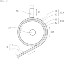
Fig. 4] Fig. 4 is a front view schematically illustrating a winding portion and a second heating element in the thermal transfer system according to the present embodiment. - [
Fig. 5A] Fig. 5A is a perspective view illustrating the second heating element according to the present embodiment. - [
Fig. 5B] Fig. 5B is a bottom view illustrating the second heating element according to the present embodiment. - [
Fig. 6] Fig. 6 is a plan view illustrating the ink ribbon after the ink is transferred by using the second heating element according to the present embodiment. - [
Fig. 7] Fig. 7 is a perspective view illustrating a second heating element in a comparative example. - [
Fig. 8] Fig. 8 is a plan view illustrating the ink ribbon after the ink is transferred by using the second heating element in the comparative example. - [
Fig. 9A] Fig. 9A is a longitudinal sectional view of the ink ribbon and schematically illustrates an aspect of transfer by using the second heating element in the comparative example. - [
Fig. 9B] Fig. 9B is a longitudinal sectional view of the ink ribbon and schematically illustrates the aspect of transfer by using the second heating element in the comparative example. Description of Embodiments - An embodiment (referred to below as the "present embodiment") of the present disclosure will hereinafter be described with reference to the drawings.
- The entire structure of a
thermal transfer system 10 according to the present embodiment will now be described. -
Fig. 1 is a front view schematically illustrating the thermal transfer system according to the present embodiment. - The
thermal transfer system 10 transfers ink to atransfer receiver 14 in a desired pattern by using a belt-like ink ribbon 13 that includes asupport layer 11 and anink layer 12 that is stacked on a surface of thesupport layer 11. - The
thermal transfer system 10 includes a feedingportion 16, multiple feedingguide rollers 15a, afirst heating element 22, aplaten roller 23, multiple windingguide rollers 15b, a windingportion 20, and asecond heating element 50 in order from an upstream position in a direction in which theink ribbon 13 is fed. Thethermal transfer system 10 also includes acontrol unit 24 that controls thefirst heating element 22, thesecond heating element 50, and the windingportion 20. - The feeding
portion 16 rotates in a direction illustrated by using an arrow R1 inFig. 1 and feeds theink ribbon 13 toward a downstream position. - The multiple
feeding guide rollers 15a are arranged at intervals in a direction in which theink ribbon 13 is conveyed and guide theink ribbon 13 that is fed from the feedingportion 16 and that is conveyed toward the downstream position. - The
platen roller 23 faces thefirst heating element 22 with theink ribbon 13 to be conveyed and thetransfer receiver 14 interposed therebetween and supports thetransfer receiver 14. - The multiple winding
guide rollers 15b are arranged at intervals in the direction in which theink ribbon 13 is conveyed and guide theink ribbon 13 that is conveyed from the upstream position to the windingportion 20. - The winding
portion 20 rotates in a direction illustrated by using an arrow R2 inFig. 1 and winds theink ribbon 13 after the ink is transferred by using thefirst heating element 22. - For example, the
control unit 24 outputs a control signal to driving units that drive thefirst heating element 22, thesecond heating element 50, and the windingportion 20 and consequently controls the operation of thefirst heating element 22, thesecond heating element 50, and the windingportion 20 described later. -
Fig. 2A is a plan view illustrating theink ribbon 13 in thethermal transfer system 10 according to the present embodiment.Fig. 2B is a longitudinal sectional view illustrating theink ribbon 13 in thethermal transfer system 10 according to the present embodiment and illustrates a section taken along line A-A inFig. 2A . - The
ink ribbon 13 is a thermal sublimation ink ribbon that contains sublimation dye ink. Theink ribbon 13 includes thesupport layer 11 composed of a substantially transparent material and theink layer 12 that is stacked on thesupport layer 11. - The
support layer 11 is composed of, for example, various kinds of resin films that have sufficient strength and heat resistance to withstand thermal transfer. - The
ink layer 12 includes a Ysublimation ink layer 31, an Msublimation ink layer 32, a Csublimation ink layer 33, anOP ink layer 34, and detection marks 35 that are made between these layers. The Ysublimation ink layer 31 is composed of yellowY sublimation ink 31a. The Msublimation ink layer 32 is composed of magentaM sublimation ink 32a. The Csublimation ink layer 33 is composed of cyanC sublimation ink 33. TheOP ink layer 34 is composed of OP (overprint) ink for forming a substantially transparent protective layer. - The Y
sublimation ink layer 31, the Msublimation ink layer 32, the Csublimation ink layer 33, and theOP ink layer 34 are periodically arranged on thesupport layer 11 in the longitudinal direction (that is, a direction in which theink ribbon 13 extends) of theink ribbon 13. - The three kinds of the sublimation ink in the Y
sublimation ink layer 31, the Msublimation ink layer 32, and the Csublimation ink layer 33 are transferred to thetransfer receiver 14, and consequently, a color image can be printed on thetransfer receiver 14. TheOP ink layer 34 is transferred to thetransfer receiver 14, and consequently, a protective layer for protecting the color image that is printed on thetransfer receiver 14 can be formed. - The detection marks 35 are made on boundary portions among the Y
sublimation ink layer 31, the Msublimation ink layer 32, the Csublimation ink layer 33, and theOP ink layer 34. The detection marks 35 are made to identify the positional relationship between theink ribbon 13 and thefirst heating element 22 and the kind of theink layer 12 by using a detection unit (not illustrated) in thethermal transfer system 10. The detection marks 35 have different features (lengths, thicknesses, patterns) depending on the positions at which the detection marks 35 are made. For this reason, when thefirst heating element 22 transfers a predetermined kind of ink to thetransfer receiver 14, thefirst heating element 22 can heat theink layer 12 that contains the predetermined kind of ink, based on information that is acquired from the detection marks 35. In the case where a means for identifying the kind of theink layer 12 such as a color sensor other than the detection marks 35 is used, the detection marks 35 can be omitted. - The sublimation ink to be used is not limited by the three kinds described above, but sublimation ink in another color may be used, or a single kind, two kinds, or four kinds or more of sublimation ink may be used.
- An example of the
first heating element 22 is a thermal head that includes a heat generating element that generates heat due to energization. Thefirst heating element 22 is disposed so as to face thesupport layer 11 of theink ribbon 13 as illustrated in an enlarged view at a lower position inFig. 1 . Thefirst heating element 22 heats theink ribbon 13 from thesupport layer 11. Thefirst heating element 22 heats the ink in theink layer 12 of theink ribbon 13 in a first pattern that is a predetermined pattern corresponding to, for example, ID information such as a face image, and consequently, the ink in theink layer 12 of theink ribbon 13 is transferred to thetransfer receiver 14 in the first pattern. - The first pattern corresponds to a face image that represents the face of a person to be transferred to an identification, that is, an ID card, such as a photograph in a driver license, an employee identification card, or a passport. Strictly speaking, the transfer patterns of the Y
sublimation ink layer 31, the Msublimation ink layer 32, and the Csublimation ink layer 33 differ from each other, but these are collectively referred to as the first pattern in the present specification. - The transfer of the ink to the
transfer receiver 14 in the first pattern by using thefirst heating element 22 will now be specifically described. - The
transfer receiver 14 is first conveyed to a position between thefirst heating element 22 and theplaten roller 23 by using a conveyance unit (not illustrated) that conveys thetransfer receiver 14. The windingportion 20 rotates in the R2 direction inFig. 1 and winds theink ribbon 13. The feedingportion 16 rotates in the R1 direction inFig. 1 and feeds theink ribbon 13 to the downstream position. Theink ribbon 13 that is fed from the feedingportion 16 passes through the multiple feeding guide rollers 15 and reaches a position between thefirst heating element 22 and theplaten roller 23. - The detection unit (not illustrated) that detects the detection marks 35 of the
ink ribbon 13 detects the Ysublimation ink layer 31 that reaches the position between thefirst heating element 22 and theplaten roller 23, and thefirst heating element 22 is pressed against thetransfer receiver 14 while heating the Ysublimation ink layer 31 in the first pattern. Consequently, theY sublimation ink 31a in the Ysublimation ink layer 31 of theink ribbon 13 is transferred to thetransfer receiver 14 in the first pattern. - Subsequently, the
transfer receiver 14 to which theY sublimation ink 31a is transferred is returned to the position between thefirst heating element 22 and theplaten roller 23 toward the upstream position. Theink ribbon 13 is conveyed further toward the downstream position by using the windingportion 20 and the feedingportion 16. The detection unit (not illustrated) detects the Msublimation ink layer 32 that reaches the position between thefirst heating element 22 and theplaten roller 23, and thefirst heating element 22 is pressed against thetransfer receiver 14 while heating the Msublimation ink layer 32 in the first pattern. Consequently, theY sublimation ink 32a in the Msublimation ink layer 32 of theink ribbon 13 is transferred to thetransfer receiver 14 in the first pattern. - Subsequently, the
transfer receiver 14 to which theY sublimation ink 31a and theM sublimation ink 32a are transferred is returned to the position between thefirst heating element 22 and theplaten roller 23 toward the upstream position. Theink ribbon 13 is conveyed further toward the downstream position by using the windingportion 20 and the feedingportion 16. The detection unit (not illustrated) detects the Csublimation ink layer 33 that reaches the position between thefirst heating element 22 and theplaten roller 23, and thefirst heating element 22 is pressed against thetransfer receiver 14 while heating the Csublimation ink layer 33 in the first pattern. Consequently, theC sublimation ink 33a in the Csublimation ink layer 33 of theink ribbon 13 is transferred to thetransfer receiver 14 in the first pattern. - Subsequently, the
transfer receiver 14 to which theY sublimation ink 31a, theM sublimation ink 32a, and theC sublimation ink 33a are transferred is returned to the position between thefirst heating element 22 and theplaten roller 23 toward the upstream position. Theink ribbon 13 is conveyed further toward the downstream position by using the windingportion 20 and the feedingportion 16. The detection unit (not illustrated) detects theOP ink layer 34 that reaches the position between thefirst heating element 22 and theplaten roller 23, and thefirst heating element 22 is pressed against thetransfer receiver 14 while heating theOP ink layer 34 in a predetermined pattern (a protection pattern) that covers the first pattern. Consequently,OP ink 34a in theOP ink layer 34 of theink ribbon 13 is transferred to thetransfer receiver 14 in the protection pattern. - The
first heating element 22 thus repeats the transfer of the ink to thetransfer receiver 14 in the first pattern or the protection pattern whenever theink ribbon 13 in a predetermined feed amount corresponding to an interval between the detection marks 35 is fed from the feedingportion 16. -
Fig. 3A is a plan view illustrating theink ribbon 13 after the ink is transferred by using thefirst heating element 22.Fig. 3B is a longitudinal sectional view illustrating theink ribbon 13 after the ink is transferred by using thefirst heating element 22 and illustrates a section taken along line B-B inFig. 3A . - With the result that the
first heating element 22 transfers the ink as described above, ink-missingportions sublimation ink layer 31, the Msublimation ink layer 32, and the Csublimation ink layer 33 of theink ribbon 13, and an ink-missingportion 34b in the protection pattern is formed in theOP ink layer 34. In this case, as illustrated inFig. 3A , the patterns of the ink-missingportions ink ribbon 13 after the ink is transferred correspond to the first pattern regarding thefirst heating element 22 described above. For this reason, the ID information such as the face image that is printed on thetransfer receiver 14 can be identified based on the patterns of the ink-missingportions -
Fig. 4 is a front view schematically illustrating the windingportion 20 and thesecond heating element 50 in thethermal transfer system 10 according to the present embodiment. - As illustrated in
Fig. 4 , the windingportion 20 winds theink ribbon 13 such that thesupport layer 11 of theink ribbon 13 is located outside theink layer 12. In the present specification, theink ribbon 13 that is located at the outermost circumference regarding theink ribbon 13 that is wound around the windingportion 20 is referred to as anouter ink ribbon 13A, and theink ribbon 13 that is wound around the winding portion 21 inside theouter ink ribbon 13A and that is adjacent to theouter ink ribbon 13A is referred to as aninner ink ribbon 13B. - The
second heating element 50 is located near the windingportion 20 and is movable in a direction illustrated by using an arrow R3 inFig. 4 , that is, a direction in which thesecond heating element 50 approaches or leaves from the windingportion 20 by using the power of a drive source, not illustrated, such as a motor. Thesecond heating element 50 moves so as to approach the windingportion 20 and heats theouter ink ribbon 13A from thesupport layer 11 when the windingportion 20 winds theink ribbon 13. -
Fig. 5A is a perspective view illustrating thesecond heating element 50 according to the present embodiment.Fig. 5B is a bottom view illustrating thesecond heating element 50 according to the present embodiment. - The
second heating element 50 includes aheating head 52 that includes a ceramic substrate, ametal plate 53 that is disposed on a surface of theheating head 52 facing theink ribbon 13, and asupport frame 51 that supports theheating head 52 and themetal plate 53. In an example illustrated, theheating head 52 and themetal plate 53 are fixed to thesupport frame 51. - The
metal plate 53 has a thickness of 0.3 mm to 0.5 mm, includes a metal plate body 20a that comes into contact with theink ribbon 13 and asupport plate 53b that is coupled with themetal plate body 53a, and has an L-shaped section as a whole. In an example illustrated inFig. 5A , themetal plate 53 is fixed to thesupport frame 51 in a manner in which thesupport plate 53b is fixed to thesupport frame 51 by using mountingbolts 54. - The
metal plate 53 is composed of, for example, copper or aluminum, is a thin plate as a whole, and has excellent thermal conductivity. Thermally conductive grease (not illustrated) is between theheating head 52 and themetal plate 53. For this reason, heat from theheating head 52 can be transferred to theink ribbon 13 via themetal plate 53 with certainty. - A buffering process is performed on the
metal plate 53 in advance, and the surface roughness thereof (arithmetic average roughness) is 0.004 um to 0.02 µm. - After the buffering process, a surface process such as a plating process, a coating process, or a deposition process is performed on the
metal plate 53, and the surface of themetal plate 53 has excellent slipperiness, wear resistance, and heat resistance. - Specifically, a surface process of reducing friction is performed on the
metal plate 53 by using hard chromium or NIFGRIP made by ULVAC, Inc. A NIFGRIP process means a process in which a eutectoid reaction between electroless nickel and fluorine resin is caused in a process liquid, a film is formed on a copper or aluminum material by using the process liquid such that the film contains fluorine resin in a volume ratio of 30%, and a heat treatment is performed to firmly bring the electroless nickel and the fluorine resin in the film into close contact with each other after the film is formed. The NIFGRIP process is excellent in close contact between the material and the film and belongs to a surface process technique that enables a high-performance composite film that is excellent in mold releasability, non-stickiness, slipperiness, and corrosion resistance to be formed. - As a result of the surface process, the surface roughness (arithmetic average roughness) of the surface of the
metal plate 53 is 0.004 um to 0.02 um, and the coefficient of friction thereof is 0.2 or less, preferably about 0.1 as a whole. - The
second heating element 50 includes acontact portion 530 that comes into contact with theink ribbon 13 when thesecond heating element 50 moves so as to approach the windingportion 20. As for thecontact portion 530, multiple projectingportions 531 that come into contact with theink ribbon 13 and multiple recessedportions 532 that do not come into contact with theink ribbon 13 are alternately arranged in the width direction (that is, the direction perpendicular to the direction in which theink ribbon 13 is conveyed). That is, thecontact portion 530 includes the multiple projectingportions 531 that come into contact with theink ribbon 13 and the multiple recessedportions 532 that do not come into contact with theink ribbon 13, and the multiple projectingportions 531 and the multiple recessedportions 532 are alternately arranged in the width direction. - In the example illustrated in
Fig. 5A andFig. 5B , thecontact portion 530 is disposed on themetal plate body 53a of themetal plate 53 and includes the multiple projectingportions 531 that come into contact with theink ribbon 13 and the recessedportions 532 that are located between the projectingportions 531 and that do not come into contact with theink ribbon 13. The projectingportions 531 have an elongated shape that extends in the direction in which theink ribbon 13 is conveyed. - The
contact portion 530 that includes the projectingportions 531 and the recessedportions 532 can be manufactured, for example, in a manner in which the recessedportions 532 are formed by performing a milling process on thecontact portion 530 that is flat. -
Fig. 6 is a plan view illustrating theink ribbon 13 after the ink is transferred by using thesecond heating element 50 according to the present embodiment. - When the winding
portion 20 winds theink ribbon 13 during the transfer of the ink by using thefirst heating element 22, thesecond heating element 50 moves so as to approach the windingportion 20. At this time, the projectingportions 531 of thecontact portion 530 of themetal plate 53 come into contact with theink ribbon 13. While the projectingportions 531 of thesecond heating element 50 are in contact with theink ribbon 13, the windingportion 20 repeatedly starts winding theink ribbon 13 in a predetermined feed amount and stops winding theink ribbon 13. At this time, thesecond heating element 50 heats theouter ink ribbon 13A from thesupport layer 11. - Consequently, the
second heating element 50 transfers at least a part of the ink in theink layer 12 in a region of theouter ink ribbon 13A in contact with the projectingportions 531 to thesupport layer 11 of theinner ink ribbon 13B in a second pattern DP1 that is a stripe-shaped disturbing pattern that extends in the direction in which theink ribbon 13 is conveyed. - As a result of the transfer, the
ink layer 12 of theouter ink ribbon 13A has the first pattern corresponding to the ID information such as the face image and the stripe-shaped second pattern DP1 that extends in the longitudinal direction of theink ribbon 13. A pattern that has the first pattern and the second pattern DP1 is transferred to thesupport layer 11 of theinner ink ribbon 13B. For this reason, as for theink ribbon 13 after the ink is transferred by using thesecond heating element 50, as illustrated inFig. 6 , it is difficult to recognize the patterns of the ink-missingportions - The second pattern DP1 that is the stripe-shaped disturbing pattern described above will now be described in detail.
-
Fig. 7 is a perspective view illustrating asecond heating element 50 in a comparative example.Fig. 8 is a plan view illustrating theink ribbon 13 after the ink is transferred by using thesecond heating element 50 in the comparative example. - As a result of research, the present inventors of the present disclosure have conceived that the disturbing pattern is transferred by using the
second heating element 50 in the comparative example. - The
second heating element 50 in the comparative example differs from the present embodiment in that acontact portion 530 does not include multiple projecting portions but is flat. The other components of thesecond heating element 50 in the comparative example are the same as those of thesecond heating element 50 according to the present embodiment. - The
second heating element 50 in the comparative example transfers at least a part of the ink in theink layer 12 in a region of theouter ink ribbon 13A in contact with thecontact portion 530 to thesupport layer 11 of theinner ink ribbon 13B in a wide belt-like pattern DP2 that extends in the direction in which theink ribbon 13 is conveyed when theouter ink ribbon 13A is heated from thesupport layer 11. - The wide belt-like pattern DP2 typically overlaps a vertically linear pattern DP3 that extends in the width direction (that is, the direction perpendicular to the direction in which the
ink ribbon 13 is conveyed). The reason is that the windingportion 20 repeatedly starts winding theink ribbon 13 in a predetermined feed amount and stops winding theink ribbon 13 while thecontact portion 530 of thesecond heating element 50 is in contact with theink ribbon 13. That is, theink ribbon 13 is relatively gently heated when the windingportion 20 winds theink ribbon 13, and theink ribbon 13 is relatively strongly heated when the windingportion 20 stops winding theink ribbon 13. For this reason, the amount of the transferred ink differs between positions, and consequently, the vertically linear pattern DP3 overlaps the wide belt-like pattern DP2. - The heat of the
contact portion 530 of thesecond heating element 50 is transferred to not only theouter ink ribbon 13A but also theinner ink ribbon 13B away toward the center of the windingportion 20 and theink ribbon 13 further away toward the center. Consequently, as for theinner ink ribbon 13B and theink ribbon 13 further away toward the center, the ink in theink layer 12 is transferred. For this reason, the period of the vertically linear pattern DP3 that overlaps the wide belt-like pattern DP2 is typically smaller than the predetermined feed amount corresponding to the interval between the detection marks 35 of theink ribbon 13. - As for the
ink ribbon 13 after the ink is transferred by using thesecond heating element 50 in the comparative example, the wide belt-like pattern DP2 that overlaps the vertically linear pattern DP3 makes it difficult to recognize the patterns of the ink-missingportions - As for the
second heating element 50 in the comparative example, however, the present inventors of the present disclosure have found the following problems. -
Fig. 9A and Fig. 9B illustrate longitudinal sectional views of theink ribbon 13 and schematically illustrates an aspect of transfer by using thesecond heating element 50 in the comparative example. - A first finding is that as illustrated in
Fig. 9A andFig. 8 , there is a possibility that the patterns of the ink-missingportions OP ink layer 34 of theink ribbon 13 after the transfer to thesupport layer 11 in the region of theOP ink layer 34 that is substantially transparent by using thesecond heating element 50. - Additional findings are as follows. As the time of heating by using the
second heating element 50 increases, the heat from thesecond heating element 50 is transferred toward the center of the windingportion 20, and this facilitates the transfer of the ink in theink layer 12 of theink ribbon 13 that is wound around the windingportion 20. Consequently, in some cases, the entire ink in theink layer 12 in a region in contact with thecontact portion 530 is transferred to thesupport layer 11 of theink ribbon 13 located inside. As illustrated inFig. 9B , such transfer (referred to below as "complete transfer") results in the transfer of the ink in theink layer 12 of theink ribbon 13 located outside to the region of theink ribbon 13 that becomes substantially transparent due to missing ink in theink layer 12 and that is located inside. Consequently, there is a possibility that the patterns of the ink-missingportions - In view of this, the
second heating element 50 according to the present embodiment includes thecontact portion 530 where the multiple projectingportions 531 and the multiple recessedportions 532 are alternately arranged in the width direction (that is, the direction perpendicular to the direction in which the ink ribbon is conveyed), and the second pattern DP1 that is the stripe-shaped disturbing pattern that extends in the direction in which theink ribbon 13 is conveyed is transferred as described above. - As for the
ink ribbon 13 after the ink is transferred by using thesecond heating element 50 according to the present embodiment, the stripe-shaped second pattern DP1 makes it difficult to recognize the patterns of the ink-missingportions OP ink layer 34 described above. - The projecting
portions 531 of thecontact portion 530 according to the present embodiment have different lengths (referred to below as "projecting portion widths Wa") in the width direction (that is, the direction perpendicular to the direction in which theink ribbon 13 is conveyed) depending on positions at which the projectingportions 531 are located. In the example illustrated inFig. 5B and Fig. 6 , the value of the projecting portion width Wa of the projectingportion 531 that is located at the center of thecontact portion 530 in the width direction is relatively large, and the values of the projecting portion widths Wa of the other projectingportions 531 are relatively small. - In the example illustrated in
Fig. 5B , the recessedportions 532 of thecontact portion 530 have the same length (referred to as a "recessed portion width Wb") in the width direction (that is, the direction perpendicular to the direction in which theink ribbon 13 is conveyed) regardless of positions at which the recessedportions 532 are located. The reason is to make it easy to form the recessedportions 532 by performing the milling process. For this reason, the recessedportions 532 may have different recessed portion widths Wb depending on the positions at which the recessedportions 532 are located. - The projecting
portion 531 that has the relatively large projecting portion width Wa faces a region that overlaps a characteristics part among the ink-missingportions contact portion 530 in the width direction (that is, the direction perpendicular to the direction in which theink ribbon 13 is conveyed). That is, the multiple projectingportions 531 according to the present embodiment include a first projecting portion that has a relatively large projecting portion width Wa and a second projecting portion the projecting portion width of which is relatively small. The first projecting portion is located at the center of thecontact portion 530 in the width direction. The second projecting portion is located in a region other than the center of thecontact portion 530 in the width direction. - The projecting portion width Wa of the projecting
portion 531 that faces the region that overlaps the characteristics part and the recessed portion width Wb of each recessedportion 532 are set such that the characteristics part in the first pattern is effectively divided. Specifically, the projecting portion width Wa is set to be 5% or more and 10% or less of the length of the characteristics part in the width direction (that is, the direction perpendicular to the direction in which theink ribbon 13 is conveyed), and the recessed portion width Wb is set to be 5% or more and 10% or less of the length of the characteristics part in the width direction. This enables the characteristics part in the first pattern to be effectively divided, and it can be consequently more difficult to recognize the patterns of the ink-missingportions - In the example illustrated in
Fig. 5B and Fig. 6 , the projecting portion 531 (the first projecting portion) that has the large projecting portion width Wa faces a region that overlaps the eyes in order to divide the region of the eyes corresponding to characteristics parts in the face image at the ink-missingportions portion 531 that faces the region that overlaps the eyes and the recessed portion width Wb of each recessedportion 532 are set such that the region of the eyes is effectively divided. Specifically, the projecting portion width Wa is set to be 10% or more and 15% or less of the length of the region of the eyes in the width direction (that is, the direction perpendicular to the direction in which theink ribbon 13 is conveyed), and the recessed portion width Wb is set to be 5% or more and 10% or less of the length of the region of the eyes in the width direction. - In the example illustrated in
Fig. 5B and Fig. 6 , the projecting portion widths Wa of the projectingportions 531 that are arranged near both ends of thecontact portion 530 are also relatively large. The reason is that the regions of the eyebrows and the mouth have a characteristics part in the face image in some cases. - The length (referred to below as a "contact portion width Wc") of the
contact portion 530 of thesecond heating element 50 in the width direction (that is, the direction perpendicular to the direction in which theink ribbon 13 is conveyed) is set so as to cover at least main parts of the patterns of the ink-missingportions - From the perspective in the recognition of the patterns of the ink-missing
portions - The
thermal transfer system 10 according to the present embodiment includes the windingportion 20 that winds theink ribbon 13 that includes thesupport layer 11 and theink layer 12 after the ink in theink layer 12 is transferred to thetransfer receiver 14, and theheating element 50 that transfers the ink in theink layer 12 of theink ribbon 13 to thesupport layer 11 of theink ribbon 13 that is located inside theink ribbon 13 in the stripe-shaped disturbing pattern DP1 that extends in the direction in which theink ribbon 13 is conveyed in a manner in which theink ribbon 13 that is wound around the windingportion 20 is heated from thesupport layer 11. Theheating element 50 includes thecontact portion 530 including the multiple projectingportions 531 that come into contact with theink ribbon 13 and the multiple recessedportions 532 that do not come into contact with theink ribbon 13, and the multiple projectingportions 531 and the multiple recessedportions 532 are alternately arranged in the direction perpendicular to the direction in which theink ribbon 13 is conveyed, as described above. - The
thermal transfer system 10 can appropriately disturb the ink-missing portions in the first pattern corresponding to, for example, the ID information and can appropriately prevent secret information from being leaked. Thethermal transfer system 10 is preferably used when the first pattern corresponds to the face image, that is, when thefirst heating element 22 transfers the face image to thetransfer receiver 14, or additionally when thetransfer receiver 14 is an ID card on which the face image is printed. - The embodiment of the present invention is described above by way of example. The present disclosure, however, is not limited to the embodiment described above, and various modifications can be made within the scope of claims.
- For example, the present disclosure is not limited to a structure for transferring a color image by using an ink ribbon that includes an OP ink layer and an ink layer in multiple colors but can be used for a structure for transferring a color image by using multiple ink ribbons that include ink layers or OP ink layers in respective different colors.
-
- 10 thermal transfer system
- 13 ink ribbon
- 11 support layer
- 12 ink layer
- 31 Y sublimation ink layer
- 31a Y sublimation ink, 31b ink-missing portion
- 32 M sublimation ink layer
32a M sublimation ink, 32b ink-missing portion - 33 C sublimation ink layer
33a C sublimation ink, 33b ink-missing portion - 34 OP ink layer
34a OP ink, 34b ink-missing portion - 35 detection mark
- 14 transfer receiver
- 15a feeding guide roller
- 15b winding guide roller
- 16 feeding portion
- 20 winding portion
- 22 first heating element
- 23 platen roller
- 24 control unit
- 50 second heating element
- 51 support frame
- 52 heating head
- 53 metal plate
- 53a metal plate body
- 53b support plate
- 530 contact portion
- 531 projecting portion
- 532 recessed portion
- 54 mounting bolt
Claims (8)
- A thermal transfer system comprising:a winding portion that winds an ink ribbon that includes a support layer and an ink layer after ink in the ink layer is transferred to a transfer receiver; anda heating element that transfers the ink in the ink layer of the ink ribbon to the support layer of the ink ribbon that is located inside the ink ribbon that is wound around the winding portion in a stripe-shaped disturbing pattern that extends in a direction in which the ink ribbon is conveyed in a manner in which the ink ribbon that is wound around the winding portion is heated from the support layer,wherein the heating element includes a contact portion including multiple projecting portions that come into contact with the ink ribbon and multiple recessed portions that do not come into contact with the ink ribbon, the multiple projecting portions and the multiple recessed portions being alternately arranged in a direction perpendicular to the direction in which the ink ribbon is conveyed.
- The thermal transfer system according to Claim 1,wherein the heating element includes a heating head and a metal plate that is disposed on a surface of the heating head facing the ink ribbon, andwherein the contact portion is disposed on a surface of the metal plate facing the ink ribbon.
- The thermal transfer system according to Claim 1 or Claim 2,
wherein the projecting portions and the recessed portions have an elongated shape that extends in the direction in which the ink ribbon is conveyed. - The thermal transfer system according to any one of Claim 1 to Claim 3,wherein the multiple projecting portions include a first projecting portion that has a relatively large projecting portion width that is equal to a length in the direction perpendicular to the direction in which the ink ribbon is conveyed and a second projecting portion the projecting portion width of which is relatively small,wherein the first projecting portion is located at a center of the contact portion in a width direction, andwherein the second projecting portion is located in a region other than the center of the contact portion in the width direction.
- The thermal transfer system according to any one of Claim 1 to Claim 4,
wherein the ink ribbon transfers a face image to the transfer receiver by using the ink. - The thermal transfer system according to Claim 4,wherein the ink ribbon transfers a face image that contains eyes to the transfer receiver by using the ink, andwherein the first projecting portion faces a region that overlaps the eyes in the face image.
- The thermal transfer system according to Claim 5 or Claim 6,
wherein the transfer receiver is an ID card on which the face image is to be printed. - The thermal transfer system according to any one of Claim 1 to Claim 7,
wherein in the ink ribbon, an OP ink layer and the ink layer in multiple colors or a single color are periodically arranged on the support layer.
Applications Claiming Priority (2)
| Application Number | Priority Date | Filing Date | Title |
|---|---|---|---|
| JP2020131844A JP7389968B2 (en) | 2020-08-03 | 2020-08-03 | thermal transfer system |
| PCT/JP2021/028823 WO2022030510A1 (en) | 2020-08-03 | 2021-08-03 | Heat transfer system |
Publications (3)
| Publication Number | Publication Date |
|---|---|
| EP4190579A1 true EP4190579A1 (en) | 2023-06-07 |
| EP4190579A4 EP4190579A4 (en) | 2024-08-07 |
| EP4190579B1 EP4190579B1 (en) | 2025-10-01 |
Family
ID=80118114
Family Applications (1)
| Application Number | Title | Priority Date | Filing Date |
|---|---|---|---|
| EP21852360.3A Active EP4190579B1 (en) | 2020-08-03 | 2021-08-03 | Thermal transfer system |
Country Status (4)
| Country | Link |
|---|---|
| US (1) | US12246542B2 (en) |
| EP (1) | EP4190579B1 (en) |
| JP (2) | JP7389968B2 (en) |
| WO (1) | WO2022030510A1 (en) |
Family Cites Families (10)
| Publication number | Priority date | Publication date | Assignee | Title |
|---|---|---|---|---|
| JPH0193374A (en) * | 1987-10-05 | 1989-04-12 | Rohm Co Ltd | End face type thermal head |
| US4788559A (en) * | 1987-12-01 | 1988-11-29 | Miltope Corporation | Apparatus and method for removing an image from the ribbon of a thermal transfer printer |
| JPH0219558A (en) * | 1988-07-07 | 1990-01-23 | Tokyo Kihan:Kk | Impregnating device |
| JPH0219558U (en) * | 1988-07-25 | 1990-02-08 | ||
| US7349002B2 (en) * | 2003-12-26 | 2008-03-25 | Nisca Corporation | Thermal transfer film and thermal transfer printing apparatus |
| JP5772717B2 (en) * | 2011-05-30 | 2015-09-02 | 信越化学工業株式会社 | Pattern formation method |
| JP5800230B2 (en) | 2011-11-29 | 2015-10-28 | 大日本印刷株式会社 | Thermal transfer system and thermal transfer method, winding device and winding method |
| JP5920658B2 (en) * | 2012-03-27 | 2016-05-18 | 大日本印刷株式会社 | Thermal transfer system |
| DE112017004868T5 (en) * | 2016-09-28 | 2019-06-27 | Dai Nippon Printing Co., Ltd. | Heat transfer system, winding device, heat transfer method and winding method |
| JP6878888B2 (en) * | 2016-12-28 | 2021-06-02 | 大日本印刷株式会社 | Thermal transfer system |
-
2020
- 2020-08-03 JP JP2020131844A patent/JP7389968B2/en active Active
-
2021
- 2021-08-03 EP EP21852360.3A patent/EP4190579B1/en active Active
- 2021-08-03 WO PCT/JP2021/028823 patent/WO2022030510A1/en not_active Ceased
- 2021-08-03 US US18/006,619 patent/US12246542B2/en active Active
-
2023
- 2023-11-08 JP JP2023190936A patent/JP7415292B1/en active Active
Also Published As
| Publication number | Publication date |
|---|---|
| EP4190579B1 (en) | 2025-10-01 |
| JP2022028448A (en) | 2022-02-16 |
| US12246542B2 (en) | 2025-03-11 |
| EP4190579A4 (en) | 2024-08-07 |
| JP7415292B1 (en) | 2024-01-17 |
| JP7389968B2 (en) | 2023-12-01 |
| WO2022030510A1 (en) | 2022-02-10 |
| JP2024012212A (en) | 2024-01-25 |
| US20230264485A1 (en) | 2023-08-24 |
Similar Documents
| Publication | Publication Date | Title |
|---|---|---|
| KR101491523B1 (en) | Method and apparatus for forming image, surface-property-modifying sheet, and thermal transfer sheet | |
| EP2879877B1 (en) | Transfer lamination | |
| US8536088B2 (en) | Method and apparatus for forming image, surface-property-modifying sheet, and thermal transfer sheet | |
| US10363725B2 (en) | Card substrate warpage reduction | |
| EP4190579B1 (en) | Thermal transfer system | |
| JP2003159886A (en) | Multilayer card and method for manufacturing the same | |
| EP3630491B1 (en) | Out-of-sequence retransfer printing | |
| WO2013137880A1 (en) | Print ribbon residual image obscurement | |
| US20180147876A1 (en) | Transfer lamination | |
| CN105142923A (en) | Card printing and protection method and system | |
| CN110494295B (en) | Retransfer printing process with variable tension and/or transport speed | |
| US20010025692A1 (en) | Peel-off roller for laminated layer | |
| EP3505354B1 (en) | Thermal printhead having asymmetric recording elements | |
| JP2003145846A (en) | Printer | |
| JP7484216B2 (en) | Thermal Transfer System | |
| EP3544820B1 (en) | Contaminant control process in a retransfer card printer | |
| JP7497581B2 (en) | Thermal Transfer System | |
| WO2009037166A1 (en) | Method for printing a lenticular card, printed lenticular card and printer for lenticular card | |
| JP2005332141A (en) | Passbook printing apparatus and printing method | |
| CN108528053A (en) | A kind of intelligence thermal printing apparatus | |
| JP2010519070A (en) | ID document by printing and process for printing such a document | |
| JP3632439B2 (en) | Image forming method for booklet and image forming apparatus used therefor | |
| JP2007001121A (en) | Thermal transfer printer | |
| US20110309067A1 (en) | Heater Device and Method of Making Same | |
| JP2012051283A (en) | Image forming apparatus, image forming method, and program |
Legal Events
| Date | Code | Title | Description |
|---|---|---|---|
| STAA | Information on the status of an ep patent application or granted ep patent |
Free format text: STATUS: THE INTERNATIONAL PUBLICATION HAS BEEN MADE |
|
| PUAI | Public reference made under article 153(3) epc to a published international application that has entered the european phase |
Free format text: ORIGINAL CODE: 0009012 |
|
| STAA | Information on the status of an ep patent application or granted ep patent |
Free format text: STATUS: REQUEST FOR EXAMINATION WAS MADE |
|
| 17P | Request for examination filed |
Effective date: 20230216 |
|
| AK | Designated contracting states |
Kind code of ref document: A1 Designated state(s): AL AT BE BG CH CY CZ DE DK EE ES FI FR GB GR HR HU IE IS IT LI LT LU LV MC MK MT NL NO PL PT RO RS SE SI SK SM TR |
|
| DAV | Request for validation of the european patent (deleted) | ||
| DAX | Request for extension of the european patent (deleted) | ||
| A4 | Supplementary search report drawn up and despatched |
Effective date: 20240708 |
|
| RIC1 | Information provided on ipc code assigned before grant |
Ipc: B41J 2/325 20060101ALI20240702BHEP Ipc: B41J 17/38 20060101AFI20240702BHEP |
|
| GRAP | Despatch of communication of intention to grant a patent |
Free format text: ORIGINAL CODE: EPIDOSNIGR1 |
|
| STAA | Information on the status of an ep patent application or granted ep patent |
Free format text: STATUS: GRANT OF PATENT IS INTENDED |
|
| INTG | Intention to grant announced |
Effective date: 20250415 |
|
| RIN1 | Information on inventor provided before grant (corrected) |
Inventor name: KAMITANI, NOBUYUKI |
|
| GRAS | Grant fee paid |
Free format text: ORIGINAL CODE: EPIDOSNIGR3 |
|
| P01 | Opt-out of the competence of the unified patent court (upc) registered |
Free format text: CASE NUMBER: APP_30627/2025 Effective date: 20250626 |
|
| GRAA | (expected) grant |
Free format text: ORIGINAL CODE: 0009210 |
|
| STAA | Information on the status of an ep patent application or granted ep patent |
Free format text: STATUS: THE PATENT HAS BEEN GRANTED |
|
| AK | Designated contracting states |
Kind code of ref document: B1 Designated state(s): AL AT BE BG CH CY CZ DE DK EE ES FI FR GB GR HR HU IE IS IT LI LT LU LV MC MK MT NL NO PL PT RO RS SE SI SK SM TR |
|
| REG | Reference to a national code |
Ref country code: GB Ref legal event code: FG4D Ref country code: CH Ref legal event code: F10 Free format text: ST27 STATUS EVENT CODE: U-0-0-F10-F00 (AS PROVIDED BY THE NATIONAL OFFICE) Effective date: 20251001 |
|
| REG | Reference to a national code |
Ref country code: DE Ref legal event code: R096 Ref document number: 602021039738 Country of ref document: DE |
|
| REG | Reference to a national code |
Ref country code: IE Ref legal event code: FG4D |
|
| REG | Reference to a national code |
Ref country code: NL Ref legal event code: MP Effective date: 20251001 |
|
| REG | Reference to a national code |
Ref country code: AT Ref legal event code: MK05 Ref document number: 1842154 Country of ref document: AT Kind code of ref document: T Effective date: 20251001 |
|
| PG25 | Lapsed in a contracting state [announced via postgrant information from national office to epo] |
Ref country code: NL Free format text: LAPSE BECAUSE OF FAILURE TO SUBMIT A TRANSLATION OF THE DESCRIPTION OR TO PAY THE FEE WITHIN THE PRESCRIBED TIME-LIMIT Effective date: 20251001 |
|
| PG25 | Lapsed in a contracting state [announced via postgrant information from national office to epo] |
Ref country code: ES Free format text: LAPSE BECAUSE OF FAILURE TO SUBMIT A TRANSLATION OF THE DESCRIPTION OR TO PAY THE FEE WITHIN THE PRESCRIBED TIME-LIMIT Effective date: 20251001 |
|
| REG | Reference to a national code |
Ref country code: LT Ref legal event code: MG9D |
|
| PG25 | Lapsed in a contracting state [announced via postgrant information from national office to epo] |
Ref country code: NO Free format text: LAPSE BECAUSE OF FAILURE TO SUBMIT A TRANSLATION OF THE DESCRIPTION OR TO PAY THE FEE WITHIN THE PRESCRIBED TIME-LIMIT Effective date: 20260101 |
|
| PG25 | Lapsed in a contracting state [announced via postgrant information from national office to epo] |
Ref country code: HR Free format text: LAPSE BECAUSE OF FAILURE TO SUBMIT A TRANSLATION OF THE DESCRIPTION OR TO PAY THE FEE WITHIN THE PRESCRIBED TIME-LIMIT Effective date: 20251001 Ref country code: AT Free format text: LAPSE BECAUSE OF FAILURE TO SUBMIT A TRANSLATION OF THE DESCRIPTION OR TO PAY THE FEE WITHIN THE PRESCRIBED TIME-LIMIT Effective date: 20251001 Ref country code: FI Free format text: LAPSE BECAUSE OF FAILURE TO SUBMIT A TRANSLATION OF THE DESCRIPTION OR TO PAY THE FEE WITHIN THE PRESCRIBED TIME-LIMIT Effective date: 20251001 |
|
| PG25 | Lapsed in a contracting state [announced via postgrant information from national office to epo] |
Ref country code: RS Free format text: LAPSE BECAUSE OF FAILURE TO SUBMIT A TRANSLATION OF THE DESCRIPTION OR TO PAY THE FEE WITHIN THE PRESCRIBED TIME-LIMIT Effective date: 20260101 |
|
| PG25 | Lapsed in a contracting state [announced via postgrant information from national office to epo] |
Ref country code: IS Free format text: LAPSE BECAUSE OF FAILURE TO SUBMIT A TRANSLATION OF THE DESCRIPTION OR TO PAY THE FEE WITHIN THE PRESCRIBED TIME-LIMIT Effective date: 20260201 |
|
| PG25 | Lapsed in a contracting state [announced via postgrant information from national office to epo] |
Ref country code: PT Free format text: LAPSE BECAUSE OF FAILURE TO SUBMIT A TRANSLATION OF THE DESCRIPTION OR TO PAY THE FEE WITHIN THE PRESCRIBED TIME-LIMIT Effective date: 20260202 Ref country code: CZ Free format text: LAPSE BECAUSE OF FAILURE TO SUBMIT A TRANSLATION OF THE DESCRIPTION OR TO PAY THE FEE WITHIN THE PRESCRIBED TIME-LIMIT Effective date: 20251001 |
|
| PG25 | Lapsed in a contracting state [announced via postgrant information from national office to epo] |
Ref country code: PL Free format text: LAPSE BECAUSE OF FAILURE TO SUBMIT A TRANSLATION OF THE DESCRIPTION OR TO PAY THE FEE WITHIN THE PRESCRIBED TIME-LIMIT Effective date: 20251001 |
|
| PG25 | Lapsed in a contracting state [announced via postgrant information from national office to epo] |
Ref country code: LV Free format text: LAPSE BECAUSE OF FAILURE TO SUBMIT A TRANSLATION OF THE DESCRIPTION OR TO PAY THE FEE WITHIN THE PRESCRIBED TIME-LIMIT Effective date: 20251001 |
|
| PG25 | Lapsed in a contracting state [announced via postgrant information from national office to epo] |
Ref country code: BG Free format text: LAPSE BECAUSE OF FAILURE TO SUBMIT A TRANSLATION OF THE DESCRIPTION OR TO PAY THE FEE WITHIN THE PRESCRIBED TIME-LIMIT Effective date: 20251001 |
|
| PG25 | Lapsed in a contracting state [announced via postgrant information from national office to epo] |
Ref country code: LT Free format text: LAPSE BECAUSE OF FAILURE TO SUBMIT A TRANSLATION OF THE DESCRIPTION OR TO PAY THE FEE WITHIN THE PRESCRIBED TIME-LIMIT Effective date: 20251001 |
|
| REG | Reference to a national code |
Ref country code: DE Ref legal event code: R097 Ref document number: 602021039738 Country of ref document: DE |
|
| PG25 | Lapsed in a contracting state [announced via postgrant information from national office to epo] |
Ref country code: SM Free format text: LAPSE BECAUSE OF FAILURE TO SUBMIT A TRANSLATION OF THE DESCRIPTION OR TO PAY THE FEE WITHIN THE PRESCRIBED TIME-LIMIT Effective date: 20251001 |
|
| PG25 | Lapsed in a contracting state [announced via postgrant information from national office to epo] |
Ref country code: DK Free format text: LAPSE BECAUSE OF FAILURE TO SUBMIT A TRANSLATION OF THE DESCRIPTION OR TO PAY THE FEE WITHIN THE PRESCRIBED TIME-LIMIT Effective date: 20251001 |
|
| PG25 | Lapsed in a contracting state [announced via postgrant information from national office to epo] |
Ref country code: IT Free format text: LAPSE BECAUSE OF FAILURE TO SUBMIT A TRANSLATION OF THE DESCRIPTION OR TO PAY THE FEE WITHIN THE PRESCRIBED TIME-LIMIT Effective date: 20251001 |
|
| PG25 | Lapsed in a contracting state [announced via postgrant information from national office to epo] |
Ref country code: EE Free format text: LAPSE BECAUSE OF FAILURE TO SUBMIT A TRANSLATION OF THE DESCRIPTION OR TO PAY THE FEE WITHIN THE PRESCRIBED TIME-LIMIT Effective date: 20251001 |
|
| PG25 | Lapsed in a contracting state [announced via postgrant information from national office to epo] |
Ref country code: SK Free format text: LAPSE BECAUSE OF FAILURE TO SUBMIT A TRANSLATION OF THE DESCRIPTION OR TO PAY THE FEE WITHIN THE PRESCRIBED TIME-LIMIT Effective date: 20251001 |
|
| PG25 | Lapsed in a contracting state [announced via postgrant information from national office to epo] |
Ref country code: SE Free format text: LAPSE BECAUSE OF FAILURE TO SUBMIT A TRANSLATION OF THE DESCRIPTION OR TO PAY THE FEE WITHIN THE PRESCRIBED TIME-LIMIT Effective date: 20251001 |
|
| PLBE | No opposition filed within time limit |
Free format text: ORIGINAL CODE: 0009261 |
|
| STAA | Information on the status of an ep patent application or granted ep patent |
Free format text: STATUS: NO OPPOSITION FILED WITHIN TIME LIMIT |
|
| REG | Reference to a national code |
Ref country code: CH Ref legal event code: L10 Free format text: ST27 STATUS EVENT CODE: U-0-0-L10-L00 (AS PROVIDED BY THE NATIONAL OFFICE) Effective date: 20260812 |