EP4190496A1 - Electric hammer - Google Patents
Electric hammer Download PDFInfo
- Publication number
- EP4190496A1 EP4190496A1 EP21871354.3A EP21871354A EP4190496A1 EP 4190496 A1 EP4190496 A1 EP 4190496A1 EP 21871354 A EP21871354 A EP 21871354A EP 4190496 A1 EP4190496 A1 EP 4190496A1
- Authority
- EP
- European Patent Office
- Prior art keywords
- bearing
- electric hammer
- mounting shaft
- axis
- assembly
- Prior art date
- Legal status (The legal status is an assumption and is not a legal conclusion. Google has not performed a legal analysis and makes no representation as to the accuracy of the status listed.)
- Withdrawn
Links
- 230000005540 biological transmission Effects 0.000 claims description 128
- 230000004308 accommodation Effects 0.000 claims description 26
- 230000013011 mating Effects 0.000 claims description 14
- 239000000314 lubricant Substances 0.000 description 6
- 239000000463 material Substances 0.000 description 4
- 238000003754 machining Methods 0.000 description 3
- 238000013459 approach Methods 0.000 description 2
- 239000011449 brick Substances 0.000 description 2
- 238000006243 chemical reaction Methods 0.000 description 2
- 239000004567 concrete Substances 0.000 description 2
- 230000008878 coupling Effects 0.000 description 2
- 238000010168 coupling process Methods 0.000 description 2
- 238000005859 coupling reaction Methods 0.000 description 2
- -1 floor slabs Substances 0.000 description 2
- 239000004575 stone Substances 0.000 description 2
- 229910000831 Steel Inorganic materials 0.000 description 1
- 238000005299 abrasion Methods 0.000 description 1
- 230000000694 effects Effects 0.000 description 1
- 230000005484 gravity Effects 0.000 description 1
- 239000010959 steel Substances 0.000 description 1
Images







Classifications
-
- B—PERFORMING OPERATIONS; TRANSPORTING
- B25—HAND TOOLS; PORTABLE POWER-DRIVEN TOOLS; MANIPULATORS
- B25F—COMBINATION OR MULTI-PURPOSE TOOLS NOT OTHERWISE PROVIDED FOR; DETAILS OR COMPONENTS OF PORTABLE POWER-DRIVEN TOOLS NOT PARTICULARLY RELATED TO THE OPERATIONS PERFORMED AND NOT OTHERWISE PROVIDED FOR
- B25F5/00—Details or components of portable power-driven tools not particularly related to the operations performed and not otherwise provided for
- B25F5/02—Construction of casings, bodies or handles
-
- B—PERFORMING OPERATIONS; TRANSPORTING
- B25—HAND TOOLS; PORTABLE POWER-DRIVEN TOOLS; MANIPULATORS
- B25D—PERCUSSIVE TOOLS
- B25D16/00—Portable percussive machines with superimposed rotation, the rotational movement of the output shaft of a motor being modified to generate axial impacts on the tool bit
- B25D16/006—Mode changers; Mechanisms connected thereto
-
- B—PERFORMING OPERATIONS; TRANSPORTING
- B25—HAND TOOLS; PORTABLE POWER-DRIVEN TOOLS; MANIPULATORS
- B25D—PERCUSSIVE TOOLS
- B25D11/00—Portable percussive tools with electromotor or other motor drive
- B25D11/06—Means for driving the impulse member
- B25D11/062—Means for driving the impulse member comprising a wobbling mechanism, swash plate
-
- B—PERFORMING OPERATIONS; TRANSPORTING
- B25—HAND TOOLS; PORTABLE POWER-DRIVEN TOOLS; MANIPULATORS
- B25D—PERCUSSIVE TOOLS
- B25D16/00—Portable percussive machines with superimposed rotation, the rotational movement of the output shaft of a motor being modified to generate axial impacts on the tool bit
- B25D16/003—Clutches specially adapted therefor
-
- B—PERFORMING OPERATIONS; TRANSPORTING
- B25—HAND TOOLS; PORTABLE POWER-DRIVEN TOOLS; MANIPULATORS
- B25D—PERCUSSIVE TOOLS
- B25D2216/00—Details of portable percussive machines with superimposed rotation, the rotational movement of the output shaft of a motor being modified to generate axial impacts on the tool bit
- B25D2216/0007—Details of percussion or rotation modes
- B25D2216/0023—Tools having a percussion-and-rotation mode
-
- B—PERFORMING OPERATIONS; TRANSPORTING
- B25—HAND TOOLS; PORTABLE POWER-DRIVEN TOOLS; MANIPULATORS
- B25D—PERCUSSIVE TOOLS
- B25D2216/00—Details of portable percussive machines with superimposed rotation, the rotational movement of the output shaft of a motor being modified to generate axial impacts on the tool bit
- B25D2216/0007—Details of percussion or rotation modes
- B25D2216/0038—Tools having a rotation-only mode
-
- B—PERFORMING OPERATIONS; TRANSPORTING
- B25—HAND TOOLS; PORTABLE POWER-DRIVEN TOOLS; MANIPULATORS
- B25D—PERCUSSIVE TOOLS
- B25D2216/00—Details of portable percussive machines with superimposed rotation, the rotational movement of the output shaft of a motor being modified to generate axial impacts on the tool bit
- B25D2216/0084—Mode-changing mechanisms
-
- B—PERFORMING OPERATIONS; TRANSPORTING
- B25—HAND TOOLS; PORTABLE POWER-DRIVEN TOOLS; MANIPULATORS
- B25D—PERCUSSIVE TOOLS
- B25D2217/00—Details of, or accessories for, portable power-driven percussive tools
- B25D2217/0011—Details of anvils, guide-sleeves or pistons
- B25D2217/0019—Guide-sleeves
-
- B—PERFORMING OPERATIONS; TRANSPORTING
- B25—HAND TOOLS; PORTABLE POWER-DRIVEN TOOLS; MANIPULATORS
- B25D—PERCUSSIVE TOOLS
- B25D2250/00—General details of portable percussive tools; Components used in portable percussive tools
- B25D2250/091—Electrically-powered tool components
- B25D2250/095—Electric motors
-
- B—PERFORMING OPERATIONS; TRANSPORTING
- B25—HAND TOOLS; PORTABLE POWER-DRIVEN TOOLS; MANIPULATORS
- B25D—PERCUSSIVE TOOLS
- B25D2250/00—General details of portable percussive tools; Components used in portable percussive tools
- B25D2250/121—Housing details
-
- B—PERFORMING OPERATIONS; TRANSPORTING
- B25—HAND TOOLS; PORTABLE POWER-DRIVEN TOOLS; MANIPULATORS
- B25D—PERCUSSIVE TOOLS
- B25D2250/00—General details of portable percussive tools; Components used in portable percussive tools
- B25D2250/331—Use of bearings
Definitions
- the present application relates to a power tool, for example, an electric hammer.
- Electric hammers are widely used power tools and mainly used for perforating concrete, floor slabs, brick walls, and stone.
- many electric hammers implement a perforation function and are adjustable to an appropriate position and matched with an appropriate drill bit so that the electric hammers can replace ordinary electric drills, which are a hammer drill mode and a drill mode.
- the present application provides an electric hammer which has a simple structure and is convenient for a user to switch functions.
- An example provides an electric hammer including a housing, an electric motor, an output assembly, an impact assembly, and a mounting shaft.
- the electric motor is at least partially disposed in the housing.
- the output assembly includes a sleeve rotatable about a first axis.
- the impact assembly includes a swash bearing and an impact block capable of being driven by the swash bearing to reciprocate in the sleeve, where the impact block is capable of outputting an impact force forward when moving in the sleeve.
- the mounting shaft is used for mounting the swash bearing, where the mounting shaft is capable of being driven by the electric motor to rotate about a second axis.
- the electric hammer has a drill mode and a hammer drill mode; when the electric hammer is in the drill mode, the sleeve rotates; and when the electric hammer is in the hammer drill mode, the sleeve rotates and the impact block reciprocates in the sleeve.
- the electric hammer further includes a clutch assembly and a switching assembly.
- the clutch assembly has a first state in which the swash bearing is capable of being driven to move with the mounting shaft and a second state in which the mounting shaft is allowed to rotate relative to the swash bearing.
- the switching assembly is configured to switch the clutch assembly between the first state and the second state and includes a switching element, where the switching element includes a forced end and a drive end, the output assembly moving along the first axis drives the forced end to move, and the drive end is configured to drive the clutch assembly to be switched to the first state.
- the switching element is disposed on a lower side of the first axis.
- the switching element is disposed between the first axis and the second axis.
- the sleeve is substantially symmetrical about a vertical plane; and a portion of the switching element between the first axis and the second axis is distributed on two sides of the vertical plane.
- the electric hammer further includes a first transmission member configured to receive power outputted from the electric motor to drive the mounting shaft to rotate.
- the clutch assembly includes an input portion and an output portion. The input portion rotates synchronously with the first transmission member or the mounting shaft, and the output portion for mating with the input portion drives the swash bearing to move, where the swash bearing is slidable on the mounting shaft along the second axis, the output portion is slidable with the swash bearing along the second axis, and the switching element is disposed on a front side of the swash bearing and is capable of driving a whole formed by the swash bearing and the output portion to slide along the second axis.
- the swash bearing includes a bearing core mounted to the mounting shaft, where the bearing core extends toward the first transmission member to form the output portion.
- the output assembly further includes a first transmission portion and a second transmission portion.
- the first transmission portion is fixedly connected to the sleeve, and the second transmission portion rotates synchronously with the mounting shaft and drives the first transmission portion to rotate, where the forced end of the switching element abuts against the first transmission portion.
- the electric hammer further includes a support bracket fixedly connected to or integrally formed with the housing, where the support bracket is configured to support the mounting shaft, and a guide slot for the switching element to move along is formed on or fixedly connected to the support bracket.
- the switching element is disposed between the sleeve and the mounting shaft.
- the output assembly further includes a first transmission portion and a second transmission portion.
- the first transmission portion is fixedly connected to the sleeve, and the second transmission portion rotates synchronously with the mounting shaft and drives the first transmission portion to rotate, where an orthographic projection of the first transmission portion on a plane perpendicular to the first axis has a highest point and a lowest point, and an orthographic projection of the switching element on the plane is located between the highest point and the lowest point.
- An electric hammer includes a housing, an electric motor, an output assembly, an impact assembly, and a mounting shaft.
- the electric motor is at least partially disposed in the housing.
- the output assembly includes a sleeve rotatable about a first axis.
- the impact assembly includes a swash bearing and an impact block capable of being driven by the swash bearing to reciprocate in the sleeve, where the impact block is capable of outputting an impact force forward when moving in the sleeve.
- the mounting shaft is used for mounting the swash bearing, where the mounting shaft is capable of being driven by the electric motor to rotate about a second axis.
- the electric hammer has a drill mode and a hammer drill mode; when the electric hammer is in the drill mode, the sleeve rotates; and when the electric hammer is in the hammer drill mode, the sleeve rotates and the impact block reciprocates in the sleeve.
- the electric hammer further includes a clutch assembly and a switching assembly.
- the clutch assembly has a first state in which the swash bearing is capable of being driven to move with the mounting shaft and a second state in which the mounting shaft is allowed to rotate relative to the swash bearing.
- the switching assembly is configured to switch the clutch assembly between the first state and the second state, where the switching assembly includes a switching element disposed between the first axis and the second axis.
- the electric hammer further includes a transmission assembly including a first transmission member capable of being driven by the electric motor to rotate about the second axis, where the first transmission member is fixedly connected to the mounting shaft.
- the swash bearing includes a bearing core mounted on the mounting shaft, where when the electric hammer is in the hammer drill mode, the sleeve rotates and the bearing core rotates synchronously with the mounting shaft.
- the swash bearing is slidable on the mounting shaft along the second axis to a first position and a second position, where when the swash bearing is at the first position, the bearing core rotates synchronously with the mounting shaft, and when the swash bearing is at the second position, the mounting shaft is rotatable relative to the bearing core.
- the electric hammer further includes a locking element, where when the swash bearing is at the second position, the locking element is configured to restrain the bearing core from rotating, and when the swash bearing is at the first position, the locking element allows the bearing core to rotate.
- the bearing core is connected to an engagement portion which is configured to mate with the locking element.
- the transmission assembly includes an input portion configured to output power to the swash bearing, and the bearing core is connected to an output portion which mates with the input portion when the swash bearing is at the first position.
- the output portion and the engagement portion are disposed at two ends of the bearing core separately.
- the locking element is fixedly connected to or integrally formed with the housing.
- the bearing core protrudes forward and forms an engagement portion.
- the electric hammer further includes the switching element configured to drive the swash bearing to move toward the first position so as to cause the electric hammer to enter the hammer drill mode.
- an engagement portion is disposed at an end of the bearing core facing the switching element.
- the electric hammer further includes a reset member biasing the swash bearing to move toward a position where an engagement portion mates with the locking element.
- the electric hammer further includes a transmission assembly including a first transmission member capable of being driven by the electric motor to rotate about the second axis, where the first transmission member is fixedly connected to the mounting shaft.
- the swash bearing includes a bearing core mounted on the mounting shaft, where when the electric hammer is in the hammer drill mode, the sleeve rotates and the bearing core rotates synchronously with the mounting shaft.
- the swash bearing is slidable on the mounting shaft along the second axis to a first position and a second position, where when the swash bearing is at the first position, the bearing core rotates synchronously with the mounting shaft, and when the swash bearing is at the second position, the mounting shaft is rotatable relative to the bearing core.
- the electric hammer further includes a locking element, where when the swash bearing is at the first position, the locking element is separated from the bearing core to allow the bearing core to rotate, and when the swash bearing is at the second position, the locking element meshes with the bearing core to restrain the bearing core from rotating.
- the electric hammer includes a main body including the housing.
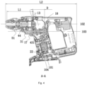
- the sleeve has a length L1 along a direction of the first axis
- the main body has a length L2 along the direction of the first axis
- the housing has a length L3 in a direction perpendicular to the first axis, where a ratio of the length L2 to the length L1 is greater than or equal to 2.5 and less than or equal to 4, and the length L3 is greater than or equal to 55 mm and less than 70 mm.
- the output assembly further includes a first transmission portion mating with the mounting shaft and configured to transmit power of the electric motor to the sleeve, where the first transmission portion includes a rotating member fixedly connected to the sleeve and an intermediate member mating with the rotating member; where an accommodation space configured to accommodate the intermediate member is formed on the rotating member.
- a diameter of the accommodation space is smaller than a root diameter of the rotating member.
- a transmission assembly further includes an input portion configured to output power to the swash bearing, and the swash bearing is connected to an output portion which mates with the input portion, where when the electric hammer is in the drill mode, the output portion is separated from the output portion, and when the electric hammer is in the hammer drill mode, the output portion is coupled to the input portion.
- the swash bearing includes a bearing core mounted on the mounting shaft, where the bearing core protrudes rearward and forms the output portion; and a first transmission member is recessed inward to form the input portion.
- the electric hammer further includes the switching element configured to drive the swash bearing to move along the second axis so as to cause the output portion to be coupled to the input portion.
- the electric hammer further includes a shift assembly including a limiting portion configured to prevent the switching element from moving rearward along the direction of the first axis, where a stopper portion configured to mate with the limiting portion is fixedly connected to or integrally formed with the switching element, when the electric hammer is in the drill mode, the limiting portion abuts against the stopper portion to prevent the switching element from moving rearward along the direction of the first axis, and when the electric hammer is in the hammer drill mode, the limiting portion is separated from the stopper portion to allow the switching element to move rearward along the direction of the first axis.
- a shift assembly including a limiting portion configured to prevent the switching element from moving rearward along the direction of the first axis, where a stopper portion configured to mate with the limiting portion is fixedly connected to or integrally formed with the switching element, when the electric hammer is in the drill mode, the limiting portion abuts against the stopper portion to prevent the switching element from moving rearward along the direction
- the electric hammer further includes a first bearing and a second bearing which are mounted onto the mounting shaft to support the mounting shaft; where a distance between the first bearing and the second bearing along a direction of the second axis is greater than or equal to 30 mm and less than or equal to 50 mm.
- first bearing and the second bearing are disposed on two sides of the swash bearing separately, and the first transmission portion is disposed on a front side of the first bearing and the second bearing.
- a length of the sleeve along a direction of the first axis is less than or equal to 101 mm.
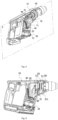
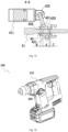
- An electric hammer 100 shown in FIG. 1 can drive a functional element 61 to rotate, and the functional element 61 may be a drill bit. In this manner, the electric hammer 100 can drive the functional element 61 to perforate hard materials such as wall surfaces, concrete, bricks, and stone.
- FIG. 1 To clearly illustrate the technical solutions of the present application, up, down, front, rear, left, and right shown in FIG. 1 are defined.
- FIGS. 1 to 15 show the schematic views of the structure of an electric hammer in a first example.
- the electric hammer 100 includes a main body 100a and an energy source, and the main body 100a includes a housing 10, a power assembly 20, a transmission assembly 30, an impact assembly 40, an output assembly 50, a clamping assembly 60, and the energy source.
- the energy source may be specifically a battery pack 110.
- the housing 10 is formed with an accommodation space 11 configured to accommodate various parts in the electric hammer 100. That is, the power assembly 20, the output assembly 50, the transmission assembly 30, and the impact assembly 40 are at least partially disposed in the accommodation space 11.
- the housing 10 is formed with or connected to a handle portion 12 which may be held by a user. The user may operate the electric hammer 100 by holding the handle portion 12.
- the power assembly 20 is used for supplying power to the electric hammer 100 and includes an electric motor 21, where the electric motor 21 includes an electric motor shaft 22 rotatable about an electric motor axis 101.
- the transmission assembly 30 is configured to transmit the power outputted from the electric motor shaft 22 to the output assembly 50 and the impact assembly 40.
- the output assembly 50 includes a sleeve 51 which can be driven by the transmission assembly 30 to rotate about a first axis 102.
- the sleeve 51 is formed with a receiving cavity configured to receive the functional element 61, and the functional element 61 may be inserted into the receiving cavity.
- the clamping assembly 60 may keep the functional element 61 on the sleeve 51.
- the impact assembly 40 includes a swash bearing 40a and an impact block 44, where the swash bearing can be driven by the transmission assembly 30 to impact the impact block 44, and the impact block 44 can be in contact with the functional element 61 mounted in the sleeve 51. In this manner, when the swash bearing 40a reciprocally impacts the impact block 44, the impact block 44 can intermittently output an impact force to the functional element 61 so that the functional element 61 performs perforation more efficiently.
- the energy source is used for supplying energy to the electric hammer 100.
- the energy source may be an alternating current or a direct current.
- the direct current is adopted in this example, that is, the energy source is specifically the battery pack 110.
- the battery pack 110 may be inserted into the housing 10, or the battery pack 110 may be separated from the housing 10, that is, the battery pack 110 is not directly mounted on the surface of the housing 10. As long as a power source can be supplied, a specific mounting manner is not limited here.
- the electric hammer 100 further includes a clutch assembly 80.
- the clutch assembly 80 is configured to disable or enable the power transmission between the transmission assembly 30 and the impact assembly 40.
- the clutch assembly 80 has a first state and a second state. When the clutch assembly 80 is in the first state, the clutch assembly 80 can transmit the power outputted from the transmission assembly to the impact assembly 40, and in this case, the impact assembly 40 can output the impact force to the functional element 61.
- the clutch assembly 80 is in the first state (as shown in FIG. 6 )
- the functional element 61 is not only driven by the output assembly 50 to rotate about the first axis 102 but also receives a driving force outputted from the impact assembly 40.
- the electric hammer 100 is in a hammer drill mode.
- the clutch assembly 80 When the clutch assembly 80 is in the second state (as shown in FIG. 2 ), the clutch assembly 80 disables the power transmission between the transmission assembly 30 and the impact assembly 40, and the transmission assembly 30 no longer drives the impact assembly 40. In this case, the impact assembly 40 cannot output the impact force to the functional element 61. Thus, when the clutch assembly 80 is in the second state, the functional element 61 cannot be driven by the impact assembly 40 and can only be driven by the output assembly 50 to rotate about the first axis 102. Thus, the electric hammer 100 is in a drill mode.
- the electric hammer 100 further includes a switching assembly 70.
- the switching assembly 70 is configured to switch the electric hammer 100 between the drill mode and the hammer drill mode.
- the switching assembly 70 can transmit a driving force from the output assembly 50 to the clutch assembly 80, thereby switching the clutch assembly 80 to the first state.
- the functional element 61 is pressed to move the sleeve 51 along the direction of the first axis 102 so that the switching assembly 70 drives the clutch assembly 80 to switch to the first state.
- the electric hammer 100 is switched to the hammer drill mode. That is to say, the user can switch the electric hammer 100 to the hammer drill mode without excessive operation steps, thereby facilitating the use of the user, saving time, and improving working efficiency.
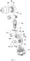
- the transmission assembly 30 includes a mounting shaft 31, a first transmission member 32, and a second transmission member 23.
- the second transmission member 23 is fixedly connected to the electric motor shaft 22, and the first transmission member 32 meshes with the second transmission member 23 to receive the power outputted from the electric motor 21.
- the mounting shaft 31 is fixedly connected to the first transmission member 32, that is to say, when the first transmission member 32 rotates, the mounting shaft 31 rotates with the first transmission member 32.
- the electric motor 21 may output the power to the mounting shaft 31 through the first transmission member 32 and the second transmission member 23 to drive the mounting shaft 31 to rotate about a second axis 103, where the second axis 103 and the first axis 102 are parallel to each other.
- the first transmission member 32 is a bevel gear
- the second transmission member 23 is a bevel gear portion which is formed by the electric motor shaft 22 and meshes with the bevel gear.
- the first transmission member 32 and the second transmission member 23 may be other structures, and the specific structures thereof are not limited here as long as a force can be transmitted.
- the output assembly 50 further includes a first transmission portion 52, and a second transmission portion 311 is formed on the mounting shaft 31.
- the first transmission portion 52 is fixedly mounted to the sleeve 51
- the second transmission portion 311 is fixedly mounted to the mounting shaft 31 to rotate synchronously with the mounting shaft 31.
- the first transmission portion 52 and the second transmission portion 311 are both transmission gears, and the first transmission portion 52 and the second transmission portion 311 mesh with each other.
- the electric motor drives the mounting shaft 31 to perform transmission
- the second transmission portion 311 on the mounting shaft 31 drives the whole formed by the first transmission portion 52 and the sleeve 51 to rotate so that the sleeve 51 drives the functional element 61 to rotate.
- the swash bearing 40a in the impact assembly 40 includes a striking member 41, a swing link 42, and a bearing core 43.
- the striking member 41 can reciprocate in the sleeve 51 to impact the impact block 44 so that the impact block 44 impacts the functional element 61.
- the striking member 41 is connected to the swing link 42, the swing link 42 is mounted to the bearing core 43, and the bearing core 43 is used for mounting the swash bearing 40a onto the mounting shaft 31.
- the bearing core 43 can rotate with the mounting shaft 31 or not rotate with the mounting shaft 31.
- the bearing core 43 drives the swing link 42 to reciprocate, and the swing link 42 drives the striking member 41 to reciprocate in the sleeve 51 to strike the impact block 44 so that the impact block 44 can output the impact force to the functional element 61.
- the functional element 61 is subjected to the impact of the impact block 44 while rotating, and the electric hammer 100 is in the hammer drill mode.
- the striking member 41 cannot impact the impact block 44, and the impact block 44 does not output the impact force to the functional element 61.
- the functional element 61 only rotates, and the electric hammer 100 is in the drill mode.
- the clutch assembly 80 When the clutch assembly 80 is in the first state, the clutch assembly 80 can drive the bearing core 43 to rotate with the mounting shaft 31 so that the striking member can reciprocate in the sleeve 51 to drive the impact block 44 to output the impact force to the functional element 61. In this case, the electric hammer 100 is in the hammer drill mode.
- the clutch assembly 80 When the clutch assembly 80 is in the second state, the clutch assembly 80 no longer drives the bearing core 43 to rotate with the mounting shaft 31, the mounting shaft 31 can rotate relative to the impact assembly 40, and the mounting shaft 31 drives the output assembly 50 to rotate so that the functional element 61 is driven to rotate. In this case, the functional element 61 only rotates, that is, the electric hammer 100 is in the drill mode.
- the clutch assembly 80 includes an input portion 81 and an output portion 82.
- the input portion 81 rotates synchronously with the mounting shaft 31, and the output portion 82 rotates synchronously with the bearing core 43 of the swash bearing 40a.
- the output portion 82 can move relative to the input portion 81 so that the input portion 81 can mate with the output portion 82 and the input portion 81 can also get rid of mating with the output portion 82.
- the clutch assembly 80 When the clutch assembly 80 is in the first state, the output portion 82 moves relative to the input portion 81 to a position where the output portion 82 mates with the input portion 81. In this case, the clutch assembly 80 can drive the swash bearing 40a to impact the impact block 44.
- the output portion 82 moves relative to the input portion 81 to a position where the output portion 82 gets rid of mating with the input portion 81. In this case, the clutch assembly 80 cannot drive the swash bearing 40a, and the swash bearing 40a cannot drive the impact block 44.
- the switching assembly 70 includes a switching element 71 including a forced end 711 and a drive end 712.
- the forced end 711 is in contact with the output assembly 50 and can be driven by the output assembly 50 to move along the first axis 102
- the drive end 712 is in contact with the clutch assembly 80 to drive the clutch assembly 80 to be switched between the first state and the second state.
- the output assembly 50 moves relative to the housing 10 along the first axis 102
- the output assembly 50 drives the forced end 711 to move and the forced end 711 drives the drive end 712 to move together, so as to drive the clutch assembly 80 to be switched from the second state to the first state.
- the switching element 71 is disposed on the lower side of the first axis 102.
- the forced end 711 of the switching element 71 is directly connected to the output assembly 50, and the drive end 712 of the switching element 71 directly drives the clutch assembly 80.
- the state of the clutch assembly 80 can be switched only through one switching element 71 disposed on the lower side of the first axis 102 of the sleeve 51, which is not only simple in structure but also fully utilizes the space on the lower side of the first axis 102.
- the whole machine has a compact structure and a more reasonable arrangement.
- the dimension of the sleeve 51 along the direction of the first axis 102 is relatively large, so the sleeve 51 needs to occupy a relatively large space in the direction of the first axis 102.
- the switching element 71 is disposed on the lower side of the first axis 102 so that the space on the lower side of the sleeve 51 can be fully utilized.
- the switching element 71 when the switching element 71 is disposed on the left or right side of the sleeve 51, the dimension of the whole formed by the sleeve 51 and the switching element 71 in a left and right direction is relatively large, and thus the housing 10 can be prevented from too large a dimension in the left and right direction.
- the electric hammer 100 can conveniently perform perforation against a left or right wall.
- the following case is also avoided: when the switching element 71 is disposed on the upper side of the first axis 102, the upper surface of the housing 10 is relatively far from the first axis.
- the electric hammer 100 conveniently performs perforation against an upper wall.
- the switching element 71 is disposed on the lower side of the first axis, and when the output assembly 50 moves rearward along the first axis, the clutch assembly 80 can be switched to the first state through the forced end of the switching element 71 and the drive end of the switching element 71 so that the electric hammer is switched from the drill mode to the hammer drill mode.
- the clutch assembly 80 can be switched to the first state through the forced end of the switching element 71 and the drive end of the switching element 71 so that the electric hammer is switched from the drill mode to the hammer drill mode.
- An orthographic projection of the switching element 71 on a plane perpendicular to the first axis 102 at least partially overlaps an orthographic projection of the first transmission portion 52 on the plane perpendicular to the first axis 102. That is to say, the orthographic projection of the first transmission portion 52 on the plane perpendicular to the first axis 102 has a highest point and a lowest point, and the orthographic projection of the switching element 71 on the plane is located between the highest point and the lowest point.
- the forced end 711 of the switching element 71 abuts against the first transmission portion 52, and the drive end 712 of the switching element 71 is connected to the clutch assembly 80.
- the electric hammer 100 is in the hammer drill mode. That is to say, the switching element 71 fully utilizes the space on the lower side of the sleeve 51 so that the structure and the position of the mounting shaft 31 or another part can be well planned, thereby causing the whole machine to have a more reasonable layout.
- the dimension of the switching element 71 in the up and down direction is smaller than the dimension of the first transmission portion 52 in the up and down direction, that is to say, the dimension of the switching element 71 in the up and down direction is smaller than a diameter of the first transmission portion 52, and the switching element 71 is disposed on the lower side of the sleeve 51.
- the switching element 71 is disposed between the first axis 102 and the second axis 103, and the first transmission portion 52 meshes with the mounting shaft 31 so that a position where the first transmission portion 52 meshes with the mounting shaft 31 has a certain height difference in the up and down direction.
- the height difference can be fully utilized, that is to say, the switching element 71 fully utilizes the space on the lower side of the sleeve 51 and the upper side of the mounting shaft 31 so that mode switching can be implemented through the switching element 71 without the adjustment of a structural arrangement.
- the forced end 711 of the switching element 71 may abut against a drive portion formed on the sleeve 51.
- This configuration can also implement a switching function. Specific principles and functions are substantially the same as those in the case where the forced end 711 abuts against the first transmission portion 52. Therefore, the details are not repeated here.
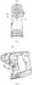
- the sleeve 51 is substantially symmetrical about a vertical plane P, where the vertical plane is a plane along the up and down direction, the first axis 102 is located in the plane P, and a portion of the switching element 71 between the first axis 102 and the second axis 103 is distributed on two sides of the plane P.
- the switching element 71 is made of some wear-resistant materials such as high-density steel so as to ensure the running of the machine. These materials are relatively heavy. With the preceding configuration, the weight of the switching element 71 can be distributed on the two sides of the plane P as much as possible so that the balance of the whole machine can be ensured.
- the electric hammer 100 further includes a shift assembly 90 which is adjustable by the user.
- the shift assembly 90 includes a limiting portion 91 configured to prevent the sleeve 51 or the switching element 71 from moving rearward along the direction of the first axis 102.
- the user may adjust the shift assembly 90 to move the limiting portion 91 to a released position and a restrained position.
- a stopper portion 714 configured to mate with the limiting portion 91 is fixedly connected to or integrally formed with the switching element 71.
- the limiting portion 91 When the user adjusts the shift assembly 90 to move the limiting portion 91 to the restrained position, the limiting portion 91 abuts against the stopper portion 714, and the limiting portion 91 prevents the switching element 71 from moving along the direction parallel to the first axis 102. That is, in this case, the switching element 71 cannot drive the output portion 82 to be coupled to the input portion 81. Thus, the electric hammer 100 is in the drill mode.
- the limiting portion 91 When the user adjusts the shift assembly 90 to move the limiting portion 91 to the released position, the limiting portion 91 is disengaged from the stopper portion 714, and the limiting portion 91 allows the sleeve 51 and the stopper portion to move along the direction of the first axis 102.
- the sleeve 51 moves rearward under the action of an external force, and the switching element 71 moves along the direction parallel to the first axis 102 when receiving a driving force from the sleeve 51 so that the switching element 71 can drive the output portion 82 to be coupled to the input portion 81.
- the electric hammer 100 enters the hammer drill mode.
- the clutch assembly 80 is disposed on the rear side of the swash bearing 40a along the direction of the second axis 103.
- the input portion 81 of the clutch assembly 80 is fixedly connected to or integrally formed with the first transmission member 32
- the output portion 82 of the clutch assembly 80 is fixedly connected to or integrally formed with the bearing core 43.
- the input portion 81 is first meshing teeth formed on the first transmission member 32 and extending toward the bearing core 43
- the output portion 82 is second meshing teeth formed on the bearing core 43 of the swash bearing 40a and facing the first transmission member 32.
- the clutch assembly 80 When the input portion 81 and the output portion 82 are disengaged from each other, the clutch assembly 80 is in the second state.
- the switching element 71 is in contact with the bearing core 43 of the swash bearing 40a.
- the switching element 71 drives the bearing core 43 to move along the direction of the second axis 103 toward the first transmission member 32.
- the output portion 82 on the bearing core 43 moves to a position where the output portion 82 meshes with the input portion 81 on the first transmission member 32 so that the clutch assembly 80 is switched to the first state.
- the electric hammer 100 enters the hammer drill mode.
- the clutch assembly 80 further includes a reset member 83 biased between the swash bearing 40a and the first transmission member 32.
- the reset member 83 is configured to bias an output portion so that the clutch assembly 80 has the tendency to be switched to the second state. In this manner, when the switching element 71 no long receives the driving force of the sleeve 51, the reset member 83 drives the swash bearing 40a to move along the second axis 103 to a state where the output portion 82 is disengaged from the input portion 81. At this time, the clutch assembly 80 is in the second state. Thus, the electric hammer 100 is in the drill mode.
- an end face of the first transmission member 32 is recessed inward to form the input portion 81.
- the end face of the first transmission member 32 is recessed inward so that a slot is formed, and a wall of the slot protrudes toward the second axis 103 to form protruding teeth which constitute the output portion 82.
- the dimension of the whole formed by the output portion 82 and the first transmission member 32 is reduced, which is conducive to reducing the dimension of the transmission assembly 30 along the direction of the second axis 103.
- the output portion 82 meshes with the input portion, the output portion 82 is inserted into the slot so that a movement stroke of the output portion 82 can be increased.
- the output portion 82 extends rearward from an end face of the bearing core 43, the bearing core 43 extends rearward to form an annular portion, and an end face of the annular portion is provided with teeth to form the output portion 82.
- the reset member 83 is disposed between the output portion 82 and the input portion 81 and is specifically a spring at least partially disposed in the annular portion.
- the first transmission portion 52 drives the switching element 71 to slide so that the drive end 712 of the switching element 71 drives the impact assembly 40 to move along the second axis 103.
- the impact assembly 40 is forced to compress the spring, the spring is deformed, and a coupling portion of the bearing core 43 meshes with the input portion 81 of the first transmission member 32 so that the clutch assembly 80 is switched to the first state.
- the spring drives, according to an elastic force thereof, the coupling portion of the bearing core 43 to be disengaged from the input portion 81.
- the impact assembly 40 rotates relative to the mounting shaft 31 so that the impact assembly 40 is switched to the second state.
- the output portion 82 of the bearing core 43 extends into the first transmission member 32, that is to say, a position where the bearing core 43 is connected to the first transmission member 32 is on the inner side of the first transmission member 32.
- the space on the inner side of the first transmission member 32 is utilized so that the dimension of the whole machine in the left and right direction can be reduced in the case where a stable structure is ensured.
- the input portion 81 is configured to protrude outward from the first transmission member 32 and be in the shape of teeth
- the output portion 82 is configured to be recessed rearward and in the shape of teeth. With this configuration, the structural strength of the connection between the input portion 81 and the output portion 82 is enhanced and the running stability of the whole machine is ensured.
- the bearing core 43 is mounted on the mounting shaft 31, the bearing core 43 is movable along the second axis 103, and an accommodation cavity 431 configured to accommodate lubricant is disposed in the bearing core 43.
- the lubricant is provided in the accommodation cavity 431 so that the frictional force of the bearing core 43 rotating or sliding relative to the mounting shaft 31 can be reduced. Due to the relative rotation between the bearing core 43 and the mounting shaft 31, a gap exists between the mounting shaft 31 and the bearing core 43.
- the bearing core 43 has two contact surfaces with the mounting shaft 31 due to the influence of gravity, where the two contact surfaces are a first contact surface 432 and a second contact surface 433, and the accommodation cavity 431 is formed between the two contact surfaces.
- the accommodation cavity 431 has a first length A
- the first contact surface 432 has a second length B
- the second contact surface 433 has a third length C, where the first length A is greater than a sum of the second length B and the third length C.
- the accommodation cavity 431 has a relatively large space so that more lubricant can be accommodated in the accommodation cavity 431, which reduces the frictional force, prevents impact when the electric hammer 100 is in the drill mode, avoids damage to the machine, and can also prolong the life of the impact assembly 40.
- the first length A is greater than or equal to 8 mm and less than or equal to 20 mm
- the second length B is greater than or equal to 0.5 mm and less than or equal to 4 mm
- the third length C is greater than or equal to 0.5 mm and less than or equal to 4 mm.
- the swing link 42 includes a ring 421 sleeved on the bearing core 43 and a connecting rod 422 integrally formed with the ring 421.
- the swash bearing 40a further includes a movable sleeve 411 mounted to an end of the connecting rod 422, where the striking member is disposed in the movable sleeve 411, and the movable sleeve 411 can drive the striking member to strike the impact block 44.
- the connecting rod 422 extends along the direction of a first straight line 104, and the movable sleeve 411 and the ring 421 are disposed at two ends of the connecting rod 422.
- the swing link 42 When the bearing core 43 moves, the swing link 42 is movable to a first extreme position and a second extreme position, and the connecting rod 422 is movable to the first extreme position and the second extreme position.
- the connecting rod 422 When the swing link 42 is at the first extreme position, the connecting rod 422 is inclined forward to a first extreme angle. That is to say, when the connecting rod 422 is at the first extreme angle, the movable sleeve 411 moves forward by a longest distance it can move.
- the first straight line 104 is parallel to the electric motor axis 101, where a distance between the first straight line 104 and the electric motor axis 101 is greater than or equal to 0 mm and less than or equal to 20 mm.
- the first straight line 104 may not be parallel to the electric motor axis 101, but this configuration causes the movable sleeve 411 to move forward, increasing the dimension of the sleeve 51 in the front and rear direction and the dimension of the whole machine.
- the first straight line 104 is not parallel to the electric motor axis 101, which causes the position of the bearing core 43 to be further rearward than the position of the bearing core 43 in the case where the first straight line 104 is parallel to the electric motor axis 101.
- the dimension of the mounting shaft 31 in the front and rear direction needs to be increased, and the dimension of the whole machine in the length direction needs to be increased.
- the first straight line 104 is parallel to or coincides with the electric motor axis 101 and the gap between the first straight line 104 and the electric motor axis 101 is set to be in the preceding range so that the dimension of the whole machine in the front and rear direction can be in a relatively reasonable range.
- the distance between the first straight line 104 and the electric motor axis 101 is greater than or equal to 10 mm and less than or equal to 20 mm. With the preceding configuration, a better effect is achieved.
- the connecting rod when the swing link is at the first extreme position, the connecting rod is at the first extreme angle, the first straight line intersects with the electric motor axis to form an included angle greater than or equal to 0 degrees and less than or equal to 5 degrees, and an intersection of the first straight line and the electric motor axis is on the electric motor.
- the dimension of the whole formed by the swash bearing 40a and the movable sleeve 411 along the direction of the first axis 102 can also be reduced as much as possible.
- the connecting rod 422 When the swing link 42 is at the second extreme position, the connecting rod 422 is inclined rearward to a second extreme angle, that is to say, when the connecting rod 422 is at the second extreme angle, the movable sleeve 411 moves rearward by a longest distance it can move.
- the first straight line 104 intersects with the first axis 102.
- the ratio of the weight of the impact assembly 40 to output power of the electric motor 21 is greater than or equal to 0.09 g/W and less than or equal to 0.16 g/W. In some other examples, the ratio of the weight of the impact assembly 40 to the output power of the electric motor 21 is greater than or equal to 0.06 g/W and less than or equal to 0.12 g/W. The weight of the impact assembly 40 is reduced, and the electric motor 21 can output sufficiently high output power so that performance can be ensured and the weight of the whole machine can be reduced.
- the electric hammer 100 further includes a support bracket 13 configured to support the mounting shaft 31.
- the support bracket 13 is fixedly connected to or integrally formed with the housing 10.
- the support bracket 13 divides the housing 10 into a first space 15 and a second space 16, and the bearing core 43 is located in the second space 16, that is, the first space 15 is located on the front side of the second space 16 in the front and rear direction.
- the support bracket 13 is sleeved on the sleeve 51 and configured to position the sleeve 51.
- the mounting shaft 31 passes through the support bracket 13 so that a constant spacing between the sleeve 51 and the mounting shaft 31 is ensured.
- the sleeve 51 and the mounting shaft 31 are rotatable relative to the support bracket 13.
- the mounting shaft 31 In the up and down direction, the mounting shaft 31 is disposed below the sleeve 51.
- the support bracket 13 is disposed on the front side of the clutch assembly 80.
- the electric hammer 100 further includes a positioning assembly configured to position the mounting shaft 31, where the positioning assembly includes a first bearing 17 and a second bearing 18 which are disposed on two sides of the clutch assembly 80 separately.
- the first bearing 17 is mounted to the mounting shaft 31, disposed on the front side of the clutch assembly 80, and disposed in the support bracket 13.
- a mounting hole used for mounting the first bearing 17 is formed on the support bracket 13.
- the second bearing 18 is mounted to the mounting shaft 31, disposed on the rear side of the clutch assembly 80, and disposed in the housing 10.
- a product of a distance between the first bearing 17 and the second bearing 18 and the weight of the main body 100a is greater than or equal to 27 mm ⁇ kg and less than or equal to 58 mm ⁇ kg.
- the product of the distance between the first bearing 17 and the second bearing 18 and the weight of the main body 100a is greater than or equal to 40 mm kg and less than or equal to 58 mm kg.
- the distance between the first bearing 17 and the second bearing 18 is reduced, thereby reducing the dimension of the transmission assembly 30 along the direction of the second axis 103.
- the dimension of the main body 100a along the front and rear direction is reduced, which is conducive to the miniaturization of the electric hammer 100.
- the weight of the main body 100a is greatly reduced so that a small and light electric hammer 100 is obtained.
- the output power of the electric motor 21 is greater than or equal to 360 W and less than or equal to 440 W so that it can also be ensured that the electric hammer 100 has relatively high power on the premise that the electric hammer 100 is small and light.
- the second transmission portion is disposed on the front side of the first bearing, and the first transmission portion is disposed on the front side of the first bearing.
- the distance D between the first bearing 17 and the second bearing 18 along the direction of the second axis 103 is greater than or equal to 30 mm and less than or equal to 50 mm. In some other examples, the distance D between the first bearing 17 and the second bearing 18 along the direction of the second axis 103 is greater than or equal to 40 mm and less than or equal to 46 mm.
- the distance between the first bearing 17 and the second bearing 18 is set to be in a proper range, that is, a sufficient space for disposing the impact assembly 40, the switching assembly 70, and the clutch assembly 80 can exist between the first bearing 17 and the second bearing 18. In addition, the case can also be avoided where the whole machine is too long due to too large a spacing between the first bearing 17 and the second bearing 18.
- the ratio of the weight of the main body 100a to the output power of the electric motor 21 is greater than or equal to 2.2 g/W and less than or equal to 4.5 g/W. In some other examples, the ratio of the weight of the main body 100a to the output power of the electric motor 21 is greater than or equal to 3 g/W and less than or equal to 4 g/W. Thus, in the case where the maximum output power of the electric motor 141 meets a working requirement, the weight of the main body 100a is greatly reduced, which further facilitates the operation of the user.
- At least one guide slot 131 for guiding the movement of the switching element 71 is formed on the support bracket 13.
- the switching element 71 partially passes through the guide slot 131 and can reciprocate along the guide slot 131.
- the forced end 711 can transmit the driving force from the output assembly 50, and the driving force is transmitted to the clutch assembly 80 through the drive end 712, thereby switching the clutch assembly 80 to the first state.
- the support bracket 13 may be formed with two guide slots 131 disposed on the two sides of the plane P separately.
- Two protrusions 713 which are spaced and configured to correspond to the guide slots 131 are formed on the switching element 71, and a respective forced end 711 is formed on each protrusion 713.
- the switching element 71 is forced to be slidable along the guide slots 131, that is to say, the switching element 71 can apply the driving force to the clutch assembly 80 during the movement, thereby switching the electric hammer 100 from the drill mode to the hammer drill mode.
- the guide slots 131 are disposed on an outer edge of the support bracket 13 so that the machining of parts is facilitated and the machining process of the parts is simplified.
- the guide slot 131 is parallel to the first axis 102 so that the switching element 71 has a smallest length along the direction of the first axis 102 in the case where it is ensured that function conversion can be implemented.
- a slide manner may not be adopted for the switching element 71.
- a spring or the like may be adopted for the switching element 71, and the clutch assembly 80 is driven through the properties of the spring.
- At least one air vent which can penetrate through the first space 15 and the second space 16 is formed on the support bracket 13.
- the guide slot may be used as the air vent. That is to say, in this example, the guide slot 131 can be used for not only guiding the movement of the switching element 71 but also exhausting and sucking air. Thus, it can be ensured that the machine runs normally.
- the first transmission portion 52 is fixedly connected to the sleeve 51, and the forced end 711 of the switching element 71 abuts against the first transmission portion 52.
- a positioning member 53 is fixedly connected to the sleeve 51 and configured to restrain the first transmission portion 52 from moving rearward on the sleeve 51.
- a positioning groove 54 is formed on the sleeve 51 and used for mounting the positioning member 53, where the positioning groove 54 is radially recessed inward along the periphery of the sleeve 51 so that the positioning member 53 is mounted and fixed.
- the first transmission portion 52 includes an intermediate member 521 and a rotating member 522, where the intermediate member 521 is configured to be in contact with the switching element 71, and the rotating member 522 is configured to be in contact with the second transmission portion to receive the power outputted from the transmission assembly 30.
- An accommodation space 5221 is formed on the rotating member 522.
- the rotating member 522 is recessed inward to form the accommodation space 5221, and the intermediate member 521 is at least partially accommodated in the accommodation space 5221.
- the switching element 71 abuts against the intermediate member 521
- the positioning member 53 is a circlip
- the intermediate member 521 is specifically a gasket
- the rotating member 522 is a gear. During the running, the circlip runs relative to the gear.
- the gear is abraded, and the life of the gear is affected.
- the switching element 71 abuts against the gear, the switching element 71 abrades the gear, and the life of the gear is affected.
- the gasket is disposed on a rear end face of the gear so that the direct abrasion of the gear by the switching element 71 can be avoided, thereby prolonging the life of the gear.
- the gasket may be directly mounted to a rear end portion of the gear, increasing the dimension of the gear and the gasket on the axis and increasing the dimension of the sleeve 51 on the axis.
- the accommodation space 5221 is disposed in the gear, which can avoid an increase of the dimension of the whole formed by the gear and the gasket in the direction of the first axis 102. Moreover, the weight of the gear can be reduced due to the existence of the accommodation space 5221, thereby reducing the weight of the whole machine.
- the accommodation space 5221 is specifically disposed on the rear end face of the gear.
- the rear end face of the gear is recessed forward so as to form the accommodation space 5221, and a diameter of the accommodation space 5221 is smaller than a root diameter of the gear.
- the sleeve 51 has a length L1 along the direction of the first axis 102
- the main body 100a has a length L2 along the first axis 102
- the housing 10 has a length L3 in the direction perpendicular to the first axis 102, where the ratio of the length L2 to the length L1 is greater than or equal to 2.5 and less than or equal to 4, and the length L3 is greater than or equal to 55 mm and less than 70 mm. In some other examples, the ratio of the length L2 to the length L1 is greater than or equal to 3 and less than or equal to 4.
- the width of the main body 100a and the length of the main body 100a are reduced, and the sleeve 51 has a sufficient space where the striking member can reciprocate, thereby ensuring the running stability of the whole machine.
- the impact assembly 41 can have a sufficient movement stroke, and the length of the sleeve 51 in the direction of the first axis 102 can be in a reasonable range.
- the whole machine has a compact structure, and the case is avoided where the whole machine is too long along the direction of the first axis 102, which facilitates the operation of the user.
- the length L1 is greater than or equal to 80 mm and less than or equal to 101 mm. It is to be noted that the length L3 refers to the width of the housing 10 with which the sleeve 51 is wrapped.
- the electric hammer 100 further includes a locking assembly, where the locking assembly is used for locking the impact assembly 40 and includes a locking element 14.
- the locking element 14 releases the movement of the impact assembly 40.
- the clutch assembly 80 is in the second state, the locking element 14 prevents the movement of the impact assembly 40.
- the swash bearing 40a has a first position (as shown in FIG. 6 ) and a second position (as shown in FIG. 2 ).
- the swash bearing 40a is at the first position, the bearing core 43 rotates synchronously with the mounting shaft 31, that is, the electric hammer 100 is in the hammer drill mode.
- the bearing core 43 can rotate relative to the mounting shaft 31, that is, the electric hammer 100 is in the drill mode.
- the lubricant is often added in the bearing core 43.
- this configuration causes the frictional force between the mounting shaft 31 and the bearing core 43 due to the existence of the lubricant. That is to say, when the electric hammer 100 is in the drill mode, due to the existence of the lubricant, the rotating mounting shaft 31 drives the swash bearing 40a to move.
- the striking member reciprocates in the sleeve 51 to strike the impact block 44, and the impact block 44 outputs the impact force to the functional element, which easily damages a machined workpiece and affects working progress.
- the locking element 14 configured to prevent the impact assembly 40 from striking the impact block 44 is disposed so that the preceding case can be avoided, thereby ensuring the running progress of the machine and improving user experience. In addition, a failure rate of the machine is also reduced.
- the locking element 14 When the swash bearing 40a is at the first position, the locking element 14 is separated from the bearing core 43, and the bearing core 43 can rotate synchronously with the mounting shaft 31. When the swash bearing 40a is at the second position, the locking element 14 meshes with the bearing core 43, that is, the mounting shaft 31 can rotate relative to the bearing core 43.
- the locking element 14 is fixedly connected to or integrally formed with the housing 10 and includes a locking portion 141, and an engagement portion 434 mating with the locking portion 141 is disposed on the bearing core 43.
- the bearing core 43 protrudes forward and forms the engagement portion 434 so as to mate with the locking portion 141.
- the bearing core 43 may be recessed inward to form the engagement portion 434.
- the reset member 83 drives the bearing core 43 to be disengaged from the first transmission member 32, and the bearing core 43 moves along the second axis 103 to a position where the engagement portion 434 mates with the locking portion 141.
- the engagement portion 434 is disposed on the front side of the bearing core 43, and the locking portion 141 is disposed at any position in a circumferential direction of the engagement portion 434.
- the locking portion 141 may be a pin, a shift fork, or the like fixedly connected to the housing 10.
- the locking portion 141 is formed by a rib extending from the housing 10, and the locking portion 41 is made of a wear-resistant material.
- FIGS. 16 to 23 show the schematic views of the internal structure of an electric hammer in a second example.
- an electric motor, an output assembly, a support bracket, a functional accessory, and the like are substantially the same as those in the first example except that a switching assembly, a transmission assembly, and a locking assembly have different specific structures. That is to say, the parts described in the first example and compatible with this example are each applicable to this example, and only the differences between this example and the first example are described below.
- an electric hammer 200 includes a clutch assembly 270 for switching the electric hammer 200 between a drill mode and a hammer drill mode.
- An impact assembly includes a swash bearing 240.
- the swash bearing 240 includes a first running state (as shown in FIG. 18 ) and a second running state (as shown in FIG. 19 ).
- a bearing core 241 of the swash bearing 240 rotates with a mounting shaft 231.
- the electric hammer 200 is in the hammer drill mode.
- the swash bearing 240 is in the second running state, the bearing core 241 of the swash bearing 240 rotates relative to the mounting shaft 231. In this case, the electric hammer 200 is in the drill mode.
- the clutch assembly 270 includes a clutch member 271 and an elastic member 272, where the elastic member 272 can apply an elastic force to the clutch member 271 for the clutch member 271 to approach the swash bearing 240 so that the swash bearing 240 enters the first running state, that is, the electric hammer 200 enters the hammer drill mode.
- the clutch member 271 is driven to overcome the elastic force and move away from the swash bearing 240, the swash bearing 240 enters the second running state, that is, the electric hammer 200 enters the drill mode.
- function and mode switching can be implemented only through the clutch member 271 and the elastic member 272 so that parts are greatly saved, which can not only reduce the volume and dimension of the whole machine but also simplify a structure and facilitate machining. Further, with the preceding configuration, the weight of the whole machine can also be reduced, which facilitates the operation of the machine by a user.
- the electric hammer 200 further includes a shift assembly 290, where the shift assembly 290 includes a shift member 291 configured to drive the clutch member 271, and the shift member 291 is operated by the user.
- the user switches the electric hammer 200 between the drill mode and the hammer drill mode by driving the shift member 291.
- the clutch member 271 rotates synchronously with the bearing core 241 of the swash bearing 240.
- a meshing portion 2712 is formed on the clutch member 271, and a connecting portion 2311 configured to mate with the meshing portion 712 on the clutch member 271 is formed on the mounting shaft 231.
- the connecting portion 2311 mates with the meshing portion 2712, the clutch member 271 is in a first switching state (as shown in FIG. 18 ) in which the bearing core 241 of the swash bearing 240 can rotate with the mounting shaft 231.
- the impact assembly can output an impact force, and the electric hammer 200 is in the hammer drill mode.
- the clutch member 271 When the connecting portion 2311 is disengaged from the meshing portion 2712, the clutch member 271 is in a second switching state (as shown in FIGS. 19 and 20 ) in which the power transmission between the mounting shaft 231 and the bearing core 241 is disabled. In this case, the impact assembly cannot output the impact force, and the electric hammer 200 is in the drill mode.
- the clutch member 271 is sleeved on the mounting shaft 231, and the clutch member 271 is slidable on the mounting shaft 231 along the direction of a second axis 203.
- the clutch member 271 is rotatable relative to the mounting shaft 231.
- the meshing portion 2712 is formed on an inner wall of the clutch member 271 and is specifically first meshing teeth formed on the inner wall of the clutch member 271.
- the connecting portion 2311 is first driving teeth fixedly connected to or integrally formed with the mounting shaft 231.
- the meshing portion 2712 of the clutch member 271 moves to a state in which the meshing portion 2712 meshes with the connecting portion 2311 on the mounting shaft 231.
- the meshing portion 2712 of the clutch member 271 moves to a state in which the meshing portion 2712 is disengaged from the connecting portion 2311.
- the shift member 291 can drive the clutch member 271 to move along the second axis 203 so that the swash bearing 240 is switched between the first running state and the second running state.
- the shift member 291 includes a drive portion 292.
- the drive portion 292 can apply a driving force to the clutch member 271 so that the clutch member 271 moves away from the swash bearing 240, thereby causing the swash bearing 240 to enter the first running state.
- a forced portion 2711 mating with the drive portion 292 is disposed on the clutch member 271.
- the drive portion 292 drives the forced portion 2711 to move forward so that the meshing portion 2712 on the clutch member 271 is separated from the connecting portion 2311 on the mounting shaft 231, thereby enabling the mounting shaft 231 to move relative to the bearing core 241.
- a mating portion 2713 is formed on the clutch member 271
- an extension portion 2411 configured to mate with the mating portion 2713 on the clutch member 271 is formed on the bearing core 241, and the clutch member 271 rotates synchronously with the bearing core 241 of the swash bearing 240.
- the mating portion 2713 is disposed at a rear end of the meshing portion 2712 and is specifically second meshing teeth formed on the inner wall of the clutch member 271.
- the extension portion 2411 is second driving teeth fixedly connected to or integrally formed with the bearing core 241. During the slide of the clutch member 271, the second meshing teeth and the second driving teeth always keep meshing with each other.
- the elastic member 272 is sleeved on the mounting shaft 231, at least partially disposed in the clutch member 271, and disposed on the front side of the clutch member 271 along the direction of the second axis.
- a front end of the elastic member 272 is connected to a first bearing 217 on the mounting shaft 231, and a rear end of the elastic member 272 is connected to the meshing portion 2712 on the clutch member 271.
- the electric hammer 200 further includes a locking assembly 214 configured to lock the swash bearing 240. That is, when the electric hammer 200 is in the drill mode, the locking assembly 214 prevents the bearing core 241 of the swash bearing 240 from rotating. When the electric hammer 200 is in the hammer drill mode, the locking assembly 214 allows the bearing core 241 of the swash bearing 240 to rotate.
- the locking assembly 214 includes a locking element 215, where a locking portion 216 which can be deformed is connected to the locking element 215, and an engagement portion 2714 mating with the locking portion 216 and configured to prevent the clutch member 271 from rotating is connected to the clutch member 271.
- An accommodation portion 211 is formed on a housing 210, and the locking element 215 is at least partially disposed in the accommodation portion 211.
- the locking element 215 is made of a flexible member such as a spring pin or an elastic column.
- the locking element 215 is a torsion spring mounted in the accommodation portion 211. An end portion of the torsion spring extends upward and can mate with the clutch member 271.
- the engagement portion 2714 is stopper teeth formed by protruding forward on the clutch member 271.
- the torsion spring is engaged with the stopper teeth of the clutch member 271, that is, the clutch member 271 cannot rotate so that the bearing core 241 cannot move.
- the torsion spring is not in contact with the stopper teeth, that is, the bearing core 2411 can rotate with the clutch member 271.
- Deformation refers to that when the stopper teeth are engaged with the locking portion 216, the stopper teeth press down the locking portion 216, that is, the stopper teeth apply a contact force to the locking portion 216, and the locking portion 216 receives the contact force and is deformed.
- the locking portion 216 produces a force for preventing the stopper teeth from being disengaged from the locking portion 216 and rotating, thereby ensuring structural stability.
- the main body referred to herein refers to a bare machine without the functional accessory, the energy source, and an auxiliary handle.
Landscapes
- Engineering & Computer Science (AREA)
- Mechanical Engineering (AREA)
- Percussive Tools And Related Accessories (AREA)
- Drilling And Boring (AREA)
Abstract
Description
- This application claims priority to
Chinese Patent Application No. 202011022734.1 filed Sept. 25, 2020 Chinese Patent Application No. 202011021007.3 filed Sept. 25, 2020 Chinese Patent Application No. 202022143093.7 filed Sept. 25, 2020 Chinese Patent Application No. 202011021012.4 filed Sept. 25, 2020 Chinese Patent Application No. 202022143274.X filed Sept. 25, 2020 Chinese Patent Application No. 202022151258.5 filed Sept. 25, 2020 - The present application relates to a power tool, for example, an electric hammer.
- Electric hammers are widely used power tools and mainly used for perforating concrete, floor slabs, brick walls, and stone. In the related art, many electric hammers implement a perforation function and are adjustable to an appropriate position and matched with an appropriate drill bit so that the electric hammers can replace ordinary electric drills, which are a hammer drill mode and a drill mode.
- However, when these electric hammers implement function conversion, the switchover between the hammer drill mode and the drill mode needs to be implemented by a very complicated switching assembly. In this manner, the switching assembly often has a very complicated structure, and further the dimension of the whole machine is increased, causing inconvenience to the operation of the user.
- The present application provides an electric hammer which has a simple structure and is convenient for a user to switch functions.
- An example provides an electric hammer including a housing, an electric motor, an output assembly, an impact assembly, and a mounting shaft. The electric motor is at least partially disposed in the housing. The output assembly includes a sleeve rotatable about a first axis. The impact assembly includes a swash bearing and an impact block capable of being driven by the swash bearing to reciprocate in the sleeve, where the impact block is capable of outputting an impact force forward when moving in the sleeve. The mounting shaft is used for mounting the swash bearing, where the mounting shaft is capable of being driven by the electric motor to rotate about a second axis. The electric hammer has a drill mode and a hammer drill mode; when the electric hammer is in the drill mode, the sleeve rotates; and when the electric hammer is in the hammer drill mode, the sleeve rotates and the impact block reciprocates in the sleeve. The electric hammer further includes a clutch assembly and a switching assembly. The clutch assembly has a first state in which the swash bearing is capable of being driven to move with the mounting shaft and a second state in which the mounting shaft is allowed to rotate relative to the swash bearing. The switching assembly is configured to switch the clutch assembly between the first state and the second state and includes a switching element, where the switching element includes a forced end and a drive end, the output assembly moving along the first axis drives the forced end to move, and the drive end is configured to drive the clutch assembly to be switched to the first state. The switching element is disposed on a lower side of the first axis.
- In an example, the switching element is disposed between the first axis and the second axis.
- In an example, the sleeve is substantially symmetrical about a vertical plane; and a portion of the switching element between the first axis and the second axis is distributed on two sides of the vertical plane.
- In an example, the electric hammer further includes a first transmission member configured to receive power outputted from the electric motor to drive the mounting shaft to rotate. The clutch assembly includes an input portion and an output portion. The input portion rotates synchronously with the first transmission member or the mounting shaft, and the output portion for mating with the input portion drives the swash bearing to move, where the swash bearing is slidable on the mounting shaft along the second axis, the output portion is slidable with the swash bearing along the second axis, and the switching element is disposed on a front side of the swash bearing and is capable of driving a whole formed by the swash bearing and the output portion to slide along the second axis.
- In an example, the swash bearing includes a bearing core mounted to the mounting shaft, where the bearing core extends toward the first transmission member to form the output portion.
- In an example, the output assembly further includes a first transmission portion and a second transmission portion. The first transmission portion is fixedly connected to the sleeve, and the second transmission portion rotates synchronously with the mounting shaft and drives the first transmission portion to rotate, where the forced end of the switching element abuts against the first transmission portion.
- In an example, the electric hammer further includes a support bracket fixedly connected to or integrally formed with the housing, where the support bracket is configured to support the mounting shaft, and a guide slot for the switching element to move along is formed on or fixedly connected to the support bracket.
- In an example, the switching element is disposed between the sleeve and the mounting shaft.
- In an example, the output assembly further includes a first transmission portion and a second transmission portion. The first transmission portion is fixedly connected to the sleeve, and the second transmission portion rotates synchronously with the mounting shaft and drives the first transmission portion to rotate, where an orthographic projection of the first transmission portion on a plane perpendicular to the first axis has a highest point and a lowest point, and an orthographic projection of the switching element on the plane is located between the highest point and the lowest point.
- An electric hammer includes a housing, an electric motor, an output assembly, an impact assembly, and a mounting shaft. The electric motor is at least partially disposed in the housing. The output assembly includes a sleeve rotatable about a first axis. The impact assembly includes a swash bearing and an impact block capable of being driven by the swash bearing to reciprocate in the sleeve, where the impact block is capable of outputting an impact force forward when moving in the sleeve. The mounting shaft is used for mounting the swash bearing, where the mounting shaft is capable of being driven by the electric motor to rotate about a second axis. The electric hammer has a drill mode and a hammer drill mode; when the electric hammer is in the drill mode, the sleeve rotates; and when the electric hammer is in the hammer drill mode, the sleeve rotates and the impact block reciprocates in the sleeve. The electric hammer further includes a clutch assembly and a switching assembly. The clutch assembly has a first state in which the swash bearing is capable of being driven to move with the mounting shaft and a second state in which the mounting shaft is allowed to rotate relative to the swash bearing. The switching assembly is configured to switch the clutch assembly between the first state and the second state, where the switching assembly includes a switching element disposed between the first axis and the second axis.
- In an example, the electric hammer further includes a transmission assembly including a first transmission member capable of being driven by the electric motor to rotate about the second axis, where the first transmission member is fixedly connected to the mounting shaft. The swash bearing includes a bearing core mounted on the mounting shaft, where when the electric hammer is in the hammer drill mode, the sleeve rotates and the bearing core rotates synchronously with the mounting shaft. The swash bearing is slidable on the mounting shaft along the second axis to a first position and a second position, where when the swash bearing is at the first position, the bearing core rotates synchronously with the mounting shaft, and when the swash bearing is at the second position, the mounting shaft is rotatable relative to the bearing core. The electric hammer further includes a locking element, where when the swash bearing is at the second position, the locking element is configured to restrain the bearing core from rotating, and when the swash bearing is at the first position, the locking element allows the bearing core to rotate.
- In an example, the bearing core is connected to an engagement portion which is configured to mate with the locking element.
- In an example, the transmission assembly includes an input portion configured to output power to the swash bearing, and the bearing core is connected to an output portion which mates with the input portion when the swash bearing is at the first position.
- In an example, the output portion and the engagement portion are disposed at two ends of the bearing core separately.
- In an example, the locking element is fixedly connected to or integrally formed with the housing.
- In an example, the bearing core protrudes forward and forms an engagement portion.
- In an example, the electric hammer further includes the switching element configured to drive the swash bearing to move toward the first position so as to cause the electric hammer to enter the hammer drill mode.
- In an example, an engagement portion is disposed at an end of the bearing core facing the switching element.
- In an example, the electric hammer further includes a reset member biasing the swash bearing to move toward a position where an engagement portion mates with the locking element.
- In an example, the electric hammer further includes a transmission assembly including a first transmission member capable of being driven by the electric motor to rotate about the second axis, where the first transmission member is fixedly connected to the mounting shaft. The swash bearing includes a bearing core mounted on the mounting shaft, where when the electric hammer is in the hammer drill mode, the sleeve rotates and the bearing core rotates synchronously with the mounting shaft. The swash bearing is slidable on the mounting shaft along the second axis to a first position and a second position, where when the swash bearing is at the first position, the bearing core rotates synchronously with the mounting shaft, and when the swash bearing is at the second position, the mounting shaft is rotatable relative to the bearing core. The electric hammer further includes a locking element, where when the swash bearing is at the first position, the locking element is separated from the bearing core to allow the bearing core to rotate, and when the swash bearing is at the second position, the locking element meshes with the bearing core to restrain the bearing core from rotating.
- In an example, the electric hammer includes a main body including the housing. The sleeve has a length L1 along a direction of the first axis, the main body has a length L2 along the direction of the first axis, and the housing has a length L3 in a direction perpendicular to the first axis, where a ratio of the length L2 to the length L1 is greater than or equal to 2.5 and less than or equal to 4, and the length L3 is greater than or equal to 55 mm and less than 70 mm.
- In an example, the output assembly further includes a first transmission portion mating with the mounting shaft and configured to transmit power of the electric motor to the sleeve, where the first transmission portion includes a rotating member fixedly connected to the sleeve and an intermediate member mating with the rotating member; where an accommodation space configured to accommodate the intermediate member is formed on the rotating member.
- In an example, a diameter of the accommodation space is smaller than a root diameter of the rotating member.
- In an example, a transmission assembly further includes an input portion configured to output power to the swash bearing, and the swash bearing is connected to an output portion which mates with the input portion, where when the electric hammer is in the drill mode, the output portion is separated from the output portion, and when the electric hammer is in the hammer drill mode, the output portion is coupled to the input portion.
- In an example, the swash bearing includes a bearing core mounted on the mounting shaft, where the bearing core protrudes rearward and forms the output portion; and a first transmission member is recessed inward to form the input portion.
- In an example, the electric hammer further includes the switching element configured to drive the swash bearing to move along the second axis so as to cause the output portion to be coupled to the input portion.
- In an example, the electric hammer further includes a shift assembly including a limiting portion configured to prevent the switching element from moving rearward along the direction of the first axis, where a stopper portion configured to mate with the limiting portion is fixedly connected to or integrally formed with the switching element, when the electric hammer is in the drill mode, the limiting portion abuts against the stopper portion to prevent the switching element from moving rearward along the direction of the first axis, and when the electric hammer is in the hammer drill mode, the limiting portion is separated from the stopper portion to allow the switching element to move rearward along the direction of the first axis.
- In an example, the electric hammer further includes a first bearing and a second bearing which are mounted onto the mounting shaft to support the mounting shaft; where a distance between the first bearing and the second bearing along a direction of the second axis is greater than or equal to 30 mm and less than or equal to 50 mm.
- In an example, the first bearing and the second bearing are disposed on two sides of the swash bearing separately, and the first transmission portion is disposed on a front side of the first bearing and the second bearing.
- In an example, a length of the sleeve along a direction of the first axis is less than or equal to 101 mm.
-
-
FIG. 1 is a perspective view of an electric hammer in a first example of the present application; -
FIG. 2 is a plan view of part of the structure of the electric hammer shown inFIG. 1 ; -
FIG. 3 is a top view of the whole machine of the electric hammer shown inFIG. 1 ; -
FIG. 4 is a sectional view of the electric hammer shown inFIG. 3 along an A-A direction; -
FIG. 5 is a perspective view of part of the structure of the electric hammer shown inFIG. 1 in a drill mode; -
FIG. 6 is a plan view of part of the structure of the electric hammer shown inFIG. 1 in a hammer drill mode; -
FIG. 7 is a sectional view of the electric hammer shown inFIG. 3 along a B-B direction; -
FIG. 8 is a schematic view of part of the structure of the electric hammer shown inFIG. 1 ; -
FIG. 9 is a schematic view of part of the structure of the electric hammer shown inFIG. 1 ; -
FIG. 10 is a plan view of part of the structure of the electric hammer shown inFIG. 1 ; -
FIG. 11 is an exploded view of part of the structure of the electric hammer shown inFIG. 1 ; -
FIG. 12 is an exploded view of the part of the structure of the electric hammer shown inFIG. 11 from another angle of view; -
FIG. 13 is an exploded view of part of the structure of the electric hammer shown inFIG. 1 ; -
FIG. 14 is a top view of an impact assembly in the electric hammer shown inFIG. 1 ; -
FIG. 15 is a sectional view of a swash bearing shown inFIG. 14 along an A-A direction; -
FIG. 16 is a perspective view of an electric hammer in a second example of the present application; -
FIG. 17 is a sectional view of the electric hammer shown inFIG. 16 along the direction of a second axis; -
FIG. 18 is a schematic view of part of the structure of the electric hammer shown inFIG. 16 in a hammer drill mode; -
FIG. 19 is a schematic view of part of the structure of the electric hammer shown inFIG. 16 in a drill mode; -
FIG. 20 is a partial enlarged view of the structure shown inFIG. 19 ; -
FIG. 21 is an exploded view of part of the structure of the electric hammer shown inFIG. 16 ; -
FIG. 22 is a perspective view of a switching element in the electric hammer shown inFIG. 21 ; and -
FIG. 23 is a perspective view of a switching element shown inFIG. 21 from another angle of view. - An
electric hammer 100 shown inFIG. 1 , as a commonly used power tool, can drive afunctional element 61 to rotate, and thefunctional element 61 may be a drill bit. In this manner, theelectric hammer 100 can drive thefunctional element 61 to perforate hard materials such as wall surfaces, concrete, bricks, and stone. - To clearly illustrate the technical solutions of the present application, up, down, front, rear, left, and right shown in
FIG. 1 are defined. -
FIGS. 1 to 15 show the schematic views of the structure of an electric hammer in a first example. As shown inFIGS. 1 and2 , theelectric hammer 100 includes amain body 100a and an energy source, and themain body 100a includes ahousing 10, apower assembly 20, atransmission assembly 30, animpact assembly 40, anoutput assembly 50, a clampingassembly 60, and the energy source. In this example, the energy source may be specifically abattery pack 110. - The
housing 10 is formed with an accommodation space 11 configured to accommodate various parts in theelectric hammer 100. That is, thepower assembly 20, theoutput assembly 50, thetransmission assembly 30, and theimpact assembly 40 are at least partially disposed in the accommodation space 11. Thehousing 10 is formed with or connected to ahandle portion 12 which may be held by a user. The user may operate theelectric hammer 100 by holding thehandle portion 12. - The
power assembly 20 is used for supplying power to theelectric hammer 100 and includes anelectric motor 21, where theelectric motor 21 includes anelectric motor shaft 22 rotatable about anelectric motor axis 101. - The
transmission assembly 30 is configured to transmit the power outputted from theelectric motor shaft 22 to theoutput assembly 50 and theimpact assembly 40. - The
output assembly 50 includes asleeve 51 which can be driven by thetransmission assembly 30 to rotate about afirst axis 102. In an example, thesleeve 51 is formed with a receiving cavity configured to receive thefunctional element 61, and thefunctional element 61 may be inserted into the receiving cavity. The clampingassembly 60 may keep thefunctional element 61 on thesleeve 51. When thesleeve 51 rotates about thefirst axis 102, thefunctional element 61 can be driven to rotate. - The
impact assembly 40 includes aswash bearing 40a and animpact block 44, where the swash bearing can be driven by thetransmission assembly 30 to impact theimpact block 44, and theimpact block 44 can be in contact with thefunctional element 61 mounted in thesleeve 51. In this manner, when the swash bearing 40a reciprocally impacts theimpact block 44, theimpact block 44 can intermittently output an impact force to thefunctional element 61 so that thefunctional element 61 performs perforation more efficiently. - The energy source is used for supplying energy to the
electric hammer 100. The energy source may be an alternating current or a direct current. The direct current is adopted in this example, that is, the energy source is specifically thebattery pack 110. Thebattery pack 110 may be inserted into thehousing 10, or thebattery pack 110 may be separated from thehousing 10, that is, thebattery pack 110 is not directly mounted on the surface of thehousing 10. As long as a power source can be supplied, a specific mounting manner is not limited here. - The
electric hammer 100 further includes aclutch assembly 80. Theclutch assembly 80 is configured to disable or enable the power transmission between thetransmission assembly 30 and theimpact assembly 40. Theclutch assembly 80 has a first state and a second state. When theclutch assembly 80 is in the first state, theclutch assembly 80 can transmit the power outputted from the transmission assembly to theimpact assembly 40, and in this case, theimpact assembly 40 can output the impact force to thefunctional element 61. When theclutch assembly 80 is in the first state (as shown inFIG. 6 ), thefunctional element 61 is not only driven by theoutput assembly 50 to rotate about thefirst axis 102 but also receives a driving force outputted from theimpact assembly 40. Thus, theelectric hammer 100 is in a hammer drill mode. When theclutch assembly 80 is in the second state (as shown inFIG. 2 ), theclutch assembly 80 disables the power transmission between thetransmission assembly 30 and theimpact assembly 40, and thetransmission assembly 30 no longer drives theimpact assembly 40. In this case, theimpact assembly 40 cannot output the impact force to thefunctional element 61. Thus, when theclutch assembly 80 is in the second state, thefunctional element 61 cannot be driven by theimpact assembly 40 and can only be driven by theoutput assembly 50 to rotate about thefirst axis 102. Thus, theelectric hammer 100 is in a drill mode. - The
electric hammer 100 further includes a switchingassembly 70. The switchingassembly 70 is configured to switch theelectric hammer 100 between the drill mode and the hammer drill mode. The switchingassembly 70 can transmit a driving force from theoutput assembly 50 to theclutch assembly 80, thereby switching theclutch assembly 80 to the first state. In an example, when the user needs to put theelectric hammer 100 in the hammer drill mode, thefunctional element 61 is pressed to move thesleeve 51 along the direction of thefirst axis 102 so that the switchingassembly 70 drives theclutch assembly 80 to switch to the first state. Thus, theelectric hammer 100 is switched to the hammer drill mode. That is to say, the user can switch theelectric hammer 100 to the hammer drill mode without excessive operation steps, thereby facilitating the use of the user, saving time, and improving working efficiency. - As shown in
FIGS. 3 to 5 and9 to 12 , thetransmission assembly 30 includes a mountingshaft 31, afirst transmission member 32, and asecond transmission member 23. Thesecond transmission member 23 is fixedly connected to theelectric motor shaft 22, and thefirst transmission member 32 meshes with thesecond transmission member 23 to receive the power outputted from theelectric motor 21. The mountingshaft 31 is fixedly connected to thefirst transmission member 32, that is to say, when thefirst transmission member 32 rotates, the mountingshaft 31 rotates with thefirst transmission member 32. In this manner, theelectric motor 21 may output the power to the mountingshaft 31 through thefirst transmission member 32 and thesecond transmission member 23 to drive the mountingshaft 31 to rotate about asecond axis 103, where thesecond axis 103 and thefirst axis 102 are parallel to each other. In this example, thefirst transmission member 32 is a bevel gear, and thesecond transmission member 23 is a bevel gear portion which is formed by theelectric motor shaft 22 and meshes with the bevel gear. Thefirst transmission member 32 and thesecond transmission member 23 may be other structures, and the specific structures thereof are not limited here as long as a force can be transmitted. - The
output assembly 50 further includes afirst transmission portion 52, and asecond transmission portion 311 is formed on the mountingshaft 31. Thefirst transmission portion 52 is fixedly mounted to thesleeve 51, and thesecond transmission portion 311 is fixedly mounted to the mountingshaft 31 to rotate synchronously with the mountingshaft 31. Thefirst transmission portion 52 and thesecond transmission portion 311 are both transmission gears, and thefirst transmission portion 52 and thesecond transmission portion 311 mesh with each other. In this manner, after theelectric hammer 100 is started, the electric motor drives the mountingshaft 31 to perform transmission, and thesecond transmission portion 311 on the mountingshaft 31 drives the whole formed by thefirst transmission portion 52 and thesleeve 51 to rotate so that thesleeve 51 drives thefunctional element 61 to rotate. - The
swash bearing 40a in theimpact assembly 40 includes a strikingmember 41, aswing link 42, and abearing core 43. The strikingmember 41 can reciprocate in thesleeve 51 to impact theimpact block 44 so that theimpact block 44 impacts thefunctional element 61. The strikingmember 41 is connected to theswing link 42, theswing link 42 is mounted to thebearing core 43, and the bearingcore 43 is used for mounting the swash bearing 40a onto the mountingshaft 31. The bearingcore 43 can rotate with the mountingshaft 31 or not rotate with the mountingshaft 31. In this manner, when the bearingcore 43 rotates with the mountingshaft 31, the bearingcore 43 drives theswing link 42 to reciprocate, and theswing link 42 drives the strikingmember 41 to reciprocate in thesleeve 51 to strike theimpact block 44 so that theimpact block 44 can output the impact force to thefunctional element 61. In this case, thefunctional element 61 is subjected to the impact of theimpact block 44 while rotating, and theelectric hammer 100 is in the hammer drill mode. When the bearingcore 43 does not rotate with the mountingshaft 31, the strikingmember 41 cannot impact theimpact block 44, and theimpact block 44 does not output the impact force to thefunctional element 61. In this case, thefunctional element 61 only rotates, and theelectric hammer 100 is in the drill mode. - When the
clutch assembly 80 is in the first state, theclutch assembly 80 can drive the bearingcore 43 to rotate with the mountingshaft 31 so that the striking member can reciprocate in thesleeve 51 to drive theimpact block 44 to output the impact force to thefunctional element 61. In this case, theelectric hammer 100 is in the hammer drill mode. When theclutch assembly 80 is in the second state, theclutch assembly 80 no longer drives the bearingcore 43 to rotate with the mountingshaft 31, the mountingshaft 31 can rotate relative to theimpact assembly 40, and the mountingshaft 31 drives theoutput assembly 50 to rotate so that thefunctional element 61 is driven to rotate. In this case, thefunctional element 61 only rotates, that is, theelectric hammer 100 is in the drill mode. - In an example, the
clutch assembly 80 includes aninput portion 81 and anoutput portion 82. Theinput portion 81 rotates synchronously with the mountingshaft 31, and theoutput portion 82 rotates synchronously with the bearingcore 43 of theswash bearing 40a. Theoutput portion 82 can move relative to theinput portion 81 so that theinput portion 81 can mate with theoutput portion 82 and theinput portion 81 can also get rid of mating with theoutput portion 82. When theclutch assembly 80 is in the first state, theoutput portion 82 moves relative to theinput portion 81 to a position where theoutput portion 82 mates with theinput portion 81. In this case, theclutch assembly 80 can drive the swash bearing 40a to impact theimpact block 44. When theclutch assembly 80 is in the second state, theoutput portion 82 moves relative to theinput portion 81 to a position where theoutput portion 82 gets rid of mating with theinput portion 81. In this case, theclutch assembly 80 cannot drive the swash bearing 40a, and theswash bearing 40a cannot drive theimpact block 44. - As shown in
FIGS. 2 to 6 , the switchingassembly 70 includes a switchingelement 71 including a forcedend 711 and adrive end 712. The forcedend 711 is in contact with theoutput assembly 50 and can be driven by theoutput assembly 50 to move along thefirst axis 102, and thedrive end 712 is in contact with theclutch assembly 80 to drive theclutch assembly 80 to be switched between the first state and the second state. When theoutput assembly 50 moves relative to thehousing 10 along thefirst axis 102, theoutput assembly 50 drives the forcedend 711 to move and the forcedend 711 drives thedrive end 712 to move together, so as to drive theclutch assembly 80 to be switched from the second state to the first state. In an up and down direction, the switchingelement 71 is disposed on the lower side of thefirst axis 102. With this configuration, the whole machine of theelectric hammer 100 can have a relatively reasonable dimension. The forcedend 711 of the switchingelement 71 is directly connected to theoutput assembly 50, and thedrive end 712 of the switchingelement 71 directly drives theclutch assembly 80. In this manner, in this example, the state of theclutch assembly 80 can be switched only through one switchingelement 71 disposed on the lower side of thefirst axis 102 of thesleeve 51, which is not only simple in structure but also fully utilizes the space on the lower side of thefirst axis 102. Thus, the whole machine has a compact structure and a more reasonable arrangement. In an example, in order that part of theimpact assembly 40 is accommodated in thesleeve 51, the dimension of thesleeve 51 along the direction of thefirst axis 102 is relatively large, so thesleeve 51 needs to occupy a relatively large space in the direction of thefirst axis 102. The switchingelement 71 is disposed on the lower side of thefirst axis 102 so that the space on the lower side of thesleeve 51 can be fully utilized. With this configuration, the following case can be avoided: when the switchingelement 71 is disposed on the left or right side of thesleeve 51, the dimension of the whole formed by thesleeve 51 and the switchingelement 71 in a left and right direction is relatively large, and thus thehousing 10 can be prevented from too large a dimension in the left and right direction. Thus, theelectric hammer 100 can conveniently perform perforation against a left or right wall. In addition, with this configuration, the following case is also avoided: when the switchingelement 71 is disposed on the upper side of thefirst axis 102, the upper surface of thehousing 10 is relatively far from the first axis. Thus, theelectric hammer 100 conveniently performs perforation against an upper wall. - The switching
element 71 is disposed on the lower side of the first axis, and when theoutput assembly 50 moves rearward along the first axis, theclutch assembly 80 can be switched to the first state through the forced end of the switchingelement 71 and the drive end of the switchingelement 71 so that the electric hammer is switched from the drill mode to the hammer drill mode. Thus, not only is the structure for mode switching of the electric hammer simplified, but also an axial dimension of the whole machine is reduced. - An orthographic projection of the switching
element 71 on a plane perpendicular to thefirst axis 102 at least partially overlaps an orthographic projection of thefirst transmission portion 52 on the plane perpendicular to thefirst axis 102. That is to say, the orthographic projection of thefirst transmission portion 52 on the plane perpendicular to thefirst axis 102 has a highest point and a lowest point, and the orthographic projection of the switchingelement 71 on the plane is located between the highest point and the lowest point. As an example, the forcedend 711 of the switchingelement 71 abuts against thefirst transmission portion 52, and thedrive end 712 of the switchingelement 71 is connected to theclutch assembly 80. That is, when thesleeve 51 is forced to move along thefirst axis 102, thefirst transmission portion 52 moves with thesleeve 51 along thefirst axis 102 so that the forcedend 711 abutting against thefirst transmission portion 52 is forced to slide along thefirst axis 102 and thedrive end 712 drives theclutch assembly 80 to be switched to the first state. Thus, theelectric hammer 100 is in the hammer drill mode. That is to say, the switchingelement 71 fully utilizes the space on the lower side of thesleeve 51 so that the structure and the position of the mountingshaft 31 or another part can be well planned, thereby causing the whole machine to have a more reasonable layout. In an example, the dimension of the switchingelement 71 in the up and down direction is smaller than the dimension of thefirst transmission portion 52 in the up and down direction, that is to say, the dimension of the switchingelement 71 in the up and down direction is smaller than a diameter of thefirst transmission portion 52, and the switchingelement 71 is disposed on the lower side of thesleeve 51. In an example, the switchingelement 71 is disposed between thefirst axis 102 and thesecond axis 103, and thefirst transmission portion 52 meshes with the mountingshaft 31 so that a position where thefirst transmission portion 52 meshes with the mountingshaft 31 has a certain height difference in the up and down direction. With the preceding configuration, the height difference can be fully utilized, that is to say, the switchingelement 71 fully utilizes the space on the lower side of thesleeve 51 and the upper side of the mountingshaft 31 so that mode switching can be implemented through the switchingelement 71 without the adjustment of a structural arrangement. Of course, the forcedend 711 of the switchingelement 71 may abut against a drive portion formed on thesleeve 51. This configuration can also implement a switching function. Specific principles and functions are substantially the same as those in the case where the forcedend 711 abuts against thefirst transmission portion 52. Therefore, the details are not repeated here. - The
sleeve 51 is substantially symmetrical about a vertical plane P, where the vertical plane is a plane along the up and down direction, thefirst axis 102 is located in the plane P, and a portion of the switchingelement 71 between thefirst axis 102 and thesecond axis 103 is distributed on two sides of the plane P. In order that the switching function is implemented, the switchingelement 71 is made of some wear-resistant materials such as high-density steel so as to ensure the running of the machine. These materials are relatively heavy. With the preceding configuration, the weight of the switchingelement 71 can be distributed on the two sides of the plane P as much as possible so that the balance of the whole machine can be ensured. - As shown in
FIGS. 1 and5 , in order that the working mode of theelectric hammer 100 is switched, theelectric hammer 100 further includes ashift assembly 90 which is adjustable by the user. Theshift assembly 90 includes a limitingportion 91 configured to prevent thesleeve 51 or the switchingelement 71 from moving rearward along the direction of thefirst axis 102. The user may adjust theshift assembly 90 to move the limitingportion 91 to a released position and a restrained position. When theshift assembly 90 is at the released position, the limitingportion 91 allows thesleeve 51 and the switchingelement 71 to move along thefirst axis 102, and when theshift assembly 90 is at the restrained position, the limitingportion 91 prevents thesleeve 51 and the switchingelement 71 from moving along the direction of thefirst axis 102. In an example, astopper portion 714 configured to mate with the limitingportion 91 is fixedly connected to or integrally formed with the switchingelement 71. When the user adjusts theshift assembly 90 to move the limitingportion 91 to the restrained position, the limitingportion 91 abuts against thestopper portion 714, and the limitingportion 91 prevents the switchingelement 71 from moving along the direction parallel to thefirst axis 102. That is, in this case, the switchingelement 71 cannot drive theoutput portion 82 to be coupled to theinput portion 81. Thus, theelectric hammer 100 is in the drill mode. When the user adjusts theshift assembly 90 to move the limitingportion 91 to the released position, the limitingportion 91 is disengaged from thestopper portion 714, and the limitingportion 91 allows thesleeve 51 and the stopper portion to move along the direction of thefirst axis 102. In this case, thesleeve 51 moves rearward under the action of an external force, and the switchingelement 71 moves along the direction parallel to thefirst axis 102 when receiving a driving force from thesleeve 51 so that the switchingelement 71 can drive theoutput portion 82 to be coupled to theinput portion 81. Thus, theelectric hammer 100 enters the hammer drill mode. - In this example, the
clutch assembly 80 is disposed on the rear side of the swash bearing 40a along the direction of thesecond axis 103. Theinput portion 81 of theclutch assembly 80 is fixedly connected to or integrally formed with thefirst transmission member 32, and theoutput portion 82 of theclutch assembly 80 is fixedly connected to or integrally formed with the bearingcore 43. Theinput portion 81 is first meshing teeth formed on thefirst transmission member 32 and extending toward the bearingcore 43, and theoutput portion 82 is second meshing teeth formed on thebearing core 43 of the swash bearing 40a and facing thefirst transmission member 32. When theinput portion 81 and theoutput portion 82 mesh with each other, theclutch assembly 80 is in the first state. When theinput portion 81 and theoutput portion 82 are disengaged from each other, theclutch assembly 80 is in the second state. The switchingelement 71 is in contact with the bearingcore 43 of theswash bearing 40a. When the switchingelement 71 is subjected to the driving force of thesleeve 51, the switchingelement 71 drives the bearingcore 43 to move along the direction of thesecond axis 103 toward thefirst transmission member 32. In this case, theoutput portion 82 on thebearing core 43 moves to a position where theoutput portion 82 meshes with theinput portion 81 on thefirst transmission member 32 so that theclutch assembly 80 is switched to the first state. Thus, theelectric hammer 100 enters the hammer drill mode. Theclutch assembly 80 further includes a reset member 83 biased between theswash bearing 40a and thefirst transmission member 32. The reset member 83 is configured to bias an output portion so that theclutch assembly 80 has the tendency to be switched to the second state. In this manner, when the switchingelement 71 no long receives the driving force of thesleeve 51, the reset member 83 drives the swash bearing 40a to move along thesecond axis 103 to a state where theoutput portion 82 is disengaged from theinput portion 81. At this time, theclutch assembly 80 is in the second state. Thus, theelectric hammer 100 is in the drill mode. - In an example, an end face of the
first transmission member 32 is recessed inward to form theinput portion 81. The end face of thefirst transmission member 32 is recessed inward so that a slot is formed, and a wall of the slot protrudes toward thesecond axis 103 to form protruding teeth which constitute theoutput portion 82. In this manner, on the one hand, the dimension of the whole formed by theoutput portion 82 and thefirst transmission member 32 is reduced, which is conducive to reducing the dimension of thetransmission assembly 30 along the direction of thesecond axis 103. On the other hand, when theoutput portion 82 meshes with the input portion, theoutput portion 82 is inserted into the slot so that a movement stroke of theoutput portion 82 can be increased. Thus, the reliability of theclutch assembly 80 is improved. In addition, a proper space is provided for placing the reset member 83 so that the dimension of thetransmission assembly 30 along the direction of thesecond axis 103 can be further reduced, which is conducive to reducing the length of theelectric hammer 100 in a front and rear direction. Theoutput portion 82 extends rearward from an end face of the bearingcore 43, the bearingcore 43 extends rearward to form an annular portion, and an end face of the annular portion is provided with teeth to form theoutput portion 82. The reset member 83 is disposed between theoutput portion 82 and theinput portion 81 and is specifically a spring at least partially disposed in the annular portion. With the preceding configuration, when thesleeve 51 is forced to move along thefirst axis 102, thefirst transmission portion 52 drives the switchingelement 71 to slide so that thedrive end 712 of the switchingelement 71 drives theimpact assembly 40 to move along thesecond axis 103. In this case, theimpact assembly 40 is forced to compress the spring, the spring is deformed, and a coupling portion of the bearingcore 43 meshes with theinput portion 81 of thefirst transmission member 32 so that theclutch assembly 80 is switched to the first state. When the force applied to thesleeve 51 is cancelled, the spring drives, according to an elastic force thereof, the coupling portion of the bearingcore 43 to be disengaged from theinput portion 81. In this case, theimpact assembly 40 rotates relative to the mountingshaft 31 so that theimpact assembly 40 is switched to the second state. With the preceding configuration, theoutput portion 82 of the bearingcore 43 extends into thefirst transmission member 32, that is to say, a position where the bearingcore 43 is connected to thefirst transmission member 32 is on the inner side of thefirst transmission member 32. Thus, the space on the inner side of thefirst transmission member 32 is utilized so that the dimension of the whole machine in the left and right direction can be reduced in the case where a stable structure is ensured. In an example, theinput portion 81 is configured to protrude outward from thefirst transmission member 32 and be in the shape of teeth, and theoutput portion 82 is configured to be recessed rearward and in the shape of teeth. With this configuration, the structural strength of the connection between theinput portion 81 and theoutput portion 82 is enhanced and the running stability of the whole machine is ensured. - As shown in
FIGS. 14 and15 , the bearingcore 43 is mounted on the mountingshaft 31, the bearingcore 43 is movable along thesecond axis 103, and anaccommodation cavity 431 configured to accommodate lubricant is disposed in thebearing core 43. The lubricant is provided in theaccommodation cavity 431 so that the frictional force of the bearingcore 43 rotating or sliding relative to the mountingshaft 31 can be reduced. Due to the relative rotation between the bearingcore 43 and the mountingshaft 31, a gap exists between the mountingshaft 31 and the bearingcore 43. When theelectric hammer 100 stands still, the bearingcore 43 has two contact surfaces with the mountingshaft 31 due to the influence of gravity, where the two contact surfaces are afirst contact surface 432 and a second contact surface 433, and theaccommodation cavity 431 is formed between the two contact surfaces. Along the direction of thesecond axis 103, theaccommodation cavity 431 has a first length A, thefirst contact surface 432 has a second length B, and the second contact surface 433 has a third length C, where the first length A is greater than a sum of the second length B and the third length C. With the preceding configuration, theaccommodation cavity 431 has a relatively large space so that more lubricant can be accommodated in theaccommodation cavity 431, which reduces the frictional force, prevents impact when theelectric hammer 100 is in the drill mode, avoids damage to the machine, and can also prolong the life of theimpact assembly 40. The first length A is greater than or equal to 8 mm and less than or equal to 20 mm, the second length B is greater than or equal to 0.5 mm and less than or equal to 4 mm, and the third length C is greater than or equal to 0.5 mm and less than or equal to 4 mm. The preceding ranges can not only ensure that theaccommodation cavity 431 has a sufficient accommodation space but also avoid the case where the bearingcore 43 is too long in a length direction to increase the dimension of the whole machine. - The
swing link 42 includes aring 421 sleeved on thebearing core 43 and a connectingrod 422 integrally formed with thering 421. Theswash bearing 40a further includes amovable sleeve 411 mounted to an end of the connectingrod 422, where the striking member is disposed in themovable sleeve 411, and themovable sleeve 411 can drive the striking member to strike theimpact block 44. The connectingrod 422 extends along the direction of a firststraight line 104, and themovable sleeve 411 and thering 421 are disposed at two ends of the connectingrod 422. When the bearingcore 43 moves, theswing link 42 is movable to a first extreme position and a second extreme position, and the connectingrod 422 is movable to the first extreme position and the second extreme position. When theswing link 42 is at the first extreme position, the connectingrod 422 is inclined forward to a first extreme angle. That is to say, when the connectingrod 422 is at the first extreme angle, themovable sleeve 411 moves forward by a longest distance it can move. In this case, the firststraight line 104 is parallel to theelectric motor axis 101, where a distance between the firststraight line 104 and theelectric motor axis 101 is greater than or equal to 0 mm and less than or equal to 20 mm. The firststraight line 104 may not be parallel to theelectric motor axis 101, but this configuration causes themovable sleeve 411 to move forward, increasing the dimension of thesleeve 51 in the front and rear direction and the dimension of the whole machine. Alternatively, the firststraight line 104 is not parallel to theelectric motor axis 101, which causes the position of the bearingcore 43 to be further rearward than the position of the bearingcore 43 in the case where the firststraight line 104 is parallel to theelectric motor axis 101. Thus, the dimension of the mountingshaft 31 in the front and rear direction needs to be increased, and the dimension of the whole machine in the length direction needs to be increased. That is to say, the firststraight line 104 is parallel to or coincides with theelectric motor axis 101 and the gap between the firststraight line 104 and theelectric motor axis 101 is set to be in the preceding range so that the dimension of the whole machine in the front and rear direction can be in a relatively reasonable range. In an example, the distance between the firststraight line 104 and theelectric motor axis 101 is greater than or equal to 10 mm and less than or equal to 20 mm. With the preceding configuration, a better effect is achieved. Alternatively, in another example, when the swing link is at the first extreme position, the connecting rod is at the first extreme angle, the first straight line intersects with the electric motor axis to form an included angle greater than or equal to 0 degrees and less than or equal to 5 degrees, and an intersection of the first straight line and the electric motor axis is on the electric motor. Thus, similarly, the dimension of the whole formed by the swash bearing 40a and themovable sleeve 411 along the direction of thefirst axis 102 can also be reduced as much as possible. When theswing link 42 is at the second extreme position, the connectingrod 422 is inclined rearward to a second extreme angle, that is to say, when the connectingrod 422 is at the second extreme angle, themovable sleeve 411 moves rearward by a longest distance it can move. In this case, the firststraight line 104 intersects with thefirst axis 102. - In this example, the ratio of the weight of the
impact assembly 40 to output power of theelectric motor 21 is greater than or equal to 0.09 g/W and less than or equal to 0.16 g/W. In some other examples, the ratio of the weight of theimpact assembly 40 to the output power of theelectric motor 21 is greater than or equal to 0.06 g/W and less than or equal to 0.12 g/W. The weight of theimpact assembly 40 is reduced, and theelectric motor 21 can output sufficiently high output power so that performance can be ensured and the weight of the whole machine can be reduced. - As shown in
FIGS. 2 ,11 , and12 , theelectric hammer 100 further includes asupport bracket 13 configured to support the mountingshaft 31. Thesupport bracket 13 is fixedly connected to or integrally formed with thehousing 10. Thesupport bracket 13 divides thehousing 10 into afirst space 15 and a second space 16, and the bearingcore 43 is located in the second space 16, that is, thefirst space 15 is located on the front side of the second space 16 in the front and rear direction. Thesupport bracket 13 is sleeved on thesleeve 51 and configured to position thesleeve 51. The mountingshaft 31 passes through thesupport bracket 13 so that a constant spacing between thesleeve 51 and the mountingshaft 31 is ensured. Thesleeve 51 and the mountingshaft 31 are rotatable relative to thesupport bracket 13. In the up and down direction, the mountingshaft 31 is disposed below thesleeve 51. In the front and rear direction, thesupport bracket 13 is disposed on the front side of theclutch assembly 80. - As shown in
FIGS. 2 to 4 , theelectric hammer 100 further includes a positioning assembly configured to position the mountingshaft 31, where the positioning assembly includes afirst bearing 17 and asecond bearing 18 which are disposed on two sides of theclutch assembly 80 separately. Thefirst bearing 17 is mounted to the mountingshaft 31, disposed on the front side of theclutch assembly 80, and disposed in thesupport bracket 13. A mounting hole used for mounting thefirst bearing 17 is formed on thesupport bracket 13. Thesecond bearing 18 is mounted to the mountingshaft 31, disposed on the rear side of theclutch assembly 80, and disposed in thehousing 10. In this example, a product of a distance between thefirst bearing 17 and thesecond bearing 18 and the weight of themain body 100a is greater than or equal to 27 mm·kg and less than or equal to 58 mm·kg. In an example, the product of the distance between thefirst bearing 17 and thesecond bearing 18 and the weight of themain body 100a is greater than or equal to 40 mm kg and less than or equal to 58 mm kg. With the configuration of the structures and positions of theclutch assembly 80, the switchingassembly 70, and theimpact assembly 40, the distance between thefirst bearing 17 and thesecond bearing 18 is reduced, thereby reducing the dimension of thetransmission assembly 30 along the direction of thesecond axis 103. Thus, the dimension of themain body 100a along the front and rear direction is reduced, which is conducive to the miniaturization of theelectric hammer 100. Moreover, with the configuration of the structures and positions of theclutch assembly 80, the switchingassembly 70, and theimpact assembly 40, the weight of themain body 100a is greatly reduced so that a small and lightelectric hammer 100 is obtained. In an example, the output power of theelectric motor 21 is greater than or equal to 360 W and less than or equal to 440 W so that it can also be ensured that theelectric hammer 100 has relatively high power on the premise that theelectric hammer 100 is small and light. - In the front and rear direction, the second transmission portion is disposed on the front side of the first bearing, and the first transmission portion is disposed on the front side of the first bearing. With this configuration, the structures and positions of the
clutch assembly 80, the switchingassembly 70, and theimpact assembly 40 can be reasonably arranged. - In this example, the distance D between the
first bearing 17 and thesecond bearing 18 along the direction of thesecond axis 103 is greater than or equal to 30 mm and less than or equal to 50 mm. In some other examples, the distance D between thefirst bearing 17 and thesecond bearing 18 along the direction of thesecond axis 103 is greater than or equal to 40 mm and less than or equal to 46 mm. With this configuration, the distance between thefirst bearing 17 and thesecond bearing 18 is set to be in a proper range, that is, a sufficient space for disposing theimpact assembly 40, the switchingassembly 70, and theclutch assembly 80 can exist between thefirst bearing 17 and thesecond bearing 18. In addition, the case can also be avoided where the whole machine is too long due to too large a spacing between thefirst bearing 17 and thesecond bearing 18. - In an example, the ratio of the weight of the
main body 100a to the output power of theelectric motor 21 is greater than or equal to 2.2 g/W and less than or equal to 4.5 g/W. In some other examples, the ratio of the weight of themain body 100a to the output power of theelectric motor 21 is greater than or equal to 3 g/W and less than or equal to 4 g/W. Thus, in the case where the maximum output power of theelectric motor 141 meets a working requirement, the weight of themain body 100a is greatly reduced, which further facilitates the operation of the user. - As shown in
FIGS. 11 and12 , at least oneguide slot 131 for guiding the movement of the switchingelement 71 is formed on thesupport bracket 13. The switchingelement 71 partially passes through theguide slot 131 and can reciprocate along theguide slot 131. When theoutput assembly 50 moves along thefirst axis 102, the forcedend 711 can transmit the driving force from theoutput assembly 50, and the driving force is transmitted to theclutch assembly 80 through thedrive end 712, thereby switching theclutch assembly 80 to the first state. Thesupport bracket 13 may be formed with twoguide slots 131 disposed on the two sides of the plane P separately. Twoprotrusions 713 which are spaced and configured to correspond to theguide slots 131 are formed on the switchingelement 71, and a respectiveforced end 711 is formed on eachprotrusion 713. In an example, the switchingelement 71 is forced to be slidable along theguide slots 131, that is to say, the switchingelement 71 can apply the driving force to theclutch assembly 80 during the movement, thereby switching theelectric hammer 100 from the drill mode to the hammer drill mode. Theguide slots 131 are disposed on an outer edge of thesupport bracket 13 so that the machining of parts is facilitated and the machining process of the parts is simplified. Theguide slot 131 is parallel to thefirst axis 102 so that the switchingelement 71 has a smallest length along the direction of thefirst axis 102 in the case where it is ensured that function conversion can be implemented. Of course, a slide manner may not be adopted for the switchingelement 71. For example, a spring or the like may be adopted for the switchingelement 71, and theclutch assembly 80 is driven through the properties of the spring. - At least one air vent which can penetrate through the
first space 15 and the second space 16 is formed on thesupport bracket 13. In the present application, the guide slot may be used as the air vent. That is to say, in this example, theguide slot 131 can be used for not only guiding the movement of the switchingelement 71 but also exhausting and sucking air. Thus, it can be ensured that the machine runs normally. - As shown in
FIGS. 4 and13 , thefirst transmission portion 52 is fixedly connected to thesleeve 51, and the forcedend 711 of the switchingelement 71 abuts against thefirst transmission portion 52. A positioningmember 53 is fixedly connected to thesleeve 51 and configured to restrain thefirst transmission portion 52 from moving rearward on thesleeve 51. Apositioning groove 54 is formed on thesleeve 51 and used for mounting the positioningmember 53, where thepositioning groove 54 is radially recessed inward along the periphery of thesleeve 51 so that the positioningmember 53 is mounted and fixed. Thefirst transmission portion 52 includes anintermediate member 521 and a rotatingmember 522, where theintermediate member 521 is configured to be in contact with the switchingelement 71, and the rotatingmember 522 is configured to be in contact with the second transmission portion to receive the power outputted from thetransmission assembly 30. Anaccommodation space 5221 is formed on the rotatingmember 522. The rotatingmember 522 is recessed inward to form theaccommodation space 5221, and theintermediate member 521 is at least partially accommodated in theaccommodation space 5221. In this example, the switchingelement 71 abuts against theintermediate member 521, the positioningmember 53 is a circlip, theintermediate member 521 is specifically a gasket, and the rotatingmember 522 is a gear. During the running, the circlip runs relative to the gear. Thus, the gear is abraded, and the life of the gear is affected. In addition, if the switchingelement 71 abuts against the gear, the switchingelement 71 abrades the gear, and the life of the gear is affected. However, the gasket is disposed on a rear end face of the gear so that the direct abrasion of the gear by the switchingelement 71 can be avoided, thereby prolonging the life of the gear. The gasket may be directly mounted to a rear end portion of the gear, increasing the dimension of the gear and the gasket on the axis and increasing the dimension of thesleeve 51 on the axis. However, according to the preceding description, theaccommodation space 5221 is disposed in the gear, which can avoid an increase of the dimension of the whole formed by the gear and the gasket in the direction of thefirst axis 102. Moreover, the weight of the gear can be reduced due to the existence of theaccommodation space 5221, thereby reducing the weight of the whole machine. - The
accommodation space 5221 is specifically disposed on the rear end face of the gear. The rear end face of the gear is recessed forward so as to form theaccommodation space 5221, and a diameter of theaccommodation space 5221 is smaller than a root diameter of the gear. Thus, in the case where it is ensured that theaccommodation space 5221 has a sufficient space for accommodating the gasket, an effective face width of the gear is not affected, ensuring the stability of the connection between the gear and the mountingshaft 31. - In this example, the
sleeve 51 has a length L1 along the direction of thefirst axis 102, themain body 100a has a length L2 along thefirst axis 102, and thehousing 10 has a length L3 in the direction perpendicular to thefirst axis 102, where the ratio of the length L2 to the length L1 is greater than or equal to 2.5 and less than or equal to 4, and the length L3 is greater than or equal to 55 mm and less than 70 mm. In some other examples, the ratio of the length L2 to the length L1 is greater than or equal to 3 and less than or equal to 4. In this manner, with the configuration of the positions and structures of theclutch assembly 80, theimpact assembly 40, and theoutput assembly 50 in themain body 100a, the width of themain body 100a and the length of themain body 100a are reduced, and thesleeve 51 has a sufficient space where the striking member can reciprocate, thereby ensuring the running stability of the whole machine. With this configuration, theimpact assembly 41 can have a sufficient movement stroke, and the length of thesleeve 51 in the direction of thefirst axis 102 can be in a reasonable range. Thus, the whole machine has a compact structure, and the case is avoided where the whole machine is too long along the direction of thefirst axis 102, which facilitates the operation of the user. In this example, the length L1 is greater than or equal to 80 mm and less than or equal to 101 mm. It is to be noted that the length L3 refers to the width of thehousing 10 with which thesleeve 51 is wrapped. - As shown in
FIGS. 7 and 8 , theelectric hammer 100 further includes a locking assembly, where the locking assembly is used for locking theimpact assembly 40 and includes a lockingelement 14. When theclutch assembly 80 is in the first state, the lockingelement 14 releases the movement of theimpact assembly 40. When theclutch assembly 80 is in the second state, the lockingelement 14 prevents the movement of theimpact assembly 40. During the slide of the swash bearing 40a on the mountingshaft 31, theswash bearing 40a has a first position (as shown inFIG. 6 ) and a second position (as shown inFIG. 2 ). When theswash bearing 40a is at the first position, the bearingcore 43 rotates synchronously with the mountingshaft 31, that is, theelectric hammer 100 is in the hammer drill mode. When theswash bearing 40a is at the second position, the bearingcore 43 can rotate relative to the mountingshaft 31, that is, theelectric hammer 100 is in the drill mode. To prolong the life of theimpact assembly 40 and facilitate the slide of the swash bearing 40a on the mountingshaft 31, the lubricant is often added in thebearing core 43. However, this configuration causes the frictional force between the mountingshaft 31 and the bearingcore 43 due to the existence of the lubricant. That is to say, when theelectric hammer 100 is in the drill mode, due to the existence of the lubricant, the rotating mountingshaft 31 drives the swash bearing 40a to move. Thus, in the case where theelectric hammer 100 is in the drill mode, the striking member reciprocates in thesleeve 51 to strike theimpact block 44, and theimpact block 44 outputs the impact force to the functional element, which easily damages a machined workpiece and affects working progress. The lockingelement 14 configured to prevent theimpact assembly 40 from striking theimpact block 44 is disposed so that the preceding case can be avoided, thereby ensuring the running progress of the machine and improving user experience. In addition, a failure rate of the machine is also reduced. - When the
swash bearing 40a is at the first position, the lockingelement 14 is separated from the bearingcore 43, and the bearingcore 43 can rotate synchronously with the mountingshaft 31. When theswash bearing 40a is at the second position, the lockingelement 14 meshes with the bearingcore 43, that is, the mountingshaft 31 can rotate relative to thebearing core 43. In this example, the lockingelement 14 is fixedly connected to or integrally formed with thehousing 10 and includes a lockingportion 141, and anengagement portion 434 mating with the lockingportion 141 is disposed on thebearing core 43. In an example, the bearingcore 43 protrudes forward and forms theengagement portion 434 so as to mate with the lockingportion 141. Of course, the bearingcore 43 may be recessed inward to form theengagement portion 434. Driven by no external force, the reset member 83 drives the bearingcore 43 to be disengaged from thefirst transmission member 32, and the bearingcore 43 moves along thesecond axis 103 to a position where theengagement portion 434 mates with the lockingportion 141. In an example, theengagement portion 434 is disposed on the front side of the bearingcore 43, and the lockingportion 141 is disposed at any position in a circumferential direction of theengagement portion 434. The lockingportion 141 may be a pin, a shift fork, or the like fixedly connected to thehousing 10. In this example, the lockingportion 141 is formed by a rib extending from thehousing 10, and the lockingportion 41 is made of a wear-resistant material. Of course, other examples may be provided as long as the lockingportion 141 allows the rotation of the bearingcore 43 with the mountingshaft 31 when theswash bearing 40a is at the first position and restrains the rotation of the bearingcore 43 when theswash bearing 40a is at the second position. -
FIGS. 16 to 23 show the schematic views of the internal structure of an electric hammer in a second example. In this example, an electric motor, an output assembly, a support bracket, a functional accessory, and the like are substantially the same as those in the first example except that a switching assembly, a transmission assembly, and a locking assembly have different specific structures. That is to say, the parts described in the first example and compatible with this example are each applicable to this example, and only the differences between this example and the first example are described below. - As shown in
FIGS. 16 to 18 , anelectric hammer 200 includes aclutch assembly 270 for switching theelectric hammer 200 between a drill mode and a hammer drill mode. An impact assembly includes aswash bearing 240. Theswash bearing 240 includes a first running state (as shown inFIG. 18 ) and a second running state (as shown inFIG. 19 ). When theswash bearing 240 is in the first running state, a bearing core 241 of the swash bearing 240 rotates with a mountingshaft 231. In this case, theelectric hammer 200 is in the hammer drill mode. When theswash bearing 240 is in the second running state, the bearing core 241 of the swash bearing 240 rotates relative to the mountingshaft 231. In this case, theelectric hammer 200 is in the drill mode. - The
clutch assembly 270 includes aclutch member 271 and anelastic member 272, where theelastic member 272 can apply an elastic force to theclutch member 271 for theclutch member 271 to approach the swash bearing 240 so that the swash bearing 240 enters the first running state, that is, theelectric hammer 200 enters the hammer drill mode. When theclutch member 271 is driven to overcome the elastic force and move away from theswash bearing 240, the swash bearing 240 enters the second running state, that is, theelectric hammer 200 enters the drill mode. That is to say, function and mode switching can be implemented only through theclutch member 271 and theelastic member 272 so that parts are greatly saved, which can not only reduce the volume and dimension of the whole machine but also simplify a structure and facilitate machining. Further, with the preceding configuration, the weight of the whole machine can also be reduced, which facilitates the operation of the machine by a user. - As shown in
FIGS. 16 ,21 , and23 , theelectric hammer 200 further includes ashift assembly 290, where theshift assembly 290 includes ashift member 291 configured to drive theclutch member 271, and theshift member 291 is operated by the user. The user switches theelectric hammer 200 between the drill mode and the hammer drill mode by driving theshift member 291. - In an example, the
clutch member 271 rotates synchronously with the bearing core 241 of theswash bearing 240. A meshingportion 2712 is formed on theclutch member 271, and a connectingportion 2311 configured to mate with the meshingportion 712 on theclutch member 271 is formed on the mountingshaft 231. When the connectingportion 2311 mates with the meshingportion 2712, theclutch member 271 is in a first switching state (as shown inFIG. 18 ) in which the bearing core 241 of the swash bearing 240 can rotate with the mountingshaft 231. In this case, the impact assembly can output an impact force, and theelectric hammer 200 is in the hammer drill mode. When the connectingportion 2311 is disengaged from the meshingportion 2712, theclutch member 271 is in a second switching state (as shown inFIGS. 19 and 20 ) in which the power transmission between the mountingshaft 231 and the bearing core 241 is disabled. In this case, the impact assembly cannot output the impact force, and theelectric hammer 200 is in the drill mode. - In an example, the
clutch member 271 is sleeved on the mountingshaft 231, and theclutch member 271 is slidable on the mountingshaft 231 along the direction of asecond axis 203. Theclutch member 271 is rotatable relative to the mountingshaft 231. The meshingportion 2712 is formed on an inner wall of theclutch member 271 and is specifically first meshing teeth formed on the inner wall of theclutch member 271. The connectingportion 2311 is first driving teeth fixedly connected to or integrally formed with the mountingshaft 231. When theclutch member 271 approaches theswash bearing 240, the meshingportion 2712 of theclutch member 271 moves to a state in which themeshing portion 2712 meshes with the connectingportion 2311 on the mountingshaft 231. When theclutch member 271 moves away from theswash bearing 240, the meshingportion 2712 of theclutch member 271 moves to a state in which themeshing portion 2712 is disengaged from the connectingportion 2311. - When operated by the user, the
shift member 291 can drive theclutch member 271 to move along thesecond axis 203 so that the swash bearing 240 is switched between the first running state and the second running state. Theshift member 291 includes adrive portion 292. Thedrive portion 292 can apply a driving force to theclutch member 271 so that theclutch member 271 moves away from theswash bearing 240, thereby causing the swash bearing 240 to enter the first running state. In an example, a forcedportion 2711 mating with thedrive portion 292 is disposed on theclutch member 271. When theshift member 291 is operated by the user, thedrive portion 292 drives the forcedportion 2711 to move forward so that the meshingportion 2712 on theclutch member 271 is separated from the connectingportion 2311 on the mountingshaft 231, thereby enabling the mountingshaft 231 to move relative to the bearing core 241. Amating portion 2713 is formed on theclutch member 271, anextension portion 2411 configured to mate with themating portion 2713 on theclutch member 271 is formed on the bearing core 241, and theclutch member 271 rotates synchronously with the bearing core 241 of theswash bearing 240. Themating portion 2713 is disposed at a rear end of the meshingportion 2712 and is specifically second meshing teeth formed on the inner wall of theclutch member 271. Theextension portion 2411 is second driving teeth fixedly connected to or integrally formed with the bearing core 241. During the slide of theclutch member 271, the second meshing teeth and the second driving teeth always keep meshing with each other. - The
elastic member 272 is sleeved on the mountingshaft 231, at least partially disposed in theclutch member 271, and disposed on the front side of theclutch member 271 along the direction of the second axis. In this example, a front end of theelastic member 272 is connected to afirst bearing 217 on the mountingshaft 231, and a rear end of theelastic member 272 is connected to themeshing portion 2712 on theclutch member 271. - As shown in
FIGS. 19 to 23 , theelectric hammer 200 further includes a lockingassembly 214 configured to lock theswash bearing 240. That is, when theelectric hammer 200 is in the drill mode, the lockingassembly 214 prevents the bearing core 241 of the swash bearing 240 from rotating. When theelectric hammer 200 is in the hammer drill mode, the lockingassembly 214 allows the bearing core 241 of the swash bearing 240 to rotate. - In this example, the locking
assembly 214 includes alocking element 215, where a lockingportion 216 which can be deformed is connected to thelocking element 215, and anengagement portion 2714 mating with the lockingportion 216 and configured to prevent theclutch member 271 from rotating is connected to theclutch member 271. Anaccommodation portion 211 is formed on ahousing 210, and thelocking element 215 is at least partially disposed in theaccommodation portion 211. The lockingelement 215 is made of a flexible member such as a spring pin or an elastic column. In this example, the lockingelement 215 is a torsion spring mounted in theaccommodation portion 211. An end portion of the torsion spring extends upward and can mate with theclutch member 271. Theengagement portion 2714 is stopper teeth formed by protruding forward on theclutch member 271. When theelectric hammer 200 is in the drill mode, the torsion spring is engaged with the stopper teeth of theclutch member 271, that is, theclutch member 271 cannot rotate so that the bearing core 241 cannot move. When theelectric hammer 200 is in the hammer drill mode, the torsion spring is not in contact with the stopper teeth, that is, thebearing core 2411 can rotate with theclutch member 271. Deformation refers to that when the stopper teeth are engaged with the lockingportion 216, the stopper teeth press down the lockingportion 216, that is, the stopper teeth apply a contact force to the lockingportion 216, and the lockingportion 216 receives the contact force and is deformed. Thus, damage to parts is avoided, and the lockingportion 216 produces a force for preventing the stopper teeth from being disengaged from the lockingportion 216 and rotating, thereby ensuring structural stability. - The main body referred to herein refers to a bare machine without the functional accessory, the energy source, and an auxiliary handle.
Claims (30)
- An electric hammer, comprising:a housing;an electric motor at least partially disposed in the housing;an output assembly comprising a sleeve rotatable about a first axis;an impact assembly comprising a swash bearing and an impact block capable of being driven by the swash bearing to reciprocate in the sleeve, wherein the impact block is capable of outputting an impact force forward when moving in the sleeve; anda mounting shaft for mounting the swash bearing, wherein the mounting shaft is capable of being driven by the electric motor to rotate about a second axis;wherein the electric hammer has a drill mode and a hammer drill mode;when the electric hammer is in the drill mode, the sleeve rotates; andwhen the electric hammer is in the hammer drill mode, the sleeve rotates and the impact block reciprocates in the sleeve;whereinthe electric hammer further comprises:a clutch assembly having a first state in which the swash bearing is capable of being driven to move with the mounting shaft and a second state in which the mounting shaft is allowed to rotate relative to the swash bearing; anda switching assembly configured to switch the clutch assembly between the first state and the second state and comprising a switching element, wherein the switching element comprises a forced end and a drive end, the output assembly moving along the first axis drives the forced end to move, and the drive end is configured to drive the clutch assembly to be switched to the first state;wherein the switching element is disposed on a lower side of the first axis.
- The electric hammer according to claim 1, wherein the switching element is disposed between the first axis and the second axis.
- The electric hammer according to claim 1, wherein the sleeve is substantially symmetrical about a vertical plane; and a portion of the switching element between the first axis and the second axis is distributed on two sides of the vertical plane.
- The electric hammer according to claim 1, further comprising a first transmission member configured to receive power outputted from the electric motor to drive the mounting shaft to rotate;
wherein the clutch assembly comprises:an input portion rotating synchronously with the first transmission member or the mounting shaft; andan output portion for mating with the input portion to drive the swash bearing to move;wherein the swash bearing is slidable on the mounting shaft along the second axis, the output portion is slidable with the swash bearing along the second axis, and the switching element is disposed on a front side of the swash bearing and is capable of driving a whole formed by the swash bearing and the output portion to slide along the second axis. - The electric hammer according to claim 4, wherein the swash bearing comprises a bearing core mounted to the mounting shaft, wherein the bearing core extends toward the first transmission member to form the output portion.
- The electric hammer according to claim 1, wherein the output assembly further comprises:a first transmission portion fixedly connected to the sleeve; anda second transmission portion rotating synchronously with the mounting shaft and driving the first transmission portion to rotate;wherein the forced end of the switching element abuts against the first transmission portion.
- The electric hammer according to claim 1, further comprising a support bracket fixedly connected to or integrally formed with the housing, wherein the support bracket is configured to support the mounting shaft, and a guide slot for the switching element to move along is formed on or fixedly connected to the support bracket.
- The electric hammer according to claim 1, wherein the switching element is disposed between the sleeve and the mounting shaft.
- The electric hammer according to claim 1, wherein the output assembly further comprises:a first transmission portion fixedly connected to the sleeve; anda second transmission portion rotating synchronously with the mounting shaft and driving the first transmission portion to rotate;wherein an orthographic projection of the first transmission portion on a plane perpendicular to the first axis has a highest point and a lowest point, and an orthographic projection of the switching element on the plane is located between the highest point and the lowest point.
- An electric hammer, comprising:a housing;an electric motor at least partially disposed in the housing;an output assembly comprising a sleeve rotatable about a first axis;an impact assembly comprising a swash bearing and an impact block capable of being driven by the swash bearing to reciprocate in the sleeve, wherein the impact block is capable of outputting an impact force forward when moving in the sleeve; anda mounting shaft for mounting the swash bearing, wherein the mounting shaft is capable of being driven by the electric motor to rotate about a second axis;wherein the electric hammer has a drill mode and a hammer drill mode;when the electric hammer is in the drill mode, the sleeve rotates; andwhen the electric hammer is in the hammer drill mode, the sleeve rotates and the impact block reciprocates in the sleeve;whereinthe electric hammer further comprises:a clutch assembly having a first state in which the swash bearing is capable of being driven to move with the mounting shaft and a second state in which the mounting shaft is allowed to rotate relative to the swash bearing; anda switching assembly configured to switch the clutch assembly between the first state and the second state;wherein the switching assembly comprises a switching element disposed between the first axis and the second axis.
- The electric hammer according to claim 1, further comprising:a transmission assembly comprising a first transmission member capable of being driven by the electric motor to rotate about the second axis, wherein the first transmission member is fixedly connected to the mounting shaft;wherein the swash bearing comprises a bearing core mounted on the mounting shaft, wherein when the electric hammer is in the hammer drill mode, the sleeve rotates and the bearing core rotates synchronously with the mounting shaft;the swash bearing is slidable on the mounting shaft along the second axis to a first position and a second position, wherein when the swash bearing is at the first position, the bearing core rotates synchronously with the mounting shaft, and when the swash bearing is at the second position, the mounting shaft is rotatable relative to the bearing core; andthe electric hammer further comprises a locking element, wherein when the swash bearing is at the second position, the locking element is configured to restrain the bearing core from rotating, and when the swash bearing is at the first position, the locking element allows the bearing core to rotate.
- The electric hammer according to claim 11, wherein the bearing core is connected to an engagement portion which mates with the locking element.
- The electric hammer according to claim 12, wherein the transmission assembly comprises an input portion configured to output power to the swash bearing, and the bearing core is connected to an output portion which mates with the input portion when the swash bearing is at the first position.
- The electric hammer according to claim 13, wherein
the output portion and the engagement portion are disposed at two ends of the bearing core separately. - The electric hammer according to claim 11, wherein the locking element is fixedly connected to or integrally formed with the housing.
- The electric hammer according to claim 11, wherein the bearing core protrudes forward to form an engagement portion.
- The electric hammer according to claim 11, further comprising the switching element configured to drive the swash bearing to move toward the first position so as to cause the electric hammer to enter the hammer drill mode.
- The electric hammer according to claim 17, wherein an engagement portion is disposed at an end of the bearing core facing the switching element.
- The electric hammer according to claim 11, further comprising a reset member biasing the swash bearing to move toward a position where an engagement portion mates with the locking element.
- The electric hammer according to claim 1, further comprising:a transmission assembly comprising a first transmission member capable of being driven by the electric motor to rotate about the second axis, wherein the first transmission member is fixedly connected to the mounting shaft;wherein the swash bearing comprises a bearing core mounted on the mounting shaft, wherein when the electric hammer is in the hammer drill mode, the sleeve rotates and the bearing core rotates synchronously with the mounting shaft;the swash bearing is slidable on the mounting shaft along the second axis to a first position and a second position, wherein when the swash bearing is at the first position, the bearing core rotates synchronously with the mounting shaft, and when the swash bearing is at the second position, the mounting shaft is rotatable relative to the bearing core; andthe electric hammer further comprises a locking element, wherein when the swash bearing is at the first position, the locking element is separated from the bearing core to allow the bearing core to rotate, and when the swash bearing is at the second position, the locking element meshes with the bearing core to restrain the bearing core from rotating.
- The electric hammer according to claim 1, further comprising a main body comprising the housing;wherein the sleeve has a length L1 along a direction of the first axis;the main body has a length L2 along the direction of the first axis; andthe housing has a length L3 in a direction perpendicular to the first axis;wherein a ratio of the length L2 to the length L1 is greater than or equal to 2.5 and less than or equal to 4, and the length L3 is greater than or equal to 55 mm and less than 70 mm.
- The electric hammer according to claim 21, wherein the output assembly further comprises a first transmission portion mating with the mounting shaft and configured to transmit power of the electric motor to the sleeve, wherein the first transmission portion comprises a rotating member fixedly connected to the sleeve and an intermediate member mating with the rotating member;
wherein an accommodation space configured to accommodate the intermediate member is formed on the rotating member. - The electric hammer according to claim 22, wherein a diameter of the accommodation space is smaller than a root diameter of the rotating member.
- The electric hammer according to claim 21, wherein a transmission assembly further comprises an input portion configured to output power to the swash bearing, and the swash bearing is connected to an output portion which mates with the input portion;wherein when the electric hammer is in the drill mode, the output portion is separated from the output portion; andwhen the electric hammer is in the hammer drill mode, the output portion is coupled to the input portion.
- The electric hammer according to claim 24, wherein the swash bearing comprises a bearing core mounted on the mounting shaft, wherein the bearing core protrudes rearward to form the output portion; and
a first transmission member is recessed inward to form the input portion. - The electric hammer according to claim 24, further comprising the switching element configured to drive the swash bearing to move along the second axis so as to cause the output portion to be coupled to the input portion.
- The electric hammer according to claim 26, further comprising:a shift assembly comprising a limiting portion configured to prevent the switching element from moving rearward along the direction of the first axis;wherein a stopper portion configured to mate with the limiting portion is fixedly connected to or integrally formed with the switching element;when the electric hammer is in the drill mode, the limiting portion abuts against the stopper portion to prevent the switching element from moving rearward along the direction of the first axis; andwhen the electric hammer is in the hammer drill mode, the limiting portion is separated from the stopper portion to allow the switching element to move rearward along the direction of the first axis.
- The electric hammer according to claim 22, further comprising a first bearing and a second bearing which are mounted onto the mounting shaft to support the mounting shaft;
wherein a distance between the first bearing and the second bearing along a direction of the second axis is greater than or equal to 30 mm and less than or equal to 50 mm. - The electric hammer according to claim 28, wherein the first bearing and the second bearing are disposed on two sides of the swash bearing separately, and the first transmission portion is disposed on a front side of the first bearing and the second bearing.
- The electric hammer according to claim 1, wherein a length of the sleeve along a direction of the first axis is less than or equal to 101 mm.
Applications Claiming Priority (7)
| Application Number | Priority Date | Filing Date | Title |
|---|---|---|---|
| CN202022143274.XU CN214443584U (en) | 2020-09-25 | 2020-09-25 | Electric hammer |
| CN202011021007.3A CN114248236A (en) | 2020-09-25 | 2020-09-25 | Electric hammer |
| CN202022143093.7U CN214055145U (en) | 2020-09-25 | 2020-09-25 | Electric hammer |
| CN202011022734.1A CN114248238A (en) | 2020-09-25 | 2020-09-25 | Electric hammer |
| CN202011021012.4A CN114248237A (en) | 2020-09-25 | 2020-09-25 | Electric hammer |
| CN202022151258.5U CN214055146U (en) | 2020-09-25 | 2020-09-25 | Electric hammer |
| PCT/CN2021/118443 WO2022062983A1 (en) | 2020-09-25 | 2021-09-15 | Electric hammer |
Publications (2)
| Publication Number | Publication Date |
|---|---|
| EP4190496A1 true EP4190496A1 (en) | 2023-06-07 |
| EP4190496A4 EP4190496A4 (en) | 2024-02-21 |
Family
ID=80846215
Family Applications (1)
| Application Number | Title | Priority Date | Filing Date |
|---|---|---|---|
| EP21871354.3A Withdrawn EP4190496A4 (en) | 2020-09-25 | 2021-09-15 | Electric hammer |
Country Status (3)
| Country | Link |
|---|---|
| US (1) | US12103155B2 (en) |
| EP (1) | EP4190496A4 (en) |
| WO (1) | WO2022062983A1 (en) |
Families Citing this family (2)
| Publication number | Priority date | Publication date | Assignee | Title |
|---|---|---|---|---|
| USD1064773S1 (en) * | 2021-12-03 | 2025-03-04 | Robert Bosch Gmbh | Hammer drill |
| USD1034128S1 (en) * | 2022-02-07 | 2024-07-09 | Robert Bosch Gmbh | Hammer drill |
Family Cites Families (15)
| Publication number | Priority date | Publication date | Assignee | Title |
|---|---|---|---|---|
| JP2828657B2 (en) * | 1989-04-25 | 1998-11-25 | 松下電工株式会社 | Hammer drill |
| DE102004045117A1 (en) * | 2004-09-17 | 2006-03-23 | Robert Bosch Gmbh | switching device |
| EP1674207B1 (en) * | 2004-12-23 | 2008-12-10 | BLACK & DECKER INC. | Power tool |
| DE102005047600A1 (en) * | 2005-10-05 | 2007-04-12 | Robert Bosch Gmbh | Hand tool with a shaft and a mounted on the shaft Hubantriebslager |
| DE102006056849A1 (en) * | 2006-12-01 | 2008-06-05 | Robert Bosch Gmbh | Hand tool |
| JP5181718B2 (en) * | 2008-02-22 | 2013-04-10 | 日立工機株式会社 | Hammer drill |
| DE102009027440A1 (en) * | 2009-07-03 | 2011-01-05 | Robert Bosch Gmbh | Hand tool |
| CN201525005U (en) * | 2009-11-05 | 2010-07-14 | 南京德朔实业有限公司 | an electric hammer |
| DE102010063621A1 (en) * | 2010-12-21 | 2012-06-21 | Robert Bosch Gmbh | Hand tool |
| US11052525B2 (en) * | 2016-03-03 | 2021-07-06 | Makita Corporation | Hammer drill |
| DE202018105582U1 (en) * | 2018-09-27 | 2018-11-19 | Positec Power Tools (Suzhou) Co., Ltd | electric hammer |
| CN108972457B (en) * | 2018-10-22 | 2024-11-22 | 浙江皇冠电动工具制造有限公司 | An electric hammer |
| CN112296946B (en) * | 2019-07-23 | 2022-03-18 | 南京德朔实业有限公司 | Electric hammer |
| CN214055145U (en) * | 2020-09-25 | 2021-08-27 | 南京德朔实业有限公司 | Electric hammer |
| CN214055146U (en) * | 2020-09-25 | 2021-08-27 | 南京德朔实业有限公司 | Electric hammer |
-
2021
- 2021-09-15 WO PCT/CN2021/118443 patent/WO2022062983A1/en not_active Ceased
- 2021-09-15 EP EP21871354.3A patent/EP4190496A4/en not_active Withdrawn
-
2023
- 2023-03-02 US US18/177,535 patent/US12103155B2/en active Active
Also Published As
| Publication number | Publication date |
|---|---|
| WO2022062983A1 (en) | 2022-03-31 |
| US20230202015A1 (en) | 2023-06-29 |
| EP4190496A4 (en) | 2024-02-21 |
| US12103155B2 (en) | 2024-10-01 |
Similar Documents
| Publication | Publication Date | Title |
|---|---|---|
| US10195730B2 (en) | Rotary hammer | |
| US12103155B2 (en) | Electric hammer | |
| CN107150314B (en) | Hammer drill | |
| US7383893B2 (en) | Electric hammer drill | |
| JP5294726B2 (en) | Hand-held work tool | |
| EP4166279B1 (en) | Quick-change structure for head and body of multifunctional power tool and multifunctional power tool | |
| US12318903B2 (en) | Power tool and hammer drill | |
| CN112296946B (en) | Electric hammer | |
| WO2007105742A1 (en) | Electrically-driven power tool | |
| JP2018144150A (en) | Work tools | |
| JP2006175586A (en) | Power tool, and drive mechanism of power tool | |
| EP3235599B1 (en) | Work tool | |
| CN214055145U (en) | Electric hammer | |
| CN214055146U (en) | Electric hammer | |
| CN201931450U (en) | Accessory and power tool | |
| JP7840822B2 (en) | Auxiliary grip for striking tools | |
| CN214443584U (en) | Electric hammer | |
| CN217669222U (en) | Electric hammer gear adjusting device | |
| CN114248236A (en) | Electric hammer | |
| CN114248238A (en) | Electric hammer | |
| US20260131442A1 (en) | Power tool having a hammer mechanism | |
| JP7465647B2 (en) | Hammer Drill | |
| US20260131361A1 (en) | Electric needle scaler and tool holder | |
| CN102441871B (en) | Accessory and power tool | |
| CN114248237A (en) | Electric hammer |
Legal Events
| Date | Code | Title | Description |
|---|---|---|---|
| STAA | Information on the status of an ep patent application or granted ep patent |
Free format text: STATUS: THE INTERNATIONAL PUBLICATION HAS BEEN MADE |
|
| PUAI | Public reference made under article 153(3) epc to a published international application that has entered the european phase |
Free format text: ORIGINAL CODE: 0009012 |
|
| STAA | Information on the status of an ep patent application or granted ep patent |
Free format text: STATUS: REQUEST FOR EXAMINATION WAS MADE |
|
| 17P | Request for examination filed |
Effective date: 20230303 |
|
| AK | Designated contracting states |
Kind code of ref document: A1 Designated state(s): AL AT BE BG CH CY CZ DE DK EE ES FI FR GB GR HR HU IE IS IT LI LT LU LV MC MK MT NL NO PL PT RO RS SE SI SK SM TR |
|
| DAV | Request for validation of the european patent (deleted) | ||
| DAX | Request for extension of the european patent (deleted) | ||
| A4 | Supplementary search report drawn up and despatched |
Effective date: 20240122 |
|
| RIC1 | Information provided on ipc code assigned before grant |
Ipc: B25F 5/02 20060101ALI20240116BHEP Ipc: B25D 11/06 20060101ALI20240116BHEP Ipc: B25D 16/00 20060101AFI20240116BHEP |
|
| 18W | Application withdrawn |
Effective date: 20240619 |