EP4190302A1 - Acupressure tool - Google Patents
Acupressure tool Download PDFInfo
- Publication number
- EP4190302A1 EP4190302A1 EP21850671.5A EP21850671A EP4190302A1 EP 4190302 A1 EP4190302 A1 EP 4190302A1 EP 21850671 A EP21850671 A EP 21850671A EP 4190302 A1 EP4190302 A1 EP 4190302A1
- Authority
- EP
- European Patent Office
- Prior art keywords
- pressing part
- acupressure
- acupuncture point
- pressing
- tip
- Prior art date
- Legal status (The legal status is an assumption and is not a legal conclusion. Google has not performed a legal analysis and makes no representation as to the accuracy of the status listed.)
- Pending
Links
- 238000001467 acupuncture Methods 0.000 claims abstract description 47
- 230000007423 decrease Effects 0.000 claims abstract description 4
- 230000004936 stimulating effect Effects 0.000 description 6
- 208000002193 Pain Diseases 0.000 description 4
- 208000024891 symptom Diseases 0.000 description 4
- 208000027418 Wounds and injury Diseases 0.000 description 2
- 230000006378 damage Effects 0.000 description 2
- 201000010099 disease Diseases 0.000 description 2
- 208000037265 diseases, disorders, signs and symptoms Diseases 0.000 description 2
- 230000000694 effects Effects 0.000 description 2
- 208000014674 injury Diseases 0.000 description 2
- 238000002560 therapeutic procedure Methods 0.000 description 2
- 210000003813 thumb Anatomy 0.000 description 2
- 206010013935 Dysmenorrhoea Diseases 0.000 description 1
- 206010019233 Headaches Diseases 0.000 description 1
- 230000001154 acute effect Effects 0.000 description 1
- 239000000853 adhesive Substances 0.000 description 1
- 230000001070 adhesive effect Effects 0.000 description 1
- 238000009098 adjuvant therapy Methods 0.000 description 1
- 239000008280 blood Substances 0.000 description 1
- 210000004369 blood Anatomy 0.000 description 1
- 238000010586 diagram Methods 0.000 description 1
- 230000029087 digestion Effects 0.000 description 1
- 239000003814 drug Substances 0.000 description 1
- 201000006549 dyspepsia Diseases 0.000 description 1
- 210000003195 fascia Anatomy 0.000 description 1
- 210000003811 finger Anatomy 0.000 description 1
- 210000004247 hand Anatomy 0.000 description 1
- 231100000869 headache Toxicity 0.000 description 1
- 238000002219 manual therapy Methods 0.000 description 1
- 239000000463 material Substances 0.000 description 1
- 238000000034 method Methods 0.000 description 1
- 238000012986 modification Methods 0.000 description 1
- 230000004048 modification Effects 0.000 description 1
- 210000003205 muscle Anatomy 0.000 description 1
- 238000009527 percussion Methods 0.000 description 1
- 206010039083 rhinitis Diseases 0.000 description 1
- 210000002027 skeletal muscle Anatomy 0.000 description 1
- 230000000638 stimulation Effects 0.000 description 1
- 230000009897 systematic effect Effects 0.000 description 1
- 210000003371 toe Anatomy 0.000 description 1
Images


Classifications
-
- A—HUMAN NECESSITIES
- A61—MEDICAL OR VETERINARY SCIENCE; HYGIENE
- A61H—PHYSICAL THERAPY APPARATUS, e.g. DEVICES FOR LOCATING OR STIMULATING REFLEX POINTS IN THE BODY; ARTIFICIAL RESPIRATION; MASSAGE; BATHING DEVICES FOR SPECIAL THERAPEUTIC OR HYGIENIC PURPOSES OR SPECIFIC PARTS OF THE BODY
- A61H39/00—Devices for locating or stimulating specific reflex points of the body for physical therapy, e.g. acupuncture
- A61H39/04—Devices for pressing such points, e.g. Shiatsu or Acupressure
-
- A—HUMAN NECESSITIES
- A61—MEDICAL OR VETERINARY SCIENCE; HYGIENE
- A61H—PHYSICAL THERAPY APPARATUS, e.g. DEVICES FOR LOCATING OR STIMULATING REFLEX POINTS IN THE BODY; ARTIFICIAL RESPIRATION; MASSAGE; BATHING DEVICES FOR SPECIAL THERAPEUTIC OR HYGIENIC PURPOSES OR SPECIFIC PARTS OF THE BODY
- A61H15/00—Massage by means of rollers, balls, e.g. inflatable, chains, or roller chains
- A61H15/0092—Massage by means of rollers, balls, e.g. inflatable, chains, or roller chains hand-held
-
- A—HUMAN NECESSITIES
- A61—MEDICAL OR VETERINARY SCIENCE; HYGIENE
- A61H—PHYSICAL THERAPY APPARATUS, e.g. DEVICES FOR LOCATING OR STIMULATING REFLEX POINTS IN THE BODY; ARTIFICIAL RESPIRATION; MASSAGE; BATHING DEVICES FOR SPECIAL THERAPEUTIC OR HYGIENIC PURPOSES OR SPECIFIC PARTS OF THE BODY
- A61H15/00—Massage by means of rollers, balls, e.g. inflatable, chains, or roller chains
- A61H2015/0007—Massage by means of rollers, balls, e.g. inflatable, chains, or roller chains with balls or rollers rotating about their own axis
- A61H2015/0042—Balls or spheres
-
- A—HUMAN NECESSITIES
- A61—MEDICAL OR VETERINARY SCIENCE; HYGIENE
- A61H—PHYSICAL THERAPY APPARATUS, e.g. DEVICES FOR LOCATING OR STIMULATING REFLEX POINTS IN THE BODY; ARTIFICIAL RESPIRATION; MASSAGE; BATHING DEVICES FOR SPECIAL THERAPEUTIC OR HYGIENIC PURPOSES OR SPECIFIC PARTS OF THE BODY
- A61H2201/00—Characteristics of apparatus not provided for in the preceding codes
- A61H2201/01—Constructive details
- A61H2201/0119—Support for the device
- A61H2201/0153—Support for the device hand-held
-
- A—HUMAN NECESSITIES
- A61—MEDICAL OR VETERINARY SCIENCE; HYGIENE
- A61H—PHYSICAL THERAPY APPARATUS, e.g. DEVICES FOR LOCATING OR STIMULATING REFLEX POINTS IN THE BODY; ARTIFICIAL RESPIRATION; MASSAGE; BATHING DEVICES FOR SPECIAL THERAPEUTIC OR HYGIENIC PURPOSES OR SPECIFIC PARTS OF THE BODY
- A61H2201/00—Characteristics of apparatus not provided for in the preceding codes
- A61H2201/01—Constructive details
- A61H2201/0157—Constructive details portable
-
- A—HUMAN NECESSITIES
- A61—MEDICAL OR VETERINARY SCIENCE; HYGIENE
- A61H—PHYSICAL THERAPY APPARATUS, e.g. DEVICES FOR LOCATING OR STIMULATING REFLEX POINTS IN THE BODY; ARTIFICIAL RESPIRATION; MASSAGE; BATHING DEVICES FOR SPECIAL THERAPEUTIC OR HYGIENIC PURPOSES OR SPECIFIC PARTS OF THE BODY
- A61H2201/00—Characteristics of apparatus not provided for in the preceding codes
- A61H2201/12—Driving means
- A61H2201/1253—Driving means driven by a human being, e.g. hand driven
-
- A—HUMAN NECESSITIES
- A61—MEDICAL OR VETERINARY SCIENCE; HYGIENE
- A61H—PHYSICAL THERAPY APPARATUS, e.g. DEVICES FOR LOCATING OR STIMULATING REFLEX POINTS IN THE BODY; ARTIFICIAL RESPIRATION; MASSAGE; BATHING DEVICES FOR SPECIAL THERAPEUTIC OR HYGIENIC PURPOSES OR SPECIFIC PARTS OF THE BODY
- A61H2201/00—Characteristics of apparatus not provided for in the preceding codes
- A61H2201/16—Physical interface with patient
- A61H2201/1602—Physical interface with patient kind of interface, e.g. head rest, knee support or lumbar support
- A61H2201/1635—Hand or arm, e.g. handle
-
- A—HUMAN NECESSITIES
- A61—MEDICAL OR VETERINARY SCIENCE; HYGIENE
- A61H—PHYSICAL THERAPY APPARATUS, e.g. DEVICES FOR LOCATING OR STIMULATING REFLEX POINTS IN THE BODY; ARTIFICIAL RESPIRATION; MASSAGE; BATHING DEVICES FOR SPECIAL THERAPEUTIC OR HYGIENIC PURPOSES OR SPECIFIC PARTS OF THE BODY
- A61H2201/00—Characteristics of apparatus not provided for in the preceding codes
- A61H2201/16—Physical interface with patient
- A61H2201/1683—Surface of interface
- A61H2201/1685—Surface of interface interchangeable
-
- A—HUMAN NECESSITIES
- A61—MEDICAL OR VETERINARY SCIENCE; HYGIENE
- A61H—PHYSICAL THERAPY APPARATUS, e.g. DEVICES FOR LOCATING OR STIMULATING REFLEX POINTS IN THE BODY; ARTIFICIAL RESPIRATION; MASSAGE; BATHING DEVICES FOR SPECIAL THERAPEUTIC OR HYGIENIC PURPOSES OR SPECIFIC PARTS OF THE BODY
- A61H2201/00—Characteristics of apparatus not provided for in the preceding codes
- A61H2201/16—Physical interface with patient
- A61H2201/1683—Surface of interface
- A61H2201/169—Physical characteristics of the surface, e.g. material, relief, texture or indicia
- A61H2201/1695—Enhanced pressure effect, e.g. substantially sharp projections, needles or pyramids
-
- A—HUMAN NECESSITIES
- A61—MEDICAL OR VETERINARY SCIENCE; HYGIENE
- A61H—PHYSICAL THERAPY APPARATUS, e.g. DEVICES FOR LOCATING OR STIMULATING REFLEX POINTS IN THE BODY; ARTIFICIAL RESPIRATION; MASSAGE; BATHING DEVICES FOR SPECIAL THERAPEUTIC OR HYGIENIC PURPOSES OR SPECIFIC PARTS OF THE BODY
- A61H2201/00—Characteristics of apparatus not provided for in the preceding codes
- A61H2201/50—Control means thereof
- A61H2201/5058—Sensors or detectors
-
- A—HUMAN NECESSITIES
- A61—MEDICAL OR VETERINARY SCIENCE; HYGIENE
- A61H—PHYSICAL THERAPY APPARATUS, e.g. DEVICES FOR LOCATING OR STIMULATING REFLEX POINTS IN THE BODY; ARTIFICIAL RESPIRATION; MASSAGE; BATHING DEVICES FOR SPECIAL THERAPEUTIC OR HYGIENIC PURPOSES OR SPECIFIC PARTS OF THE BODY
- A61H2205/00—Devices for specific parts of the body
- A61H2205/06—Arms
- A61H2205/065—Hands
Definitions
- the present invention relates to an acupressure tool, and more particularly, to an acupressure tool capable of pressing an acupuncture point.
- acupressure refers to a manual therapy that facilitates circulation of blood to promote health, and cures diseases, by pressing a certain part of a body surface with a thumb, a palm or the like.
- a painful point refers to a point that feels more sensitive when pressed within a part where pain is felt.
- a 'ow' is an onomatopoeia, which expresses a voice spit out as 'ouch' or 'ow' when pressing a pressure point.
- the meaning of the term ⁇ painful point' means that the diseased part becomes an acupuncture point when pressed.
- the painful point is similar to TP (Trigger Point) therapy in Western medicine.
- the TP therapy is a technique of practicing acupressure a trigger point (harder and more sensitive than periphery and a pain spreads to periphery) which occurs in skeletal muscle or fascia when a muscle is excessively strained, or treating the trigger point with a needle. If somebody has pain, a pain relief effect can be attained when applying acupuncture on the painful point or massaging it.
- the hand is a scaled-down plate of the human body, and parts of the human body correspond to the inside of the hand.
- a painful symptom occurs in the human body
- the symptom also occurs in the hand.
- the corresponding human body part appearing on the hand is stimulated, and is utilized as an adjuvant therapy for mild symptom management and disease treatment.
- a convoluted point which is an innermost recessed part of the hand between the thumb and index finger, is known as the acupuncture point suitable for improving digestion and relieving symptoms such as headaches, menstrual cramps, rhinitis, and acute dyspepsia.
- Hands are used and various forms of acupressure tools are used to stimulate various acupuncture points.
- it takes a lot of force to stimulate the acupuncture point with the hand, and even if the acupuncture point is stimulated with a ball-shaped or simple stick-shaped acupressure tool, there is a problem that takes a lot of force in stimulating the acupuncture point that is located deeply like the convoluted point.
- the present invention is to resolve the above problem, and an object of the present invention is to provide an acupressure tool that can easily stimulate the acupuncture point located deeply in the human body with a small amount of force.
- one end of a rod-shaped acupressure body is bent toward one direction to form a first pressing part, and the first pressing part is formed to gradually decrease in width toward a tip.
- a spherical hitting ball may be provided at the other end of the acupressure body to protrude in one direction.
- a third pressing part having a columnar shape and having a blunt tip may be formed to protrude at the other end of the acupressure body, and the hitting ball may be detachably fitted to the third pressing part.
- the other end of the acupressure body may be bent toward the other direction to form a second pressing part, and the second pressing part may be formed to have a tip which is convex outward, and have a gentler curvature than the tip of the first pressing part.
- the acupressure body may further include a counting member capable of counting the number of times of pressing the acupuncture point through the first pressing part.
- the other end side of the acupressure body is fixed, and then the first pressing part can be used while pressing the acupuncture point to stimulate it, using the principle of the lever. Accordingly, it is possible to easily stimulate the acupuncture points such as the convoluted point that is deeply located in the human body with a small amount of force.
- the percussion ball, the third pressing part, the second pressing part, and the like can be used to apply a suitable stimulation to the acupuncture point, and various acupuncture points can be effectively stimulated.
- the present invention proposes an acupressure tool in which one end of a rod-shaped acupressure body is bent toward one direction to form a first pressing part so that the acupuncture point located deeply in the human body can be easily stimulated with a small force, the first pressing part is formed to have a width which gradually decreases toward a tip, and the acupuncture point can be pressed through the first pressing part on the principle of a lever.
- the acupressure tool of the present invention includes a rod-shaped acupressure body A as shown in FIGS. 1 to 5 , and the acupressure body A is formed with a thin thickness, while having a predetermined width and length, and can be formed in the form similar to a 'back scratcher'. Further, when considering that the present invention is used using the principle of the lever, the acupressure body A is preferably made of a material that is robust and has some elasticity.
- the acupressure body A has one end bent in one direction to form a first pressing part 100.
- the first pressing part 100 is formed to achieve a direction orthogonal to a longitudinal direction of the acupressure body A or a direction close to a direction orthogonal to the longitudinal direction of the acupressure body A so that the acupuncture point can be pressed through the tip.
- a portion between the tip of the first pressing part 100 and the acupressure body A may be bent in an angled shape, it is preferably bent in the form of a curved surface so that an injury can be prevented and solidity can be maintained when in use.
- the first pressing part 100 is formed to have a width that gradually reduces toward the tip.
- the tip of the first pressing part 100 be formed to be blunt when viewed from the front and to be sharp when viewed from the side so as to be suitable for stimulating the acupuncture point. Therefore, the user can use the tool while pressing to position the acupuncture point to be subjected to acupressure on the lower side of the first pressing part 100, fix the other end of the acupressure body A, and then stimulate the acupuncture point with the first pressing part 100 using the principle of the lever. Accordingly, it is also possible to easily stimulate the acupuncture point such as convoluted point located deeply in the human body with a small force.
- the user when a user wants to stimulate the acupuncture point of the left hand, the user places the left hand on the left leg in a seated state, and the acupressure body A crosses both legs to position the first pressing part 100 on the left hand. After that, after the other end of the acupressure body A is axially fixed, the acupressure body A adjacent to the first pressing part 100 is moved up and down with the right hand so that the first pressing part 100 can stimulate the acupuncture point.
- the user when the user wants to stimulate the acupuncture point of the left hand, the user places the left hand on the left leg in a seated state, and the acupressure body A is positioned under the right leg, at the same time, the first pressing part 100 is positioned on the left hand. After that, while the other end of the acupressure body A is axially fixed by the right leg, the part of the acupressure body A adjacent to the first pressing part 100 is moved up and down with the right hand so that the first pressing part 100 can stimulate the acupuncture point.
- the first pressing part 100 is placed on the left hand while the acupressure body A is sandwiched between the legs while lying on the left side. Thereafter, after the other end of the acupressure body A is axially fixed, the acupressure body A portion adjacent to the first pressing part 100 is grasped with the right hand, and the gripped right hand is repeatedly pressed with the right leg so that the first pressing part 100 can stimulate the acupuncture point.
- the acupressure body A can have a spherical hitting ball 400 as shown in FIGS. 1 to 5 , and the user can use the hitting ball 400 to massage him as shown in FIG. 8 .
- the hitting ball 400 can be provided at various positions on the acupressure body A, but is preferably provided at the other end of the acupressure body A to protrude in one direction.
- the hitting ball 400 protruding in one direction from the other end of the acupressure body A can be utilized for axially fixing the other end of the acupressure body A, when pressing the first pressing part 100 using the principle of the lever.
- the hitting ball 400 can be positioned outside adjacent to the right leg in the first example of use, and the hitting ball 400 can be positioned at a rear side adjacent to the left leg in the third example of use.
- the hitting ball 400 positioned in this way is engaged with the adjacent legs to serve to axially fix the other end of the acupressure body A, and the first pressing part 100 can be used more efficiently to stimulate the acupuncture point.
- Such a hitting ball 400 can be attached to the acupressure body A via an adhesive or the like. It is preferable that the ball 400 be detachably attached to the acupressure body A in consideration of replacement with the ball 400 or the like.
- a columnar third pressing part 300 may be formed to protrude from the other end of the acupressure body A, and the hitting ball 400 can be detachably fitted into the third pressing part 300. It is preferable that the third pressing part 300 be formed to have a height lower than the protruding height of the hitting ball 400 from the acupressure body A so that the hitting ball 400 can be interference-fitted.
- the third pressing part 300 can be formed so that the user separates the hitting ball 400 and can stimulate the acupuncture point using the third pressing part 300.
- the third pressing unit 300 can be formed to have a blunt end. That is, as shown in FIG. 10 , the user can stimulate the acupuncture point using the third pressing part 300 formed in the same shape as a bullet, as in the first to third example of uses and the like.
- the other end of the acupressure body A can be formed with a straight line, and it is possible to apply acupressure between the toes and the like using the straight other end of the acupressure body A.
- the other end of the acupressure body A can be bent toward the other direction opposite to the first pressing part 100 to form the second pressing part 200.
- the second pressing part 200 is formed to achieve a direction perpendicular to the longitudinal direction of the acupressure body A or a direction close to a direction perpendicular to the longitudinal direction of the acupressure body A so that the acupuncture point can pressed through the tip.
- the portion between the tip of the second pressing part 200 and the acupressure body A can be bent in an angled shape, it is preferable to be bent in the form of a curved surface so that injury can be prevented and solidity can be maintained when use.
- the tip of the second pressing part 200 can be formed to have a gentler curvature than the tip of the first pressing part 100, while being convex outward. That is, the second pressing part 200 can press the acupuncture point in a wider range than the first pressing part 100 when stimulating the acupuncture point. That is, as shown in FIG. 11 , the user can stimulate the acupuncture point using the second pressing part 200, as in the first to third examples of use.
- the user can apply suitable stimulus to the acupuncture point, by selectively using any one of the first pressing part 100, the second pressing part 200, the third pressing part 300, and the hitting ball 400, and thus can effectively stimulate various acupuncture points.
- the acupressure body A may further include a counting member 500 capable of counting the number of times of pressing the acupuncture point by one of the first pressing part 100, the second pressing part 200, and the third pressing part 300 or the number of times of hitting the acupuncture point by the hitting ball 400, and the counting member 500 may be provided on one end side and/or the other end side of the acupressure body A, respectively.
- the user can easily grasp the number of times of pressing the acupuncture point and the number of times of hitting the body, and can gradually increase the number of times of pressing or hitting, or adjust the number of times of pressing or hitting every minute to perform more systematic acupressure.
Landscapes
- Health & Medical Sciences (AREA)
- Rehabilitation Therapy (AREA)
- Epidemiology (AREA)
- Pain & Pain Management (AREA)
- Physical Education & Sports Medicine (AREA)
- Life Sciences & Earth Sciences (AREA)
- Animal Behavior & Ethology (AREA)
- General Health & Medical Sciences (AREA)
- Public Health (AREA)
- Veterinary Medicine (AREA)
- Finger-Pressure Massage (AREA)
Abstract
Description
- The present invention relates to an acupressure tool, and more particularly, to an acupressure tool capable of pressing an acupuncture point.
- In general, acupressure refers to a manual therapy that facilitates circulation of blood to promote health, and cures diseases, by pressing a certain part of a body surface with a thumb, a palm or the like.
- In addition, a painful point refers to a point that feels more sensitive when pressed within a part where pain is felt. Here, a 'ow' is an onomatopoeia, which expresses a voice spit out as 'ouch' or 'ow' when pressing a pressure point. In other words, the meaning of the term `painful point' means that the diseased part becomes an acupuncture point when pressed.
- The painful point is similar to TP (Trigger Point) therapy in Western medicine. The TP therapy is a technique of practicing acupressure a trigger point (harder and more sensitive than periphery and a pain spreads to periphery) which occurs in skeletal muscle or fascia when a muscle is excessively strained, or treating the trigger point with a needle. If somebody has pain, a pain relief effect can be attained when applying acupuncture on the painful point or massaging it.
- The hand is a scaled-down plate of the human body, and parts of the human body correspond to the inside of the hand. When a painful symptom occurs in the human body, the symptom also occurs in the hand. Accordingly, the corresponding human body part appearing on the hand is stimulated, and is utilized as an adjuvant therapy for mild symptom management and disease treatment. In particular, a convoluted point, which is an innermost recessed part of the hand between the thumb and index finger, is known as the acupuncture point suitable for improving digestion and relieving symptoms such as headaches, menstrual cramps, rhinitis, and acute dyspepsia.
- Hands are used and various forms of acupressure tools are used to stimulate various acupuncture points. However, it takes a lot of force to stimulate the acupuncture point with the hand, and even if the acupuncture point is stimulated with a ball-shaped or simple stick-shaped acupressure tool, there is a problem that takes a lot of force in stimulating the acupuncture point that is located deeply like the convoluted point.
- The present invention is to resolve the above problem, and an object of the present invention is to provide an acupressure tool that can easily stimulate the acupuncture point located deeply in the human body with a small amount of force.
- In the acupressure tool of the present invention for achieving the above object, one end of a rod-shaped acupressure body is bent toward one direction to form a first pressing part, and the first pressing part is formed to gradually decrease in width toward a tip.
- Also, a spherical hitting ball may be provided at the other end of the acupressure body to protrude in one direction.
- Also, a third pressing part having a columnar shape and having a blunt tip may be formed to protrude at the other end of the acupressure body, and the hitting ball may be detachably fitted to the third pressing part.
- Further, the other end of the acupressure body may be bent toward the other direction to form a second pressing part, and the second pressing part may be formed to have a tip which is convex outward, and have a gentler curvature than the tip of the first pressing part.
- Also, the acupressure body may further include a counting member capable of counting the number of times of pressing the acupuncture point through the first pressing part.
- According to the present invention, after the acupuncture point to be acupressure is positioned under a first pressing part, the other end side of the acupressure body is fixed, and then the first pressing part can be used while pressing the acupuncture point to stimulate it, using the principle of the lever. Accordingly, it is possible to easily stimulate the acupuncture points such as the convoluted point that is deeply located in the human body with a small amount of force.
- In addition, the percussion ball, the third pressing part, the second pressing part, and the like can be used to apply a suitable stimulation to the acupuncture point, and various acupuncture points can be effectively stimulated.
-
-
FIG. 1 is a perspective view showing a structure according to an embodiment of an acupressure tool according to the present invention. -
FIG. 2 is a front view showing the structure according to an embodiment of an acupressure tool according to the present invention. -
FIG. 3 is an exploded perspective view showing the structure according to an embodiment of an acupressure tool according to the present invention. -
FIG. 4 is a perspective view showing the structure according to another embodiment of an acupressure tool according to the present invention. -
FIG. 5 is a front view showing the structure according to another embodiment of an acupressure tool according to the present invention. -
FIGS. 6 and7 are exemplary diagrams showing a state of stimulating the acupuncture point through the first pressing port applied to the acupressure tool according to the present invention. -
FIG. 8 is an exemplary view showing a state of massaging performed through a hitting ball applied to the acupressure tool according to the present invention. -
FIG. 9 is an exploded perspective view showing the structure according to another embodiment of an acupressure tool according to the present invention. -
FIG. 10 is an exemplary view showing a state of stimulating an acupuncture point through a third pressure port applied to an acupressure tool according to the present invention. -
FIG. 11 is an exemplary view showing a state of stimulating the acupuncture point through the second pressing port applied to the acupressure tool according to the present invention. -
FIG. 12 is a perspective view showing the structure according to another embodiment of an acupressure tool according to the present invention. - The present invention proposes an acupressure tool in which one end of a rod-shaped acupressure body is bent toward one direction to form a first pressing part so that the acupuncture point located deeply in the human body can be easily stimulated with a small force, the first pressing part is formed to have a width which gradually decreases toward a tip, and the acupuncture point can be pressed through the first pressing part on the principle of a lever.
- The scope of rights of the present invention is not limited to the embodiments described below, and various modifications can be made by those skilled in the art without departing from the technical scope of the present invention.
- Hereinafter, the acupressure tool of the present invention will be described in detail with reference to the accompanying
FIGS. 1 to 12 . - The acupressure tool of the present invention includes a rod-shaped acupressure body A as shown in
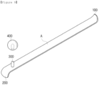
FIGS. 1 to 5 , and the acupressure body A is formed with a thin thickness, while having a predetermined width and length, and can be formed in the form similar to a 'back scratcher'. Further, when considering that the present invention is used using the principle of the lever, the acupressure body A is preferably made of a material that is robust and has some elasticity. - As shown in
FIGS. 1 to 5 , the acupressure body A has one end bent in one direction to form a firstpressing part 100. At this time, the firstpressing part 100 is formed to achieve a direction orthogonal to a longitudinal direction of the acupressure body A or a direction close to a direction orthogonal to the longitudinal direction of the acupressure body A so that the acupuncture point can be pressed through the tip. In addition, although a portion between the tip of the firstpressing part 100 and the acupressure body A may be bent in an angled shape, it is preferably bent in the form of a curved surface so that an injury can be prevented and solidity can be maintained when in use. - The first
pressing part 100 is formed to have a width that gradually reduces toward the tip. In addition, it is preferable that the tip of the firstpressing part 100 be formed to be blunt when viewed from the front and to be sharp when viewed from the side so as to be suitable for stimulating the acupuncture point. Therefore, the user can use the tool while pressing to position the acupuncture point to be subjected to acupressure on the lower side of the firstpressing part 100, fix the other end of the acupressure body A, and then stimulate the acupuncture point with the firstpressing part 100 using the principle of the lever. Accordingly, it is also possible to easily stimulate the acupuncture point such as convoluted point located deeply in the human body with a small force. - As a first example of use, as shown in
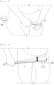
FIG. 6 , when a user wants to stimulate the acupuncture point of the left hand, the user places the left hand on the left leg in a seated state, and the acupressure body A crosses both legs to position the firstpressing part 100 on the left hand. After that, after the other end of the acupressure body A is axially fixed, the acupressure body A adjacent to the firstpressing part 100 is moved up and down with the right hand so that the firstpressing part 100 can stimulate the acupuncture point. - As a second example of use, as shown in
FIG. 7 , when the user wants to stimulate the acupuncture point of the left hand, the user places the left hand on the left leg in a seated state, and the acupressure body A is positioned under the right leg, at the same time, the firstpressing part 100 is positioned on the left hand. After that, while the other end of the acupressure body A is axially fixed by the right leg, the part of the acupressure body A adjacent to the firstpressing part 100 is moved up and down with the right hand so that the firstpressing part 100 can stimulate the acupuncture point. - As a third example of use, when the user wants to stimulate the acupuncture point of the left hand, the first
pressing part 100 is placed on the left hand while the acupressure body A is sandwiched between the legs while lying on the left side. Thereafter, after the other end of the acupressure body A is axially fixed, the acupressure body A portion adjacent to the firstpressing part 100 is grasped with the right hand, and the gripped right hand is repeatedly pressed with the right leg so that the firstpressing part 100 can stimulate the acupuncture point. - On the other hand, the acupressure body A can have a
spherical hitting ball 400 as shown inFIGS. 1 to 5 , and the user can use thehitting ball 400 to massage him as shown inFIG. 8 . Thehitting ball 400 can be provided at various positions on the acupressure body A, but is preferably provided at the other end of the acupressure body A to protrude in one direction. Thus, thehitting ball 400 protruding in one direction from the other end of the acupressure body A can be utilized for axially fixing the other end of the acupressure body A, when pressing the first pressingpart 100 using the principle of the lever. - As an example of utilization of the
hitting ball 400, as shown inFIG. 6 , thehitting ball 400 can be positioned outside adjacent to the right leg in the first example of use, and thehitting ball 400 can be positioned at a rear side adjacent to the left leg in the third example of use. Thehitting ball 400 positioned in this way is engaged with the adjacent legs to serve to axially fix the other end of the acupressure body A, and the firstpressing part 100 can be used more efficiently to stimulate the acupuncture point. - Such a
hitting ball 400 can be attached to the acupressure body A via an adhesive or the like. It is preferable that theball 400 be detachably attached to the acupressure body A in consideration of replacement with theball 400 or the like. - As an example, as shown in
FIG. 9 , a columnar thirdpressing part 300 may be formed to protrude from the other end of the acupressure body A, and the hittingball 400 can be detachably fitted into the thirdpressing part 300. It is preferable that the thirdpressing part 300 be formed to have a height lower than the protruding height of the hittingball 400 from the acupressure body A so that the hittingball 400 can be interference-fitted. - Further, the third
pressing part 300 can be formed so that the user separates the hittingball 400 and can stimulate the acupuncture point using the thirdpressing part 300. As an example, the thirdpressing unit 300 can be formed to have a blunt end. That is, as shown inFIG. 10 , the user can stimulate the acupuncture point using the thirdpressing part 300 formed in the same shape as a bullet, as in the first to third example of uses and the like. - As shown in
FIGS. 1 to 3 , the other end of the acupressure body A can be formed with a straight line, and it is possible to apply acupressure between the toes and the like using the straight other end of the acupressure body A. Also, as shown inFIGS. 4 and5 , the other end of the acupressure body A can be bent toward the other direction opposite to the firstpressing part 100 to form the secondpressing part 200. At this time, similarly to the firstpressing part 100, the secondpressing part 200 is formed to achieve a direction perpendicular to the longitudinal direction of the acupressure body A or a direction close to a direction perpendicular to the longitudinal direction of the acupressure body A so that the acupuncture point can pressed through the tip. Also, although the portion between the tip of the secondpressing part 200 and the acupressure body A can be bent in an angled shape, it is preferable to be bent in the form of a curved surface so that injury can be prevented and solidity can be maintained when use. - The tip of the second
pressing part 200 can be formed to have a gentler curvature than the tip of the firstpressing part 100, while being convex outward. That is, the secondpressing part 200 can press the acupuncture point in a wider range than the firstpressing part 100 when stimulating the acupuncture point. That is, as shown inFIG. 11 , the user can stimulate the acupuncture point using the secondpressing part 200, as in the first to third examples of use. - Through the present invention described above, the user can apply suitable stimulus to the acupuncture point, by selectively using any one of the first
pressing part 100, the secondpressing part 200, the thirdpressing part 300, and the hittingball 400, and thus can effectively stimulate various acupuncture points. - On the other hand, as shown in
FIG. 12 , the acupressure body A may further include a countingmember 500 capable of counting the number of times of pressing the acupuncture point by one of the firstpressing part 100, the secondpressing part 200, and the thirdpressing part 300 or the number of times of hitting the acupuncture point by the hittingball 400, and the countingmember 500 may be provided on one end side and/or the other end side of the acupressure body A, respectively. As a result, the user can easily grasp the number of times of pressing the acupuncture point and the number of times of hitting the body, and can gradually increase the number of times of pressing or hitting, or adjust the number of times of pressing or hitting every minute to perform more systematic acupressure. -
- A: Acupressure body
- 100: First pressing part
- 200: Second pressing part
- 300: Third pressing part
- 400: Hitting ball
Claims (5)
- An acupressure tool,wherein one end of a rod-shaped acupressure body (A) is bent toward one direction to form a first pressing part (100), andthe first pressing part (100) is formed to gradually decrease in width toward a tip, and is able to press an acupuncture point through the first pressing part (100) on the principle of a lever.
- The acupressure tool according to claim 1,
wherein a spherical hitting ball (400) is provided at the other end of the acupressure body (A) to protrude in one direction. - The acupressure tool according to claim 2,wherein a third pressing part (300) having a columnar shape and having a blunt tip is formed to protrude at the other end of the acupressure body (A), andthe hitting ball (400) is detachably fitted to the third pressing part (300).
- The acupressure tool according to claim 2,wherein the other end of the acupressure body (A) is bent toward the other direction to form a second pressing part (200), andthe second pressing part (200) is formed to have a tip which is convex outward, and have a gentler curvature than the tip of the first pressing part (100).
- The acupressure tool according to claim 1,
wherein the acupressure body (A) further comprises a counting member (500) capable of counting the number of times of pressing the acupuncture point through the first pressing part (100).
Applications Claiming Priority (2)
| Application Number | Priority Date | Filing Date | Title |
|---|---|---|---|
| KR1020200093231A KR102466847B1 (en) | 2020-07-27 | 2020-07-27 | Acupressure tool |
| PCT/KR2021/008468 WO2022025459A1 (en) | 2020-07-27 | 2021-07-05 | Acupressure tool |
Publications (2)
| Publication Number | Publication Date |
|---|---|
| EP4190302A1 true EP4190302A1 (en) | 2023-06-07 |
| EP4190302A4 EP4190302A4 (en) | 2024-08-07 |
Family
ID=80035656
Family Applications (1)
| Application Number | Title | Priority Date | Filing Date |
|---|---|---|---|
| EP21850671.5A Pending EP4190302A4 (en) | 2020-07-27 | 2021-07-05 | Acupressure tool |
Country Status (6)
| Country | Link |
|---|---|
| US (1) | US20230277414A1 (en) |
| EP (1) | EP4190302A4 (en) |
| JP (1) | JP2023536113A (en) |
| KR (1) | KR102466847B1 (en) |
| CN (1) | CN116209416A (en) |
| WO (1) | WO2022025459A1 (en) |
Family Cites Families (18)
| Publication number | Priority date | Publication date | Assignee | Title |
|---|---|---|---|---|
| US1612343A (en) * | 1925-06-09 | 1926-12-28 | Joseph S Amussen | Massaging implement |
| JPS4720088U (en) * | 1971-02-04 | 1972-11-07 | ||
| JPS56146939U (en) * | 1980-04-05 | 1981-11-05 | ||
| JPS5713031U (en) * | 1980-06-23 | 1982-01-23 | ||
| JPH0168040U (en) * | 1987-10-27 | 1989-05-01 | ||
| JP3007056U (en) * | 1994-04-28 | 1995-02-07 | 正範 廣田 | Shiatsu rod |
| JP3007909U (en) * | 1994-08-17 | 1995-02-28 | 正則 奥村 | Health device |
| JP2000033110A (en) * | 1998-07-17 | 2000-02-02 | Fumio Koshiba | Physical tool for finger-pressure therapy |
| JP3007909B1 (en) * | 1998-10-15 | 2000-02-14 | 財団法人 バイオインダストリー協会 | Method for measuring the abundance of specific strains in complex microbial systems |
| JP4173156B2 (en) * | 2005-10-21 | 2008-10-29 | 惠美子 鈴木 | Grandchild's hand |
| KR100680572B1 (en) * | 2005-11-03 | 2007-02-08 | 한상준 | A massager |
| KR20070096986A (en) * | 2007-06-15 | 2007-10-02 | 박정원 | Health mat |
| KR20130140291A (en) * | 2012-06-14 | 2013-12-24 | 하은민 | Acupressure |
| US20160136032A1 (en) * | 2014-11-14 | 2016-05-19 | Tara Dakides | Therapeutic massage device |
| JP3197518U (en) * | 2015-03-03 | 2015-05-21 | 悦雄 寺島 | Massage equipment |
| GB2537817B (en) * | 2015-04-20 | 2021-04-28 | Meiban Int Pte Ltd | Smart meridian tapper |
| KR101554119B1 (en) | 2015-06-16 | 2015-09-17 | 고승현 | leverage type finger pressing apparatus |
| JP2019037737A (en) * | 2017-12-12 | 2019-03-14 | 株式会社アリストレンディ | Curved article for pressing and/or rubbing outer surface of fleshy region of human body |
-
2020
- 2020-07-27 KR KR1020200093231A patent/KR102466847B1/en active IP Right Grant
-
2021
- 2021-07-05 WO PCT/KR2021/008468 patent/WO2022025459A1/en active Application Filing
- 2021-07-05 JP JP2023505904A patent/JP2023536113A/en active Pending
- 2021-07-05 US US18/016,458 patent/US20230277414A1/en active Pending
- 2021-07-05 EP EP21850671.5A patent/EP4190302A4/en active Pending
- 2021-07-05 CN CN202180060499.3A patent/CN116209416A/en active Pending
Also Published As
| Publication number | Publication date |
|---|---|
| US20230277414A1 (en) | 2023-09-07 |
| WO2022025459A1 (en) | 2022-02-03 |
| CN116209416A (en) | 2023-06-02 |
| JP2023536113A (en) | 2023-08-23 |
| KR20220013808A (en) | 2022-02-04 |
| KR102466847B1 (en) | 2022-11-11 |
| EP4190302A4 (en) | 2024-08-07 |
Similar Documents
| Publication | Publication Date | Title |
|---|---|---|
| US20040019305A1 (en) | Fitness stick | |
| US5766210A (en) | Massage device with multi-surface head and methods for its use | |
| KR100941568B1 (en) | Acupressure instrument for massage | |
| KR200333539Y1 (en) | A blood vessel massage for whole body | |
| EP4190302A1 (en) | Acupressure tool | |
| KR101612870B1 (en) | Massage Instrument | |
| US20180008505A1 (en) | "A.J.R. Tool" Massage Therapy Tool | |
| US20030114781A1 (en) | Hand-held massage tool | |
| JP7089717B2 (en) | Loosening stick | |
| KR200279986Y1 (en) | massage bar combined acupressure bar | |
| KR200431737Y1 (en) | Finger Pressure Device | |
| KR200483673Y1 (en) | Apparatus for acupressure | |
| JP3132233U (en) | Hand and foot reflex area and point stimulator | |
| JP3214583U (en) | Massage equipment | |
| KR200249551Y1 (en) | massage tool | |
| KR200212259Y1 (en) | Tools of finger-pressure therapy | |
| US20200375838A1 (en) | Systems and methods related to a myofascial-releasing treatment device | |
| JP3105545U (en) | Bar-type magnetic lubricator | |
| JPH11169428A (en) | Finger pressure helping tool | |
| KR200333542Y1 (en) | A Finger-Pressure Stick Having Niddle Stick and Projection Part | |
| KR200318373Y1 (en) | Acupressure bar | |
| JP2544382Y2 (en) | Shiatsu | |
| TWM644871U (en) | massager | |
| JP3019149U (en) | Shiatsu rod | |
| TWM575704U (en) | Grip type massager |
Legal Events
| Date | Code | Title | Description |
|---|---|---|---|
| STAA | Information on the status of an ep patent application or granted ep patent |
Free format text: STATUS: THE INTERNATIONAL PUBLICATION HAS BEEN MADE |
|
| PUAI | Public reference made under article 153(3) epc to a published international application that has entered the european phase |
Free format text: ORIGINAL CODE: 0009012 |
|
| STAA | Information on the status of an ep patent application or granted ep patent |
Free format text: STATUS: REQUEST FOR EXAMINATION WAS MADE |
|
| 17P | Request for examination filed |
Effective date: 20230222 |
|
| AK | Designated contracting states |
Kind code of ref document: A1 Designated state(s): AL AT BE BG CH CY CZ DE DK EE ES FI FR GB GR HR HU IE IS IT LI LT LU LV MC MK MT NL NO PL PT RO RS SE SI SK SM TR |
|
| DAV | Request for validation of the european patent (deleted) | ||
| DAX | Request for extension of the european patent (deleted) | ||
| A4 | Supplementary search report drawn up and despatched |
Effective date: 20240709 |
|
| RIC1 | Information provided on ipc code assigned before grant |
Ipc: A61H 15/00 20060101ALI20240703BHEP Ipc: A61H 39/04 20060101AFI20240703BHEP |