EP4189635B1 - Verfahren und vorrichtung zur unterwasser-abbildung - Google Patents
Verfahren und vorrichtung zur unterwasser-abbildung Download PDFInfo
- Publication number
- EP4189635B1 EP4189635B1 EP21746367.8A EP21746367A EP4189635B1 EP 4189635 B1 EP4189635 B1 EP 4189635B1 EP 21746367 A EP21746367 A EP 21746367A EP 4189635 B1 EP4189635 B1 EP 4189635B1
- Authority
- EP
- European Patent Office
- Prior art keywords
- polarization
- veil
- image
- backscattered
- angle
- Prior art date
- Legal status (The legal status is an assumption and is not a legal conclusion. Google has not performed a legal analysis and makes no representation as to the accuracy of the status listed.)
- Active
Links
Images

Classifications
-
- G—PHYSICS
- G03—PHOTOGRAPHY; CINEMATOGRAPHY; ANALOGOUS TECHNIQUES USING WAVES OTHER THAN OPTICAL WAVES; ELECTROGRAPHY; HOLOGRAPHY
- G03B—APPARATUS OR ARRANGEMENTS FOR TAKING PHOTOGRAPHS OR FOR PROJECTING OR VIEWING THEM; APPARATUS OR ARRANGEMENTS EMPLOYING ANALOGOUS TECHNIQUES USING WAVES OTHER THAN OPTICAL WAVES; ACCESSORIES THEREFOR
- G03B17/00—Details of cameras or camera bodies; Accessories therefor
- G03B17/02—Bodies
- G03B17/08—Waterproof bodies or housings
-
- G—PHYSICS
- G01—MEASURING; TESTING
- G01J—MEASUREMENT OF INTENSITY, VELOCITY, SPECTRAL CONTENT, POLARISATION, PHASE OR PULSE CHARACTERISTICS OF INFRARED, VISIBLE OR ULTRAVIOLET LIGHT; COLORIMETRY; RADIATION PYROMETRY
- G01J4/00—Measuring polarisation of light
- G01J4/04—Polarimeters using electric detection means
-
- G—PHYSICS
- G06—COMPUTING OR CALCULATING; COUNTING
- G06T—IMAGE DATA PROCESSING OR GENERATION, IN GENERAL
- G06T5/00—Image enhancement or restoration
- G06T5/50—Image enhancement or restoration using two or more images, e.g. averaging or subtraction
-
- G—PHYSICS
- G06—COMPUTING OR CALCULATING; COUNTING
- G06T—IMAGE DATA PROCESSING OR GENERATION, IN GENERAL
- G06T5/00—Image enhancement or restoration
- G06T5/73—Deblurring; Sharpening
-
- H—ELECTRICITY
- H04—ELECTRIC COMMUNICATION TECHNIQUE
- H04N—PICTORIAL COMMUNICATION, e.g. TELEVISION
- H04N23/00—Cameras or camera modules comprising electronic image sensors; Control thereof
- H04N23/10—Cameras or camera modules comprising electronic image sensors; Control thereof for generating image signals from different wavelengths
- H04N23/12—Cameras or camera modules comprising electronic image sensors; Control thereof for generating image signals from different wavelengths with one sensor only
-
- H—ELECTRICITY
- H04—ELECTRIC COMMUNICATION TECHNIQUE
- H04N—PICTORIAL COMMUNICATION, e.g. TELEVISION
- H04N23/00—Cameras or camera modules comprising electronic image sensors; Control thereof
- H04N23/60—Control of cameras or camera modules
- H04N23/66—Remote control of cameras or camera parts, e.g. by remote control devices
-
- H—ELECTRICITY
- H04—ELECTRIC COMMUNICATION TECHNIQUE
- H04N—PICTORIAL COMMUNICATION, e.g. TELEVISION
- H04N23/00—Cameras or camera modules comprising electronic image sensors; Control thereof
- H04N23/80—Camera processing pipelines; Components thereof
- H04N23/84—Camera processing pipelines; Components thereof for processing colour signals
-
- G—PHYSICS
- G06—COMPUTING OR CALCULATING; COUNTING
- G06T—IMAGE DATA PROCESSING OR GENERATION, IN GENERAL
- G06T2207/00—Indexing scheme for image analysis or image enhancement
- G06T2207/10—Image acquisition modality
- G06T2207/10141—Special mode during image acquisition
- G06T2207/10152—Varying illumination
-
- G—PHYSICS
- G06—COMPUTING OR CALCULATING; COUNTING
- G06T—IMAGE DATA PROCESSING OR GENERATION, IN GENERAL
- G06T2207/00—Indexing scheme for image analysis or image enhancement
- G06T2207/30—Subject of image; Context of image processing
- G06T2207/30248—Vehicle exterior or interior
- G06T2207/30252—Vehicle exterior; Vicinity of vehicle
Definitions
- the present invention relates to a method for polarized underwater imaging.
- the invention also relates to an underwater imaging device implementing such a method.
- the field of the invention is, in a non-limiting manner, that of underwater imaging. More particularly, but in a non-limiting manner, the field of the invention is that of underwater inspections in turbid waters.
- Polarimetric imaging is particularly known in underwater photography, using two different polarizations.
- systems implementing these methods require the manipulation of a polarization analyzer between the different image captures, as well as artificial lighting, polarized or not, of the underwater scene.
- the processing methods are relatively long, depending on the size of the acquired images.
- the known unveiling methods are not suitable for processing images in real time, for example for video.
- US 6,122,404 A uses a polarimetric image sensor that separately and simultaneously measures each of four separate Stokes polarization parameters of a visible light beam reflected from a scene.
- the sensor includes a compound prism assembly, the elements of which split the beam into four separate beams that are emitted from the prism assembly in different directions.
- Four separate polarimetric filters and imaging devices are positioned relative to the prism assembly to separately receive each of the four beams emitted from the prism assembly.
- each of the four imaging devices measures the light intensity reflected from the scene for each of the four Stokes parameters.
- the aim of the present invention is to provide a method and an underwater imaging device making it possible to overcome the drawbacks mentioned.
- An object of the present invention is to provide an underwater imaging method and device for obtaining clear and well-contrasted underwater images in real time in all types of water.
- the underwater imaging method improves the quality of images acquired underwater.
- the method implements polarimetric acquisition and processing of images, the processing being based on the analysis of the distribution of the polarization angle of the captured light. This analysis makes it possible to identify the light intensity coming from the diffusion by suspended particles and thus to eliminate it.
- the method according to the invention does not use any artificial lighting of the scene to be imaged. Only sunlight illuminates the scene. Sunlight is a so-called unpolarized light. However, according to Snell-Descartes and Maxwell's laws, the air/water interface has the effect of partially polarizing it. The polarization angle of the light depends on the position of the sun in the sky. In all cases, the light is sufficiently polarized after it passes the air/water interface. Also, the light is partially polarized when it is scattered by particles suspended in the water. The partial polarization, due to these two phenomena, of the scattered light makes it possible to apply the processing steps of the method according to the invention.
- the acquired image comprises at least four sub-images corresponding to at least four different polarizations.
- the sub-images are then acquired simultaneously, their acquisition requiring no manipulation or analyzer adjustment.
- Each sub-image completely represents the scene as the acquired image itself.
- the Stokes parameter calculation step and thus all other processing steps of the method according to the invention, is carried out from the light intensities of the pixels of the acquired image. This means that the entire image, with all the pixels, can be used to perform this calculation. Indeed, no choice of area or region of the image is made beforehand.
- the method according to the invention can be implemented in real time, in particular for video.
- submarine must be understood to mean “under water” in a general manner, the method and the device according to the invention being suitable for being implemented in an underwater environment, but of course also in a lake, a river, a stream, etc.
- the polarizations can be linear and correspond to 0°, 45°, 90° and 135°.
- two of the polarizations may be linear and the other two left and right circular polarizations.
- the method may further comprise a step of estimating the light intensity of the backscattering veil at infinity.
- the backscattering veil is entirely due to suspended particles, having a defined polarization.
- the light intensity at infinity therefore constitutes a reference for the state and nature (polarization, color) of the particle veil.
- the step of calculating the light intensity of the backscatter veil may comprise a step of calculating the average of the light intensities of the backscatter veil of all the sub-images.
- This step allows to have a restored image whose adjacent intensity values are not too different, thus avoiding digital artifacts.
- all image processing steps can be performed independently for each R, G and B color channel.
- the device is configured to implement the steps of the method according to the invention.
- the device is configured to be adaptable to a remotely operated underwater vehicle (ROV) or autonomous underwater vehicle .
- ROV remotely operated underwater vehicle
- autonomous underwater vehicle a remotely operated underwater vehicle
- This type of underwater vehicle can be used, for example, to inspect dams, tanks, boat hulls, pipelines, or more broadly all inspections of installations partially or completely submerged in water. They can also be used to carry out underwater work at depths or in places where humans cannot go.
- the sectors of application include: construction, dams, marine renewable energies, drilling, inspection, maintenance and repair of structures, telecommunications, the oil and gas industry, platform dismantling, the nuclear industry and defense.
- the device according to the invention can be directly worn by divers.
- a computer program comprising instructions which cause the underwater imaging device according to the invention to execute the steps of the underwater imaging method according to the invention.
- the invention relates to a computer-readable data carrier, on which the computer program according to the invention is recorded.
- FIG. 1 is a schematic representation of a non-limiting exemplary embodiment of an underwater imaging device that can be implemented within the framework of the present invention.
- the device can in particular be used to implement the method of the invention.
- Device 1 shown in the Figure 1 , comprises a digital camera 2 placed in a waterproof case 5 with an electronic processing card 4.
- the camera 2 comprises a lens 3.
- the camera 2 is arranged so that the lens 3 is positioned opposite a transparent porthole 6 of the case 5.
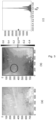
- Camera 2 is equipped with a polarimetric sensor, as shown in the Figure 2 .
- the sensor 7 is composed of a CMOS type matrix sensor, having a plurality of elementary sensors, and an analyzer matrix 8 having a plurality of analyzers 8a. Each elementary sensor is associated with an analyzer 8a.
- FIG. 2 also schematically shows part of the polarimetric sensor 7. As suggested in the Figure 2 by hatching, on each elementary sensor can be deposited a polarizing filter in the form of a network. A microlens can be deposited on each filter.
- the housing 5 further comprises a waterproof connector 9 for connecting a transmission cable to transmit the data from the electronic card 4 in real time to remote equipment, for example land or a boat, from which an ROV carrying the device 1 can be piloted using the camera 2.
- a waterproof connector 9 for connecting a transmission cable to transmit the data from the electronic card 4 in real time to remote equipment, for example land or a boat, from which an ROV carrying the device 1 can be piloted using the camera 2.
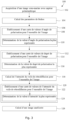
- FIG. 3 is a schematic representation of a non-limiting exemplary embodiment of an underwater imaging method according to the invention.
- Process 100 shown in the Figure 3 , comprises a step 102 of acquiring an underwater image.
- This step 102 can be carried out, for example, by a polarimetric image sensor as described with reference to the Figures 1 and 2
- the acquired image includes backscattering haze for at least some of the pixels.
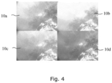
- the acquired image includes at least four sub-images corresponding to at least four different polarizations of the captured light.
- these polarizations are 0°, 45°, 90° and 135°.
- An example of four sub-images 10a, 10b, 10c, 10d with these polarizations is given in the Figure 4 .
- the intensity I received by the sensor is composed of the intensity reflected by the scene through the particle veil, noted D, and the intensity of the backscattering veil, that is to say that reflected by the suspended particles, noted A.
- the component A is partially polarized.
- I D + HAS
- L represents the intensity of the light without having been attenuated by the particle veil
- a inf the intensity of the backscattering veil for an imaginary object located at infinity
- t ( z ) the transmittance of the water.
- L I ⁇ HAS 1 ⁇ HAS / HAS inf .
- a step 104 Stokes parameters are calculated for each of the pixels of the acquired image from the captured light intensities I.
- the Stokes parameters are necessary to calculate the intensity A , the angle of polarization (AOP) ⁇ A and the degree of polarization (DOP) p A of the backscattering veil.
- the method according to the invention does not use artificial lighting, it is based solely on the polarization of incident natural light by the air/water passage and by suspended particles. These particles therefore return polarized light.
- step 106 of the method 100 the polarization angle ⁇ A of the backscattering veil is determined from the Stokes parameters.
- step 106 is performed as follows.
- the polarization angle of the particle veil is the most represented in the image, even if we are interested in the entire image and not only in a veil zone. Indeed, by comparing the histograms of polarization angles for the veil zone and for the entire image, for a plurality of images of different scenes, we can see that the maximum is approximately at the same angle value in both cases.
- a map of polarization angle values ⁇ from the Stokes parameters is established for the acquired image.
- a step 110 the most represented polarization angle value is determined. From the value map, a histogram of polarization angle values is calculated, and then the maximum value ⁇ A of the histogram is retrieved.
- FIG. 5 illustrates the steps for determining the polarization angle of the particle veil.
- the Figure 5(a) shows an image taken in water, unprocessed.
- the Figure 5(b) shows the map of polarization angle values present in the image.
- the circle corresponds to a so-called "veil" area, i.e., without an object to image.
- the Figure 5(c) shows the histogram of angle values for the entire scene as well as the maximum value, corresponding to angle ⁇ A .
- step 112 of the method 100 the degree of polarization p of the backscattering veil is determined from the Stokes parameters. This step 112 makes it possible to know the percentage of the intensity received by the sensor that is in the polarization state ⁇ A . According to the embodiment shown in the Figure 3 , step 112 is performed in the same manner as step 106 of determining the polarization angle.
- a map of polarization degree values p from the Stokes parameters is established for the acquired image.
- a step 116 the most represented polarization degree value p A is determined from the histogram of values.
- This embodiment makes it possible to further improve the quality of the image restoration and in particular to reduce color jumps on the restored image.
- this step 120 is carried out in the same manner as steps 106 and 112 of determining the angle and degree of polarization, respectively.
- a map of light intensity values is established for the entire acquired image.
- the value of the most represented light intensity is determined from the histogram of values.
- correction factors are introduced into the relation [Math5]. This makes it possible to avoid aberrations in the calculation of L if A is very close to Ainf.
- This coefficient is an adjustable parameter between 0 and 1.
- the value of 0.5 is chosen because it gives good results in tests in different types of water. Indeed, for automatic processing, it is not possible to determine the parameter ⁇ for each new image acquired. The value of 0.5 allows not to deteriorate the image processing while avoiding digital artifacts.
- HAS norm 1 2 HAS max HAS HAS inf .
- the result is a restored image that no longer has any defects or digital artifacts.
- the image processing steps 104-126 of the method 100 according to the invention are carried out independently for each color channel R, G and B of the acquired image.
- the underwater imaging method according to the present invention can be implemented on an electronic card of the FPGA ( field-programmable gate array ) type, for example composed of a Zynq 7020 from the company Xilinx.
- FPGA field-programmable gate array
- Such a card is very compact (70 mm x 45 mm) and can be easily embarked on an ROV, for example.
Landscapes
- Engineering & Computer Science (AREA)
- Physics & Mathematics (AREA)
- General Physics & Mathematics (AREA)
- Theoretical Computer Science (AREA)
- Multimedia (AREA)
- Signal Processing (AREA)
- Spectroscopy & Molecular Physics (AREA)
- Investigating Or Analysing Materials By Optical Means (AREA)
- Image Processing (AREA)
- Polarising Elements (AREA)
- Studio Devices (AREA)
Claims (12)
- Verfahren zur Unterwasserbildgebung (100), das die folgenden Schritte umfasst:∘ Erfassen (102) eines aus Pixeln gebildeten Bildes durch einen polarimetrischen Bildsensor (7), wobei das erfasste Bild einen Rückstreu-Schleier für mindestens einen Teil der Pixel umfasst, wobei das erfasste Bild mindestens vier Teilbilder (10a, 10b, 10c, 10d) umfasst, die gleichzeitig erfasst sind und mindestens vier verschiedenen Polarisationen entsprechen,∘ Berechnen (104) der Stokes-Parameter auf der Grundlage der Lichtintensitäten der Pixel des erfassten Bildes,dadurch gekennzeichnet, dass es die folgenden Schritte umfasst:∘ Bestimmen (106), basierend auf den Stokes-Parametern, eines Polarisationswinkels des Rückstreu-Schleiers,∘ Bestimmen (112), basierend auf den Stokes-Parametern, eines Polarisationsgrades des Rückstreu-Schleiers,∘ Berechnen (118) der Lichtintensität des Rückstreu-Schleiers basierend auf dem Polarisationswinkel und dem Polarisationsgrad des Rückstreu-Schleiers, und∘ Berechnen (126), basierend auf dem erfassten Bild und der Lichtintensität des Rückstreu-Schleiers, eines verbesserten Bildes,wobei das Verfahren mittels einer Vorrichtung zur Unterwasserbildgebung durchgeführt wird.
- Verfahren (100) nach dem vorhergehenden Anspruch, dadurch gekennzeichnet, dass die Polarisationen linear sind und 0°, 45°, 90° und 135° entsprechen.
- Verfahren (100) nach Anspruch 1 oder 2, dadurch gekennzeichnet, dass der Schritt (106) des Bestimmens eines Polarisationswinkels durchgeführt wird durch:- Erstellen (108) einer Karte von Polarisationswinkelwerten auf der Grundlage der Stokes-Parameter, und- Bestimmen (110) des am meisten repräsentierten Polarisationswinkelwertes, des sogenannten Polarisationswinkels des Schleiers, in dem erfassten Bild auf der Grundlage der Karte der Winkelwerte.
- Verfahren (100) nach einem der vorhergehenden Ansprüche, dadurch gekennzeichnet, dass der Schritt (112) des Bestimmens eines Polarisationsgrades durchgeführt wird durch:- Erstellen (114) einer Karte von Polarisationsgradwerten auf der Grundlage der Stokes-Parameter,- Bestimmen (116) des am meisten repräsentierten Polarisationsgradwertes, des sogenannten Polarisationsgrades des Schleiers, in dem erfassten Bild auf der Grundlage der Karte der Gradwerte.
- Verfahren (100) nach einem der vorhergehenden Ansprüche, dadurch gekennzeichnet, dass es weiterhin einen Schritt (120) des Schätzens der Lichtintensität des Rückstreu-Schleiers im Unendlichen umfasst.
- Verfahren (100) nach Anspruch 5, dadurch gekennzeichnet, dass der Schritt (120) des Schätzens der Lichtintensität des Rückstreu-Schleiers im Unendlichen durchgeführt wird durch:- Erstellen (122) einer Karte von Lichtintensitätswerten auf der Grundlage des Polarisationswinkels und des Polarisationsgrades des Rückstreu-Schleiers,- Bestimmen (124) des am stärksten vertretenen Intensitätswertes, der sogenannten Lichtintensität im Unendlichen, in dem erfassten Bild auf der Grundlage der Karte der Lichtintensitätswerte.
- Verfahren (100) nach einem der vorhergehenden Ansprüche, dadurch gekennzeichnet, dass der Schritt (118) des Berechnens der Lichtintensität des Rückstreu-Schleiers einen Schritt der Berechnung des Durchschnitts der Lichtintensitäten aller Teilbilder umfasst.
- Verfahren (100) nach einem der vorhergehenden Ansprüche, dadurch gekennzeichnet, dass alle Bildverarbeitungsschritte (104, 106, 112, 118) unabhängig für jeden Farbkanal R, G und B durchgeführt werden.
- Vorrichtung zur Unterwasserbildgebung (1), umfassend:- mindestens einen polarimetrischen Bildsensor (7) umfassend:∘ eine Vielzahl von Elementarsensoren,∘ eine Matrix (8) von Polarisationsanalysatoren, die so angeordnet sind, dass jeder Elementarsensor mit einem Analysator (8a) ausgestattet ist, wobei jeder Analysator (8a) gemäß einer von mindestens vier verschiedenen Polarisationen ausgerichtet ist, so dass die Ausrichtungen der Analysatoren (8a) auf homogene Weise über die Oberfläche des Sensors (7) verteilt sind,wobei der polarimetrische Bildsensor (7) so konfiguriert ist, dass er ein Bild erfasst, das mindestens vier Teilbilder (10a, 10b, 10c, 10d) umfasst, die gleichzeitig erfasst sind und den mindestens vier verschiedenen Polarisationen entsprechen; und- ein Bildverarbeitungsmodul (3);wobei die Vorrichtung (1) so konfiguriert ist, dass sie die Schritte des Verfahrens (100) nach einem der vorhergehenden Ansprüche ausführt.
- Vorrichtung (1) nach Anspruch 9, dadurch gekennzeichnet, dass sie so konfiguriert ist, dass sie an ein ferngesteuertes oder autonomes Unterwasserfahrzeug angebracht werden kann.
- Computerprogramm mit Befehlen, die die Vorrichtung zur Unterwasserbildgebung nach Anspruch 9 dazu veranlassen, die Schritte des Verfahrens zur Unterwasserbildgebung nach einem der Ansprüche 1 bis 8 auszuführen.
- Computerlesbarer Datenträger, auf dem das Computerprogramm nach Anspruch 11 aufgezeichnet ist.
Priority Applications (1)
| Application Number | Priority Date | Filing Date | Title |
|---|---|---|---|
| HRP20241533TT HRP20241533T1 (hr) | 2020-07-30 | 2021-07-08 | Postupak i uređaj za podvodno snimanje slika |
Applications Claiming Priority (2)
| Application Number | Priority Date | Filing Date | Title |
|---|---|---|---|
| FR2008098A FR3113162B1 (fr) | 2020-07-30 | 2020-07-30 | Procédé et dispositif d’imagerie sous-marine |
| PCT/EP2021/068976 WO2022022975A1 (fr) | 2020-07-30 | 2021-07-08 | Procede et dispositif d'imagerie sous-marine |
Publications (3)
| Publication Number | Publication Date |
|---|---|
| EP4189635A1 EP4189635A1 (de) | 2023-06-07 |
| EP4189635B1 true EP4189635B1 (de) | 2024-09-04 |
| EP4189635C0 EP4189635C0 (de) | 2024-09-04 |
Family
ID=73643020
Family Applications (1)
| Application Number | Title | Priority Date | Filing Date |
|---|---|---|---|
| EP21746367.8A Active EP4189635B1 (de) | 2020-07-30 | 2021-07-08 | Verfahren und vorrichtung zur unterwasser-abbildung |
Country Status (9)
| Country | Link |
|---|---|
| US (1) | US20230296965A1 (de) |
| EP (1) | EP4189635B1 (de) |
| JP (1) | JP2023541102A (de) |
| KR (1) | KR20230044425A (de) |
| CN (1) | CN116157827A (de) |
| FR (1) | FR3113162B1 (de) |
| HR (1) | HRP20241533T1 (de) |
| PL (1) | PL4189635T3 (de) |
| WO (1) | WO2022022975A1 (de) |
Families Citing this family (10)
| Publication number | Priority date | Publication date | Assignee | Title |
|---|---|---|---|---|
| CN115170498B (zh) * | 2022-06-30 | 2023-05-23 | 江苏科技大学 | 一种基于多指标优化的水下偏振成像方法 |
| CN114877898B (zh) * | 2022-07-11 | 2022-10-18 | 北京航空航天大学 | 基于水下偏振姿态与折射耦合反演的太阳动态跟踪方法 |
| CN115393216B (zh) * | 2022-08-25 | 2025-08-01 | 中国人民解放军国防科技大学 | 基于偏振特性与大气传输模型的图像去雾方法和装置 |
| CN116222581B (zh) * | 2023-05-10 | 2023-07-11 | 北京航空航天大学 | 一种基于水下光强拮抗差分的偏振抗干扰解算方法 |
| CN116596805B (zh) * | 2023-07-14 | 2023-09-29 | 山东大学 | 一种基于场景物体与大气光偏振态差异的偏振去雾方法 |
| CN116773457B (zh) * | 2023-08-18 | 2024-05-17 | 华东交通大学 | 基于Stokes参数的偏振测量方法、系统、设备和介质 |
| CN117939308B (zh) * | 2024-03-15 | 2024-06-18 | 季华实验室 | 偏振成像方法、装置、电子设备及存储介质 |
| CN118089594B (zh) * | 2024-04-28 | 2024-07-05 | 南京理工大学 | 基于散射噪声抑制的水下偏振条纹投影三维测量方法 |
| CN119595554B (zh) * | 2024-12-03 | 2025-09-23 | 西安交通大学 | 一种基于偏振共模双抑制的去散射成像方法及相关装置 |
| CN119469170A (zh) * | 2025-01-16 | 2025-02-18 | 中国人民解放军海军潜艇学院 | 一种基于水下偏振光检测的导航方法 |
Family Cites Families (27)
| Publication number | Priority date | Publication date | Assignee | Title |
|---|---|---|---|---|
| US4158506A (en) * | 1977-11-15 | 1979-06-19 | The United States Of America As Represented By The Secretary Of The Army | Automatic determination of the polarization state of nanosecond laser pulses |
| US5073025A (en) * | 1989-11-08 | 1991-12-17 | Rockwell International Corporation | Independent polarization state measurements sensor |
| US5416324A (en) * | 1993-06-11 | 1995-05-16 | Chun; Cornell S. L. | Optical imaging device with integrated polarizer |
| US6122404A (en) * | 1998-05-28 | 2000-09-19 | Trw Inc. | Visible stokes polarimetric imager |
| JP2002116085A (ja) * | 2000-10-05 | 2002-04-19 | Tetsuya Hamamoto | 偏光計測装置 |
| EP1738198A4 (de) * | 2004-02-13 | 2011-05-25 | Technion Res & Dev Foundation | Verbesserte unterwasserabbildung |
| US7582857B2 (en) * | 2006-04-18 | 2009-09-01 | The Trustees Of The University Of Pennsylvania | Sensor and polarimetric filters for real-time extraction of polarimetric information at the focal plane |
| EP2022008A4 (de) * | 2006-05-09 | 2012-02-01 | Technion Res & Dev Foundation | Abbildungssysteme und verfahren zur wiederherstellung der objektsichtbarkeit |
| US7630077B2 (en) * | 2006-10-13 | 2009-12-08 | University Of Massachusetts | System and method for imaging through an irregular water surface |
| US8305578B1 (en) * | 2009-05-01 | 2012-11-06 | Lockheed Martin Corporation | Imaging polarimeter |
| WO2010144866A2 (en) * | 2009-06-11 | 2010-12-16 | The Arizona Board Of Regents On Behalf Of The University Of Arizona | Microgrid imaging polarimeters with frequency domain reconstruction |
| US8411146B2 (en) * | 2009-09-04 | 2013-04-02 | Lockheed Martin Corporation | Single camera color and infrared polarimetric imaging |
| AU2011242408B2 (en) * | 2010-04-21 | 2016-12-15 | Commonwealth Scientific And Industrial Research Organisation | Shape and photometric invariants recovery from polarisation images |
| WO2013158975A1 (en) * | 2012-04-20 | 2013-10-24 | Washington University | Sensor for spectral-polarization imaging |
| US8885962B1 (en) * | 2012-07-23 | 2014-11-11 | Lockheed Martin Corporation | Realtime long range imaging scatter reduction |
| GB201307116D0 (en) * | 2013-04-18 | 2013-05-29 | Mbda Uk Ltd | Imaging apparatus and method |
| CN104216135A (zh) * | 2014-09-05 | 2014-12-17 | 西北工业大学 | 一种获取全偏振参数的微偏振片阵列、制备方法及其应用 |
| US9857226B2 (en) * | 2015-02-10 | 2018-01-02 | The United States Of America As Represented By The Secretary Of The Air Force | Microgrid arrangement for integrated imaging polarimeters |
| JP2018200401A (ja) * | 2017-05-26 | 2018-12-20 | 国立大学法人京都大学 | 光学機能素子、偏光解析装置及び、光学機能素子の製造方法 |
| JP2019052857A (ja) * | 2017-09-12 | 2019-04-04 | パナソニックIpマネジメント株式会社 | 撮像装置 |
| US11385104B2 (en) * | 2017-12-22 | 2022-07-12 | Arizona Board Of Regents On Behalf Of Arizona State University | On-chip polarization detection and polarimetric imaging |
| FR3076425B1 (fr) * | 2017-12-28 | 2020-01-31 | Forssea Robotics | Systeme d'imagerie sous-marine polarisee pour ameliorer la visibilite et la detection d'objet en eau turbide |
| CN109141638B (zh) * | 2018-07-25 | 2019-11-26 | 西安电子科技大学 | 一种自然光水下偏振成像方法 |
| US11405601B2 (en) * | 2019-09-17 | 2022-08-02 | Meta Platforms Technologies, Llc | Polarization capture device, system, and method |
| BR112022006617A2 (pt) * | 2019-10-07 | 2022-06-28 | Boston Polarimetrics Inc | Sistemas e métodos para detecção por sensor de normais à superfície com polarização |
| US11415791B1 (en) * | 2019-11-06 | 2022-08-16 | Ramona Optics Inc. | Snapshot polarization imaging with a micro-camera array microscope |
| US11127147B2 (en) * | 2019-12-10 | 2021-09-21 | GM Global Technology Operations LLC | Three-dimensional point cloud generation using a polarimetric camera in a drive assistance system equipped vehicle |
-
2020
- 2020-07-30 FR FR2008098A patent/FR3113162B1/fr active Active
-
2021
- 2021-07-08 US US18/006,635 patent/US20230296965A1/en active Pending
- 2021-07-08 PL PL21746367.8T patent/PL4189635T3/pl unknown
- 2021-07-08 HR HRP20241533TT patent/HRP20241533T1/hr unknown
- 2021-07-08 WO PCT/EP2021/068976 patent/WO2022022975A1/fr not_active Ceased
- 2021-07-08 EP EP21746367.8A patent/EP4189635B1/de active Active
- 2021-07-08 CN CN202180059021.9A patent/CN116157827A/zh active Pending
- 2021-07-08 KR KR1020237004188A patent/KR20230044425A/ko active Pending
- 2021-07-08 JP JP2023507232A patent/JP2023541102A/ja active Pending
Also Published As
| Publication number | Publication date |
|---|---|
| FR3113162A1 (fr) | 2022-02-04 |
| JP2023541102A (ja) | 2023-09-28 |
| KR20230044425A (ko) | 2023-04-04 |
| FR3113162B1 (fr) | 2022-07-29 |
| PL4189635T3 (pl) | 2024-11-25 |
| HRP20241533T1 (hr) | 2025-01-17 |
| US20230296965A1 (en) | 2023-09-21 |
| EP4189635A1 (de) | 2023-06-07 |
| EP4189635C0 (de) | 2024-09-04 |
| WO2022022975A1 (fr) | 2022-02-03 |
| CN116157827A (zh) | 2023-05-23 |
Similar Documents
| Publication | Publication Date | Title |
|---|---|---|
| EP4189635B1 (de) | Verfahren und vorrichtung zur unterwasser-abbildung | |
| EP2427752B1 (de) | Verfahren zur identifizierung einer szene aus mehrfachwellenlängenpolarisationsbildern | |
| EP2457379B1 (de) | Verfahren zur schätzung eines defekts in einem bilderfassungssystem und assoziierte systemen | |
| Lu et al. | Turbidity underwater image restoration using spectral properties and light compensation | |
| WO2010081982A1 (fr) | Controle de defauts optiques dans un systeme de capture d'images | |
| CA2961118A1 (fr) | Dispositif d'acquisition d'images bimode a photocathode | |
| EP0594712A1 (de) | Elektro-optischer detektor für reflexfreie unterwasseraufnahmen aus der luft | |
| WO2018163771A1 (ja) | 水質検査システム及び水質検査方法 | |
| CA2965323C (fr) | Procede de detection de pixels defectueux. | |
| EP3625758B1 (de) | Verfahren zur verarbeitung eines in anwesenheit von aerosolen und/oder wolken in der atmosphäre aufgenommenen optischen bildes | |
| WO2019129841A1 (fr) | Système d'imagerie sous-marine polarisée pour améliorer la visibilité et la détection d'objet en eau turbide | |
| FR3050300A1 (fr) | Procede et dispositif de detection automatique de zones de pollution sur une surface d'eau | |
| WO2016132068A1 (fr) | Procédé de détermination de la bathymétrie à partir d'images satellitaires optiques quasi synchrones | |
| FR2968879A1 (fr) | Procede de caracterisation de pixels d'un capteur d'image | |
| BE1015708A3 (fr) | Procede pour mesurer la hauteur de spheres ou d'hemispheres. | |
| Podobna et al. | Optical detection of marine mammals | |
| FR2966257A1 (fr) | Procede et dispositif de construction d'une image en relief a partir d'images en deux dimensions | |
| EP2520916A1 (de) | Multispektrales Scanteleskop mit Wellenfrontanalysemitteln. | |
| CA3119232C (fr) | Appareil et procede pour observer une scene comportant une cible | |
| Le Teurnier et al. | Enhancing the robustness of underwater dehazing by jointly using polarization and the dark channel prior | |
| FR2965616A1 (fr) | Procede d'imagerie d'une conduite longitudinale | |
| FR2945883A1 (fr) | Procede et systeme de detection de l'etat ouvert ou ferme des yeux d'un visage. | |
| FR2673794A1 (fr) | Dispositif de correction de defauts pour systemes d'imagerie. | |
| EP3797510B1 (de) | Panoramabeobachtungssystem für plattform | |
| EP4405648A1 (de) | Verfahren zur erfassung multispektraler bilder und panchromatischer miniaturbilder |
Legal Events
| Date | Code | Title | Description |
|---|---|---|---|
| REG | Reference to a national code |
Ref country code: HR Ref legal event code: TUEP Ref document number: P20241533T Country of ref document: HR |
|
| STAA | Information on the status of an ep patent application or granted ep patent |
Free format text: STATUS: UNKNOWN |
|
| STAA | Information on the status of an ep patent application or granted ep patent |
Free format text: STATUS: THE INTERNATIONAL PUBLICATION HAS BEEN MADE |
|
| PUAI | Public reference made under article 153(3) epc to a published international application that has entered the european phase |
Free format text: ORIGINAL CODE: 0009012 |
|
| STAA | Information on the status of an ep patent application or granted ep patent |
Free format text: STATUS: REQUEST FOR EXAMINATION WAS MADE |
|
| 17P | Request for examination filed |
Effective date: 20230202 |
|
| AK | Designated contracting states |
Kind code of ref document: A1 Designated state(s): AL AT BE BG CH CY CZ DE DK EE ES FI FR GB GR HR HU IE IS IT LI LT LU LV MC MK MT NL NO PL PT RO RS SE SI SK SM TR |
|
| DAV | Request for validation of the european patent (deleted) | ||
| DAX | Request for extension of the european patent (deleted) | ||
| REG | Reference to a national code |
Ref country code: DE Ref legal event code: R079 Ref document number: 602021018358 Country of ref document: DE Free format text: PREVIOUS MAIN CLASS: G06T0005000000 Ipc: G06T0005500000 Ref country code: DE Ref legal event code: R079 Free format text: PREVIOUS MAIN CLASS: G06T0005000000 Ipc: G06T0005500000 |
|
| GRAP | Despatch of communication of intention to grant a patent |
Free format text: ORIGINAL CODE: EPIDOSNIGR1 |
|
| STAA | Information on the status of an ep patent application or granted ep patent |
Free format text: STATUS: GRANT OF PATENT IS INTENDED |
|
| RIC1 | Information provided on ipc code assigned before grant |
Ipc: G06T 5/73 20240101ALI20240126BHEP Ipc: G06T 5/50 20060101AFI20240126BHEP |
|
| INTG | Intention to grant announced |
Effective date: 20240221 |
|
| GRAS | Grant fee paid |
Free format text: ORIGINAL CODE: EPIDOSNIGR3 |
|
| GRAA | (expected) grant |
Free format text: ORIGINAL CODE: 0009210 |
|
| STAA | Information on the status of an ep patent application or granted ep patent |
Free format text: STATUS: THE PATENT HAS BEEN GRANTED |
|
| AK | Designated contracting states |
Kind code of ref document: B1 Designated state(s): AL AT BE BG CH CY CZ DE DK EE ES FI FR GB GR HR HU IE IS IT LI LT LU LV MC MK MT NL NO PL PT RO RS SE SI SK SM TR |
|
| REG | Reference to a national code |
Ref country code: GB Ref legal event code: FG4D Free format text: NOT ENGLISH |
|
| REG | Reference to a national code |
Ref country code: CH Ref legal event code: EP |
|
| REG | Reference to a national code |
Ref country code: IE Ref legal event code: FG4D Free format text: LANGUAGE OF EP DOCUMENT: FRENCH |
|
| REG | Reference to a national code |
Ref country code: DE Ref legal event code: R096 Ref document number: 602021018358 Country of ref document: DE |
|
| U01 | Request for unitary effect filed |
Effective date: 20241003 |
|
| U07 | Unitary effect registered |
Designated state(s): AT BE BG DE DK EE FI FR IT LT LU LV MT NL PT RO SE SI Effective date: 20241025 |
|
| REG | Reference to a national code |
Ref country code: GR Ref legal event code: EP Ref document number: 20240402585 Country of ref document: GR Effective date: 20241209 |
|
| REG | Reference to a national code |
Ref country code: HR Ref legal event code: T1PR Ref document number: P20241533 Country of ref document: HR |
|
| PG25 | Lapsed in a contracting state [announced via postgrant information from national office to epo] |
Ref country code: ES Free format text: LAPSE BECAUSE OF FAILURE TO SUBMIT A TRANSLATION OF THE DESCRIPTION OR TO PAY THE FEE WITHIN THE PRESCRIBED TIME-LIMIT Effective date: 20240904 Ref country code: RS Free format text: LAPSE BECAUSE OF FAILURE TO SUBMIT A TRANSLATION OF THE DESCRIPTION OR TO PAY THE FEE WITHIN THE PRESCRIBED TIME-LIMIT Effective date: 20241204 |
|
| PG25 | Lapsed in a contracting state [announced via postgrant information from national office to epo] |
Ref country code: RS Free format text: LAPSE BECAUSE OF FAILURE TO SUBMIT A TRANSLATION OF THE DESCRIPTION OR TO PAY THE FEE WITHIN THE PRESCRIBED TIME-LIMIT Effective date: 20241204 Ref country code: ES Free format text: LAPSE BECAUSE OF FAILURE TO SUBMIT A TRANSLATION OF THE DESCRIPTION OR TO PAY THE FEE WITHIN THE PRESCRIBED TIME-LIMIT Effective date: 20240904 |
|
| PG25 | Lapsed in a contracting state [announced via postgrant information from national office to epo] |
Ref country code: SM Free format text: LAPSE BECAUSE OF FAILURE TO SUBMIT A TRANSLATION OF THE DESCRIPTION OR TO PAY THE FEE WITHIN THE PRESCRIBED TIME-LIMIT Effective date: 20240904 |
|
| PG25 | Lapsed in a contracting state [announced via postgrant information from national office to epo] |
Ref country code: CZ Free format text: LAPSE BECAUSE OF FAILURE TO SUBMIT A TRANSLATION OF THE DESCRIPTION OR TO PAY THE FEE WITHIN THE PRESCRIBED TIME-LIMIT Effective date: 20240904 |
|
| PG25 | Lapsed in a contracting state [announced via postgrant information from national office to epo] |
Ref country code: SK Free format text: LAPSE BECAUSE OF FAILURE TO SUBMIT A TRANSLATION OF THE DESCRIPTION OR TO PAY THE FEE WITHIN THE PRESCRIBED TIME-LIMIT Effective date: 20240904 |
|
| PLBE | No opposition filed within time limit |
Free format text: ORIGINAL CODE: 0009261 |
|
| STAA | Information on the status of an ep patent application or granted ep patent |
Free format text: STATUS: NO OPPOSITION FILED WITHIN TIME LIMIT |
|
| 26N | No opposition filed |
Effective date: 20250605 |
|
| REG | Reference to a national code |
Ref country code: HR Ref legal event code: ODRP Ref document number: P20241533 Country of ref document: HR Payment date: 20250723 Year of fee payment: 5 |
|
| U20 | Renewal fee for the european patent with unitary effect paid |
Year of fee payment: 5 Effective date: 20250725 |
|
| PGFP | Annual fee paid to national office [announced via postgrant information from national office to epo] |
Ref country code: MC Payment date: 20250725 Year of fee payment: 5 Ref country code: NO Payment date: 20250725 Year of fee payment: 5 Ref country code: GR Payment date: 20250725 Year of fee payment: 5 |
|
| PGFP | Annual fee paid to national office [announced via postgrant information from national office to epo] |
Ref country code: TR Payment date: 20250707 Year of fee payment: 5 Ref country code: PL Payment date: 20250703 Year of fee payment: 5 |
|
| PGFP | Annual fee paid to national office [announced via postgrant information from national office to epo] |
Ref country code: GB Payment date: 20250729 Year of fee payment: 5 |
|
| PGFP | Annual fee paid to national office [announced via postgrant information from national office to epo] |
Ref country code: HR Payment date: 20250723 Year of fee payment: 5 |
|
| PGFP | Annual fee paid to national office [announced via postgrant information from national office to epo] |
Ref country code: CH Payment date: 20250801 Year of fee payment: 5 |
|
| PGFP | Annual fee paid to national office [announced via postgrant information from national office to epo] |
Ref country code: IE Payment date: 20250725 Year of fee payment: 5 |
|
| PGFP | Annual fee paid to national office [announced via postgrant information from national office to epo] |
Ref country code: IS Payment date: 20250725 Year of fee payment: 5 |