EP4188765B1 - Verfahren zum starten eines verbrennungsmotors in einem antriebsstrang mit hybridisiertem doppelkupplungsgetriebe - Google Patents
Verfahren zum starten eines verbrennungsmotors in einem antriebsstrang mit hybridisiertem doppelkupplungsgetriebe Download PDFInfo
- Publication number
- EP4188765B1 EP4188765B1 EP21737615.1A EP21737615A EP4188765B1 EP 4188765 B1 EP4188765 B1 EP 4188765B1 EP 21737615 A EP21737615 A EP 21737615A EP 4188765 B1 EP4188765 B1 EP 4188765B1
- Authority
- EP
- European Patent Office
- Prior art keywords
- clutch
- combustion engine
- transmission
- internal combustion
- sub
- Prior art date
- Legal status (The legal status is an assumption and is not a legal conclusion. Google has not performed a legal analysis and makes no representation as to the accuracy of the status listed.)
- Active
Links
Images
Classifications
-
- B—PERFORMING OPERATIONS; TRANSPORTING
- B60—VEHICLES IN GENERAL
- B60W—CONJOINT CONTROL OF VEHICLE SUB-UNITS OF DIFFERENT TYPE OR DIFFERENT FUNCTION; CONTROL SYSTEMS SPECIALLY ADAPTED FOR HYBRID VEHICLES; ROAD VEHICLE DRIVE CONTROL SYSTEMS FOR PURPOSES NOT RELATED TO THE CONTROL OF A PARTICULAR SUB-UNIT
- B60W10/00—Conjoint control of vehicle sub-units of different type or different function
- B60W10/10—Conjoint control of vehicle sub-units of different type or different function including control of change-speed gearings
- B60W10/11—Stepped gearings
- B60W10/113—Stepped gearings with two input flow paths, e.g. double clutch transmission selection of one of the torque flow paths by the corresponding input clutch
-
- B—PERFORMING OPERATIONS; TRANSPORTING
- B60—VEHICLES IN GENERAL
- B60K—ARRANGEMENT OR MOUNTING OF PROPULSION UNITS OR OF TRANSMISSIONS IN VEHICLES; ARRANGEMENT OR MOUNTING OF PLURAL DIVERSE PRIME-MOVERS IN VEHICLES; AUXILIARY DRIVES FOR VEHICLES; INSTRUMENTATION OR DASHBOARDS FOR VEHICLES; ARRANGEMENTS IN CONNECTION WITH COOLING, AIR INTAKE, GAS EXHAUST OR FUEL SUPPLY OF PROPULSION UNITS IN VEHICLES
- B60K6/00—Arrangement or mounting of plural diverse prime-movers for mutual or common propulsion, e.g. hybrid propulsion systems comprising electric motors and internal combustion engines
- B60K6/20—Arrangement or mounting of plural diverse prime-movers for mutual or common propulsion, e.g. hybrid propulsion systems comprising electric motors and internal combustion engines the prime-movers consisting of electric motors and internal combustion engines, e.g. HEVs
- B60K6/22—Arrangement or mounting of plural diverse prime-movers for mutual or common propulsion, e.g. hybrid propulsion systems comprising electric motors and internal combustion engines the prime-movers consisting of electric motors and internal combustion engines, e.g. HEVs characterised by apparatus, components or means specially adapted for HEVs
- B60K6/26—Arrangement or mounting of plural diverse prime-movers for mutual or common propulsion, e.g. hybrid propulsion systems comprising electric motors and internal combustion engines the prime-movers consisting of electric motors and internal combustion engines, e.g. HEVs characterised by apparatus, components or means specially adapted for HEVs characterised by the motors or the generators
-
- B—PERFORMING OPERATIONS; TRANSPORTING
- B60—VEHICLES IN GENERAL
- B60K—ARRANGEMENT OR MOUNTING OF PROPULSION UNITS OR OF TRANSMISSIONS IN VEHICLES; ARRANGEMENT OR MOUNTING OF PLURAL DIVERSE PRIME-MOVERS IN VEHICLES; AUXILIARY DRIVES FOR VEHICLES; INSTRUMENTATION OR DASHBOARDS FOR VEHICLES; ARRANGEMENTS IN CONNECTION WITH COOLING, AIR INTAKE, GAS EXHAUST OR FUEL SUPPLY OF PROPULSION UNITS IN VEHICLES
- B60K6/00—Arrangement or mounting of plural diverse prime-movers for mutual or common propulsion, e.g. hybrid propulsion systems comprising electric motors and internal combustion engines
- B60K6/20—Arrangement or mounting of plural diverse prime-movers for mutual or common propulsion, e.g. hybrid propulsion systems comprising electric motors and internal combustion engines the prime-movers consisting of electric motors and internal combustion engines, e.g. HEVs
- B60K6/22—Arrangement or mounting of plural diverse prime-movers for mutual or common propulsion, e.g. hybrid propulsion systems comprising electric motors and internal combustion engines the prime-movers consisting of electric motors and internal combustion engines, e.g. HEVs characterised by apparatus, components or means specially adapted for HEVs
- B60K6/38—Arrangement or mounting of plural diverse prime-movers for mutual or common propulsion, e.g. hybrid propulsion systems comprising electric motors and internal combustion engines the prime-movers consisting of electric motors and internal combustion engines, e.g. HEVs characterised by apparatus, components or means specially adapted for HEVs characterised by the driveline clutches
- B60K6/387—Actuated clutches, i.e. clutches engaged or disengaged by electric, hydraulic or mechanical actuating means
-
- B—PERFORMING OPERATIONS; TRANSPORTING
- B60—VEHICLES IN GENERAL
- B60K—ARRANGEMENT OR MOUNTING OF PROPULSION UNITS OR OF TRANSMISSIONS IN VEHICLES; ARRANGEMENT OR MOUNTING OF PLURAL DIVERSE PRIME-MOVERS IN VEHICLES; AUXILIARY DRIVES FOR VEHICLES; INSTRUMENTATION OR DASHBOARDS FOR VEHICLES; ARRANGEMENTS IN CONNECTION WITH COOLING, AIR INTAKE, GAS EXHAUST OR FUEL SUPPLY OF PROPULSION UNITS IN VEHICLES
- B60K6/00—Arrangement or mounting of plural diverse prime-movers for mutual or common propulsion, e.g. hybrid propulsion systems comprising electric motors and internal combustion engines
- B60K6/20—Arrangement or mounting of plural diverse prime-movers for mutual or common propulsion, e.g. hybrid propulsion systems comprising electric motors and internal combustion engines the prime-movers consisting of electric motors and internal combustion engines, e.g. HEVs
- B60K6/42—Arrangement or mounting of plural diverse prime-movers for mutual or common propulsion, e.g. hybrid propulsion systems comprising electric motors and internal combustion engines the prime-movers consisting of electric motors and internal combustion engines, e.g. HEVs characterised by the architecture of the hybrid electric vehicle
- B60K6/48—Parallel type
-
- B—PERFORMING OPERATIONS; TRANSPORTING
- B60—VEHICLES IN GENERAL
- B60K—ARRANGEMENT OR MOUNTING OF PROPULSION UNITS OR OF TRANSMISSIONS IN VEHICLES; ARRANGEMENT OR MOUNTING OF PLURAL DIVERSE PRIME-MOVERS IN VEHICLES; AUXILIARY DRIVES FOR VEHICLES; INSTRUMENTATION OR DASHBOARDS FOR VEHICLES; ARRANGEMENTS IN CONNECTION WITH COOLING, AIR INTAKE, GAS EXHAUST OR FUEL SUPPLY OF PROPULSION UNITS IN VEHICLES
- B60K6/00—Arrangement or mounting of plural diverse prime-movers for mutual or common propulsion, e.g. hybrid propulsion systems comprising electric motors and internal combustion engines
- B60K6/20—Arrangement or mounting of plural diverse prime-movers for mutual or common propulsion, e.g. hybrid propulsion systems comprising electric motors and internal combustion engines the prime-movers consisting of electric motors and internal combustion engines, e.g. HEVs
- B60K6/50—Architecture of the driveline characterised by arrangement or kind of transmission units
- B60K6/54—Transmission for changing ratio
- B60K6/547—Transmission for changing ratio the transmission being a stepped gearing
-
- B—PERFORMING OPERATIONS; TRANSPORTING
- B60—VEHICLES IN GENERAL
- B60W—CONJOINT CONTROL OF VEHICLE SUB-UNITS OF DIFFERENT TYPE OR DIFFERENT FUNCTION; CONTROL SYSTEMS SPECIALLY ADAPTED FOR HYBRID VEHICLES; ROAD VEHICLE DRIVE CONTROL SYSTEMS FOR PURPOSES NOT RELATED TO THE CONTROL OF A PARTICULAR SUB-UNIT
- B60W20/00—Control systems specially adapted for hybrid vehicles
- B60W20/40—Controlling the engagement or disengagement of prime movers, e.g. for transition between prime movers
-
- B—PERFORMING OPERATIONS; TRANSPORTING
- B60—VEHICLES IN GENERAL
- B60K—ARRANGEMENT OR MOUNTING OF PROPULSION UNITS OR OF TRANSMISSIONS IN VEHICLES; ARRANGEMENT OR MOUNTING OF PLURAL DIVERSE PRIME-MOVERS IN VEHICLES; AUXILIARY DRIVES FOR VEHICLES; INSTRUMENTATION OR DASHBOARDS FOR VEHICLES; ARRANGEMENTS IN CONNECTION WITH COOLING, AIR INTAKE, GAS EXHAUST OR FUEL SUPPLY OF PROPULSION UNITS IN VEHICLES
- B60K6/00—Arrangement or mounting of plural diverse prime-movers for mutual or common propulsion, e.g. hybrid propulsion systems comprising electric motors and internal combustion engines
- B60K6/20—Arrangement or mounting of plural diverse prime-movers for mutual or common propulsion, e.g. hybrid propulsion systems comprising electric motors and internal combustion engines the prime-movers consisting of electric motors and internal combustion engines, e.g. HEVs
- B60K6/22—Arrangement or mounting of plural diverse prime-movers for mutual or common propulsion, e.g. hybrid propulsion systems comprising electric motors and internal combustion engines the prime-movers consisting of electric motors and internal combustion engines, e.g. HEVs characterised by apparatus, components or means specially adapted for HEVs
- B60K6/26—Arrangement or mounting of plural diverse prime-movers for mutual or common propulsion, e.g. hybrid propulsion systems comprising electric motors and internal combustion engines the prime-movers consisting of electric motors and internal combustion engines, e.g. HEVs characterised by apparatus, components or means specially adapted for HEVs characterised by the motors or the generators
- B60K2006/268—Electric drive motor starts the engine, i.e. used as starter motor
-
- B—PERFORMING OPERATIONS; TRANSPORTING
- B60—VEHICLES IN GENERAL
- B60K—ARRANGEMENT OR MOUNTING OF PROPULSION UNITS OR OF TRANSMISSIONS IN VEHICLES; ARRANGEMENT OR MOUNTING OF PLURAL DIVERSE PRIME-MOVERS IN VEHICLES; AUXILIARY DRIVES FOR VEHICLES; INSTRUMENTATION OR DASHBOARDS FOR VEHICLES; ARRANGEMENTS IN CONNECTION WITH COOLING, AIR INTAKE, GAS EXHAUST OR FUEL SUPPLY OF PROPULSION UNITS IN VEHICLES
- B60K6/00—Arrangement or mounting of plural diverse prime-movers for mutual or common propulsion, e.g. hybrid propulsion systems comprising electric motors and internal combustion engines
- B60K6/20—Arrangement or mounting of plural diverse prime-movers for mutual or common propulsion, e.g. hybrid propulsion systems comprising electric motors and internal combustion engines the prime-movers consisting of electric motors and internal combustion engines, e.g. HEVs
- B60K6/42—Arrangement or mounting of plural diverse prime-movers for mutual or common propulsion, e.g. hybrid propulsion systems comprising electric motors and internal combustion engines the prime-movers consisting of electric motors and internal combustion engines, e.g. HEVs characterised by the architecture of the hybrid electric vehicle
- B60K6/48—Parallel type
- B60K2006/4816—Electric machine connected or connectable to gearbox internal shaft
-
- B—PERFORMING OPERATIONS; TRANSPORTING
- B60—VEHICLES IN GENERAL
- B60K—ARRANGEMENT OR MOUNTING OF PROPULSION UNITS OR OF TRANSMISSIONS IN VEHICLES; ARRANGEMENT OR MOUNTING OF PLURAL DIVERSE PRIME-MOVERS IN VEHICLES; AUXILIARY DRIVES FOR VEHICLES; INSTRUMENTATION OR DASHBOARDS FOR VEHICLES; ARRANGEMENTS IN CONNECTION WITH COOLING, AIR INTAKE, GAS EXHAUST OR FUEL SUPPLY OF PROPULSION UNITS IN VEHICLES
- B60K6/00—Arrangement or mounting of plural diverse prime-movers for mutual or common propulsion, e.g. hybrid propulsion systems comprising electric motors and internal combustion engines
- B60K6/20—Arrangement or mounting of plural diverse prime-movers for mutual or common propulsion, e.g. hybrid propulsion systems comprising electric motors and internal combustion engines the prime-movers consisting of electric motors and internal combustion engines, e.g. HEVs
- B60K6/42—Arrangement or mounting of plural diverse prime-movers for mutual or common propulsion, e.g. hybrid propulsion systems comprising electric motors and internal combustion engines the prime-movers consisting of electric motors and internal combustion engines, e.g. HEVs characterised by the architecture of the hybrid electric vehicle
- B60K6/48—Parallel type
- B60K2006/4825—Electric machine connected or connectable to gearbox input shaft
-
- B—PERFORMING OPERATIONS; TRANSPORTING
- B60—VEHICLES IN GENERAL
- B60W—CONJOINT CONTROL OF VEHICLE SUB-UNITS OF DIFFERENT TYPE OR DIFFERENT FUNCTION; CONTROL SYSTEMS SPECIALLY ADAPTED FOR HYBRID VEHICLES; ROAD VEHICLE DRIVE CONTROL SYSTEMS FOR PURPOSES NOT RELATED TO THE CONTROL OF A PARTICULAR SUB-UNIT
- B60W2510/00—Input parameters relating to a particular sub-units
- B60W2510/06—Combustion engines, Gas turbines
- B60W2510/0638—Engine speed
-
- B—PERFORMING OPERATIONS; TRANSPORTING
- B60—VEHICLES IN GENERAL
- B60W—CONJOINT CONTROL OF VEHICLE SUB-UNITS OF DIFFERENT TYPE OR DIFFERENT FUNCTION; CONTROL SYSTEMS SPECIALLY ADAPTED FOR HYBRID VEHICLES; ROAD VEHICLE DRIVE CONTROL SYSTEMS FOR PURPOSES NOT RELATED TO THE CONTROL OF A PARTICULAR SUB-UNIT
- B60W2510/00—Input parameters relating to a particular sub-units
- B60W2510/24—Energy storage means
- B60W2510/242—Energy storage means for electrical energy
- B60W2510/244—Charge state
-
- B—PERFORMING OPERATIONS; TRANSPORTING
- B60—VEHICLES IN GENERAL
- B60W—CONJOINT CONTROL OF VEHICLE SUB-UNITS OF DIFFERENT TYPE OR DIFFERENT FUNCTION; CONTROL SYSTEMS SPECIALLY ADAPTED FOR HYBRID VEHICLES; ROAD VEHICLE DRIVE CONTROL SYSTEMS FOR PURPOSES NOT RELATED TO THE CONTROL OF A PARTICULAR SUB-UNIT
- B60W2710/00—Output or target parameters relating to a particular sub-units
- B60W2710/02—Clutches
- B60W2710/021—Clutch engagement state
-
- B—PERFORMING OPERATIONS; TRANSPORTING
- B60—VEHICLES IN GENERAL
- B60W—CONJOINT CONTROL OF VEHICLE SUB-UNITS OF DIFFERENT TYPE OR DIFFERENT FUNCTION; CONTROL SYSTEMS SPECIALLY ADAPTED FOR HYBRID VEHICLES; ROAD VEHICLE DRIVE CONTROL SYSTEMS FOR PURPOSES NOT RELATED TO THE CONTROL OF A PARTICULAR SUB-UNIT
- B60W2710/00—Output or target parameters relating to a particular sub-units
- B60W2710/02—Clutches
- B60W2710/025—Clutch slip, i.e. difference between input and output speeds
-
- B—PERFORMING OPERATIONS; TRANSPORTING
- B60—VEHICLES IN GENERAL
- B60W—CONJOINT CONTROL OF VEHICLE SUB-UNITS OF DIFFERENT TYPE OR DIFFERENT FUNCTION; CONTROL SYSTEMS SPECIALLY ADAPTED FOR HYBRID VEHICLES; ROAD VEHICLE DRIVE CONTROL SYSTEMS FOR PURPOSES NOT RELATED TO THE CONTROL OF A PARTICULAR SUB-UNIT
- B60W2710/00—Output or target parameters relating to a particular sub-units
- B60W2710/06—Combustion engines, Gas turbines
- B60W2710/0644—Engine speed
-
- B—PERFORMING OPERATIONS; TRANSPORTING
- B60—VEHICLES IN GENERAL
- B60W—CONJOINT CONTROL OF VEHICLE SUB-UNITS OF DIFFERENT TYPE OR DIFFERENT FUNCTION; CONTROL SYSTEMS SPECIALLY ADAPTED FOR HYBRID VEHICLES; ROAD VEHICLE DRIVE CONTROL SYSTEMS FOR PURPOSES NOT RELATED TO THE CONTROL OF A PARTICULAR SUB-UNIT
- B60W2710/00—Output or target parameters relating to a particular sub-units
- B60W2710/08—Electric propulsion units
- B60W2710/083—Torque
-
- Y—GENERAL TAGGING OF NEW TECHNOLOGICAL DEVELOPMENTS; GENERAL TAGGING OF CROSS-SECTIONAL TECHNOLOGIES SPANNING OVER SEVERAL SECTIONS OF THE IPC; TECHNICAL SUBJECTS COVERED BY FORMER USPC CROSS-REFERENCE ART COLLECTIONS [XRACs] AND DIGESTS
- Y02—TECHNOLOGIES OR APPLICATIONS FOR MITIGATION OR ADAPTATION AGAINST CLIMATE CHANGE
- Y02T—CLIMATE CHANGE MITIGATION TECHNOLOGIES RELATED TO TRANSPORTATION
- Y02T10/00—Road transport of goods or passengers
- Y02T10/60—Other road transportation technologies with climate change mitigation effect
- Y02T10/62—Hybrid vehicles
Definitions
- the invention is based on a method for starting an internal combustion engine in a drive train with a hybridized dual-clutch transmission with two clutches and two partial transmissions, wherein an electric machine is connected to a partial transmission, and the internal combustion engine can be connected to both partial transmissions via at least two clutches, wherein the internal combustion engine is started starting from a purely electric driving mode via the one partial transmission and a first gear, wherein the drive power of the electric machine is transmitted to the non-electrified partial transmission via both clutches.
- Vehicles with a hybrid drive structure have an internal combustion engine and a second drive unit, which can be an electric motor, for example. This means that the drive torque can be generated by both drive units while the hybrid vehicle is in operation.
- a method for starting such a hybrid vehicle which has an electric machine and an internal combustion engine, wherein the electric machine is arranged on a second partial transmission of a dual clutch transmission having two partial transmissions, wherein when the hybrid vehicle is started with the electric machine, the internal combustion engine is started without the voltage applied to a drive train containing the dual clutch transmission being interrupted.
- a method for starting an internal combustion engine in a drive train with a hybridized dual-clutch transmission with two clutches and two partial transmissions is known, wherein an electric machine is connected to one electrified partial transmission, and the internal combustion engine can be connected to both partial transmissions via at least two clutches, wherein the internal combustion engine is started starting from a purely electric driving mode via the partial transmission and a first gear of the electrified partial transmission, wherein the drive power of the electric machine EM is transmitted to the non-electrified partial transmission via both clutches, and the electrified partial transmission is switched to neutral, while the non-electrified partial transmission is operated in a second gear.
- the first and second gear stages are understood to mean that a selection is made for a gear stage for each of the sub-transmissions, in the sense of a different gear stage. It does not mean that it corresponds to the first gear and the second gear of a transmission, according to a conventional arrangement of reduction in low gears to a transmission in high gears.
- an additional separating clutch is used to enable the combustion engine to operate independently of the hybrid drive system.
- a hybrid drive train with a dual clutch that also uses a separating clutch K0 between the combustion engine and the transmission. It describes a method for starting the combustion engine in which energy is transferred from the electric operation to the combustion engine via the separating clutch.
- a hybrid drive train with a separating element between the transmission with transmission clutches and the combustion engine is known, which is at least partially mounted within a clutch input hub of the dual clutch.
- the separating element has a synchronizer ring, so that the separating element is first opened frictionally and then positively in its end position.
- EN 10 2010 004 711 A1 shows a method for starting an internal combustion engine in a drive train with a hybridized dual-clutch transmission with two clutches and two partial transmissions, wherein an electric machine is connected to an electrified partial transmission, and the internal combustion engine can be connected to both partial transmissions via one clutch and via two, wherein starting from a purely electric driving mode, the internal combustion engine is started via the electrified partial transmission and an engaged gear in the electrified partial transmission, wherein the drive power of the electric machine is transmitted to the non-electrified partial transmission via both clutches, wherein the clutch of the electrified partial transmission is closed and the clutch of the non-electrified partial transmission is operated in slip and the clutch in frictional engagement, whereby the internal combustion engine is accelerated to constant speed and the clutch is closed frictionally after the two clutches for the partial transmissions have been at least partially closed.
- the object of the invention is to optimize the problem of starting an internal combustion engine at the lowest vehicle speeds as well as the further drive process with the help of a special sequence.
- the invention relates to a method for starting an internal combustion engine in a drive train with a hybridized dual-clutch transmission with two clutches and two partial transmissions, wherein an electric machine is connected to one electrified partial transmission, and the internal combustion engine can be connected to both partial transmissions via a separating element and at least two clutches, wherein the internal combustion engine is started starting from a purely electric driving mode via the partial transmission and a first gear of the electrified partial transmission, wherein clutch K0 has a locking synchronization and is integrated in a clutch hub.
- the first and second gear stages are understood to mean that a selection is made for a gear stage for each of the sub-transmissions, in the sense of a different gear stage. It does not mean that it corresponds to the first gear and the second gear of a transmission, according to a conventional arrangement of reduction in low gears to a transmission in high gears.
- a separating clutch designed as a locking synchronizer is used to enable the combustion engine to operate independently of the hybrid drive system.
- the speeds of the electric machine and the combustion engine can be adjusted independently of each other.
- the clutch of the electrified partial transmission is initially closed and the clutch of the non-electrified partial transmission is slipping in order to be able to adjust the speed of the electric machine and the combustion engine independently of the vehicle speed. This is a prerequisite for being able to tow the combustion engine to a minimum speed using the electric machine even at the lowest vehicle speeds while maintaining the output power.
- the separating element can tow the combustion engine to a speed in frictional operation. This speed must be above the ignition speed.
- the transmission control can open the separating element and combustion engine is given the go-ahead to start.
- the torque on the separating element is reduced to 0, causing the speed of the still unfired combustion engine to fall.
- the speed thresholds mentioned above must be selected in such a way that at the time of the go-ahead to start, the speed of the combustion engine is still above the ignition speed.
- the electric machine is positively connected to the output again by engaging a gear in the electrified partial transmission and by opening the separating clutches K1 and K2.
- the separating clutch can initially connect the combustion engine and the clutch primary side frictionally and then positively in the end position.
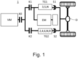
- the Figure 1 shows an example of a drive train 1 as is known from the prior art.
- An internal combustion engine VM drives a transmission 2 with two partial transmissions TG1 and TG2 and two clutches S1, S2, whereby the partial transmissions TG1 and TG2 can be decoupled from the internal combustion engine VM, or more precisely from the transmission input shaft, via clutches K1 and K2.
- a clutch K0 acts as a separating element and separates the internal combustion engine VM from the transmission 2.
- the drive train from both partial transmissions flows into a differential D.
- the electric machine EM is coupled to the partial transmission TG1.
- the method according to the invention starts with a driving state in which the electric machine EM alone drives the vehicle.
- the combustion engine VM is at a standstill and has not yet been ignited.
- the combustion engine VM is decoupled from the rest of the drive train via both opened clutches K1 and K2, as well as via the opened clutch K0.
- the partial transmission TG1 the purely electric drive with the electric machine EM Third gear is engaged.
- the clutch S1 is closed. This means that the drive energy flows from the electric machine EM via the partial transmission TG 1 with gear stage 3 to the differential D.
- the combustion engine VM is connected to the two transmission inputs via a clutch K0, each with input shaft 1 and input shaft 2.
- the clutch K0 is designed as a separating element with a locking synchronization. A design as shown in the state of the art cited above is preferred. Such a separating clutch integrated in the clutch hub is extremely space-saving. Such a spatially limited separating clutch K0 cannot be implemented using a friction clutch alone. In order to securely connect the combustion engine VM, a locking synchronization solution is selected.
- the locking synchronization can be designed in different ways.
- the locking synchronization must ensure synchronization between the front teeth of a component and a shift sleeve. As long as this synchronization is not achieved, it should block the shift sleeve from engaging the front teeth. If the speed is unequal, the synchronizer body gets in the way of the shift sleeve and prevents a positive connection.
- the combustion engine VM can be started under certain circumstances, e.g. at low vehicle speeds, using the separating element of the clutch K0. To do this, the clutch K0 is closed and initially transmits a torque using friction, which accelerates the combustion engine VM to constant speed. In the following phase, the combustion engine is positively coupled to the gearbox 2 by closing the clutch K0 to the end position.
- the phase between the friction and positive phases is called the free-flight phase, since there is briefly no mechanical connection between the two sides to be synchronized.
- a difference in speed can build up between the combustion engine VM and the connecting components, e.g. a clutch input hub.
- the torsional capacity of the claw gearing must be designed so that the combustion engine VM can be twisted against its drag torque. This must be taken into account in the design and has an impact on the design.
- the procedure begins with the request to start the combustion engine VM, which is the case, for example, when the battery charge level is low.
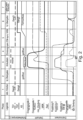
- the course of the gear setting is shown as the shift drum position over time. It is shown that the electric machine EM in the partial transmission TG1 is operated in the third gear, then switched to neutral, and then finally operated in the third gear.
- the partial transmission TG2 on the other hand, initially remains in the fourth gear and then operates in the second gear.
- the lowest graph in the top section describes the course of the clutch K0 over time. Until the first partial transmission TG1 is switched to neutral, the clutch K0 is opened and is closed during the neutral shift until frictional engagement and is opened again during the neutral shift. The positive engagement takes place after synchronization.
- the two transmission input shafts of the dual clutch transmission 2 rotate at different speeds n1 and n2.
- the course of the speeds over time is linear for the input shaft 2 of the second partial transmission TG2 until the gear change, whereas for the input shaft 1 of the first partial transmission TG1 the course is influenced by the clutch K0 and the ignition of the combustion engine, which will be described in detail later.
- the lowest speed curve represents the wheel speed, which is continuously linear.
- the constant course of the ignition speed is also shown.
- the process begins with purely electrical creep in phase 1 in the sub-gearbox TG1, with both clutches of the sub-gearboxes open. However, the input shaft speed of input shaft 1 is not sufficient to start the combustion engine.
- the torque transfer is prepared in order to transfer the power of the electric machine EM to the other sub-gearbox, in the example to the second sub-gearbox TG2.
- clutch K1 is first closed. Shortly before the third gear is disengaged in the partial transmission TG1, the torque of the electric machine EM is increased. Clutch K2 is also partially closed and operated in slip mode.
- clutch K2 reaches its target torque level and the torque of the electric machine EM is further increased.
- the separating element, clutch K0 is closed until frictional engagement.
- the speed of the electric machine EM is increased to such an extent that starting via the locking synchronization is possible and it can be ensured at all times that the locking condition on the locking synchronization is not violated.
- the torque of the combustion engine VM runs in the opposite direction to its drag torque.
- the clutch K0 is closed briefly to start the combustion engine VM.
- the speed of the electric machine EM must be selected so that the locking condition on the locking synchronization is never violated.
- phase 4 immediately after the combustion engine VM is ignited, the clutch K0 is fully opened.
- the combustion engine VM injects and is capable of running itself.
- the speed initially decreases slightly before ignition due to the opening of the clutch K0, then increases with the ignition and regulates itself to the setpoint.
- the torque of the electric machine EM is further reduced and the slipping clutch K2 is regulated to a low torque transmission.
- phase 5 the speed of the electric machine EM is synchronized to the third gear and this is engaged, both clutches K1 and K2 are opened. The clutch K0 is closed until the positive locking end position is reached.
- phase 6 the combustion engine VM regulates the idle speed while the torque on the combustion engine VM is increased. At the same time, the torque of the electric machine EM is reduced and the clutch K2 is closed.
- the batteries can be charged while crawling using the combustion engine VM.
- torque is transferred to the partial transmission TG1 and the electric machine EM via the output of the partial transmission TG2 and a closed clutch S1, and the electric machine EM is operated as a generator.
Landscapes
- Engineering & Computer Science (AREA)
- Transportation (AREA)
- Mechanical Engineering (AREA)
- Chemical & Material Sciences (AREA)
- Combustion & Propulsion (AREA)
- Automation & Control Theory (AREA)
- Hybrid Electric Vehicles (AREA)
- Control Of Transmission Device (AREA)
- Structure Of Transmissions (AREA)
- Electric Propulsion And Braking For Vehicles (AREA)
Description
- Die Erfindung geht aus von einem Verfahren zum Starten eines Verbrennungsmotors in einem Antriebsstrang mit hybridisiertem Doppelkupplungsgetriebe mit zwei Kupplungen und zwei Teilgetrieben, wobei eine elektrische Maschine an ein Teilgetriebe angebunden ist, und der Verbrennungsmotor über mindestens zwei Kupplungen mit beiden Teilgetrieben verbindbar ist, wobei ausgehend von einem rein elektrischen Fahrbetrieb über das eine Teilgetriebe und einer ersten Gangstufe der Verbrennungsmotor gestartet wird, wobei die Antriebsleistung der elektrischen Maschine über beide Kupplungen auf das nicht elektrifizierte Teilgetriebe übertragen wird.
- Fahrzeuge mit einer hybriden Antriebsstruktur weisen einen Verbrennungsmotor und ein zweites Antriebsaggregat auf, welches beispielsweise ein Elektromotor sein kann. So kann das Antriebsmoment während des Fahrbetriebes des Hybridfahrzeuges von beiden Antriebsaggregaten aufgebracht werden.
- Aus der
DE 10 2008 040 692 A1 ist ein Verfahren zum Anfahren eines solchen Hybridfahrzeuges bekannt, welches eine elektrische Maschine und ein Verbrennungsmotor aufweist, wobei die elektrische Maschine auf einem zweiten Teilgetriebe eines zwei Teilgetriebe aufweisenden Doppelkupplungsgetriebes angeordnet ist, wobei beim Anfahren des Hybridfahrzeuges mit der elektrischen Maschine der Verbrennungsmotor gestartet wird, ohne dass die an einem das Doppelkupplungsgetriebe enthaltenden Antriebsstrang anliegende Spannung unterbrochen wird. - Aus der
DE 10 2019 220 191 A1 ist ein Verfahren zum Starten eines Verbrennungsmotors in einem Antriebsstrang mit hybridisiertem Doppelkupplungsgetriebe mit zwei Kupplungen und zwei Teilgetrieben bekannt, wobei eine elektrische Maschine an das eine elektrifizierte Teilgetriebe angebunden ist, und der Verbrennungsmotor über mindesten zwei Kupplungen mit beiden Teilgetrieben verbindbar ist, wobei ausgehend von einem rein elektrischen Fahrbetrieb über das Teilgetriebe und einer ersten Gangstufe des elektrifizierten Teilgetriebes der Verbrennungsmotor gestartet wird, wobei die Antriebsleistung der elektrischen Maschine EM über beide Kupplungen auf das nicht elektrifizierte Teilgetriebe übertragen wird, und das elektrifizierte Teilgetriebe neutral geschaltet wird, während das nichtelektrifizierte Teilgetriebe in einer zweiten Gangstufe betrieben wird. - Dabei ist unter der ersten und der zweiten Gangstufe zu verstehen, dass eine Auswahl für eine Gangstufe für jedes der Teilgetriebe, im Sinnen einer anderen Gangstufe, getroffen wird. Es heißt nicht, dass es dem ersten Gang und dem zweiten Gang eines Getriebes entspräche, entsprechend einer konventionellen Anordnung von Untersetzung in niedrigen bis zu einer Übersetzung in hohen Gängen.
- In einer Version des Antriebsstrangs wird einen zusätzliche Trennkupplung verwendet, um den Verbrennungsmotor unabhängig vom Hybridantriebssystem betreiben zu können.
- Aus der
DE 10 2017 214 396 A1 ist ein Hybrid-Antriebsstrang mit Doppelkupplung bekannt, das auch eine Trennkupplung K0 zwischen Verbrennungsmotor und Getriebe verwendet. Darin wird ein Verfahren zum Starten des Verbrennungsmotors beschrieben, bei dem Energie über die Trennkupplung vom elektrischen Betrieb auf den Verbrennungsmotor übertragen wird. - Aus der unveröffentlichten
DE 10 2020 202 139 ist ein Hybridantriebsstrang mit einem ein Trennelement zwischen Getriebe mit Getriebekupplungen und Verbrennungsmotor bekannt, das zumindest teilweise innerhalb einer Kupplungseingangsnabe der Doppelkupplung angebracht ist. Das Trennelement weist einen Synchronring auf, so dass das Trennelement erst reibschlüssig und in seiner Endlage formschlüssig geöffnet ist. -
DE 10 2010 004 711 A1 zeigt ein Verfahren zum Starten eines Verbrennungsmotors in einem Antriebsstrang mit hybridisiertem Doppelkupplungsgetriebe mit zwei Kupplungen und zwei Teilgetrieben, wobei eine elektrische Maschine an ein elektrifiziertes Teilgetriebe angebunden ist, und der Verbrennungsmotor über eine Kupplung und über zwei mit beiden Teilgetrieben verbindbar ist, wobei ausgehend von einem rein elektrischen Fahrbetrieb über das elektrifizierte Teilgetriebe und eine eingelegte Gangstufe im elektrifizierten Teilgetriebe der Verbrennungsmotor gestartet wird, wobei die Antriebsleistung der elektrischen Maschine über beide Kupplungen auf das nicht elektrifizierte Teilgetriebe übertragen wird, wobei die Kupplung des elektrifizierten Teilgetriebes geschlossen ist und die Kupplung des nicht elektrifizierten Teilgetriebes im Schlupf und die Kupplung im Reibschluss betrieben wird, wodurch der Verbrennungsmotor auf Gleichlaufdrehzahl beschleunigt wird und die Kupplung reibschlüssig geschlossen wird, nachdem die beiden Kupplungen für die Teilgetriebe zumindest teilweise geschlossen wurden. - Es ist Aufgabe der Erfindung, das Problem des Startens eines Verbrennungsmotors bei kleinsten Fahrzeuggeschwindigkeiten sowie den weiteren Antriebsverlauf mit Hilfe eines speziellen Ablaufs zu optimieren.
- Die Erfindung betrifft ein Verfahren zum Starten eines Verbrennungsmotors in einem Antriebsstrang mit hybridisiertem Doppelkupplungsgetriebe mit zwei Kupplungen und zwei Teilgetrieben, wobei eine elektrische Maschine an das eine elektrifizierte Teilgetriebe angebunden ist, und der Verbrennungsmotor über eine Trennelement und mindesten zwei Kupplungen mit beiden Teilgetrieben verbindbar ist, wobei ausgehend von einem rein elektrischen Fahrbetrieb über das Teilgetriebe und einer ersten Gangstufe des elektrifizierten Teilgetriebes der Verbrennungsmotor gestartet wird, wobei Kupplung K0 eine Sperrsynchronisation aufweist und in einer Kupplungsnabe integriert ist.
- Die Aufgabe wird erfindungsgemäß mit einem Verfahren gelöst, welches die in Anspruch 1 angegebenen Merkmale aufweist.
- Dabei ist unter der ersten und der zweiten Gangstufe zu verstehen, dass eine Auswahl für eine Gangstufe für jedes der Teilgetriebe, im Sinnen einer anderen Gangstufe, getroffen wird. Es heißt nicht, dass es dem ersten Gang und dem zweiten Gang eines Getriebes entspräche, entsprechend einer konventionellen Anordnung von Untersetzung in niedrigen bis zu einer Übersetzung in hohen Gängen.
- Im Aufbau des Antriebsstrangs wird eine Trennkupplung als Sperrsynchronisierung ausgeführt verwendet, um den Verbrennungsmotor unabhängig vom Hybridantriebssystem betreiben zu können.
- Durch Verwendung der Trennkupplung kann das Einstellen der Drehzahlen von elektrischer Maschine und Verbrennungsmotor unabhängig voneinander erfolgen.
- Zum Starten des Verbrennungsmotors ist die Kupplung des elektrifizierten Teilgetriebes zunächst geschlossen und die Kupplung des nicht elektrifizierten Teilgetriebes im Schlupf, um die Drehzahl von elektrischer Maschine und Verbrennungsmotor unabhängig von der Fahrzeuggeschwindigkeit einstellen zu können. Dies ist Voraussetzung, um auch bei kleinsten Fahrzeuggeschwindigkeiten den Verbrennungsmotor auf eine Mindestdrehzahl mithilfe der elektrischen Maschine anschleppen zu können bei Aufrechterhaltung der Abtriebsleistung. Nachdem an der elektrischen Maschine eine definierte Drehzahlschwelle erreicht wurde, kann das Trennelement im reibschlüssigen Betrieb den Verbrennungsmotor auf eine Drehzahl anschleppen. Diese Drehzahl muss über der Zünddrehzahl liegt. Sobald diese Drehzahlschwelle erreicht wurde kann die Getriebesteuerung das Trennelement öffnen und dem Verbrennungsmotor die Startfreigabe erteilen. In der Phase des Öffnens wird das Drehmoment am Trennelement bis auf 0 reduziert, wodurch die Drehzahl des noch unbefeuerten Verbrennungsmotors fällt. Die zuvor erwähnten Drehzahlschwellen müssen derart gewählt werden, dass zum Zeitpunkt der Startfreigabe die Drehzahl am Verbrennungsmotor noch oberhalb der Zünddrehzahl liegt.
- Parallel zum Verbrennungsmotorstart wird die elektrische Maschine durch Einlegen eines Gangs im elektrifizierten Teilgetriebe und durch Öffnen der Trennkupplungen K1 und K2 wieder formschlüssigen an den Abtrieb angebunden.
- Nachdem beide Kupplungen K1 und K2 geöffnet wurden, kann die Trennkupplung den Verbrennungsmotor und die Kupplungsprimärseite zunächst reib- und in Endlage formschlüssig miteinander verbinden.
- Die Erfindung wird mit den Figuren und der nachfolgenden Beschreibung näher erläutert.
-
Figur 1 zeigt einen Antriebsstrang mit den unterschiedlichen Leistungswegen in einer beispielhaften Ausführungsform, -
Figur 2 zeigt ein Diagramm der Parameter des Antriebsstranges mit TG1 als elektrifizierten Getriebeteil. - Die
Figur 1 zeigt einen beispielhaften Antriebsstrang 1, wie er aus dem Stand der Technik bekannt ist. Ein Verbrennungsmotor VM treibt ein Getriebe 2 mit zwei Teilgetriebe TG1 und TG 2 und zwei Schaltkupplungen S1, S2, wobei die Teilgetriebe TG1 und TG2 über Kupplungen K1 und K2 vom Verbrennungsmotor VM, genauer von der Getriebeeingangswelle entkoppelbar sind. Zusätzlich trennt eine Kupplung K0 als Trennelement den Verbrennungsmotor VM vom Getriebe 2. - Getriebeausgangsseitig mündet der Antriebsstrang aus beiden Teilgetrieben an einem Differential D. Am Teilgetriebe TG1 ist die elektrische Maschine EM angekoppelt.
- Das erfindungsgemäße Verfahren startet mit einem Fahrzustand, in dem allein die elektrische Maschine EM das Fahrzeug antreibt. Der Verbrennungsmotor VM steht still und ist noch nicht gezündet. Der Verbrennungsmotor VM ist über beide geöffneten Kupplungen K1 und K2, sowie über die geöffnete Kupplung K0 vom Rest des Antriebsstranges abgekoppelt. Im Teilgetriebe TG1 ist für den rein elektrischen Antrieb mit der elektrischen Maschine EM der dritte Gang eingelegt. Die Schaltkupplung S1 ist dabei geschlossen. Damit fließt die Antriebsenergie von der elektrischen Maschine EM über das Teilgetriebe TG 1 mit der Gangstufe 3 auf das Differential D.
- Im Teilgetriebe TG2, das nicht mit der elektrischen Maschine EM direkt verbunden ist, ist während der rein elektrischen Fahrt der Gang der vierten Gangstufe eingelegt und die Kupplung K2, sowie die Schaltkupplung S2 geöffnet.
- Der Verbrennungsmotor VM ist über eine Kupplung K0 mit den beiden Getriebeeingängen jeweils mit der Eingangswelle 1 und der Eingangswelle 2 verbunden. Die Kupplung K0 ist als Trennelement mit einer Sperrsynchronisation ausgelegt. Bevorzugt ist dabei eine Auslegung wie im oben zitierten Stand der Technik dargestellt. Eine solche in der Kupplungsnabe integrierte Trennkupplung ist extrem bauraumsparend. Ein solche räumlich begrenzte Trennkupplung K0 ist nicht allein über eine Reibkupplung umzusetzen. Um den Verbrennungsmotor VM sicher anzubinden wird eine Sperrsynchronisationslösung gewählt.
- Die Sperrsynchronisation kann unterschiedlich ausgeführt sein. Die Sperrsynchronisation muss Gleichlauf zwischen der Vorverzahnung einer Komponente und einer Schaltmuffe herstellen. Solange dieser Gleichlauf nicht erreicht ist, soll sie der Schaltmuffe den Eingriff in die Vorverzahnung sperren. Bei ungleicher Drehzahl stellt sich der Synchronkörper der Schaltmuffe in den Weg und verhindert eine formschlüssige Verbindung.
- Das Starten des Verbrennungsmotors VM kann unter bestimmten Umständen, z. B bei kleinen Fahrzeuggeschwindigkeiten mithilfe des Trennelements, der Kupplung K0 erfolgen. Hierzu wird die Kupplung K0 geschlossen und überträgt zunächst reibschlüssig ein Drehmoment, wodurch der Verbrennungsmotor VM bis auf Gleichlaufdrehzahl beschleunigt wird. In der folgenden Phase wird der Verbrennungsmotor formschlüssig mit dem Getriebe 2 gekoppelt, indem die Kupplung K0 bis in Endlage geschlossen wird. Die Phase zwischen reibschlüssiger und formschlüssiger Phase wird Freiflugphase genannt, da kurzzeitig keine mechanische Verbindung zwischen den beiden zu synchronisierenden Seiten besteht.
- Erst wenn der Verbrennungsmotor VM formschlüssig mit dem Getriebe verbunden ist, die Kupplung K0 also voll geschlossen ist, darf dieser zünden und somit Drehmoment stellen.
- Während der Freiflugphase kann sich eine Differenz in der Drehzahl zwischen Verbrennungsmotor VM und der Verbindungskomponenten z.B. einer Kupplungseingangsnabe aufbauen.
- Im Resultat führt das zu einer hohen mechanischen Belastung beim Eindocken der - beispielhaften - Klauenverzahnung, was auch zu Geräuschen beim Verbinden führt.
- Die Verdrehkapazität der Klauenverzahnung muss so ausgelegt sein, dass der Verbrennungsmotor VM entgegen dessen Schleppmoment verdreht werden kann. Dies muss bei der Auslegung berücksichtigt werden und hat Auswirkungen auf das Design.
- Ist das Schleppmoment des Verbrennungsmotors größer als die Verdrehkapazität der Klauenverzahnung, kann ein sicheres Ankoppeln des Verbrennungsmotors nicht gewährleistet werden.
- Um diese Situation zu verbessern, wird das im Weiteren beschriebene Verfahren angewendet.
- Der Verlauf der Ansteuerung der Komponenten ist in
Figur 2 dargestellt. - In der
Figur 2 sind in unterschiedlichen Graphen der Ablauf des Starts des Verbrennungsmotors und das Verfahren zum Antreiben des Fahrzeugs mit der in derFigur 1 gezeigten Getriebevariante wiedergegeben. - Das Verfahren beginnt mit der Anforderung den Verbrennungsmotor VM zu starten, was beispielsweise bei einem niedrigen Batterieladungstand der Fall ist.
- Beginnend von oben ist in der
Figur 2 der Verlauf der Gangeinstellung als Schaltwalzenposition über der Zeit dargestellt. Dabei ist gezeigt, dass die elektrische Maschine EM im Teilgetriebe TG1 in der dritten Gangstufe betrieben wird, dann auf neutral geschaltet wird, um dann final in der dritten Gangstufe betrieben zu werden. Das Teilgetriebe TG2 dagegen verbleibt zunächst in der vierten Gangstufe, um dann in der zweiten Gangstufe betrieben zu werden. Der unterste Graph im obersten Abschnitt beschreibt den Verlauf der Kupplung K0 über der Zeit. Bis zur Neutralschaltung des ersten Teilgetriebes TG1 ist die Kupplung K0 geöffnet und wird während der Neutralschaltung bis zum Reibschluss geschlossen und noch während der Neutralschaltung wieder geöffnet. Der Formschluss erfolgt nach der Synchronisation. - In der mittleren Darstellung der der
Figur 2 sind die Verläufe der Drehzahlen der unterschiedlichen Komponenten des Antriebsstrangs über der Zeit dargestellt. - Die beiden Getriebeeingangswellen des Doppelkupplungsgetriebes 2 drehen mit unterschiedlichen Drehzahlen n1 und n2. Der Verlauf der Drehzahlen über der Zeit ist für die Eingangswelle 2 des zweiten Teilgetriebes TG2 linear bis zum Gangwechsel, für die Eingangswelle 1 des ersten Teilgetriebes TG1 wird der Verlauf dagegen durch die Kupplung K0 und das Zünden des Verbrennungsmotors beeinflusst, was später im Detail beschrieben wird.
- Weiterhin ist die Drehzahl des Verbrennungsmotors VM dargestellt.
- Die unterste Drehzahlkurve stellt die Raddrehzahl dar, die kontinuierlich linear ist. Weiterhin ist der konstante Verlauf der Zünddrehzahl dargestellt.
- Im unteren Bereich der der
Figur 2 sind die Drehmomente über der Zeit dargestellt. - Das Verfahren beginnt mit rein elektrischen Kriechen in Phase 1 im Teilgetriebe TG1, wobei beide Kupplungen der Teilgetriebe offen sind. Die Eingangswellendrehzahl der Eingangswelle 1 reicht aber nicht aus, um den Verbrennungsmotor zu starten.
- In Phase 2 wird die Drehmomentübergabe vorbereitet, um die Leistung der elektrischen Maschine EM auf das andere Teilgetriebe, im Beispiel auf das zweite Teilgetriebe TG2 zu übertragen.
- Dazu wird zunächst die Kupplung K1 geschlossen. Kurz vor dem Zeitpunkt, an dem der dritte Gang im Teilgetriebe TG1 ausgelegt wird, wird das Drehmoment der elektrischen Maschine EM erhöht. Die Kupplung K2 wird zusätzlich teilweise geschlossen und in Schlupf betrieben.
- In der Phase 3 erreicht die Kupplung K2 ihr angestrebtes Drehmomentniveau und das Drehmoment der elektrischen Maschine EM wird weiter erhöht. Gleichzeitig mit dem Ansteigen des Drehmoments der elektrischen Maschine EM wird das Trennelement, die Kupplung K0 bis zum Reibschluss geschlossen. Drehzahl der elektrischen Maschine EM wird so weit erhöht, dass ein Starten über die Sperrsynchronisation möglich ist und zu jedem Zeitpunkt sichergestellt werden kann, dass die Sperrbedingung an der Sperrsynchronisation nicht verletzt wird. Das Drehmoment des Verbrennungsmotors VM verläuft in dieser Phase des Reibschlusses der Kupplung K0 entgegen dessen Schleppmoment.
- Die Kupplung K0 wird kurzzeitig geschlossen, um den Verbrennungsmotor VM anzureißen. Die Drehzahl der elektrischen Maschine EM ist so zu wählen, dass zu keinem Zeitpunkt die Sperrbedingung an der Sperrsynchronisation verletzt wird.
- In der Phase 4 direkt nach der Zündung des Verbrennungsmotors VM ist die Kupplung K0 vollständig geöffnet. Der Verbrennungsmotor VM spritzt ein und ist selbstlauffähig. Die Drehzahl nimmt vor der Zündung durch das Öffnen der Kupplung K0 zunächst etwas ab, um dann mit der Zündung anzusteigen und sich auf dem Sollwert zu regeln. Das Drehmoment der elektrischen Maschine EM wird weiter zurückgenommen und die schlupfende Kupplung K2 auf eine geringe Drehmomentübertragung geregelt.
- In der Phase 5 wird die Drehzahl der elektrischen Maschine EM auf den dritten Gang synchronisiert und dieser eingelegt, beide Kupplungen K1 und K2 sind geöffnet. Die Kupplung K0 wird geschlossen bis die formschlüssige Endlage erreicht ist.
- In der Phase 6 regelt der Verbrennungsmotor VM Leerlaufdrehzahl ein, während das Drehmoment am Verbrennungsmotor VM erhöht wird. Gleichzeitig wird das Drehmoment der elektrischen Maschine EM reduziert und die Kupplung K2 geschlossen.
- Während der Phase 8 ist ein Laden der Batterien während des Kriechens mit dem Verbrennungsmotor VM möglich. Dazu wird über den Abtrieb des Teilgetriebes TG2 und einer geschlossenen Schaltkupplung S1 Drehmoment auf das Teilgetriebe TG1 und die elektrische Maschine EM gegeben und die elektrische Maschine EM als Generator betrieben.
Claims (1)
- Verfahren zum Starten eines Verbrennungsmotors (VM) in einem Antriebsstrang (1) mit hybridisiertem Doppelkupplungsgetriebe mit zwei Kupplungen (K1, K2) und zwei Teilgetrieben (TG1, TG2), wobei eine elektrische Maschine (EM) an ein elektrifiziertes Teilgetriebe angebunden ist, und der Verbrennungsmotor (VM) über eine Kupplung (K0) und über beide Kupplungen (K1, K2) mit beiden Teilgetrieben (TG1, TG2) verbindbar ist, wobei ausgehend von einem rein elektrischen Fahrbetrieb über das elektrifizierte Teilgetriebe und eine eingelegte Gangstufe im elektrifizierten Teilgetriebe der Verbrennungsmotor (VM) gestartet wird, wobei die Antriebsleistung der elektrischen Maschine (EM) über beide Kupplungen (TG1, TG2) auf das nicht elektrifizierte Teilgetriebe übertragen wird, wobei die Kupplung (K1, K2) des elektrifizierten Teilgetriebes geschlossen ist und die Kupplung (K1, K2) des nicht elektrifizierten Teilgetriebes im Schlupf und die Kupplung (K0) im Reibschluss betrieben wird, wodurch der Verbrennungsmotor (VM) auf Gleichlaufdrehzahl beschleunigt wird und die Kupplung (K0) reibschlüssig geschlossen wird, nachdem die beiden Kupplungen (K1, K2) für die Teilgetriebe (TG1, TG2) zumindest teilweise geschlossen wurden, dadurch gekennzeichnet, dass die Kupplung K0 eine Sperrsynchronisation aufweist und in einer Kupplungsnabe integriert ist und dass das Schließen gleichzeitig mit einem Anstieg des Drehmoments der elektrischen Maschine (EM) erfolgt und das Drehmoment der elektrischen Maschine (EM) mit dem Schließen, bzw. mit dem teilweisen Schließen der Kupplungen (K1, K2, K0) erhöht wird und die Kupplung (K0) geöffnet wird, nachdem die Drehzahl des Verbrennungsmotors (VM) einen Sollwert erreicht und die Kupplung (K0) formschlüssig geschlossen wird, nachdem beide Kupplungen (K1 K2) der Teilgetriebe (TG1, TG2) geöffnet sind.
Applications Claiming Priority (2)
| Application Number | Priority Date | Filing Date | Title |
|---|---|---|---|
| DE102020209452.7A DE102020209452A1 (de) | 2020-07-27 | 2020-07-27 | Verfahren zum Starten eines Verbrennungsmotors in einem Antriebsstrang mit hybridisiertem Doppelkupplungsgetriebe |
| PCT/EP2021/067724 WO2022022926A1 (de) | 2020-07-27 | 2021-06-28 | Verfahren zum starten eines verbrennungsmotors in einem antriebsstrang mit hybridisiertem doppelkupplungsgetriebe |
Publications (2)
| Publication Number | Publication Date |
|---|---|
| EP4188765A1 EP4188765A1 (de) | 2023-06-07 |
| EP4188765B1 true EP4188765B1 (de) | 2024-07-31 |
Family
ID=76796965
Family Applications (1)
| Application Number | Title | Priority Date | Filing Date |
|---|---|---|---|
| EP21737615.1A Active EP4188765B1 (de) | 2020-07-27 | 2021-06-28 | Verfahren zum starten eines verbrennungsmotors in einem antriebsstrang mit hybridisiertem doppelkupplungsgetriebe |
Country Status (4)
| Country | Link |
|---|---|
| EP (1) | EP4188765B1 (de) |
| CN (1) | CN115956040B (de) |
| DE (1) | DE102020209452A1 (de) |
| WO (1) | WO2022022926A1 (de) |
Families Citing this family (1)
| Publication number | Priority date | Publication date | Assignee | Title |
|---|---|---|---|---|
| DE102021202437B4 (de) | 2021-03-12 | 2024-05-02 | Magna Pt B.V. & Co. Kg | Verfahren zur Auswahl eines Ablaufs zum Starten eines Verbrennungsmotors in einem Antriebsstrang mit elektrifiziertem Doppelkupplungsgetriebe |
Family Cites Families (16)
| Publication number | Priority date | Publication date | Assignee | Title |
|---|---|---|---|---|
| DE102007052737A1 (de) * | 2006-12-05 | 2008-06-12 | Zf Friedrichshafen Ag | Verbrennungsmotor-Schleppstart eines Hybrid-Antriebstranges sowie Hybrid-Antriebsstrang |
| DE102007050659B4 (de) * | 2007-10-24 | 2023-08-03 | Zf Friedrichshafen Ag | Verfahren zum Betreiben eines Antriebsstrangs |
| DE102008040692A1 (de) | 2008-07-24 | 2010-01-28 | Robert Bosch Gmbh | Verfahren und Vorrichtung zum Anfahren eines Hybridfahrzeuges |
| DE102010004711C5 (de) * | 2010-01-11 | 2018-11-15 | GETRAG B.V. & Co. KG | Verfahren zum Ansteuern eines Hybrid-Antriebsstrangs |
| DE102010043355B4 (de) | 2010-11-04 | 2018-04-05 | Zf Friedrichshafen Ag | Verfahren zur Steuerung eines Hybridantriebsstrangs eines Kraftfahrzeugs |
| DE102010061827A1 (de) * | 2010-11-24 | 2012-05-24 | Zf Friedrichshafen Ag | Antriebsstrang und Verfahren zum Betreiben desselben |
| DE102011003080A1 (de) * | 2011-01-19 | 2012-07-19 | Robert Bosch Gmbh | Verfahren und Vorrichtung zum Betreiben einer Antriebsvorrichtung |
| DE102011018203B4 (de) * | 2011-04-12 | 2017-07-27 | Getrag Getriebe- Und Zahnradfabrik Hermann Hagenmeyer Gmbh & Cie Kg | Verfahren zum Betreiben eines Hybrid-Antriebsstranges und Steuereinrichtung zum Betreiben eines Hybrid-Antriebsstranges |
| DE102015219340A1 (de) * | 2015-10-07 | 2017-04-13 | Robert Bosch Gmbh | Verfahren und Vorrichtung zum Betreiben einer Antriebsvorrichtung, Antriebsvorrichtung |
| DE102016124828B3 (de) | 2016-12-19 | 2018-02-22 | Schaeffler Technologies AG & Co. KG | Hybrid-Antriebsstrang und Kraftfahrzeug mit Hybrid-Antriebsstrang |
| DE102017214396A1 (de) | 2017-08-18 | 2019-02-21 | Bayerische Motoren Werke Aktiengesellschaft | Hybridantriebsgetriebeeinheit sowie Verfahren zum Betreiben eines Fahrzeugs mit Hybridantrieb |
| DE102017216984A1 (de) * | 2017-09-25 | 2019-03-28 | GETRAG B.V. & Co. KG | Verfahren zur Ansteuerung eines Stufengetriebes und eines Antriebsstranges, sowie Steuereinrichtung und Antriebsstrang |
| DE102017130707A1 (de) * | 2017-12-20 | 2019-06-27 | GETRAG B.V. & Co. KG | Verfahren zum Betreiben eines Hybrid-Antriebsstranges sowie Hybrid-Antriebsstrang für ein Kraftfahrzeug |
| DE102018206115A1 (de) * | 2018-04-20 | 2019-10-24 | Magna Pt B.V. & Co. Kg | Verfahren zur Rückgewinnung von Energie des Verbrennungsmotors sowie Steuergerät zur Durchführung des Verfahrens |
| DE102019220191A1 (de) | 2019-07-31 | 2021-02-04 | Magna Pt B.V. & Co. Kg | Verfahren zum Starten eines Verbrennungsmotors in einem Antriebsstrang mit hybridisiertem Doppelkupplungsgetriebe |
| DE102020202139B4 (de) | 2020-02-19 | 2022-04-14 | Magna Pt B.V. & Co. Kg | Hybrid-Antriebsstrang für ein Kraftfahrzeug mit Trennelement |
-
2020
- 2020-07-27 DE DE102020209452.7A patent/DE102020209452A1/de not_active Ceased
-
2021
- 2021-06-28 EP EP21737615.1A patent/EP4188765B1/de active Active
- 2021-06-28 CN CN202180049945.0A patent/CN115956040B/zh active Active
- 2021-06-28 WO PCT/EP2021/067724 patent/WO2022022926A1/de not_active Ceased
Also Published As
| Publication number | Publication date |
|---|---|
| WO2022022926A1 (de) | 2022-02-03 |
| DE102020209452A1 (de) | 2022-01-27 |
| CN115956040A (zh) | 2023-04-11 |
| CN115956040B (zh) | 2026-01-06 |
| EP4188765A1 (de) | 2023-06-07 |
Similar Documents
| Publication | Publication Date | Title |
|---|---|---|
| EP2765338B1 (de) | Verfahren zum Betreiben eines hybridisierten Doppelkupplungsgetriebe-Antriebsstranges | |
| EP2920014B1 (de) | Verfahren zum betreiben einer antriebseinheit für ein hybridfahrzeug | |
| DE102012018416B4 (de) | Verfahren zum Ansteuern eines Hybridantriebsstranges | |
| EP2931545B1 (de) | Hybrid-antriebsstrang und verfahren zum betreiben eines solchen | |
| EP3668737B1 (de) | Hybridantriebsgetriebeeinheit sowie verfahren zum betreiben eines fahrzeugs mit hybridantrieb | |
| DE102010061826B4 (de) | Verfahren zur Beschleunigung der Entkopplung der die elektrische Maschine mit dem Getriebeeingang lösbar verbindenden Anfahrkupplung in einem Hybrid-Antriebsstrang eines Kraftfahrzeugs | |
| WO2013091971A1 (de) | Hybridantrieb eines kraftfahrzeugs und verfahren zum betreiben desselben | |
| EP2794317B1 (de) | Hybridantrieb eines kraftfahrzeugs und verfahren zum betreiben desselben | |
| EP3501870B1 (de) | Verfahren zum betreiben einer antriebseinrichtung für ein kraftfahrzeug sowie entsprechende antriebseinrichtung | |
| WO2006105929A1 (de) | Antriebsstrang eines fahrzeuges und verfahren zur steuerung eines antriebsstranges | |
| DE102006054405B4 (de) | Elektrodynamisches Anfahrelement und Verfahren zum Regeln eines elektrodynamischen Anfahrelements | |
| DE102012218121A1 (de) | Hybridantrieb eines Kraftfahrzeugs und Verfahren zum Betreiben desselben | |
| EP4188765B1 (de) | Verfahren zum starten eines verbrennungsmotors in einem antriebsstrang mit hybridisiertem doppelkupplungsgetriebe | |
| DE102019220191A1 (de) | Verfahren zum Starten eines Verbrennungsmotors in einem Antriebsstrang mit hybridisiertem Doppelkupplungsgetriebe | |
| DE102010028023B4 (de) | Verfahren zum Betreiben eines Antriebsstrangs | |
| WO2019185262A1 (de) | Verfahren zum betrieb eines antriebsstranges eines kraftfahrzeugs, und antriebs-strangmodul eines solchen kraftfahrzeugs | |
| EP3771583B1 (de) | Verfahren zum starten eines verbrennungsmotors in einem antriebsstrang mit hybridisiertem doppelkupplungsgetriebe | |
| WO2018065313A1 (de) | Verfahren zum anfahren eines kraftfahrzeuges | |
| DE102017220072A1 (de) | Verfahren beim Betrieb eines Hybridfahrzeugs | |
| EP4045348B1 (de) | Verfahren zum steuern eines hybridantriebsstrangs eines hybridkraftfahrzeugs | |
| EP3526094B1 (de) | Verfahren zum durchführen eines kriechladebetriebes und hybrid-antriebsstrang hierfür | |
| DE102011055085A1 (de) | Hybridantriebsstrang und Verfahren zum Steuern eines Hybridantriebsstranges | |
| DE102019212693B4 (de) | Verfahren zum Schalten eines Getriebes in einem Antriebsstrang | |
| DE102017213340B4 (de) | Getriebe für eine Hybridantriebsanordnung | |
| DE102016200420A1 (de) | Verfahren und Steuerungseinrichtung zum Betreiben eines Antriebsstrangs |
Legal Events
| Date | Code | Title | Description |
|---|---|---|---|
| STAA | Information on the status of an ep patent application or granted ep patent |
Free format text: STATUS: UNKNOWN |
|
| STAA | Information on the status of an ep patent application or granted ep patent |
Free format text: STATUS: THE INTERNATIONAL PUBLICATION HAS BEEN MADE |
|
| PUAI | Public reference made under article 153(3) epc to a published international application that has entered the european phase |
Free format text: ORIGINAL CODE: 0009012 |
|
| STAA | Information on the status of an ep patent application or granted ep patent |
Free format text: STATUS: REQUEST FOR EXAMINATION WAS MADE |
|
| 17P | Request for examination filed |
Effective date: 20230202 |
|
| AK | Designated contracting states |
Kind code of ref document: A1 Designated state(s): AL AT BE BG CH CY CZ DE DK EE ES FI FR GB GR HR HU IE IS IT LI LT LU LV MC MK MT NL NO PL PT RO RS SE SI SK SM TR |
|
| DAV | Request for validation of the european patent (deleted) | ||
| DAX | Request for extension of the european patent (deleted) | ||
| GRAP | Despatch of communication of intention to grant a patent |
Free format text: ORIGINAL CODE: EPIDOSNIGR1 |
|
| STAA | Information on the status of an ep patent application or granted ep patent |
Free format text: STATUS: GRANT OF PATENT IS INTENDED |
|
| INTG | Intention to grant announced |
Effective date: 20240220 |
|
| GRAS | Grant fee paid |
Free format text: ORIGINAL CODE: EPIDOSNIGR3 |
|
| GRAA | (expected) grant |
Free format text: ORIGINAL CODE: 0009210 |
|
| STAA | Information on the status of an ep patent application or granted ep patent |
Free format text: STATUS: THE PATENT HAS BEEN GRANTED |
|
| AK | Designated contracting states |
Kind code of ref document: B1 Designated state(s): AL AT BE BG CH CY CZ DE DK EE ES FI FR GB GR HR HU IE IS IT LI LT LU LV MC MK MT NL NO PL PT RO RS SE SI SK SM TR |
|
| REG | Reference to a national code |
Ref country code: CH Ref legal event code: EP Ref country code: GB Ref legal event code: FG4D Free format text: NOT ENGLISH |
|
| REG | Reference to a national code |
Ref country code: DE Ref legal event code: R096 Ref document number: 502021004603 Country of ref document: DE |
|
| REG | Reference to a national code |
Ref country code: IE Ref legal event code: FG4D Free format text: LANGUAGE OF EP DOCUMENT: GERMAN |
|
| REG | Reference to a national code |
Ref country code: LT Ref legal event code: MG9D |
|
| REG | Reference to a national code |
Ref country code: NL Ref legal event code: MP Effective date: 20240731 |
|
| PG25 | Lapsed in a contracting state [announced via postgrant information from national office to epo] |
Ref country code: PT Free format text: LAPSE BECAUSE OF FAILURE TO SUBMIT A TRANSLATION OF THE DESCRIPTION OR TO PAY THE FEE WITHIN THE PRESCRIBED TIME-LIMIT Effective date: 20241202 |
|
| PG25 | Lapsed in a contracting state [announced via postgrant information from national office to epo] |
Ref country code: PT Free format text: LAPSE BECAUSE OF FAILURE TO SUBMIT A TRANSLATION OF THE DESCRIPTION OR TO PAY THE FEE WITHIN THE PRESCRIBED TIME-LIMIT Effective date: 20241202 |
|
| PG25 | Lapsed in a contracting state [announced via postgrant information from national office to epo] |
Ref country code: NO Free format text: LAPSE BECAUSE OF FAILURE TO SUBMIT A TRANSLATION OF THE DESCRIPTION OR TO PAY THE FEE WITHIN THE PRESCRIBED TIME-LIMIT Effective date: 20241031 |
|
| PG25 | Lapsed in a contracting state [announced via postgrant information from national office to epo] |
Ref country code: NL Free format text: LAPSE BECAUSE OF FAILURE TO SUBMIT A TRANSLATION OF THE DESCRIPTION OR TO PAY THE FEE WITHIN THE PRESCRIBED TIME-LIMIT Effective date: 20240731 Ref country code: GR Free format text: LAPSE BECAUSE OF FAILURE TO SUBMIT A TRANSLATION OF THE DESCRIPTION OR TO PAY THE FEE WITHIN THE PRESCRIBED TIME-LIMIT Effective date: 20241101 Ref country code: FI Free format text: LAPSE BECAUSE OF FAILURE TO SUBMIT A TRANSLATION OF THE DESCRIPTION OR TO PAY THE FEE WITHIN THE PRESCRIBED TIME-LIMIT Effective date: 20240731 Ref country code: PL Free format text: LAPSE BECAUSE OF FAILURE TO SUBMIT A TRANSLATION OF THE DESCRIPTION OR TO PAY THE FEE WITHIN THE PRESCRIBED TIME-LIMIT Effective date: 20240731 |
|
| PG25 | Lapsed in a contracting state [announced via postgrant information from national office to epo] |
Ref country code: BG Free format text: LAPSE BECAUSE OF FAILURE TO SUBMIT A TRANSLATION OF THE DESCRIPTION OR TO PAY THE FEE WITHIN THE PRESCRIBED TIME-LIMIT Effective date: 20240731 |
|
| PG25 | Lapsed in a contracting state [announced via postgrant information from national office to epo] |
Ref country code: LV Free format text: LAPSE BECAUSE OF FAILURE TO SUBMIT A TRANSLATION OF THE DESCRIPTION OR TO PAY THE FEE WITHIN THE PRESCRIBED TIME-LIMIT Effective date: 20240731 |
|
| PG25 | Lapsed in a contracting state [announced via postgrant information from national office to epo] |
Ref country code: IS Free format text: LAPSE BECAUSE OF FAILURE TO SUBMIT A TRANSLATION OF THE DESCRIPTION OR TO PAY THE FEE WITHIN THE PRESCRIBED TIME-LIMIT Effective date: 20241130 |
|
| PG25 | Lapsed in a contracting state [announced via postgrant information from national office to epo] |
Ref country code: HR Free format text: LAPSE BECAUSE OF FAILURE TO SUBMIT A TRANSLATION OF THE DESCRIPTION OR TO PAY THE FEE WITHIN THE PRESCRIBED TIME-LIMIT Effective date: 20240731 |
|
| PG25 | Lapsed in a contracting state [announced via postgrant information from national office to epo] |
Ref country code: ES Free format text: LAPSE BECAUSE OF FAILURE TO SUBMIT A TRANSLATION OF THE DESCRIPTION OR TO PAY THE FEE WITHIN THE PRESCRIBED TIME-LIMIT Effective date: 20240731 Ref country code: RS Free format text: LAPSE BECAUSE OF FAILURE TO SUBMIT A TRANSLATION OF THE DESCRIPTION OR TO PAY THE FEE WITHIN THE PRESCRIBED TIME-LIMIT Effective date: 20241031 |
|
| PG25 | Lapsed in a contracting state [announced via postgrant information from national office to epo] |
Ref country code: RS Free format text: LAPSE BECAUSE OF FAILURE TO SUBMIT A TRANSLATION OF THE DESCRIPTION OR TO PAY THE FEE WITHIN THE PRESCRIBED TIME-LIMIT Effective date: 20241031 Ref country code: PL Free format text: LAPSE BECAUSE OF FAILURE TO SUBMIT A TRANSLATION OF THE DESCRIPTION OR TO PAY THE FEE WITHIN THE PRESCRIBED TIME-LIMIT Effective date: 20240731 Ref country code: NO Free format text: LAPSE BECAUSE OF FAILURE TO SUBMIT A TRANSLATION OF THE DESCRIPTION OR TO PAY THE FEE WITHIN THE PRESCRIBED TIME-LIMIT Effective date: 20241031 Ref country code: NL Free format text: LAPSE BECAUSE OF FAILURE TO SUBMIT A TRANSLATION OF THE DESCRIPTION OR TO PAY THE FEE WITHIN THE PRESCRIBED TIME-LIMIT Effective date: 20240731 Ref country code: LV Free format text: LAPSE BECAUSE OF FAILURE TO SUBMIT A TRANSLATION OF THE DESCRIPTION OR TO PAY THE FEE WITHIN THE PRESCRIBED TIME-LIMIT Effective date: 20240731 Ref country code: IS Free format text: LAPSE BECAUSE OF FAILURE TO SUBMIT A TRANSLATION OF THE DESCRIPTION OR TO PAY THE FEE WITHIN THE PRESCRIBED TIME-LIMIT Effective date: 20241130 Ref country code: HR Free format text: LAPSE BECAUSE OF FAILURE TO SUBMIT A TRANSLATION OF THE DESCRIPTION OR TO PAY THE FEE WITHIN THE PRESCRIBED TIME-LIMIT Effective date: 20240731 Ref country code: GR Free format text: LAPSE BECAUSE OF FAILURE TO SUBMIT A TRANSLATION OF THE DESCRIPTION OR TO PAY THE FEE WITHIN THE PRESCRIBED TIME-LIMIT Effective date: 20241101 Ref country code: FI Free format text: LAPSE BECAUSE OF FAILURE TO SUBMIT A TRANSLATION OF THE DESCRIPTION OR TO PAY THE FEE WITHIN THE PRESCRIBED TIME-LIMIT Effective date: 20240731 Ref country code: ES Free format text: LAPSE BECAUSE OF FAILURE TO SUBMIT A TRANSLATION OF THE DESCRIPTION OR TO PAY THE FEE WITHIN THE PRESCRIBED TIME-LIMIT Effective date: 20240731 Ref country code: BG Free format text: LAPSE BECAUSE OF FAILURE TO SUBMIT A TRANSLATION OF THE DESCRIPTION OR TO PAY THE FEE WITHIN THE PRESCRIBED TIME-LIMIT Effective date: 20240731 |
|
| PG25 | Lapsed in a contracting state [announced via postgrant information from national office to epo] |
Ref country code: RO Free format text: LAPSE BECAUSE OF FAILURE TO SUBMIT A TRANSLATION OF THE DESCRIPTION OR TO PAY THE FEE WITHIN THE PRESCRIBED TIME-LIMIT Effective date: 20240731 Ref country code: SM Free format text: LAPSE BECAUSE OF FAILURE TO SUBMIT A TRANSLATION OF THE DESCRIPTION OR TO PAY THE FEE WITHIN THE PRESCRIBED TIME-LIMIT Effective date: 20240731 Ref country code: DK Free format text: LAPSE BECAUSE OF FAILURE TO SUBMIT A TRANSLATION OF THE DESCRIPTION OR TO PAY THE FEE WITHIN THE PRESCRIBED TIME-LIMIT Effective date: 20240731 |
|
| PG25 | Lapsed in a contracting state [announced via postgrant information from national office to epo] |
Ref country code: EE Free format text: LAPSE BECAUSE OF FAILURE TO SUBMIT A TRANSLATION OF THE DESCRIPTION OR TO PAY THE FEE WITHIN THE PRESCRIBED TIME-LIMIT Effective date: 20240731 |
|
| PG25 | Lapsed in a contracting state [announced via postgrant information from national office to epo] |
Ref country code: CZ Free format text: LAPSE BECAUSE OF FAILURE TO SUBMIT A TRANSLATION OF THE DESCRIPTION OR TO PAY THE FEE WITHIN THE PRESCRIBED TIME-LIMIT Effective date: 20240731 |
|
| PG25 | Lapsed in a contracting state [announced via postgrant information from national office to epo] |
Ref country code: SK Free format text: LAPSE BECAUSE OF FAILURE TO SUBMIT A TRANSLATION OF THE DESCRIPTION OR TO PAY THE FEE WITHIN THE PRESCRIBED TIME-LIMIT Effective date: 20240731 Ref country code: IT Free format text: LAPSE BECAUSE OF FAILURE TO SUBMIT A TRANSLATION OF THE DESCRIPTION OR TO PAY THE FEE WITHIN THE PRESCRIBED TIME-LIMIT Effective date: 20240731 |
|
| REG | Reference to a national code |
Ref country code: DE Ref legal event code: R097 Ref document number: 502021004603 Country of ref document: DE |
|
| REG | Reference to a national code |
Ref country code: DE Ref legal event code: R082 Ref document number: 502021004603 Country of ref document: DE Representative=s name: EULER, MATTHIAS, DR., DE |
|
| PLBE | No opposition filed within time limit |
Free format text: ORIGINAL CODE: 0009261 |
|
| STAA | Information on the status of an ep patent application or granted ep patent |
Free format text: STATUS: NO OPPOSITION FILED WITHIN TIME LIMIT |
|
| 26N | No opposition filed |
Effective date: 20250501 |
|
| PGFP | Annual fee paid to national office [announced via postgrant information from national office to epo] |
Ref country code: DE Payment date: 20250618 Year of fee payment: 5 |
|
| PGFP | Annual fee paid to national office [announced via postgrant information from national office to epo] |
Ref country code: FR Payment date: 20250627 Year of fee payment: 5 |
|
| PGFP | Annual fee paid to national office [announced via postgrant information from national office to epo] |
Ref country code: AT Payment date: 20250721 Year of fee payment: 5 |
|
| PG25 | Lapsed in a contracting state [announced via postgrant information from national office to epo] |
Ref country code: SE Free format text: LAPSE BECAUSE OF FAILURE TO SUBMIT A TRANSLATION OF THE DESCRIPTION OR TO PAY THE FEE WITHIN THE PRESCRIBED TIME-LIMIT Effective date: 20240731 |
|
| REG | Reference to a national code |
Ref country code: DE Ref legal event code: R081 Ref document number: 502021004603 Country of ref document: DE Owner name: MAGNA PT B.V. & CO. KGAA, DE Free format text: FORMER OWNER: MAGNA PT B.V. & CO. KG, 74199 UNTERGRUPPENBACH, DE |
|
| REG | Reference to a national code |
Ref country code: CH Ref legal event code: H13 Free format text: ST27 STATUS EVENT CODE: U-0-0-H10-H13 (AS PROVIDED BY THE NATIONAL OFFICE) Effective date: 20260127 |
|
| PG25 | Lapsed in a contracting state [announced via postgrant information from national office to epo] |
Ref country code: MC Free format text: LAPSE BECAUSE OF FAILURE TO SUBMIT A TRANSLATION OF THE DESCRIPTION OR TO PAY THE FEE WITHIN THE PRESCRIBED TIME-LIMIT Effective date: 20240731 |
|
| PG25 | Lapsed in a contracting state [announced via postgrant information from national office to epo] |
Ref country code: LU Free format text: LAPSE BECAUSE OF NON-PAYMENT OF DUE FEES Effective date: 20250628 |
|
| GBPC | Gb: european patent ceased through non-payment of renewal fee |
Effective date: 20250628 |
|
| REG | Reference to a national code |
Ref country code: BE Ref legal event code: MM Effective date: 20250630 |
|
| PG25 | Lapsed in a contracting state [announced via postgrant information from national office to epo] |
Ref country code: GB Free format text: LAPSE BECAUSE OF NON-PAYMENT OF DUE FEES Effective date: 20250628 |
|
| PG25 | Lapsed in a contracting state [announced via postgrant information from national office to epo] |
Ref country code: IE Free format text: LAPSE BECAUSE OF NON-PAYMENT OF DUE FEES Effective date: 20250628 |
|
| PG25 | Lapsed in a contracting state [announced via postgrant information from national office to epo] |
Ref country code: BE Free format text: LAPSE BECAUSE OF NON-PAYMENT OF DUE FEES Effective date: 20250630 |
|
| PG25 | Lapsed in a contracting state [announced via postgrant information from national office to epo] |
Ref country code: CH Free format text: LAPSE BECAUSE OF NON-PAYMENT OF DUE FEES Effective date: 20250630 |