EP4187704A2 - Module de batterie, bloc-batterie et véhicule - Google Patents
Module de batterie, bloc-batterie et véhicule Download PDFInfo
- Publication number
- EP4187704A2 EP4187704A2 EP22752960.9A EP22752960A EP4187704A2 EP 4187704 A2 EP4187704 A2 EP 4187704A2 EP 22752960 A EP22752960 A EP 22752960A EP 4187704 A2 EP4187704 A2 EP 4187704A2
- Authority
- EP
- European Patent Office
- Prior art keywords
- bus bar
- electrode lead
- jig
- battery module
- welding
- Prior art date
- Legal status (The legal status is an assumption and is not a legal conclusion. Google has not performed a legal analysis and makes no representation as to the accuracy of the status listed.)
- Pending
Links
- 238000003466 welding Methods 0.000 claims abstract description 86
- 238000003780 insertion Methods 0.000 claims abstract description 24
- 230000037431 insertion Effects 0.000 claims abstract description 24
- 238000003825 pressing Methods 0.000 claims abstract description 20
- 238000004519 manufacturing process Methods 0.000 abstract description 5
- WHXSMMKQMYFTQS-UHFFFAOYSA-N Lithium Chemical compound [Li] WHXSMMKQMYFTQS-UHFFFAOYSA-N 0.000 description 6
- 229910052744 lithium Inorganic materials 0.000 description 6
- PXHVJJICTQNCMI-UHFFFAOYSA-N Nickel Chemical compound [Ni] PXHVJJICTQNCMI-UHFFFAOYSA-N 0.000 description 5
- 230000008878 coupling Effects 0.000 description 3
- 238000010168 coupling process Methods 0.000 description 3
- 238000005859 coupling reaction Methods 0.000 description 3
- 239000008151 electrolyte solution Substances 0.000 description 3
- 229910052751 metal Inorganic materials 0.000 description 3
- 239000002184 metal Substances 0.000 description 3
- 229910052782 aluminium Inorganic materials 0.000 description 2
- XAGFODPZIPBFFR-UHFFFAOYSA-N aluminium Chemical compound [Al] XAGFODPZIPBFFR-UHFFFAOYSA-N 0.000 description 2
- 238000000034 method Methods 0.000 description 2
- 239000007773 negative electrode material Substances 0.000 description 2
- 229910052759 nickel Inorganic materials 0.000 description 2
- 239000007774 positive electrode material Substances 0.000 description 2
- 229910000838 Al alloy Inorganic materials 0.000 description 1
- RYGMFSIKBFXOCR-UHFFFAOYSA-N Copper Chemical compound [Cu] RYGMFSIKBFXOCR-UHFFFAOYSA-N 0.000 description 1
- 229910000881 Cu alloy Inorganic materials 0.000 description 1
- 238000005452 bending Methods 0.000 description 1
- OJIJEKBXJYRIBZ-UHFFFAOYSA-N cadmium nickel Chemical compound [Ni].[Cd] OJIJEKBXJYRIBZ-UHFFFAOYSA-N 0.000 description 1
- 239000003575 carbonaceous material Substances 0.000 description 1
- 229910052802 copper Inorganic materials 0.000 description 1
- 239000010949 copper Substances 0.000 description 1
- 238000011161 development Methods 0.000 description 1
- 238000007599 discharging Methods 0.000 description 1
- 230000000694 effects Effects 0.000 description 1
- 238000004146 energy storage Methods 0.000 description 1
- 230000004927 fusion Effects 0.000 description 1
- 239000000463 material Substances 0.000 description 1
- 230000003446 memory effect Effects 0.000 description 1
- 238000012986 modification Methods 0.000 description 1
- 230000004048 modification Effects 0.000 description 1
- 229910000652 nickel hydride Inorganic materials 0.000 description 1
- QELJHCBNGDEXLD-UHFFFAOYSA-N nickel zinc Chemical compound [Ni].[Zn] QELJHCBNGDEXLD-UHFFFAOYSA-N 0.000 description 1
- 230000002093 peripheral effect Effects 0.000 description 1
- 238000011160 research Methods 0.000 description 1
- 230000000452 restraining effect Effects 0.000 description 1
- 238000007789 sealing Methods 0.000 description 1
- 239000000243 solution Substances 0.000 description 1
Images


Classifications
-
- H—ELECTRICITY
- H01—ELECTRIC ELEMENTS
- H01M—PROCESSES OR MEANS, e.g. BATTERIES, FOR THE DIRECT CONVERSION OF CHEMICAL ENERGY INTO ELECTRICAL ENERGY
- H01M50/00—Constructional details or processes of manufacture of the non-active parts of electrochemical cells other than fuel cells, e.g. hybrid cells
- H01M50/50—Current conducting connections for cells or batteries
- H01M50/502—Interconnectors for connecting terminals of adjacent batteries; Interconnectors for connecting cells outside a battery casing
-
- B—PERFORMING OPERATIONS; TRANSPORTING
- B23—MACHINE TOOLS; METAL-WORKING NOT OTHERWISE PROVIDED FOR
- B23K—SOLDERING OR UNSOLDERING; WELDING; CLADDING OR PLATING BY SOLDERING OR WELDING; CUTTING BY APPLYING HEAT LOCALLY, e.g. FLAME CUTTING; WORKING BY LASER BEAM
- B23K37/00—Auxiliary devices or processes, not specially adapted to a procedure covered by only one of the preceding main groups
- B23K37/04—Auxiliary devices or processes, not specially adapted to a procedure covered by only one of the preceding main groups for holding or positioning work
- B23K37/0426—Fixtures for other work
- B23K37/0435—Clamps
- B23K37/0443—Jigs
-
- H—ELECTRICITY
- H01—ELECTRIC ELEMENTS
- H01M—PROCESSES OR MEANS, e.g. BATTERIES, FOR THE DIRECT CONVERSION OF CHEMICAL ENERGY INTO ELECTRICAL ENERGY
- H01M50/00—Constructional details or processes of manufacture of the non-active parts of electrochemical cells other than fuel cells, e.g. hybrid cells
- H01M50/20—Mountings; Secondary casings or frames; Racks, modules or packs; Suspension devices; Shock absorbers; Transport or carrying devices; Holders
- H01M50/204—Racks, modules or packs for multiple batteries or multiple cells
- H01M50/207—Racks, modules or packs for multiple batteries or multiple cells characterised by their shape
- H01M50/209—Racks, modules or packs for multiple batteries or multiple cells characterised by their shape adapted for prismatic or rectangular cells
-
- H—ELECTRICITY
- H01—ELECTRIC ELEMENTS
- H01M—PROCESSES OR MEANS, e.g. BATTERIES, FOR THE DIRECT CONVERSION OF CHEMICAL ENERGY INTO ELECTRICAL ENERGY
- H01M50/00—Constructional details or processes of manufacture of the non-active parts of electrochemical cells other than fuel cells, e.g. hybrid cells
- H01M50/20—Mountings; Secondary casings or frames; Racks, modules or packs; Suspension devices; Shock absorbers; Transport or carrying devices; Holders
- H01M50/204—Racks, modules or packs for multiple batteries or multiple cells
- H01M50/207—Racks, modules or packs for multiple batteries or multiple cells characterised by their shape
- H01M50/211—Racks, modules or packs for multiple batteries or multiple cells characterised by their shape adapted for pouch cells
-
- H—ELECTRICITY
- H01—ELECTRIC ELEMENTS
- H01M—PROCESSES OR MEANS, e.g. BATTERIES, FOR THE DIRECT CONVERSION OF CHEMICAL ENERGY INTO ELECTRICAL ENERGY
- H01M50/00—Constructional details or processes of manufacture of the non-active parts of electrochemical cells other than fuel cells, e.g. hybrid cells
- H01M50/20—Mountings; Secondary casings or frames; Racks, modules or packs; Suspension devices; Shock absorbers; Transport or carrying devices; Holders
- H01M50/249—Mountings; Secondary casings or frames; Racks, modules or packs; Suspension devices; Shock absorbers; Transport or carrying devices; Holders specially adapted for aircraft or vehicles, e.g. cars or trains
-
- H—ELECTRICITY
- H01—ELECTRIC ELEMENTS
- H01M—PROCESSES OR MEANS, e.g. BATTERIES, FOR THE DIRECT CONVERSION OF CHEMICAL ENERGY INTO ELECTRICAL ENERGY
- H01M50/00—Constructional details or processes of manufacture of the non-active parts of electrochemical cells other than fuel cells, e.g. hybrid cells
- H01M50/50—Current conducting connections for cells or batteries
- H01M50/502—Interconnectors for connecting terminals of adjacent batteries; Interconnectors for connecting cells outside a battery casing
- H01M50/503—Interconnectors for connecting terminals of adjacent batteries; Interconnectors for connecting cells outside a battery casing characterised by the shape of the interconnectors
-
- H—ELECTRICITY
- H01—ELECTRIC ELEMENTS
- H01M—PROCESSES OR MEANS, e.g. BATTERIES, FOR THE DIRECT CONVERSION OF CHEMICAL ENERGY INTO ELECTRICAL ENERGY
- H01M50/00—Constructional details or processes of manufacture of the non-active parts of electrochemical cells other than fuel cells, e.g. hybrid cells
- H01M50/50—Current conducting connections for cells or batteries
- H01M50/502—Interconnectors for connecting terminals of adjacent batteries; Interconnectors for connecting cells outside a battery casing
- H01M50/507—Interconnectors for connecting terminals of adjacent batteries; Interconnectors for connecting cells outside a battery casing comprising an arrangement of two or more busbars within a container structure, e.g. busbar modules
-
- H—ELECTRICITY
- H01—ELECTRIC ELEMENTS
- H01M—PROCESSES OR MEANS, e.g. BATTERIES, FOR THE DIRECT CONVERSION OF CHEMICAL ENERGY INTO ELECTRICAL ENERGY
- H01M50/00—Constructional details or processes of manufacture of the non-active parts of electrochemical cells other than fuel cells, e.g. hybrid cells
- H01M50/50—Current conducting connections for cells or batteries
- H01M50/502—Interconnectors for connecting terminals of adjacent batteries; Interconnectors for connecting cells outside a battery casing
- H01M50/514—Methods for interconnecting adjacent batteries or cells
- H01M50/516—Methods for interconnecting adjacent batteries or cells by welding, soldering or brazing
-
- B—PERFORMING OPERATIONS; TRANSPORTING
- B23—MACHINE TOOLS; METAL-WORKING NOT OTHERWISE PROVIDED FOR
- B23K—SOLDERING OR UNSOLDERING; WELDING; CLADDING OR PLATING BY SOLDERING OR WELDING; CUTTING BY APPLYING HEAT LOCALLY, e.g. FLAME CUTTING; WORKING BY LASER BEAM
- B23K2101/00—Articles made by soldering, welding or cutting
- B23K2101/36—Electric or electronic devices
- B23K2101/38—Conductors
-
- B—PERFORMING OPERATIONS; TRANSPORTING
- B60—VEHICLES IN GENERAL
- B60L—PROPULSION OF ELECTRICALLY-PROPELLED VEHICLES; SUPPLYING ELECTRIC POWER FOR AUXILIARY EQUIPMENT OF ELECTRICALLY-PROPELLED VEHICLES; ELECTRODYNAMIC BRAKE SYSTEMS FOR VEHICLES IN GENERAL; MAGNETIC SUSPENSION OR LEVITATION FOR VEHICLES; MONITORING OPERATING VARIABLES OF ELECTRICALLY-PROPELLED VEHICLES; ELECTRIC SAFETY DEVICES FOR ELECTRICALLY-PROPELLED VEHICLES
- B60L50/00—Electric propulsion with power supplied within the vehicle
- B60L50/50—Electric propulsion with power supplied within the vehicle using propulsion power supplied by batteries or fuel cells
- B60L50/60—Electric propulsion with power supplied within the vehicle using propulsion power supplied by batteries or fuel cells using power supplied by batteries
- B60L50/64—Constructional details of batteries specially adapted for electric vehicles
-
- H—ELECTRICITY
- H01—ELECTRIC ELEMENTS
- H01M—PROCESSES OR MEANS, e.g. BATTERIES, FOR THE DIRECT CONVERSION OF CHEMICAL ENERGY INTO ELECTRICAL ENERGY
- H01M2220/00—Batteries for particular applications
- H01M2220/20—Batteries in motive systems, e.g. vehicle, ship, plane
-
- Y—GENERAL TAGGING OF NEW TECHNOLOGICAL DEVELOPMENTS; GENERAL TAGGING OF CROSS-SECTIONAL TECHNOLOGIES SPANNING OVER SEVERAL SECTIONS OF THE IPC; TECHNICAL SUBJECTS COVERED BY FORMER USPC CROSS-REFERENCE ART COLLECTIONS [XRACs] AND DIGESTS
- Y02—TECHNOLOGIES OR APPLICATIONS FOR MITIGATION OR ADAPTATION AGAINST CLIMATE CHANGE
- Y02E—REDUCTION OF GREENHOUSE GAS [GHG] EMISSIONS, RELATED TO ENERGY GENERATION, TRANSMISSION OR DISTRIBUTION
- Y02E60/00—Enabling technologies; Technologies with a potential or indirect contribution to GHG emissions mitigation
- Y02E60/10—Energy storage using batteries
Definitions
- the present disclosure relates to a battery module, a battery pack, and a vehicle, and more particularly, to a battery module in which the reliability of a welding portion between an electrode lead and a bus bar is improved and manufacturing costs are reduced, and a battery pack and a vehicle including the battery module.
- lithium secondary batteries are in the spotlight because they have almost no memory effect compared to nickel-based secondary batteries, and thus have advantages of free charge/discharge, very low self-discharge rate, and high energy density.
- a lithium secondary battery mainly uses a lithium-based oxide and a carbon material as a positive electrode active material and a negative electrode active material, respectively.
- the lithium secondary battery includes an electrode assembly in which a positive electrode plate and a negative electrode plate to which the positive electrode active material and the negative electrode active material are respectively applied are located with a separator therebetween, and a casing, that is, a battery case, for sealing and accommodating the electrode assembly along with an electrolytic solution.
- lithium secondary batteries may be classified into can-type secondary batteries in which an electrode assembly is received in a metal can, and pouch-type secondary batteries in which an electrode assembly is received in a pouch of an aluminum laminate sheet.
- a bus bar is applied to electrically connect stacked battery cells, and a plurality of electrode leads drawn out from the plurality of battery cells are bent, placed on the bus bar, and then welded.
- the electrode lead is pressed toward the bus bar by using a welding jig to be in close contact with the bus bar, and then welding is performed by emitting a laser to the electrode lead.
- the welding jig is supported only by the bus bar, and there are cases where the bus bar is not stably fixed on a bus bar frame. Accordingly, in the related art, while the bus bar supports the welding jig, the bus bar is likely to move by a pressing force of the welding jig or a position of the bus bar is likely to be changed. For this reason, a close contact state between the electrode lead and the bus bar is not maintained, thereby reducing welding reliability between the electrode lead and the bus bar.
- the bus bar needs to have a certain thickness sufficient to have a certain mechanical rigidity or more. Accordingly, there is a great limitation in reducing a thickness of the bus bar in the related art.
- the present disclosure is designed to solve the problems of the related art, and therefore the present disclosure is directed to providing a battery module in which welding reliability of a welding portion between an electrode lead and a bus bar is improved and manufacturing costs are reduced, and a battery pack and a vehicle including the battery module.
- a battery module including: a plurality of battery cells each including an electrode lead; a bus bar including a lead welding portion adhered to the electrode lead of each of the plurality of battery cells; and a bus bar frame including an insertion space into which at least a portion of the bus bar is inserted, and a jig support for supporting a welding jig configured to press the electrode lead, in a direction opposite to a pressing direction of the welding jig.
- the bus bar may further include a jig extending portion for supporting the welding jig in the direction opposite to the pressing direction of the welding jig.
- the bus bar may further include a frame insertion portion including an inward space into which the jig support is inserted.
- a portion of the bus bar may protrude outward, and a through-slit through which an end portion of the electrode lead passes may be formed in the protruding portion of the bus bar.
- a portion of the bus bar may protrude outward, and an insertion groove into which an end portion of the electrode lead is inserted may be formed in the protruding portion of the bus bar.
- the jig support may contact the electrode lead.
- a portion of the jig support may protrude outward, and a fixing slit through which an end portion of the electrode lead passes may be formed in the protruding portion of the jig support.
- a portion of the jig support may protrude outward, and a fixing groove into which an end portion of the electrode lead is inserted may be formed in the protruding portion of the jig support.
- a battery pack including at least one battery module as described above.
- a vehicle including at least one battery module as described above.
- a battery module includes a bus bar frame including an insertion space into which at least a portion of a bus bar is inserted and a jig support for supporting a welding jig
- a state where an electrode lead is in close contact with a lead welding portion of the bus bar may be stably maintained. That is, because the bus bar frame may stably limit the movement of the bus bar by accommodating a portion of the bus bar and may effectively restrain a pressing force of the welding jig by using the jig support, the bus bar may be prevented from being moved or deformed by a pressing force of the welding jig. Accordingly, welding reliability between the electrode lead and the bus bar may be effectively improved.
- FIG. 1 is a perspective view illustrating a battery module according to Embodiment 1 of the present disclosure.
- FIG. 2 is a perspective view illustrating the battery module of FIG. 1 and a welding jig.
- FIG. 3 is an exploded perspective view illustrating elements of the battery module according to Embodiment 1 of the present disclosure.
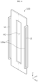
- FIG. 4 is a rear perspective view illustrating a bus bar of the battery module according to Embodiment 1 of the present disclosure.
- FIG. 5 is a partial horizontal cross-sectional view illustrating the battery module of FIG. 1 taken along line C-C'.
- an X-axis direction, a Y-axis direction, and a Z-axis direction in FIG. 1 respectively represent a right direction, a rear direction, and an up direction.
- a battery module 100 includes a plurality of battery cells 110, a bus bar 120, and a bus bar frame 130 including a jig support 131.
- the plurality of battery cells 110 may be arranged in a left-right direction (X-axis direction).
- the battery cells 110 may be pouch-type battery cells 110 each including an electrode assembly (not shown), an electrolytic solution (not shown), and a pouch 116 in which the electrode assembly and the electrolytic solution are accommodated.
- An outer peripheral portion of the pouch 116 may be sealed through thermal fusion.
- a cartridge 140 may be located between the plurality of battery cells 110.
- the cartridge 140 may be configured so that the plurality of battery cells 110 are uniformly arranged.
- a portion of the battery cell 110 may be accommodated in the cartridge 140.
- the cartridge 140 may include an electrically insulating plastic material.
- each of the plurality of battery cells 110 may include an electrode lead 111.
- the electrode lead 111 may be formed of an aluminum alloy or a copper alloy.
- the battery cell 110 may include a positive electrode lead 111a and a negative electrode lead 111b at both end portions in a front-back direction.
- the electrode lead 111 may protrude from the pouch 116 in the front-back direction.
- the electrode lead 111 may be bent in the left-right direction through, for example, a bending jig.
- the positive electrode lead 111a may be bent in the right direction.
- the negative electrode lead 11 1b may be bent in the left direction.
- the battery cell 110 is not necessarily limited to the pouch-type battery cell 110, and may be any of various battery cells 110 well known at the time of filling the present application.
- the battery module 100 may further include at least one bus bars 120 for electrically connecting the plurality of battery cells 110.
- the bus bar 120 may include a conductive metal.
- the conductive metal may be, for example, copper, aluminum, or nickel.
- the bus bar 120 may be electrically connected to a module terminal 150.
- an end portion of the bus bar 120 located at a rightmost position may be electrically connected to the module terminal 150.
- the bus bar 120 may include a lead-through hole H1 through which the electrode lead 111 passes, as shown in FIG. 3 .
- the electrode lead 111 may protrude to the outside through the lead-through hole H1.
- a protruding portion of the electrode lead 111 may be bent in the left direction or the right direction to contact an outer surface of the bus bar 120.
- the bus bars 120 may be electrically connected to the positive electrode lead 111a and the negative electrode lead 111b.
- the bus bar 120 may include a lead welding portion 121 adhered to the electrode lead 111 of each of the plurality of battery cells 110.
- the electrode lead 111 may be welded to an outer surface of the lead welding portion 121.
- a welding method is not limited to a specific method, and laser welding or ultrasonic welding may be used.
- the electrode lead 111 and the lead welding portion 121 of the bus bar 120 may be laser welded through a laser emitted by a laser welding device 20.
- At least one bus bar 120 may be mounted on an outer surface of the bus bar frame 130.
- the bus bar frame 130 may include a lead insertion hole H2 communicating with the lead-through hole H1 of the bus bar 120.
- the electrode lead 111 of the battery cell 110 may pass through the lead insertion hole H2.
- the bus bar frame 130 may include an insertion space N into which at least a portion 125 of the bus bar 120 is inserted. For example, as shown in FIG. 5 , a rear end portion 125 of the lead welding portion 121 of the bus bar 120 may be inserted into the insertion space N formed in the bus bar frame 130.
- Such a coupling structure between the bus bar 120 and the bus bar frame 130 may limit the movement of the bus bar 120 in the left-right direction in a state where the bus bar 120 is mounted on the bus bar frame 130. That is, because a portion of the bus bar 120 is inserted into the insertion space N, the bus bar 120 may be stably fixed on the bus bar frame 130.
- the bus bar frame 130 may include a jig support 131.
- the jig support 131 may a portion of the bus bar frame 130 protruding in an outer direction (Y-axis direction) more than the rest of the bus bar frame 130.
- the jig support 131 may support the welding jig 10 in a direction opposite to a pressing direction of the welding jig 10.
- the welding jig 10 may fix the electrode lead 111 to be in close contact with the bus bar 120.
- the welding jig 10 may press an outer surface (front surface) of the electrode lead 111 in the rear direction.
- the welding jig 10 may press an outer surface of the electrode lead 111 in a front direction.
- the welding jig 10 may include two pressing portions 11 for pressing the electrode lead 111 toward the bus bar 120 or the bus bar frame 130, as shown in FIG. 2 .
- Each of the two pressing portions 11 may have a flat outer surface parallel to the electrode lead 111.
- the two pressing portions 11 may be spaced apart from each other in the left-right direction based on the lead welding portion of the bus bar.
- the bus bar frame 130 includes the insertion space N into which at least a portion of the bus bar 120 is inserted and the jig support 131 for supporting the welding jig 10, a state where the electrode lead 111 is in close contact with the lead welding portion 121 of the bus bar 120 may be stably maintained. That is, because the bus bar frame 130 may stably limit the movement of the bus bar 120 by accommodating a portion of the bus bar 120 and may effectively restrain a pressing force of the welding jig 10 by using the jig support 131, the bus bar frame 130 may prevent the bus bar 120 from being moved or deformed by a pressing force of the welding jig 10. Accordingly, welding reliability between the electrode lead 111 and the bus bar 120 may be effectively improved.
- the bus bar 120 may further include a jig extending portion 122.
- the jig extending portions 122 may support the welding jig 10 in a direction opposite to the pressing direction of the welding jig 10.
- the jig extending portions 122 may extend from both sides of the lead welding portion 121 in the left-right direction. That is, the jig extending portion 122 may support the welding jig 10 in a direction opposite to the pressing direction along with the jig support 131 of the bus bar frame 130.
- the present disclosure includes the bus bar 120 including the jig extending portion 122 for supporting the welding jig 10 along with the jig support 131 of the bus bar frame 130, when compared to the related art in which the welding jig 10 is supported only by the bus bar 120, a greater force for restraining the welding jig 10 may be exerted, and thus, the welding jig 10 may be more stably supported. Furthermore, because the jig support 131 of the bus bar frame 130 supports the welding jig 10, even when a structural rigidity of a portion of the bus bar 120 which supports the welding jig 10 is relatively small, the welding jig 10 may be stably supported.
- a thickness of the jig extending portion 122 of the bus bar 120 may be further reduced.
- a thickness of the jig extending portion 122 of the bus bar 120 may be less than a thickness of the lead welding portion 121.
- both the jig support 131 of the bus bar frame 130 and the jig extending portion 122 of the bus bar 120 may support the welding jig 10 together, the welding jig 10 may be more stably supported. Accordingly, because the electrode lead 111 may be stably fixed on the bus bar 120, weldability between the electrode lead 111 and the bus bar 120 may be effectively improved.
- the bus bar 120 may include a frame insertion portion 132 including an inward space into which the jig support 131 is inserted.
- the jig support 131 of the bus bar frame 130 may face a rear surface of the jig extending portion 122 of the bus bar 120.
- the inward space into which the jig support 131 is inserted may be formed in the jig extending portion 122 formed on each of both sides of the bus bar 120.
- the bus bar 120 includes the frame insertion portion 132 including the inward space into which the jig support 131 is inserted, a coupling area between the bus bar 120 and the bus bar frame 130 may be effectively increased, and thus, a stable coupling state between the bus bar 120 and the bus bar frame 130 may be maintained. Furthermore, in the present disclosure, because the jig support 131 of the bus bar frame 130 and the jig extending portion 122 of the bus bar 120 may support the welding jig 10 while being stacked on each other, the welding jig 10 may be more stably supported. Accordingly, because the electrode lead 111 may be stably fixed on the bus bar 120, weldability between the electrode lead 111 and the bus bar 120 may be effectively improved.
- FIG. 6 is a perspective view illustrating a bus bar of a battery module according to Embodiment 2 of the present disclosure.
- FIG. 7 is a partial horizontal cross-sectional view illustrating the battery module according to Embodiment 2 of the present disclosure.
- a shape of the bus bar 120 may be different.
- Other elements are the same as those of the battery module 100 of Embodiment 1, and thus, a more detailed description thereof will be omitted.
- a portion 120a of the bus bar 120 of FIG. 6 may protrude outward.
- the portion 120a of the bus bar 120 which is relatively far from the lead-through hole H1 may protrude outward. That is, a portion of the bus bar 120 on which an end portion 111t of the electrode lead 111 is to be located may protrude outward. As shown in FIG. 6 , both end portions may protrude forward with respect to the lead-through hole H1 of the bus bar 120.
- the portion 120a protruding outward may include a through-slit L1 through which the end portion 111t of the electrode lead 111 passes. For example, as shown in FIG.
- the electrode lead 111 passing through the lead-through hole H1 of the bus bar 120 may be bent to contact the lead welding portion 121 of the bus bar 120, and the end portion 111t of the bent electrode lead 111 may pass through the through-slit L1 of the bus bar 120.
- the electrode lead 111 may be fixed in a state where the end portion 111t is inserted into the through-slit L1 of the bus bar 120.
- the bus bar 120 includes the through-slit L1 into which the end portion 111t of the electrode lead 111 is inserted, the electrode lead 111 may be stably fixed on the bus bar 120 while being in close contact with the lead welding portion 121. Accordingly, in the present disclosure, weldability between the electrode lead 111 and the bus bar 120 may be effectively improved.
- FIG. 8 is a partial horizontal cross-sectional view illustrating a battery module according to Embodiment 3 of the present disclosure.
- a shape of the bus bar 120 may be different. That is, the bus bar 120 of FIG. 8 may include an insertion groove P1, instead of the through-slit L1. Other elements of the battery module 100 of FIG. 8 are the same as those of the battery module 100 of FIG. 7 .
- the portion 120a of the bus bar 120 may protrude outward.
- the portion 120a of the bus bar 120 which is relatively far from the lead-through hole H1 may protrude outward. That is, a portion of the bus bar 120 on which an end portion of the electrode lead 111 is to be located may further protrude outward. Both end portions may protrude forward with respect to the lead-through hole H1 of the bus bar 120.
- the portion 120a protruding outward may include the insertion groove P1 into which an end portion of the electrode lead 111 is inserted. For example, as shown in FIG.
- the electrode lead 111 passing through the lead-through hole H1 of the bus bar 120 may be bent to contact the lead welding portion 121 of the bus bar 120, and an end portion of the bent electrode lead 111 may be inserted into the insertion groove P1 of the bus bar 120.
- the electrode lead 111 may be fixed in a state where the end portion of the electrode lead 111 is inserted into the insertion groove P1 of the bus bar 120.
- the bus bar 120 includes the insertion groove P1 into which an end portion of the electrode lead 111 is inserted, the electrode lead 111 may be stably fixed on the bus bar 120 while being in close contact with the lead welding portion 121. Accordingly, in the present disclosure, weldability between the electrode lead 111 and the bus bar 120 may be effectively improved.
- FIG. 9 is a perspective view illustrating a bus bar and a bus bar frame of a battery module according to Embodiment 4 of the present disclosure.
- FIG. 10 is a horizontal cross-sectional view illustrating the battery module according to Embodiment 4 of the present disclosure.
- the jig support 131 of the bus bar frame 130 may directly contact the electrode lead 111. That is, in the battery module 100 according to Embodiment 1 of the present disclosure, the jig extending portion 122 of the bus bar 120 contacts the electrode lead 111, whereas, in the battery module 100 according to Embodiment 4 of the present disclosure, an element for supporting the welding jig 10, that is, the jig extending portion 122 (see FIG. 5 ), may not be formed on the bus bar 120. Instead, the jig support 131 of the bus bar frame 130 may restrain the welding jig 10 in a direction opposite to a pressing force of the welding jig 10 and may support the welding jig 10.
- the jig support 131 of the bus bar frame 130 may protrude outward (forward) to be parallel to an outer surface of the lead welding portion 121 of the bus bar 120. Also, the jig support 131 of the bus bar frame 130 may be inserted into an inward space formed in each of both end portions of the bus bar 120.
- the electrode lead 111 passing through the lead-through hole H1 of the bus bar 120 may be bent to directly contact the jig support 131 of the bus bar frame 130, and an end portion of the bent electrode lead 111 may be located on the jig support 131 of the bus bar frame 130. Also, the electrode lead 111 may be pressed by the welding jig 10 to be fixed on the jig support 131 of the bus bar frame 130.
- the jig support 131 contacts the electrode lead 111, a portion of the bus bar 120 does not need to support the welding jig 10, and thus, the portion may be omitted. Accordingly, in the battery module 100 of the present disclosure, because a size of the bus bar 120 may be effectively reduced, the battery module 100 having a smaller weight may be provided, and manufacturing costs of the battery module 100 may be effectively reduced.
- FIG. 11 is a partial perspective view illustrating a bus bar and a bus bar frame of a battery module according to Embodiment 5 of the present disclosure.
- FIG. 12 is a partial horizontal cross-sectional view illustrating the battery module according to Embodiment 5 of the present disclosure.
- a portion of the jig support 131 may protrude outward.
- a portion 131a of the jig support 131 which is relatively far from the lead-through hole H1 of the bus bar 120 may protrude outward. That is, a portion of the jig support 131 on which an end portion of the electrode lead 111 is to be located may further protrude outward.
- the portion 131a of the jig support 131 formed on each of both sides of the bus bar frame 130 with respect to the lead-through hole H1 of the bus bar 120 may protrude forward.
- the portion 131a protruding outward may include a fixing slit L2 through which an end portion of the electrode lead 111 passes.
- the electrode lead 111 passing through the lead-through hole H1 of the bus bar 120 may be bent to contact the lead welding portion 121 of the bus bar 120, and an end portion of the bent electrode lead 111 may be inserted into the fixing slit L2 of the jig support 131.
- the electrode lead 111 may be fixed in a state where the end portion is inserted into the fixing slit L2 of the bus bar frame 130.
- the electrode lead 111 may be stably fixed on the bus bar 120 while being in close contact with the lead welding portion 121. Accordingly, in the present disclosure, weldability between the electrode lead 111 and the bus bar 120 may be effectively improved.
- FIG. 13 is a partial horizontal cross-sectional view illustrating a battery module according to Embodiment 6 of the present disclosure.
- a shape of the jig support 131 of the bus bar frame 130 may be different. That is, the bus bar 120 of FIG. 13 may include a fixing groove P2, instead of the fixing slit L2 (see FIG. 12 ). Other elements of the battery module 100 of FIG. 13 are the same as those of the battery module 100 of FIG. 12 .
- the portion 131a of the jig support 131 may protrude outward.
- the portion 131a of the jig support 131 which is relatively far from the lead-through hole H1 of the bus bar 120 may protrude outward. That is, a portion of the jig support 131 on which an end portion of the electrode lead 111 is to be located may further protrude outward.
- the portion 131a of the jig support 131 formed on each of both sides of the bus bar frame 130 with respect to the lead-through hole H1 of the bus bar 120 may protrude forward.
- the portion protruding outward may include the fixing groove P2 into which an end portion of the electrode lead 111 is inserted.
- the electrode lead 111 passing through the lead-through hole H1 of the bus bar 120 may be bent to contact the lead welding portion 121 of the bus bar 120, and an end portion of the bent electrode lead 111 may be inserted into the fixing groove P2 of the jig support 131.
- the electrode lead 111 may be fixed in a state where the end portion is inserted into the fixing groove P2 of the bus bar frame 130.
- the electrode lead 111 may be stably fixed on the bus bar 120 while being in close contact with the lead welding portion 121. Accordingly, in the present disclosure, weldability between the electrode lead 111 and the bus bar 120 may be effectively improved.
- a battery pack (not shown) may further include various devices (not shown) for controlling charging and discharging of the battery module 100, for example, a battery management system (BMS) module, a current sensor, and a fuse.
- BMS battery management system
- FIG. 14 is a side view illustrating an appearance of a vehicle according to an embodiment of the present disclosure.
- the battery module 100 may be included in a vehicle 200 such as an electric vehicle or a hybrid vehicle. That is, the battery module 100 may be mounted in a vehicle body of the vehicle 200 according to an embodiment of the present disclosure.
- battery module 110 battery cell 111, 111a, 111b: electrode lead, positive electrode lead, negative electrode lead 120: bus bar 130: bus bar frame H1: lead-through hole H2: lead insertion hole 121: lead welding portion 131: jig support 122: jig extending portion 132: frame insertion portion L1: through-slit P1: insertion groove L2: fixing slit P2: fixing groove 10: welding jig 200: vehicle
Applications Claiming Priority (2)
| Application Number | Priority Date | Filing Date | Title |
|---|---|---|---|
| KR1020210019348A KR20220115390A (ko) | 2021-02-10 | 2021-02-10 | 배터리 모듈, 배터리 팩, 및 자동차 |
| PCT/KR2022/001941 WO2022173200A2 (fr) | 2021-02-10 | 2022-02-08 | Module de batterie, bloc-batterie et véhicule |
Publications (2)
| Publication Number | Publication Date |
|---|---|
| EP4187704A2 true EP4187704A2 (fr) | 2023-05-31 |
| EP4187704A4 EP4187704A4 (fr) | 2024-03-27 |
Family
ID=82837797
Family Applications (1)
| Application Number | Title | Priority Date | Filing Date |
|---|---|---|---|
| EP22752960.9A Pending EP4187704A4 (fr) | 2021-02-10 | 2022-02-08 | Module de batterie, bloc-batterie et véhicule |
Country Status (6)
| Country | Link |
|---|---|
| US (1) | US20230327294A1 (fr) |
| EP (1) | EP4187704A4 (fr) |
| JP (1) | JP7447318B2 (fr) |
| KR (1) | KR20220115390A (fr) |
| CN (1) | CN116250148A (fr) |
| WO (1) | WO2022173200A2 (fr) |
Family Cites Families (12)
| Publication number | Priority date | Publication date | Assignee | Title |
|---|---|---|---|---|
| JP6011876B2 (ja) * | 2013-09-13 | 2016-10-19 | 株式会社オートネットワーク技術研究所 | 蓄電モジュール |
| US9368882B2 (en) * | 2013-11-15 | 2016-06-14 | Yazaki North America, Inc. | Electrical device with a busbar assembly having a frame providing access for laser welding |
| KR102047482B1 (ko) | 2015-10-30 | 2019-12-02 | 주식회사 엘지화학 | 배터리 모듈 및 이를 포함하는 배터리 팩 |
| KR102209773B1 (ko) | 2017-05-29 | 2021-01-28 | 주식회사 엘지화학 | 배터리 모듈 |
| KR102172519B1 (ko) * | 2017-10-11 | 2020-10-30 | 주식회사 엘지화학 | 전극 리드 접합용 버스바 조립체 및 이를 포함하는 배터리 모듈 |
| KR102198848B1 (ko) * | 2017-11-16 | 2021-01-05 | 주식회사 엘지화학 | 센싱 어셈블리 및 버스바 어셈블리를 포함하는 배터리 모듈 |
| KR102288406B1 (ko) * | 2018-01-05 | 2021-08-09 | 주식회사 엘지에너지솔루션 | 레이저 빔 차단 블록을 구비한 레이저 용접 장치 |
| KR102383985B1 (ko) * | 2018-03-12 | 2022-04-06 | 주식회사 엘지에너지솔루션 | 버스바와 전극 리드 간의 결합 구조가 개선된 배터리 모듈, 이를 포함하는 배터리 팩 및 이를 포함하는 자동차 |
| KR102255487B1 (ko) | 2018-07-03 | 2021-07-21 | 주식회사 엘지에너지솔루션 | 배터리 모듈, 이러한 배터리 모듈을 포함하는 배터리 팩 및 이러한 배터리 팩을 포함하는 자동차 |
| KR102583650B1 (ko) * | 2019-07-01 | 2023-09-26 | 주식회사 엘지에너지솔루션 | 전지 모듈 및 이를 포함하는 전지팩 |
| KR102303174B1 (ko) | 2019-08-12 | 2021-09-15 | 이창업 | 초목 제거 파쇄 장치 |
| CN115176381A (zh) | 2020-08-13 | 2022-10-11 | 株式会社 Lg新能源 | 具有改进的电极引线连接结构的电池模块及包括其的电池组和车辆 |
-
2021
- 2021-02-10 KR KR1020210019348A patent/KR20220115390A/ko active Search and Examination
-
2022
- 2022-02-08 US US18/022,397 patent/US20230327294A1/en active Pending
- 2022-02-08 CN CN202280006284.8A patent/CN116250148A/zh active Pending
- 2022-02-08 WO PCT/KR2022/001941 patent/WO2022173200A2/fr unknown
- 2022-02-08 EP EP22752960.9A patent/EP4187704A4/fr active Pending
- 2022-02-08 JP JP2022580221A patent/JP7447318B2/ja active Active
Also Published As
| Publication number | Publication date |
|---|---|
| CN116250148A (zh) | 2023-06-09 |
| JP2023532036A (ja) | 2023-07-26 |
| WO2022173200A3 (fr) | 2022-10-06 |
| KR20220115390A (ko) | 2022-08-17 |
| JP7447318B2 (ja) | 2024-03-11 |
| EP4187704A4 (fr) | 2024-03-27 |
| US20230327294A1 (en) | 2023-10-12 |
| WO2022173200A2 (fr) | 2022-08-18 |
Similar Documents
| Publication | Publication Date | Title |
|---|---|---|
| US11673205B2 (en) | Battery module having bus bar, and battery pack | |
| US11139539B2 (en) | Battery module having bus bar assembly | |
| CN110832692B (zh) | 包括传感组件和汇流条组件的电池模块 | |
| CN110114932B (zh) | 电池模块以及包括电池模块的电池组和车辆 | |
| CN210120177U (zh) | 电池模块、包含电池模块的电池组和包含电池组的车辆 | |
| CN111801810B (zh) | 包括内盖的电池模块 | |
| US20220376361A1 (en) | Battery module having busbar, battery pack and vehicle | |
| EP4053990A1 (fr) | Module de batterie comprenant un module de barre omnibus, bloc-batterie le comprenant et dispositif électronique | |
| EP4187704A2 (fr) | Module de batterie, bloc-batterie et véhicule | |
| EP4096001A1 (fr) | Bloc-batterie, dispositif de stockage d'énergie et véhicule | |
| EP4064431A1 (fr) | Batterie, dispositif électronique la comprenant, et véhicule | |
| CN114930631A (zh) | 电池模块及包括该电池模块的电池组和车辆 | |
| EP3792992A1 (fr) | Module de batterie comprenant un boîtier de module | |
| CN114730930A (zh) | 电极引线与电压感测构件之间的连接简化的电池模块及包括其的电池组 | |
| EP4318764A1 (fr) | Bloc-batterie et véhicule le comprenant | |
| US20230369661A1 (en) | Battery pack, vehicle, and electronic device | |
| US20230361364A1 (en) | Battery pack, electronic device, vehicle and bms module | |
| EP4053974A1 (fr) | Module de batterie comprenant un élément de refroidissement, bloc-batterie comprenant ce même module de batterie, et dispositif électronique | |
| EP4131574A1 (fr) | Module de batterie, bloc-batterie et automobile électrique | |
| EP4199213A1 (fr) | Bloc-batterie, dispositif de stockage d'énergie et véhicule | |
| EP4050715A1 (fr) | Bloc-batterie, dispositif électronique, et véhicule | |
| US11984612B2 (en) | Battery module comprising module housing | |
| US20220344759A1 (en) | Battery module, battery pack comprising same, and vehicle | |
| KR20230045376A (ko) | 배터리 모듈, 배터리 팩, 자동차, 및 배터리 모듈의 제조방법 | |
| CA3230276A1 (fr) | Bloc-batterie et vehicule le comprenant |
Legal Events
| Date | Code | Title | Description |
|---|---|---|---|
| STAA | Information on the status of an ep patent application or granted ep patent |
Free format text: STATUS: THE INTERNATIONAL PUBLICATION HAS BEEN MADE |
|
| PUAI | Public reference made under article 153(3) epc to a published international application that has entered the european phase |
Free format text: ORIGINAL CODE: 0009012 |
|
| STAA | Information on the status of an ep patent application or granted ep patent |
Free format text: STATUS: REQUEST FOR EXAMINATION WAS MADE |
|
| 17P | Request for examination filed |
Effective date: 20230223 |
|
| AK | Designated contracting states |
Kind code of ref document: A2 Designated state(s): AL AT BE BG CH CY CZ DE DK EE ES FI FR GB GR HR HU IE IS IT LI LT LU LV MC MK MT NL NO PL PT RO RS SE SI SK SM TR |
|
| REG | Reference to a national code |
Ref country code: DE Ref legal event code: R079 Free format text: PREVIOUS MAIN CLASS: H01M0050502000 Ipc: H01M0050503000 |
|
| A4 | Supplementary search report drawn up and despatched |
Effective date: 20240227 |
|
| RIC1 | Information provided on ipc code assigned before grant |
Ipc: H01M 50/249 20210101ALI20240221BHEP Ipc: H01M 50/211 20210101ALI20240221BHEP Ipc: H01M 50/204 20210101ALI20240221BHEP Ipc: H01M 50/516 20210101ALI20240221BHEP Ipc: H01M 50/507 20210101ALI20240221BHEP Ipc: H01M 50/503 20210101AFI20240221BHEP |