EP4187675A2 - Manufacturing method of secondary battery - Google Patents
Manufacturing method of secondary battery Download PDFInfo
- Publication number
- EP4187675A2 EP4187675A2 EP22209268.6A EP22209268A EP4187675A2 EP 4187675 A2 EP4187675 A2 EP 4187675A2 EP 22209268 A EP22209268 A EP 22209268A EP 4187675 A2 EP4187675 A2 EP 4187675A2
- Authority
- EP
- European Patent Office
- Prior art keywords
- positive electrode
- electrode assembly
- negative electrode
- electrode
- secondary battery
- Prior art date
- Legal status (The legal status is an assumption and is not a legal conclusion. Google has not performed a legal analysis and makes no representation as to the accuracy of the status listed.)
- Pending
Links
Images


Classifications
-
- H—ELECTRICITY
- H01—ELECTRIC ELEMENTS
- H01M—PROCESSES OR MEANS, e.g. BATTERIES, FOR THE DIRECT CONVERSION OF CHEMICAL ENERGY INTO ELECTRICAL ENERGY
- H01M10/00—Secondary cells; Manufacture thereof
- H01M10/05—Accumulators with non-aqueous electrolyte
- H01M10/052—Li-accumulators
- H01M10/0525—Rocking-chair batteries, i.e. batteries with lithium insertion or intercalation in both electrodes; Lithium-ion batteries
-
- H—ELECTRICITY
- H01—ELECTRIC ELEMENTS
- H01M—PROCESSES OR MEANS, e.g. BATTERIES, FOR THE DIRECT CONVERSION OF CHEMICAL ENERGY INTO ELECTRICAL ENERGY
- H01M10/00—Secondary cells; Manufacture thereof
- H01M10/05—Accumulators with non-aqueous electrolyte
- H01M10/058—Construction or manufacture
- H01M10/0587—Construction or manufacture of accumulators having only wound construction elements, i.e. wound positive electrodes, wound negative electrodes and wound separators
-
- H—ELECTRICITY
- H01—ELECTRIC ELEMENTS
- H01M—PROCESSES OR MEANS, e.g. BATTERIES, FOR THE DIRECT CONVERSION OF CHEMICAL ENERGY INTO ELECTRICAL ENERGY
- H01M50/00—Constructional details or processes of manufacture of the non-active parts of electrochemical cells other than fuel cells, e.g. hybrid cells
- H01M50/60—Arrangements or processes for filling or topping-up with liquids; Arrangements or processes for draining liquids from casings
- H01M50/609—Arrangements or processes for filling with liquid, e.g. electrolytes
-
- H—ELECTRICITY
- H01—ELECTRIC ELEMENTS
- H01M—PROCESSES OR MEANS, e.g. BATTERIES, FOR THE DIRECT CONVERSION OF CHEMICAL ENERGY INTO ELECTRICAL ENERGY
- H01M10/00—Secondary cells; Manufacture thereof
- H01M10/04—Construction or manufacture in general
- H01M10/0431—Cells with wound or folded electrodes
-
- H—ELECTRICITY
- H01—ELECTRIC ELEMENTS
- H01M—PROCESSES OR MEANS, e.g. BATTERIES, FOR THE DIRECT CONVERSION OF CHEMICAL ENERGY INTO ELECTRICAL ENERGY
- H01M10/00—Secondary cells; Manufacture thereof
- H01M10/04—Construction or manufacture in general
- H01M10/049—Processes for forming or storing electrodes in the battery container
-
- H—ELECTRICITY
- H01—ELECTRIC ELEMENTS
- H01M—PROCESSES OR MEANS, e.g. BATTERIES, FOR THE DIRECT CONVERSION OF CHEMICAL ENERGY INTO ELECTRICAL ENERGY
- H01M10/00—Secondary cells; Manufacture thereof
- H01M10/05—Accumulators with non-aqueous electrolyte
- H01M10/052—Li-accumulators
-
- H—ELECTRICITY
- H01—ELECTRIC ELEMENTS
- H01M—PROCESSES OR MEANS, e.g. BATTERIES, FOR THE DIRECT CONVERSION OF CHEMICAL ENERGY INTO ELECTRICAL ENERGY
- H01M10/00—Secondary cells; Manufacture thereof
- H01M10/05—Accumulators with non-aqueous electrolyte
- H01M10/058—Construction or manufacture
-
- H—ELECTRICITY
- H01—ELECTRIC ELEMENTS
- H01M—PROCESSES OR MEANS, e.g. BATTERIES, FOR THE DIRECT CONVERSION OF CHEMICAL ENERGY INTO ELECTRICAL ENERGY
- H01M10/00—Secondary cells; Manufacture thereof
- H01M10/42—Methods or arrangements for servicing or maintenance of secondary cells or secondary half-cells
- H01M10/44—Methods for charging or discharging
- H01M10/446—Initial charging measures
-
- H—ELECTRICITY
- H01—ELECTRIC ELEMENTS
- H01M—PROCESSES OR MEANS, e.g. BATTERIES, FOR THE DIRECT CONVERSION OF CHEMICAL ENERGY INTO ELECTRICAL ENERGY
- H01M4/00—Electrodes
- H01M4/02—Electrodes composed of, or comprising, active material
- H01M4/04—Processes of manufacture in general
- H01M4/0438—Processes of manufacture in general by electrochemical processing
- H01M4/044—Activating, forming or electrochemical attack of the supporting material
- H01M4/0445—Forming after manufacture of the electrode, e.g. first charge, cycling
- H01M4/0447—Forming after manufacture of the electrode, e.g. first charge, cycling of complete cells or cells stacks
-
- H—ELECTRICITY
- H01—ELECTRIC ELEMENTS
- H01M—PROCESSES OR MEANS, e.g. BATTERIES, FOR THE DIRECT CONVERSION OF CHEMICAL ENERGY INTO ELECTRICAL ENERGY
- H01M50/00—Constructional details or processes of manufacture of the non-active parts of electrochemical cells other than fuel cells, e.g. hybrid cells
- H01M50/10—Primary casings; Jackets or wrappings
- H01M50/102—Primary casings; Jackets or wrappings characterised by their shape or physical structure
- H01M50/103—Primary casings; Jackets or wrappings characterised by their shape or physical structure prismatic or rectangular
-
- H—ELECTRICITY
- H01—ELECTRIC ELEMENTS
- H01M—PROCESSES OR MEANS, e.g. BATTERIES, FOR THE DIRECT CONVERSION OF CHEMICAL ENERGY INTO ELECTRICAL ENERGY
- H01M50/00—Constructional details or processes of manufacture of the non-active parts of electrochemical cells other than fuel cells, e.g. hybrid cells
- H01M50/40—Separators; Membranes; Diaphragms; Spacing elements inside cells
- H01M50/409—Separators, membranes or diaphragms characterised by the material
- H01M50/411—Organic material
- H01M50/414—Synthetic resins, e.g. thermoplastics or thermosetting resins
- H01M50/417—Polyolefins
-
- H—ELECTRICITY
- H01—ELECTRIC ELEMENTS
- H01M—PROCESSES OR MEANS, e.g. BATTERIES, FOR THE DIRECT CONVERSION OF CHEMICAL ENERGY INTO ELECTRICAL ENERGY
- H01M50/00—Constructional details or processes of manufacture of the non-active parts of electrochemical cells other than fuel cells, e.g. hybrid cells
- H01M50/40—Separators; Membranes; Diaphragms; Spacing elements inside cells
- H01M50/409—Separators, membranes or diaphragms characterised by the material
- H01M50/449—Separators, membranes or diaphragms characterised by the material having a layered structure
-
- H—ELECTRICITY
- H01—ELECTRIC ELEMENTS
- H01M—PROCESSES OR MEANS, e.g. BATTERIES, FOR THE DIRECT CONVERSION OF CHEMICAL ENERGY INTO ELECTRICAL ENERGY
- H01M50/00—Constructional details or processes of manufacture of the non-active parts of electrochemical cells other than fuel cells, e.g. hybrid cells
- H01M50/40—Separators; Membranes; Diaphragms; Spacing elements inside cells
- H01M50/46—Separators, membranes or diaphragms characterised by their combination with electrodes
- H01M50/461—Separators, membranes or diaphragms characterised by their combination with electrodes with adhesive layers between electrodes and separators
-
- H—ELECTRICITY
- H01—ELECTRIC ELEMENTS
- H01M—PROCESSES OR MEANS, e.g. BATTERIES, FOR THE DIRECT CONVERSION OF CHEMICAL ENERGY INTO ELECTRICAL ENERGY
- H01M50/00—Constructional details or processes of manufacture of the non-active parts of electrochemical cells other than fuel cells, e.g. hybrid cells
- H01M50/60—Arrangements or processes for filling or topping-up with liquids; Arrangements or processes for draining liquids from casings
- H01M50/609—Arrangements or processes for filling with liquid, e.g. electrolytes
- H01M50/618—Pressure control
-
- Y—GENERAL TAGGING OF NEW TECHNOLOGICAL DEVELOPMENTS; GENERAL TAGGING OF CROSS-SECTIONAL TECHNOLOGIES SPANNING OVER SEVERAL SECTIONS OF THE IPC; TECHNICAL SUBJECTS COVERED BY FORMER USPC CROSS-REFERENCE ART COLLECTIONS [XRACs] AND DIGESTS
- Y02—TECHNOLOGIES OR APPLICATIONS FOR MITIGATION OR ADAPTATION AGAINST CLIMATE CHANGE
- Y02E—REDUCTION OF GREENHOUSE GAS [GHG] EMISSIONS, RELATED TO ENERGY GENERATION, TRANSMISSION OR DISTRIBUTION
- Y02E60/00—Enabling technologies; Technologies with a potential or indirect contribution to GHG emissions mitigation
- Y02E60/10—Energy storage using batteries
-
- Y—GENERAL TAGGING OF NEW TECHNOLOGICAL DEVELOPMENTS; GENERAL TAGGING OF CROSS-SECTIONAL TECHNOLOGIES SPANNING OVER SEVERAL SECTIONS OF THE IPC; TECHNICAL SUBJECTS COVERED BY FORMER USPC CROSS-REFERENCE ART COLLECTIONS [XRACs] AND DIGESTS
- Y02—TECHNOLOGIES OR APPLICATIONS FOR MITIGATION OR ADAPTATION AGAINST CLIMATE CHANGE
- Y02P—CLIMATE CHANGE MITIGATION TECHNOLOGIES IN THE PRODUCTION OR PROCESSING OF GOODS
- Y02P70/00—Climate change mitigation technologies in the production process for final industrial or consumer products
- Y02P70/50—Manufacturing or production processes characterised by the final manufactured product
Definitions
- the present disclosure relates to a manufacturing method of a secondary battery.
- a secondary battery such as a lithium ion secondary battery, generally includes an electrode assembly provided with a positive electrode and a negative electrode, an outer package having an opening and configured to accommodate the electrode assembly and an electrolyte solution, and a sealing plate configured to seal the opening of the outer package, and is configured with the outer package and the sealing plate being sealed.
- Japanese Patent Application Publication No. 2018-185899 discloses a method for performing liquid injection of the electrolyte solution into the case in which the electrode assembly is disposed.
- the present inventors have found that it takes a longer time to inject an electrolyte solution into the electrode assembly which is larger than the conventional electrode assembly, and it is difficult to uniformly impregnate the entire electrode assembly with the electrolyte solution.
- the present disclosure has been made to solve the above-described problem and to provide a method for efficiently manufacturing a more reliable secondary battery.
- a method of manufacturing battery includes an electrode assembly having a positive electrode, a negative electrode, and a separator arranged between the positive electrode and the negative electrode, and a battery case configured to accommodate the electrode assembly.
- the separator is provided with adhesion layers formed on both surfaces of the separator.
- the manufacturing method includes: an arranging step for arranging the electrode assembly, in which the positive electrode and the separator are adhered by the adhesion layer and in which the negative electrode and the separator are adhered by the adhesion layer, inside the battery case; a peeling step for peeling off at least one, among the positive electrode and the negative electrode, and the separator in the electrode assembly; and a liquid injection step for performing a liquid injection of an electrolyte solution into the battery case after the peeling step.
- the peeling step at least one, among the positive electrode and negative electrode, and the separator are peeled off. By doing this, it is possible to perform the liquid injection of the electrolyte solution during a shorter time at the liquid injection step. In addition, it is possible to suppress impregnation with the electrolyte solution to the electrode assembly from being not uniform. By suppressing the impregnation with the electrolyte solution to the electrode assembly from being not uniform, reduction in the battery characteristic caused by coating film formation failure, lithium precipitation, or the like, can be suppressed. Therefore, according to the configuration as described above, it is possible to implement a method for further efficiently manufacturing the more reliable secondary battery.
- the peeling step includes a heating process for heating a temperature of the electrode assembly to be equal to or more than 80°C, and a first decompressing process for decompressing an inside of the battery case in a state where the temperature of the electrode assembly becomes equal to or more than 80°C.
- the first decompressing process decompresses a pressure inside the battery case to be equal to or less than 1 kPa based on an absolute pressure at a speed equal to or more than 30 kPa/min.
- the electrode assembly is a flat shaped wound electrode assembly in which the positive electrode formed in a strip-like shape and the negative electrode formed in a strip-like shape are wound via the separator formed in a strip-like shape, and a width of the negative electrode is equal to or more than 20 cm.
- an electrode assembly including a comparatively large negative electrode as described above, it takes time particularly for the liquid injection of the electrolyte solution and impregnation with the electrolyte solution tends to be not uniform, and thus applying the herein disclosed technique is particularly effective.
- the battery case may include a square shape outer package including a bottom wall, a pair of first side walls extending from the bottom wall and being opposed mutually, a pair of second side walls extending from the bottom wall and being opposed mutually, and an opening being opposed to the bottom wall, and include a sealing plate configured to seal the opening.
- the wound electrode assembly may be disposed such that a wound axis of the wound electrode assembly is oriented along the bottom wall.
- a plural number of the electrode assemblies may be arranged inside the battery case.
- One aspect of the herein disclosed manufacturing method may further include a pressurizing step after the peeling step and before the liquid injection step, and the pressurizing step is for increasing a pressure inside the battery case.
- the liquid injection step may include a second decompressing process for decompressing a pressure inside the battery case after the pressurizing step.
- it may further include an initial charging step for performing an initial charge, in a state where the secondary battery is restricted, after the liquid injection step.
- the separator may include a porous base material layer made of a polyolefin resin, and the adhesion layer being formed on both surfaces of the base material layer and containing polyvinylidene fluoride (PVdF).
- PVdF polyvinylidene fluoride
- the battery is a term widely denoting an electric storage device capable of taking out the electric energy, and is a concept containing the primary battery and the secondary battery.
- the “secondary battery” is a term widely denoting an electric storage device capable of repeatedly charging and discharging, and is a concept containing so called storage batteries (chemical batteries), such as a lithium ion secondary battery and a nickel hydrogen battery, and containing capacitors (physical batteries), such as an electric double layer capacitor.
- FIG. 1 is a flowchart view that shows the manufacturing method of the secondary battery in accordance with the present embodiment.
- the herein disclosed manufacturing method of the secondary battery includes (1) an arranging step S10 for arranging an electrode assembly in the battery case, (2) a peeling step S20 for peeling off at least one, among a positive electrode and negative electrode of an electrode assembly, and a separator, and (3) a liquid injection step S30 for performing liquid injection of an electrolyte solution into the battery case.
- the herein disclosed manufacturing method of the secondary battery may further include a pressurizing step for increasing pressure inside the battery case after the peeling step S20 and before the liquid injection step S30.
- the herein disclosed manufacturing method of the secondary battery may further include an initial charging step for performing initial charge on the secondary battery after the liquid injection step S30.
- the herein disclosed manufacturing method of the secondary battery is characterized by including the above-described peeling step S20, and thus the other manufacturing processes may be like conventional ones.
- the herein disclosed manufacturing method of the secondary battery may further include another step at an arbitrary stage.
- FIG. 2 is a perspective view of the secondary battery 100.
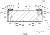
- FIG. 3 is a longitudinal cross section view that is schematically shown along a III-III line of FIG. 2 .
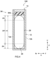
- FIG. 4 is a longitudinal cross section view that is schematically shown along a IV-IV line of FIG. 2 .
- FIG. 5 is a lateral cross section view that is schematically shown along a V-V line of FIG. 2 .
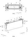
- FIG. 6 is a perspective view that schematically shows an electrode assembly attached to the sealing plate.
- FIG. 7 is a perspective view that schematically shows the electrode assembly to which a positive electrode second electrical collector part and a negative electrode second electrical collector part are attached.
- FIG. 3 is a longitudinal cross section view that is schematically shown along a III-III line of FIG. 2 .
- FIG. 4 is a longitudinal cross section view that is schematically shown along a IV-IV line of FIG. 2 .
- FIG. 5 is a lateral cross section view that is schematically shown along a V-V line of FIG
- FIG. 8 is a schematic view that shows a configuration of the electrode assembly 20.
- reference signs L, R, F, Rr, U, and D in drawings respectively represent left, right, front, rear, up, and down
- reference signs X, Y, and Z in drawings respectively represent a short side direction, a long side direction orthogonal to the short side direction, and a vertical direction of the secondary battery 100.
- the secondary battery 100 manufactured by the herein disclosed manufacturing method includes a battery case 10, an electrode assembly 20, a positive electrode terminal 30, a negative electrode terminal 40, a positive electrode collecting member 50, and a negative electrode collecting member 60. As the illustration is omitted, the secondary battery 100 here further includes an electrolyte solution.
- the secondary battery 100 here is a lithium ion secondary battery.
- the battery case 10 is a housing configured to accommodate the electrode assembly 20.
- the battery case 10 here has an outer appearance that is formed in a flat and bottomed rectangular parallelopiped shape (square shape).
- a material of the battery case 10 may be the same as a material conventionally used, and is not particularly restricted. It is preferable that the battery case 10 is made of metal, or it is further preferable that, for example, the battery case is made of aluminum, aluminum alloy, iron, iron alloy, or the like.
- the battery case 10 includes an outer package 12 including an opening 12h, and includes a sealing plate (lid body) 14 configured to cover the opening 12h.
- the outer package 12 includes a bottom wall 12a, a pair of longer side walls 12b that extend from the bottom wall 12a and are opposed mutually, and a pair of shorter side walls 12c that extend from the bottom wall 12a and are opposed mutually.
- the bottom wall 12a is formed in an approximately rectangular shape.
- the bottom wall 12a is opposed to the opening 12h.
- An area of the shorter side wall 12c is smaller than an area of the longer side wall 12b.
- the sealing plate 14 is attached to the outer package 12 to cover the opening 12h of the outer package 12.
- the sealing plate 14 is opposed to the bottom wall 12a of the outer package 12.
- the sealing plate 14 is approximately rectangular in a plane view.
- the sealing plate 14 is provided with a liquid injection hole 15, a gas exhaust valve 17, and two terminals taking out holes 18, 19.
- the terminal taking out holes 18, 19 are respectively provided at both end parts of the sealing plate 14 in a long side direction Y.
- the terminal taking out holes 18, 19 penetrate the sealing plate 14 in a vertical direction Z.
- the terminal taking out holes 18, 19 respectively have inner diameters capable of inserting the positive electrode terminal 30 and the negative electrode terminal 40 before being attached to the sealing plate 14.
- the liquid injection hole 15 is for performing liquid injection of the electrolyte solution at a liquid injection step described later.
- the liquid injection hole 15 is sealed by a sealing member 16.
- the gas exhaust valve 17 is configured to be broken when a pressure inside the battery case 10 becomes equal to or more than a predetermined value, to exhaust the gas inside the battery case 10 to the outside.
- the secondary battery 100 includes the electrolyte solution.
- the electrolyte solution may be the same as conventional one, and is not particularly restricted.
- the electrolyte solution is, for example, a nonaqueous electrolyte solution that contains a nonaqueous solvent and a supporting salt.
- the nonaqueous solvent contains, for example, carbonates, such as ethylene carbonate, dimethyl carbonate, and ethyl methyl carbonate. It is preferable that the nonaqueous type solvent contains a chain-like carbonate and a ring-shaped carbonate.
- the supporting salt is, for example, a fluorine-containing lithium salt, such as LiPF 6 .
- the electrolyte solution may contain an additive agent, as needed.
- the positive electrode terminal 30 and the negative electrode terminal 40 both are fixed to the sealing plate 14.
- the positive electrode terminal 30 is arranged at one side (left side in FIG. 2 and FIG. 3 ) in a long side direction Y of the sealing plate 14.
- the positive electrode terminal 30 as described above is electrically connected at an outside of the battery case 10 to a positive electrode outside conductive member 32 formed in a plate shape. It is preferable that the positive electrode terminal 30 is made of metal, or it is further preferable that the positive electrode terminal is made of, for example, aluminum or aluminum alloy.
- the negative electrode terminal 40 is arranged at the other side (right side in FIG. 2 and FIG. 3 ) in the long side direction Y of the sealing plate 14.
- the negative electrode terminal 40 as described above is electrically connected at the outside of the battery case 10 to a negative electrode outside conductive member 42 formed in a plate shape. It is preferable that the negative electrode terminal 40 is made of metal, or it is further preferable that the negative electrode terminal is made of, for example, copper or copper alloy.
- the negative electrode terminal 40 may be configured by joining two conductive members to be integrated. For example, a later described portion connected to the negative electrode collecting member 60 may be made of copper or copper alloy, and a portion exposed on the outside surface of the sealing plate 14 may be made of aluminum or aluminum alloy.
- a metal (aluminum, aluminum alloy, copper, copper alloy, or the like) having an outstanding electrically conductive property can be suitably used even for the electrode collecting member (positive electrode collecting member 50 and negative electrode collecting member 60).
- the positive electrode outside conductive member 32 and the negative electrode outside conductive member 42 are members on which a bus bar is disposed, when plural secondary batteries 100 are electrically connected to each other.
- the positive electrode outside conductive member 32 and the negative electrode outside conductive member 42 are made of metal, or it is further preferable that the positive electrode terminal is made of, for example, aluminum or aluminum alloy.
- the positive electrode outside conductive member 32 and the negative electrode outside conductive member 42 are not essential, and may be omitted in another embodiment.
- the electrode assembly 20 is accommodated in the battery case 10.
- a positive electrode tab group 23 and a negative electrode tab group 25 are provided on the electrode assembly 20.
- the above-described positive electrode terminal 30 is connected via the positive electrode collecting member 50 to a positive electrode tab group 23 of the electrode assembly 20.
- the positive electrode collecting member 50 is accommodated inside the battery case 10. As shown in FIG. 3 and FIG.
- this positive electrode collecting member 50 includes a positive electrode first electrical collector part 51 that is a plate-shaped conductive member extending in the long side direction Y along an inside surface of the sealing plate 14, and includes a positive electrode second electrical collector part 52 that is a plate-shaped conductive member extending along the vertical direction Z. Then, a lower end part 30c of the positive electrode terminal 30 is inserted into the battery case 10 through a terminal taking out hole 18 of the sealing plate 14 to be connected to the positive electrode first electrical collector part 51 (see FIG. 3 ). Additionally, as shown in FIG. 5 to FIG. 7 , the positive electrode second electrical collector part 52 is connected to the positive electrode tab group 23 of the electrode assembly 20.
- the positive electrode tab group 23 of the electrode assembly 20 is folded and bent to make the positive electrode second electrical collector part 52 and one side surface 20e of the electrode assembly 20 be opposed to each other. By doing this, a top end part of the positive electrode second electrical collector part 52 and the positive electrode first electrical collector part 51 are electrically connected.
- the negative electrode terminal 40 is connected via the negative electrode collecting member 60 to the negative electrode tab group 25 of the electrode assembly 20.
- the connecting structure at the negative electrode side as described above is approximately the same as the connecting structure at the above-described positive electrode side.
- the negative electrode collecting member 60 includes a negative electrode first electrical collector part 61 that is a plate-shaped conductive member extending in the long side direction Y along the inside surface of the sealing plate 14 and includes a negative electrode second electrical collector part 62 that is a plate-shaped conductive member extending along the vertical direction Z (see FIG. 3 and FIG. 6 ).
- a lower end part 40c of the negative electrode terminal 40 is inserted into the battery case 10 through the terminal taking out hole 19 to be connected to the negative electrode first electrical collector part 61 (see FIG. 3 ).
- the negative electrode second electrical collector part 62 is connected to a negative electrode tab group 25 of the electrode assembly 20.
- the negative electrode tab group 25 is folded and bent to make the negative electrode second electrical collector part 62 and the other side surface 20g of the electrode assembly 20 be opposed to each other. By doing this, a top end part of the negative electrode second electrical collector part 62 and the negative electrode first electrical collector part 61 are electrically connected.
- an outside insulating member 92 is disposed between the positive electrode outside conductive member 32 (negative electrode outside conductive member 42) and an outside surface of the sealing plate 14 (see FIG. 2 and FIG. 3 ). By doing this, it is possible to inhibit the positive electrode outside conductive member 32 or the negative electrode outside conductive member 42 from conducting with the sealing plate 14.
- a gasket 90 is attached to each of the terminals taking out holes 18, 19 of the sealing plate 14 (see FIG. 3 ). By doing this, it is possible to inhibit the positive electrode terminal 30 (or negative electrode terminal 40) inserted into the terminal taking out hole 18, 19 from conducting with the sealing plate 14.
- an inside insulating member 94 is arranged between the positive electrode first electrical collector part 51 (or negative electrode first electrical collector part 61) and an inside surface of the sealing plate 14.
- This inside insulating member 94 includes a plate-shaped base part 94a disposed between the positive electrode first electrical collector part 51 (or negative electrode first electrical collector part 61) and the inside surface of the sealing plate 14. By doing this, it is possible to inhibit the positive electrode first electrical collector part 51 or the negative electrode first electrical collector part 61 from conducting with the sealing plate 14.
- the inside insulating member 94 includes a protruding part 94b that protrudes from the inside surface of the sealing plate 14 to the electrode assembly 20 (see FIG. 3 and FIG. 4 ).
- the electrode assembly 20 is accommodated inside the battery case 10 in a state of being covered by an electrode assembly holder 29 consisting of a resin sheet having an insulating property (see FIG. 4 ). By doing this, it is possible to inhibit the electrode assembly 20 and the outer package 12 from directly coming into contact to each other.
- a material of each insulating member described above is not particularly restricted, if having a predetermined insulating property.
- a synthetic resin material such as polyolefin type resin (example: polypropylene (PP), polyethylene (PE)), fluorine type resin (example: perfluoro alkoxy alkane (PFA), polytetrafluoroethylene (PTFE)), or the like.
- FIG. 8 is a schematic view that shows a configuration of the electrode assembly 20.
- the electrode assembly 20 includes a positive electrode plate 22 and a negative electrode plate 24.
- the electrode assembly 20 here is a flat-shaped wound electrode assembly in which the positive electrode plate 22 formed in a strip-like shape and the negative electrode plate 24 formed in a strip-like shape are laminated via a separator 26 formed in a strip-like shape to be wound about a wound axis WL treated as the center.
- the electrode assembly 20 is disposed inside the outer package 12 in a direction in which the wound axis WL of each wound electrode assembly extends along the bottom wall 12a (in other words, in a direction in which the wound axis WL is parallel to the long side direction Y).
- the electrode assembly 20 is arranged inside the outer package 12, with the wound axis WL being in parallel to the bottom wall 12a and being in a direction orthogonal to the shorter side wall 12c.
- An end surface of the electrode assembly 20 (in other words, laminate surface on which the positive electrode plate 22 and the negative electrode plate 24 are laminated, or an end surface in the long side direction Y of FIG. 8 ) is opposed to the shorter side wall 12c.
- the electrode assembly 20 includes a pair of bent parts 20r whose outer surfaces are bent, and includes a flat part 20f which couples the pair of bent parts 20r and whose surface is flat.
- the electrode assembly 20 may be a laminate electrode body in which plural square shaped (typically, rectangular) positive electrodes and plural square shaped (typically, rectangular) negative electrodes are stacked in a state of being insulated.
- a height of the electrode assembly 20 (length in the vertical direction Z) H1 is preferably equal to or less than 12 cm, or further preferably equal to or less than 10 cm.
- the height of the electrode assembly 20 means a length in a direction perpendicular to a thickness direction (short side direction X) of the electrode assembly 20.
- the positive electrode plate 22 is a member formed in a long strip-like shape.
- the positive electrode plate 22 includes a positive electrode substrate 22c, and includes a positive electrode active material layer 22a and positive electrode protective layer 22p, fixed at least one surface of the positive electrode substrate 22c.
- the positive electrode protective layer 22p is not essential, and may be omitted in another embodiment.
- the positive electrode substrate 22c is formed in a strip-like shape.
- the positive electrode substrate 22c consists, for example, of an electrically conductive metal, such as aluminum, aluminum alloy, nickel, and stainless steel.
- the positive electrode substrate 22c here is a metal foil, specifically, an aluminum foil.
- an average thickness of the positive electrode substrate 22c is not particularly restricted.
- the average thickness is preferably 2 ⁇ m to 30 ⁇ m, further preferably 2 ⁇ m to 20 ⁇ m, or furthermore preferably 5 ⁇ m to 15 ⁇ m.
- plural positive electrode tabs 22t are provided.
- the plural positive electrode tabs 22t protrude to one side (left side in FIG. 8 ) in the long side direction Y.
- the plural positive electrode tabs 22t protrude in the long side direction Y more than the separator 26.
- the plural positive electrode tabs 22t are provided at intervals (intermittently) along a longitudinal direction of the positive electrode plate 22.
- the positive electrode tab 22t may be provided at the other end part (right end part in FIG. 8 ) in the long side direction Y, or may be provided at both end parts in the long side direction Y.
- the positive electrode tab 22t is a part of the positive electrode substrate 22c and consists of a metal foil (aluminum foil). At least a part of the positive electrode tab 22t fails to include the positive electrode active material layer 22a and the positive electrode protective layer 22p, but includes the positive electrode substrate 22c being exposed.
- the positive electrode active material layer 22a is provided in a strip-like shape along a longitudinal direction of the positive electrode substrate 22c formed in a strip-like shape.
- the positive electrode active material layer 22a contains a positive electrode active material that can reversibly store and release a charge carrier (for example, lithium transition metal composite oxide, such as lithium-nickel-cobalt-manganese composite oxide).
- a charge carrier for example, lithium transition metal composite oxide, such as lithium-nickel-cobalt-manganese composite oxide.
- the positive electrode active material may occupy approximately 80 mass% or more, typically 90 mass% or more, or, for example, 95 mass% or more.
- the positive electrode active material layer 22a may contain an arbitrary component other than the positive electrode active material, for example, an electrical conducting material, a binder, various additive components, or the like.
- an electrical conducting material for example, it is possible to use a carbon material, such as acetylene black (AB).
- AB acetylene black
- the binder for example, it is possible to use polyvinylidene fluoride (PVdF), or the like.
- the positive electrode protective layer 22p is provided at a boundary portion between the positive electrode substrate 22c and the positive electrode active material layer 22a in the long side direction Y.
- the positive electrode protective layer 22p here is provided at one end part (left end part in FIG. 8 ) of the positive electrode substrate 22c in the long side direction Y.
- the positive electrode protective layer 22p may be provided at both end parts in the long side direction Y.
- the positive electrode protective layer 22p is provided in a strip-like shape along the positive electrode active material layer 22a.
- the positive electrode protective layer 22p contains an inorganic filler (for example, alumina).
- the inorganic filler may occupy approximately 50 mass% or more, typically 70 mass% or more, or, for example, 80 mass% or more.
- the positive electrode protective layer 22p may contain an arbitrary component other than the inorganic filler, for example, an electrical conducting material, a binder, various additive components, or the like.
- the electrical conducting material and the binder may be the same as ones illustrated as components capable of being contained in the positive electrode active material layer 22a.
- the negative electrode plate 24 is a member formed in a long strip-like shape.
- the negative electrode plate 24 includes a negative electrode substrate 24c, and includes a negative electrode active material layer 24a fixed on at least one surface of the negative electrode substrate 24c.
- the negative electrode substrate 24c is formed in a strip-like shape.
- the negative electrode substrate 24c consists of, for example, an electrically conductive metal, such as copper, copper alloy, nickel, and stainless steel.
- the negative electrode substrate 24c here is a metal foil, specifically, a copper foil.
- plural negative electrode tabs 24t are provided.
- the plural negative electrode tabs 24t protrude to the long side direction Y, more than the separator 26.
- the plural negative electrode tabs 24t are provided at intervals (intermittently) along a longitudinal direction of the negative electrode plate 24.
- the negative electrode tab 24t protrudes to one side (right side in FIG. 8 ) in the long side direction Y.
- the negative electrode tab 24t may be provided at the other end part (left end part in FIG. 8 ) in the long side direction Y, or may be provided at both end parts in the long side direction Y.
- the negative electrode tab 24t is a part of the negative electrode substrate 24c and consists of a metal foil (copper foil). At a part of the negative electrode tabs 24t, a negative electrode active material layer 24a is disposed. At least a part of the negative electrode tab 24t fails to include the negative electrode active material layer 24a and includes the negative electrode substrate 24c being exposed.
- the negative electrode active material layer 24a is provided in a strip-like shape along the longitudinal direction of the strip-like shaped negative electrode substrate 24c.
- the negative electrode active material layer 24a contains a negative electrode active material (for example, carbon material, such as graphite) that can reversibly store and release a charge carrier.
- a total solid content of the negative electrode active material layer 24a is treated as 100 mass%, the negative electrode active material may occupy approximately 80 mass% or more, typically 90 mass% or more, or, for example, 95 mass% or more.
- the negative electrode active material layer 24a may contain an arbitrary component other than the negative electrode active material, for example, a binder, a dispersing agent, various additive components, or the like.
- the binder for example, rubbers, such as styrene butadiene rubber (SBR) can be used.
- SBR styrene butadiene rubber
- the dispersing agent for example, celluloses, such as carboxymethyl cellulose (CMC) can
- a width W1 (see FIG. 8 ) of a main body part of the negative electrode plate 24 excluding the negative electrode tabs 24t is equal to or more than 20 cm.
- the width W1 of the main body part of the negative electrode plate 24 is, for example, preferably 20 cm to 45 cm, or further preferably 25 cm to 35 cm.
- the width of the main body part of the negative electrode plate means a length in the short direction of the strip-shaped negative electrode plate.
- the electrode assembly 20 includes two separators 26.
- Each of the separators 26 is a member that insulates the positive electrode active material layer 22a of the positive electrode plate 22 and the negative electrode active material layer 24a of the negative electrode plate 24.
- the separator 26 configures an outer surface of the electrode assembly 20.
- FIG. 9 is a view that schematically shows a boundary between the positive electrode plate 22 and negative electrode plate 24 of the electrode assembly 20 and the separator 26.
- the separator 26 in the present embodiment includes a base material layer 26a formed in a strip-like shape, and includes an adhesion layer 26b arranged on a surface (both surfaces) of the base material layer 26a.
- one adhesion layer 26b of the separator 26 configured as described above and the positive electrode plate 22 are adhered, and the other adhesion layer 26b and the negative electrode plate 24 are adhered.
- a thickness t1 (see FIG. 9 ) of the separator 26 is, for example, preferably 5 ⁇ m to 40 ⁇ m, further preferably 8 ⁇ m to 30 ⁇ m, or furthermore preferably 12 ⁇ m to 20 ⁇ m.
- thickness t1 of the separator 26 in the present specification means a total thickness with respect to the base material layer 26a and the adhesion layer 26b, and means a thickness before a press molding process if not particularly mentioned.
- the base material layer 26a is a porous sheet made of resin consisting of polyolefin resin, such as polyethylene (PE) and polypropylene (PP).
- a thickness t2 (see FIG. 9 ) of the base material layer 26a is, for example, preferably 4 ⁇ m to 35 ⁇ m, further preferably 8 ⁇ m to 25 ⁇ m, or furthermore preferably 10 ⁇ m to 20 ⁇ m.
- a void rate of the base material layer 26a is, for example, preferably 20% to 70%, or further preferably 30% to 60%.
- thickness of the base material layer 26a and “void rate of the base material layer 26a” in the present specification respectively represent a thickness and a void rate before the press molding process, if not particularly mentioned.
- the adhesion layers 26b in the present embodiment are layers arranged on both surfaces of the base material layer 26a.
- the adhesion layer 26b contains a binder and an inorganic particle.
- the adhesion layers 26b may be configured similarly or differently at a side opposed to the positive electrode plate 22 and at a side opposed to the negative electrode plate 24.
- the separator 26 includes a porous base material layer 26a made of a polyolefin resin and the both surfaces are the adhesion layers 26b.
- the adhesion layer 26b contains polyvinylidene fluoride (PVdF). Another layer may be arranged between the adhesion layer 26b and the base material layer 26a.
- PVdF polyvinylidene fluoride
- the binder contained in the adhesion layer 26b it is possible without restriction to use a conventionally known resin material having a constant adhesive property.
- a thermoplastic resin for example, a fluorine type resin, such as polyvinylidene fluoride (PVdF) and polytetrafluoroethylene (PTFE); a polyester resin, such as polyethylene terephthalate; a polyamide type resin; a polyimide type resin; an acrylic resin; or the like.
- the adhesion layer 26b may contain two or more types of these binder resins.
- PVdF is preferably used because of suitably inducing an adhesive property with respect to the electrode plate.
- a content amount of the binder contained in the adhesion layer 26b is preferably equal to or more than 10 mass%, further preferably equal to or more than 15 mass%, and furthermore preferably equal to or more than 20 mass%.
- an upper limit of the content amount of the binder contained in the adhesion layer 26b may be equal to or less than 50 mass%, equal to or less than 45 mass%, or equal to or less than 40 mass%.
- the binder contained in the adhesion layer 26b be within the above-described range, it is possible to induce a suitable adhesive property.
- the positive electrode plate 22 and negative electrode plate 24, and the adhesion layer 26b are adhered, for example, by press.
- the press can be performed, for example, at a room temperature, or in a heated state.
- the inorganic particles include ceramic particles containing ceramics such as alumina, boehmite, aluminum hydroxide, titania, magnesium carbonate, magnesia, zirconia, zinc oxide, iron oxide, ceria, and yttria as main components. It is preferable that a content amount of the inorganic particle of the adhesion layer 26b is adjusted to induce a predetermined adhesive property with respect to the positive electrode plate 22 (or negative electrode plate 24).
- the adhesion layer 26b includes a three-dimensional net structure having plural voids.
- the inorganic particles are dispersed.
- the adhesion layer 26b may be configured such that a plurality of fiber-shaped PVdFs are randomly laminated so as to have multiple voids to form a three-dimensional network structure, and inorganic particles, such as alumina and boehmite are dispersed inside the three-dimensional network structure.
- a thickness t3 of the adhesion layer 26b is, for example, preferably equal to or more than 0.5 ⁇ m, further preferably equal to or more than 1.0 ⁇ m, or furthermore preferably equal to or more than 1.5 ⁇ m.
- the thickness t3 of the adhesion layer 26b which is not particularly restricted, for example, preferably equal to or less than 10 ⁇ m, further preferably equal to or less than 8 ⁇ m, or furthermore preferably equal to or less than 6 ⁇ m. By doing this, it is possible to induce a suitable adhesive property.
- a basis weight amount of the adhesion layer 26b is preferably equal to or more than 1 g/m 2 , further preferably equal to or more than 2 g/m 2 , or furthermore preferably equal to or more than 2.5 g/m 2 .
- the basis weight amount of the adhesion layer 26b is, for example, preferably equal to or less than 8 g/m 2 , further preferably equal to or less than 6 g/m 2 , or furthermore preferably equal to or less than 5.5 g/m 2 .
- a void rate of the adhesion layer 26b is preferably equal to or more than 10%, further preferably equal to or more than 30%, or furthermore preferably equal to or more than 50%.
- a void rate of the adhesion layer 26b is preferably equal to or less than 90%, or further preferably equal to or less than 80%.
- thickness of the adhesion layer 26b and void rate of the adhesion layer 26b in the present specification respectively represent a thickness and void rate before the press molding process, if not particularly mentioned.
- the herein disclosed manufacturing method of the secondary battery is characterized by including a peeling step S20 and thus the other manufacturing processes are not particularly restricted.
- An arranging step S10 is a step for arranging the electrode assembly 20 as described above inside the battery case 10.
- the electrode assembly 20, the battery case 10 (outer package 12 and sealing plate 14), the positive electrode terminal 30, the negative electrode terminal 40, the positive electrode collecting member 50 (positive electrode first electrical collector part 51 and positive electrode second electrical collector part 52), and the negative electrode collecting member 60 (negative electrode first electrical collector part 61 and negative electrode second electrical collector part 62), as described above, are prepared.
- the electrode assembly 20 is inserted into the battery case 10.
- the electrode assembly 20 may be a laminate electrode assembly as described above.
- the positive electrode plate 22 and the negative electrode plate 24 are laminated via 2 sheets of separators 26 and then the resultant is wound to prepare the electrode assembly 20.
- the separator 26 formed in a strip-like shape, the negative electrode plate 24 formed in a strip-like shape, the separator 26 formed in a strip-like shape, and the positive electrode plate 22 formed in a strip-like shape are laminated in this order to manufacture the laminate body (see FIG. 8 ).
- a laminate position of each sheet member in the long side direction Y is adjusted, to make only the positive electrode tabs 22t of the positive electrode plate 22 protrude from one side edge (left side in FIG.
- the manufactured laminate body is wound to manufacture a cylindrical body. It is preferable that a wound number at that time is suitably adjusted in consideration of the intended performance or manufacture efficiency for the target electrode assembly 20.
- the wound number of the electrode assembly 20 on the positive electrode plate 22 is preferably 10 to 60, or further preferably 30 to 40.
- press molding is performed on the above manufactured cylindrical body, to prepare the flat-shaped electrode assembly 20.
- the press molding process may be performed at a room temperature or may be performed at a heated state (for example, about 40°C to 80°C).
- a heated state for example, about 40°C to 80°C.
- the separator 26 includes an adhesion layer 26b having a predetermined adhesive property, and thus by performing the press molding process on the electrode assembly 20 having the above-described adhesion layer 26b, the adhesion layer 26b of the separator 26 and the positive electrode plate 22 are suitably adhered and the adhesion layer 26b and the negative electrode plate 24 are suitably adhered, so that the spring back is suppressed. By doing this, it is possible at the arrangement processing to smoothly arrange the electrode assembly 20 at a desired position.
- the prepared electrode assembly 20 described above is accommodated into the battery case 10.
- a combined member is prepared in which the positive electrode collecting member 50, the negative electrode collecting member 60, and the sealing plate 14 are attached to the electrode assembly 20.
- the positive electrode second electrical collector part 52 is joined to the positive electrode tab group 23 of the electrode assembly 20, and the negative electrode second electrical collector part 62 is joined to the negative electrode tab group 25.
- the sealing plate 14 is arranged an upward of the electrode assembly 20, and then, as shown in FIG. 5 , the positive electrode tab group 23 of the electrode assembly 20 is folded and bent to make the positive electrode second electrical collector part 52 and one side surface 20e of the electrode assembly 20 be opposed to each other.
- each wound electrode assembly 20 is attached to the sealing plate 14 via the positive electrode collecting member 50 and the negative electrode collecting member 60.
- the electrode assembly 20 being attached to the sealing plate 14 is accommodated into the electrode assembly holder 29 (see FIG. 4 ).
- the electrode assembly 20 being covered by the electrode assembly holder 29 is inserted into the outer package 12.
- the wound axis WL is preferably inserted to be disposed inside the outer package 12in a direction along the bottom wall 12a (in other words, a direction in which the wound axis WL is parallel to the long side direction Y). By doing this, it is possible to efficiently heat the electrode assembly 20 at the later-described heating process.
- the sealing plate 14 is joined to an edge part of the opening 12h of the outer package 12 to seal the opening 12h. By doing this, it is possible to prepare a battery assembly in which the electrode assembly 20 is arranged inside the battery case 10.
- the electrode assembly holder 29 for example, by folding and bending a resin sheet, having an insulating property, and being made of a resin material, such as polyethylene (PE), to make the resin sheet be formed in a bag shape or a box shape.
- a resin material such as polyethylene (PE)
- the outer package 12 and the sealing plate 14 are sealed, for example, by welding and joining. Welding and joining the outer package 12 and the sealing plate 14 can be implemented, for example, by laser welding, or the like.
- a peeling step S20 is a step for peeling off at least one, among the positive electrode plate 22 and negative electrode plate 24 of the electrode assembly 20 accommodated in the battery assembly prepared at the arranging step S10, and the separator 26.
- the later described heating process and first decompressing process are performed, so as to peel off the positive electrode plate 22 and negative electrode plate 24, and the separator 26, and thus to make the electrode assembly 20 be in a state of including a peeled area.
- the peeled area it is preferable in the peeled area that a gap is generated between the positive electrode plate 22 or negative electrode plate 24 and the separator 26.
- the presence or absence of the peeled area can be determined from an X-ray CT image which is a cross section perpendicular to the wound axis at a central part in the wound axis direction of the electrode assembly.
- the heating process is a process to soften the adhesion layer 26b of the separator 26 and facilitate peeling of the separator 26 from the positive electrode plate 22 and the negative electrode plate 24. It is preferable that a temperature of the heating process as described above is held, for example, to make a temperature of the electrode assembly 20 be equal to or more than 80°C, although the temperature is different based on the kind of binder used in the adhesion layer 26b and thus it is difficult to define the temperature strictly. Regarding the heating process, the temperature of the electrode assembly 20 is held further preferably to be equal to or more than 90°C, or the temperature of the electrode assembly 20 is held furthermore preferably to be equal to or more than 100°C.
- the temperature of the electrode assembly 20 is held, for example, preferably to be equal to or less than 130°C, or further preferably to be equal to or less than 120°C.
- a temperature rising speed which is not particularly restricted, may be set, for example, about 4°C/min to 8°C/min.
- a time for the heating process may be, for example, about 1 hour to 6 hours, or can be set about 1.5 hours to 4 hours, although being different based on a size or the like of the secondary battery 100.
- the heating process is held for 1 hour or more in a state where the temperature of the electrode assembly 20 is held to be equal to or more than 80°C, or further preferable that the heating process is held for 1 hour or more in a state where the temperature of the electrode assembly 20 is held to be 90°C or more.
- the means for heating is not particularly limited as it satisfies the above condition.
- the means for heating may be implemented, for example, by placing the battery assembly on a based-shaped heating plate in which the electric heater is stored.
- the battery assembly may be disposed silently in a thermostatic chamber, or the like, which is set to hold a predetermined temperature, to perform heating.
- the first decompressing process is a process for decompressing the inside of the battery assembly after the heating process to be lower than the atmospheric pressure (in other words, the pressure of air outside the battery assembly), and separating the positive electrode plate 22 and negative electrode plate 24 from the separator 26.
- the atmospheric pressure in other words, the pressure of air outside the battery assembly
- a decompression speed for the decompressing process described above is set to be faster than a conventional one, it is possible to suitably peel off the positive electrode plate 22 and negative electrode plate 24, and the separator 26.
- a reason why the effect as described above can be obtained is estimated as described below.
- the inside of the battery assembly in other words, inside of the battery case
- the inside of the electrode assembly accommodated in the battery case is also decompressed.
- the pressure inside the electrode assembly cannot follow the decompression speed of the battery case, a differential pressure is caused between the inside of the battery case and the inside of the electrode assembly, and thus the electrode assembly expands. It is estimated that, because of the expansion effect as described above, the positive electrode plate and negative electrode plate of the electrode assembly and the separators are peeled off.
- the decompression speed at the first decompressing process is set to be a relatively higher speed, in order to peel off at least one among the positive electrode plate 22 and negative electrode plate 24 of the electrode assembly 20, and the separator 26. It is preferable that the decompression speed is, at least, equal to or more than 30 kPa/min. For example, the decompression speed is further preferably equal to or more than 40 kPa/min, or furthermore preferably equal to or more than 50 kPa/min.
- the decompression speed is preferably equal to or less than 500 kPa/min, further preferably equal to or less than 250 kPa/min, or furthermore preferably equal to or less than 100 kPa/min.
- the pressure inside the battery assembly is, based on the absolute pressure, preferably decompressed to be equal to or less than 1 kPa, further preferably decompressed to be equal to or less than 100 Pa, or furthermore preferably decompressed to be equal to or less than 50 Pa.
- a time for holding the decompressed state as described above is not particularly restricted, but, for example, may be about 1 hour to 8 hours, or can be about 1 hour to 5 hours.
- a timing for starting the first decompressing process is not particularly restricted, but from a perspective of suitably peeling off the electrode assembly 20, it is preferable that the first decompressing process is started after the battery assembly is sufficiently heated by the heating process.
- decompression is typically started when about 2 hours or more have passed since the heating process is started, or, for example, decompression is preferably started when about 4 hours have passed since the heating process is started.
- the first decompressing process is not particularly limited as long as the first decompressing process is carried out so as to satisfy the above condition.
- the reduced pressure may be reduced by, for example, discharging a gas from the inside of the battery case 10.
- one of the nozzles is attached to the liquid injection hole 15 of the sealing plate 14, and the other one is connected to a vacuum pump. By driving the vacuum pump in this state, the gas inside the battery assembly can be exhausted from the liquid injection hole 15 so as to decompress the inside of the battery assembly.
- a pressurizing step is a step for pressurizing (return-pressurizing) the inside of the battery assembly, decompressed by the first decompressing process, to an extent of the atmospheric pressure.
- This pressurizing step is not a step essential for the herein disclosed technique, and can be suitably omitted.
- a liquid injection step S30 described later may be performed after the above-described first decompressing process.
- the pressure inside the battery assembly is typically pressurized (return-pressured) to an extent of the atmospheric pressure, for example, preferably pressurized to be equal to or more than 5 kPa based on the absolute pressure, or further preferably pressurized to be equal to or more than 10 kPa.
- the upper limit is not particularly restricted, but the pressure inside the battery assembly is preferably pressurized to be equal to or less than 200 kPa based on the absolute pressure, or further preferably pressurized to be equal to or less than 100 kPa.
- the pressurizing (return-pressuring) speed at that time is preferable for the pressurizing (return-pressuring) speed at that time to perform pressurizing relatively slower in order to inhibit the electrode assembly 20 peeled off at the peeling step from being re-adhered.
- the pressurizing speed is preferably set, for example, to be 5000 Pa/min to 80000 Pa/min.
- the pressurizing step it is enough to use a method capable of controlling relative slow pressurizing as described above, and the pressurizing means is not particularly restricted.
- one of the nozzles is attached to the liquid injection hole 15 of the sealing plate 14, and the other is connected to a tank in which the gas is stored.
- the gas introduced here may be similar to a conventional one, and may be, for example, an inert gas, such as nitrogen (N 2 ), a dry air, or the like.
- a liquid injection step S30 is a step for performing liquid injection of the electrolyte solution to the inside of the battery assembly.
- the above-described peeling step S20 implements a state in which the positive electrode plate 22 and negative electrode plate 24, and the separators 26 are peeled off, and it is possible, by performing the liquid injection of the electrolyte solution into the electrode assembly 20 under the state described above, to shorten the liquid injection time for the electrolyte solution and to suppress the electrode assembly 20 be not-uniformly impregnated with the electrolyte solution.
- the second decompressing process is a process for decompressing the inside of the battery assembly, when the above-described pressurizing step is performed, in order to suitably perform the later-described liquid injecting process.
- This second decompressing process is a process not essential for the herein disclosed technique, and can be suitably omitted.
- the later-described liquid injecting process may be performed after the above-described first decompressing process is performed (in other words, while the decompression state is kept).
- the later-described liquid injecting process may be performed without the second decompressing process.
- the pressurizing step it is possible by performing the second decompressing process to perform the liquid injecting process under a state in which the battery assembly is decompressed. By doing this, it is possible to shorten the time required for the liquid injecting process. In addition, it is preferable because the electrolyte solution easily penetrates uniformly into the inside of the electrode assembly 20.
- the second decompressing process is not particularly restricted, if the inside of the battery assembly is decompressed to suitably perform the liquid injecting process.
- the pressure inside the battery assembly may be decompressed to be about 5 kPa to 50 kPa, based on the absolute pressure.
- the time for holding the decompressed state can be set, for example, to be about 100 seconds to 400 seconds.
- the decompression speed can be preferably set, for example, to be 1 kPa/min to 800 kPa/min.
- a means for decompressing at the second decompressing process is not particularly limited, and the decompression may be performed used the same means as the above-described first decompressing process.
- the liquid injecting process is a process for performing liquid injection of the electrolyte solution to the inside of the battery assembly.
- the liquid injecting process may be performed under the atmospheric pressure environment, or may be performed under a reduced-pressure environment. It is preferable that the liquid injecting process is performed under the reduced-pressure environment. By doing this, it is possible to perform the liquid injection of the electrolyte solution, faster.
- the liquid injection of the electrolyte solution is performed to induce a quantity of making the electrolyte solution be distributed over the whole of the electrode assembly 20.
- an inert gas such as nitrogen (N 2 ), dry air, or the like, similarly to conventional one.
- the liquid injection hole 15 of the sealing plate 14 of the battery assembly is sealed. Sealing the liquid injection hole 15 can be performed by assembling a sealing member 16 whose shape is fit for the liquid injection hole 15. By doing this, it is possible to construct the sealed secondary battery 100.
- the initial charging step should be performed in a state where the above-constructed secondary battery 100 is restricted.
- Restricting the secondary battery 100 can be performed by adding a predetermined amount of load to a longer side wall 12b (see FIG. 2 ) of the outer package 12 along a short side direction X.
- a condition for the initial charge may be like conventional one.
- a cycle for charging and discharging with a charge rate whose battery drive voltage range is 0.1 to 2C would be performed about 1 to 5 times.
- the secondary battery 100 can be manufactured.
- the manufacturing method herein disclosed can be used preferably, for example, for a high-capacity type and sealed type battery including an electrode whose area is large so as to take time for electrolyte solution impregnation.
- the secondary battery 100 manufactured by the manufacturing method as described above can be used for various purposes, the secondary battery can be suitably used, for example, as a power source (driving power supply) for a motor mounted on a vehicle, such as passenger car and truck.
- the kind of the vehicle is not particularly restricted, but it is possible to use it, for example, on a plug-in hybrid electric vehicle (PHEV), a hybrid electric vehicle (HEV), a battery electric vehicle (BEV), or the like.
- the secondary battery 100 can be suitably used to construct a battery pack.
- the secondary battery 100 in accordance with the above-described embodiment includes one electrode assembly 20 accommodated in the battery case 10.
- the herein disclosed technique is not restricted to the above-described embodiment.
- the secondary battery may include plural electrode assemblies inside the battery case.
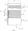
- FIG. 10 is a FIG. 4 corresponding view of a secondary battery 200 in accordance with another embodiment.
- the secondary battery 200 may include a configuration like the above-described secondary battery 100, except for including plural electrode assemblies 20.
- the number of the electrode assemblies accommodated inside one battery case 10 is not particularly restricted if being two or more, and thus the number may be three as shown in a drawing, or not less than four.
- electrode assemblies may be arranged in parallel to make flat parts 20f of respective electrode assemblies be opposed to each other, as shown in FIG. 10 .
- the weight tends to become heavier than a situation of including one electrode assembly.
- the weight is approximately equal to or more than 1 kg, for example, equal to or more than 1.5 kg, or furthermore 2 kg to 3 kg, as shown in FIG. 11 at the arranging step S10, arrangement may be performed to make the longer side wall 12b of the outer package 12 cross the gravity direction (making the outer package 12 be in sideways) and the electrode assemblies 20 may be inserted into the outer package 12.
- the above-described peeling step S20 may be performed to make the peeled area be formed on at least one electrode assembly 20.
- test examples regarding the present disclosure will be described. However, it is not intended that the present disclosure is limited to such test examples.
- a mass ratio of LiNi 1/3 Co 1/3 Mn 1/3 O 2 as a positive electrode active material powder, acetylene black (AB) as an electrical conducting material, and polyvinylidene fluoride (PVdF) as a binder was weighed to be 97 .5:1.5:1.0. These materials were dispersed into N-methyl pyrrolidone (NMP) being as the solvent, so that a paste-like composition for forming a positive electrode active material layer was prepared. This composition was applied on both surfaces of a strip-like shaped positive electrode substrate (aluminum foil) and then dried, to manufacture a strip-like shaped positive electrode plate including a positive electrode active material layer on the coating positive electrode substrate.
- NMP N-methyl pyrrolidone
- a mass ratio of natural graphite (C) as a negative electrode active material, styrene butadiene rubber (SBR) as a binder, and carboxymethyl cellulose (CMC) as a thickening agent was weighed to be 98.3:0.7:1.0. These materials were dispersed into an ion exchange water being as a solvent, so that a paste-like composition for forming a negative electrode active material layer was prepared. The composition was applied on both surfaces of a strip-like shaped negative electrode substrate (copper foil) and then dried, so as to manufacture a strip-like shaped negative electrode plate including a negative electrode active material layer on the negative electrode substrate.
- a separator a member was used in which an adhesion layer including alumina powders and polyvinylidene fluoride (PVdF) were formed on a surface (both surfaces) of a porous base material layer made of polyethylene (PE).
- PVdF polyvinylidene fluoride
- 2 kinds of separators with different thicknesses of adhesion layers were prepared.
- the laminate body in which the above manufactured strip-like shaped positive electrode plate and strip-like shaped negative electrode plate were laminated via the above prepared separator, was manufactured and then this laminate body was wound, so as to manufacture the cylindrical body. Then, a press molding process was performed on the laminate body having been wound, and this laminate body was crushed, so as to manufacture a wound electrode assembly formed in a flat shape.
- the positive electrode terminal and the negative electrode terminal were connected to the manufactured wound electrode assembly, and the resultant was arranged in the battery case including a liquid injection hole. By doing this, the battery assembly for evaluation was manufactured.
- the heating process was performed on the above manufactured battery assembly for evaluation.
- the heating process was performed under a condition whose temperature rising speed was 5°C/min, whose highest temperature was 105°C, and whose highest temperature keeping time was 3.5 hours.
- the first decompressing process was performed, 4 hours later since the heating was started.
- the first decompressing process was performed to decompress the inside of the battery assembly for evaluation at a decompression speed 90 kPa/min to a pressure 10 Pa based on the absolute pressure, whose decompression keeping time was 4 hours.
- the pressurizing step of pressurizing (restoring) to the atmospheric pressure was performed.
- the pressurizing speed was set to be 5000 Pa/min.
- the heating process was performed on the above manufactured battery assembly for evaluation.
- the heating process was performed under the same conditions as in Example 1.
- the first decompressing process was performed, 4 hours later since the heating was started.
- the first decompressing process was performed under the same conditions as in Example 1.
- the pressurizing step of pressurizing (restoring) to the atmospheric pressure was performed.
- the pressurizing speed was set to be 80000 Pa/min.
- Example 3 a thickness of the adhesion layer of the separator was made to be larger than
- the heating process was performed on the above manufactured battery assembly for evaluation.
- the heating process was performed under the same conditions as in Example 1, except that the highest temperature was changed to 90°C.
- the first decompressing process was performed, 4 hours later since the heating was started.
- the pressurizing step of pressurizing (restoring) to the atmospheric pressure was performed.
- the first decompressing process and the pressurizing step were performed under the same conditions as in Example 1.
- the heating process was performed on the above manufactured battery assembly for evaluation.
- the heating process was performed under the same conditions as in Example 1.
- the first decompressing process was performed, 4 hours later since the heating was started.
- the first decompressing process was performed under the same conditions as in Example 1, except that the decompression speed was changed to 10 kPa/min.
- the pressurizing step of pressurizing (restoring) to the atmospheric pressure was performed, under the same conditions as in Example 1.
- the heating process was performed on the above manufactured battery assembly for evaluation.
- the heating process was performed under the same conditions as in Example 1.
- the first decompressing process was performed, 4 hours later since the heating was started.
- the first decompressing process was performed under the same conditions as in Example 1, except that the decompression speed was changed to 20 kPa/min.
- the pressurizing step of pressurizing (restoring) to the atmospheric pressure was performed, under the same conditions as in Example 1.
- the heating process was performed on the above manufactured battery assembly for evaluation.
- the heating process was performed under the same conditions as in Example 1, except that the highest temperature was changed to 60°C.
- the first decompressing process was performed, 4 hours later since the heating was started.
- the pressurizing step of pressurizing (restoring) to the atmospheric pressure was performed.
- the first decompressing process and the pressurizing step were performed under the same conditions as in Example 1.
- each wound electrode assembly central part in the wound axis direction
- a cross section perpendicular to the wound axis was captured by an X-ray CT apparatus (made by Toshiba IT & Control Systems Corporation) and thus X-ray CT images for each example and each comparative example were obtained. Then, on the X-ray CT image, the presence or absence of peeled area at the flat part 20f of the electrode assembly 20 was confirmed.
- a distance between a center in a thickness direction of one positive electrode plate 22 among 2 layers of positive electrode plates 22 arranged adjacent in the laminate direction of the positive electrode plates 22 and a center in the thickness direction of the other positive electrode plate 22 was represented by a distance D ( ⁇ m).
- a total thickness of respective members disposed between the above-described two centers (total thickness of a half of the thickness of one positive electrode plate 22, a thickness of one separator 26, a thickness of negative electrode plate 24, a thickness of the other separator 26, and a half of the thickness of the other positive electrode plate 22) was represented by a thickness T ( ⁇ m).
- a portion whose distance D ( ⁇ m) was 30 ⁇ m or larger than the thickness T( ⁇ m) was determined to include the peeled area. Results are shown in Table 1.
- the second decompressing process was performed to decompress the inside pressure of the battery assembly for evaluation to 5 kPa based on the absolute pressure, and then, the liquid injecting process was performed to implement the liquid injection of the above-described electrolyte solution.
- Ratio of liquid injection time for each example or each comparative example, when the liquid injection time for Comparative Example 1 is treated as 1, is shown in Table 1.
- one positive electrode active material layer 22a, one separator 26, the negative electrode plate 24, the other separator 26, and the other positive electrode active material layer 22a which are disposed between respective positive electrode substrates 22c included by 2 layers of positive electrode plates 22 adjacent in the laminate direction, are treated as one unit.
- a unit in which the peeled area is formed on at least one among a boundary surface between the positive electrode plate 22 and the separator 26 arranged in this unit and a boundary surface between the negative electrode plate 24 and the separator 26 arranged in this unit it is preferable that 3 or more units are formed at the flat part 20f of the electrode assembly 20, or it is preferable that 5 or more units are formed at the flat part of the electrode assembly.
- a total laminate number of the positive electrode plates 22 is N, it is preferable that 0.1 N or more of the peeled areas are formed at the flat part 20f of one electrode assembly 20, or it is further preferable that 0.2 N or more of the peeled areas are formed at the flat part of one electrode assembly.
- a width of the peeled area is preferably equal to or more than 10 mm, further preferably equal to or more than 20 mm, or furthermore preferably equal to or more than 30 mm.
- W3/W2 is preferably equal to or more than 0.1, further preferably equal to or more than 0.2, or furthermore preferably equal to or more than 0.3.
Landscapes
- Chemical & Material Sciences (AREA)
- Chemical Kinetics & Catalysis (AREA)
- Electrochemistry (AREA)
- General Chemical & Material Sciences (AREA)
- Engineering & Computer Science (AREA)
- Manufacturing & Machinery (AREA)
- Secondary Cells (AREA)
- Materials Engineering (AREA)
- Battery Electrode And Active Subsutance (AREA)
- Electric Double-Layer Capacitors Or The Like (AREA)
- Sealing Battery Cases Or Jackets (AREA)
- Cell Separators (AREA)
Abstract
Description
- The present disclosure relates to a manufacturing method of a secondary battery.
- A secondary battery, such as a lithium ion secondary battery, generally includes an electrode assembly provided with a positive electrode and a negative electrode, an outer package having an opening and configured to accommodate the electrode assembly and an electrolyte solution, and a sealing plate configured to seal the opening of the outer package, and is configured with the outer package and the sealing plate being sealed.
Japanese Patent Application Publication No. 2018-185899 - Anyway, from a perspective of implementing a higher capacity of the battery, it recently tends to increase a size of an electrode assembly. According to a result of investigation by the present inventors, the present inventors have found that it takes a longer time to inject an electrolyte solution into the electrode assembly which is larger than the conventional electrode assembly, and it is difficult to uniformly impregnate the entire electrode assembly with the electrolyte solution.
- The present disclosure has been made to solve the above-described problem and to provide a method for efficiently manufacturing a more reliable secondary battery.
- A method of manufacturing battery includes an electrode assembly having a positive electrode, a negative electrode, and a separator arranged between the positive electrode and the negative electrode, and a battery case configured to accommodate the electrode assembly. The separator is provided with adhesion layers formed on both surfaces of the separator. The manufacturing method includes: an arranging step for arranging the electrode assembly, in which the positive electrode and the separator are adhered by the adhesion layer and in which the negative electrode and the separator are adhered by the adhesion layer, inside the battery case; a peeling step for peeling off at least one, among the positive electrode and the negative electrode, and the separator in the electrode assembly; and a liquid injection step for performing a liquid injection of an electrolyte solution into the battery case after the peeling step.
- As described above, by the peeling step, at least one, among the positive electrode and negative electrode, and the separator are peeled off. By doing this, it is possible to perform the liquid injection of the electrolyte solution during a shorter time at the liquid injection step. In addition, it is possible to suppress impregnation with the electrolyte solution to the electrode assembly from being not uniform. By suppressing the impregnation with the electrolyte solution to the electrode assembly from being not uniform, reduction in the battery characteristic caused by coating film formation failure, lithium precipitation, or the like, can be suppressed. Therefore, according to the configuration as described above, it is possible to implement a method for further efficiently manufacturing the more reliable secondary battery.
- In one aspect of the herein disclosed manufacturing method, the peeling step includes a heating process for heating a temperature of the electrode assembly to be equal to or more than 80°C, and a first decompressing process for decompressing an inside of the battery case in a state where the temperature of the electrode assembly becomes equal to or more than 80°C. The first decompressing process decompresses a pressure inside the battery case to be equal to or less than 1 kPa based on an absolute pressure at a speed equal to or more than 30 kPa/min.
- According to the configuration as described above, it is possible to suitably peel off at least one, among the positive electrode and negative electrode, and the separator.
- In one aspect of the herein disclosed manufacturing method, the electrode assembly is a flat shaped wound electrode assembly in which the positive electrode formed in a strip-like shape and the negative electrode formed in a strip-like shape are wound via the separator formed in a strip-like shape, and a width of the negative electrode is equal to or more than 20 cm.
- In an electrode assembly including a comparatively large negative electrode as described above, it takes time particularly for the liquid injection of the electrolyte solution and impregnation with the electrolyte solution tends to be not uniform, and thus applying the herein disclosed technique is particularly effective.
- In one aspect of the herein disclosed manufacturing method, the battery case may include a square shape outer package including a bottom wall, a pair of first side walls extending from the bottom wall and being opposed mutually, a pair of second side walls extending from the bottom wall and being opposed mutually, and an opening being opposed to the bottom wall, and include a sealing plate configured to seal the opening. Then, at the arranging step, the wound electrode assembly may be disposed such that a wound axis of the wound electrode assembly is oriented along the bottom wall. In addition, at the arranging step, a plural number of the electrode assemblies may be arranged inside the battery case.
- One aspect of the herein disclosed manufacturing method may further include a pressurizing step after the peeling step and before the liquid injection step, and the pressurizing step is for increasing a pressure inside the battery case. The liquid injection step may include a second decompressing process for decompressing a pressure inside the battery case after the pressurizing step. In addition, it may further include an initial charging step for performing an initial charge, in a state where the secondary battery is restricted, after the liquid injection step.
- The separator may include a porous base material layer made of a polyolefin resin, and the adhesion layer being formed on both surfaces of the base material layer and containing polyvinylidene fluoride (PVdF).
-
-
FIG. 1 is a flowchart view that shows a manufacturing method of a secondary battery in accordance with one embodiment. -
FIG. 2 is a perspective view that schematically shows a battery in accordance with one embodiment. -
FIG. 3 is a longitudinal cross section view that is schematically shown along a III-III line ofFIG. 2 . -
FIG. 4 is a longitudinal cross section view that is schematically shown along a IV-IV line ofFIG. 2 . -
FIG. 5 is a lateral cross section view that is schematically shown along a V-V line ofFIG. 2 . -
FIG. 6 is a perspective view that schematically shows an electrode assembly attached to a sealing plate. -
FIG. 7 is a perspective view that schematically shows an electrode assembly to which a positive electrode second electrical collector part and a negative electrode second electrical collector part are attached. -
FIG. 8 is a schematic view that shows a configuration of an electrode assembly in accordance with one embodiment. -
FIG. 9 is a view that schematically shows a boundary between a positive electrode, a negative electrode, and a separator of the electrode assembly of the secondary battery in accordance with one embodiment. -
FIG. 10 is a corresponding view forFIG. 4 in accordance with another embodiment. -
FIG. 11 is a cross section view that is for schematically explaining an arranging step in accordance with another embodiment. - Below, while referring to drawings, some preferred embodiments for a herein disclosed technique will be explained. Incidentally, the matters other than matters particularly mentioned in this specification and required for practicing the present disclosure (for example, a general configuration and manufacturing process for the battery by which the present disclosure is not restricted) can be grasped as design matters of those skilled in the art based on the related art in the present field. The present disclosure can be executed based on the contents disclosed in the present specification, and the technical common sense in the present field. Incidentally, a wording "A to B" representing a range in the present specification semantically covers not only a meaning equal to or more than A and not more than B, but also meanings "preferably more than A" and "preferably less than B".
- Incidentally, in the present specification, the "battery" is a term widely denoting an electric storage device capable of taking out the electric energy, and is a concept containing the primary battery and the secondary battery. Additionally, in the present specification, the "secondary battery" is a term widely denoting an electric storage device capable of repeatedly charging and discharging, and is a concept containing so called storage batteries (chemical batteries), such as a lithium ion secondary battery and a nickel hydrogen battery, and containing capacitors (physical batteries), such as an electric double layer capacitor.
- Below, one embodiment will be described a herein disclosed manufacturing method of a secondary battery.
FIG. 1 is a flowchart view that shows the manufacturing method of the secondary battery in accordance with the present embodiment. As shown inFIG. 1 , the herein disclosed manufacturing method of the secondary battery includes (1) an arranging step S10 for arranging an electrode assembly in the battery case, (2) a peeling step S20 for peeling off at least one, among a positive electrode and negative electrode of an electrode assembly, and a separator, and (3) a liquid injection step S30 for performing liquid injection of an electrolyte solution into the battery case. The herein disclosed manufacturing method of the secondary battery may further include a pressurizing step for increasing pressure inside the battery case after the peeling step S20 and before the liquid injection step S30. The herein disclosed manufacturing method of the secondary battery may further include an initial charging step for performing initial charge on the secondary battery after the liquid injection step S30. The herein disclosed manufacturing method of the secondary battery is characterized by including the above-described peeling step S20, and thus the other manufacturing processes may be like conventional ones. In addition, the herein disclosed manufacturing method of the secondary battery may further include another step at an arbitrary stage. - First, a configuration of the
secondary battery 100 to be manufactured will be described, and then each step will be described.FIG. 2 is a perspective view of thesecondary battery 100.FIG. 3 is a longitudinal cross section view that is schematically shown along a III-III line ofFIG. 2 .FIG. 4 is a longitudinal cross section view that is schematically shown along a IV-IV line ofFIG. 2 .FIG. 5 is a lateral cross section view that is schematically shown along a V-V line ofFIG. 2 .FIG. 6 is a perspective view that schematically shows an electrode assembly attached to the sealing plate.FIG. 7 is a perspective view that schematically shows the electrode assembly to which a positive electrode second electrical collector part and a negative electrode second electrical collector part are attached.FIG. 8 is a schematic view that shows a configuration of theelectrode assembly 20. In the explanation described below, reference signs L, R, F, Rr, U, and D in drawings respectively represent left, right, front, rear, up, and down, and reference signs X, Y, and Z in drawings respectively represent a short side direction, a long side direction orthogonal to the short side direction, and a vertical direction of thesecondary battery 100. However, these are directions for convenience of explanation, and the arrangement of thesecondary battery 100 is not limited. - As shown in
FIG. 2 andFIG. 3 , thesecondary battery 100 manufactured by the herein disclosed manufacturing method includes abattery case 10, anelectrode assembly 20, apositive electrode terminal 30, anegative electrode terminal 40, a positiveelectrode collecting member 50, and a negativeelectrode collecting member 60. As the illustration is omitted, thesecondary battery 100 here further includes an electrolyte solution. Thesecondary battery 100 here is a lithium ion secondary battery. - The
battery case 10 is a housing configured to accommodate theelectrode assembly 20. Thebattery case 10 here has an outer appearance that is formed in a flat and bottomed rectangular parallelopiped shape (square shape). A material of thebattery case 10 may be the same as a material conventionally used, and is not particularly restricted. It is preferable that thebattery case 10 is made of metal, or it is further preferable that, for example, the battery case is made of aluminum, aluminum alloy, iron, iron alloy, or the like. As shown inFIG. 3 , thebattery case 10 includes anouter package 12 including anopening 12h, and includes a sealing plate (lid body) 14 configured to cover theopening 12h. - As shown in
FIG. 2 , theouter package 12 includes abottom wall 12a, a pair oflonger side walls 12b that extend from thebottom wall 12a and are opposed mutually, and a pair ofshorter side walls 12c that extend from thebottom wall 12a and are opposed mutually. Thebottom wall 12a is formed in an approximately rectangular shape. Thebottom wall 12a is opposed to theopening 12h. An area of theshorter side wall 12c is smaller than an area of thelonger side wall 12b. - The sealing
plate 14 is attached to theouter package 12 to cover theopening 12h of theouter package 12. The sealingplate 14 is opposed to thebottom wall 12a of theouter package 12. The sealingplate 14 is approximately rectangular in a plane view. As shown inFIG. 3 , the sealingplate 14 is provided with aliquid injection hole 15, agas exhaust valve 17, and two terminals taking outholes holes plate 14 in a long side direction Y. The terminal taking outholes plate 14 in a vertical direction Z. The terminal taking outholes positive electrode terminal 30 and thenegative electrode terminal 40 before being attached to the sealingplate 14. Theliquid injection hole 15 is for performing liquid injection of the electrolyte solution at a liquid injection step described later. Theliquid injection hole 15 is sealed by a sealingmember 16. Thegas exhaust valve 17 is configured to be broken when a pressure inside thebattery case 10 becomes equal to or more than a predetermined value, to exhaust the gas inside thebattery case 10 to the outside. - As described above, the
secondary battery 100 includes the electrolyte solution. The electrolyte solution may be the same as conventional one, and is not particularly restricted. The electrolyte solution is, for example, a nonaqueous electrolyte solution that contains a nonaqueous solvent and a supporting salt. The nonaqueous solvent contains, for example, carbonates, such as ethylene carbonate, dimethyl carbonate, and ethyl methyl carbonate. It is preferable that the nonaqueous type solvent contains a chain-like carbonate and a ring-shaped carbonate. The supporting salt is, for example, a fluorine-containing lithium salt, such as LiPF6. The electrolyte solution may contain an additive agent, as needed. - The
positive electrode terminal 30 and thenegative electrode terminal 40 both are fixed to the sealingplate 14. Thepositive electrode terminal 30 is arranged at one side (left side inFIG. 2 andFIG. 3 ) in a long side direction Y of the sealingplate 14. Thepositive electrode terminal 30 as described above is electrically connected at an outside of thebattery case 10 to a positive electrode outsideconductive member 32 formed in a plate shape. It is preferable that thepositive electrode terminal 30 is made of metal, or it is further preferable that the positive electrode terminal is made of, for example, aluminum or aluminum alloy. On the other hand, thenegative electrode terminal 40 is arranged at the other side (right side inFIG. 2 andFIG. 3 ) in the long side direction Y of the sealingplate 14. Thenegative electrode terminal 40 as described above is electrically connected at the outside of thebattery case 10 to a negative electrode outsideconductive member 42 formed in a plate shape. It is preferable that thenegative electrode terminal 40 is made of metal, or it is further preferable that the negative electrode terminal is made of, for example, copper or copper alloy. Thenegative electrode terminal 40 may be configured by joining two conductive members to be integrated. For example, a later described portion connected to the negativeelectrode collecting member 60 may be made of copper or copper alloy, and a portion exposed on the outside surface of the sealingplate 14 may be made of aluminum or aluminum alloy. In addition, a metal (aluminum, aluminum alloy, copper, copper alloy, or the like) having an outstanding electrically conductive property can be suitably used even for the electrode collecting member (positiveelectrode collecting member 50 and negative electrode collecting member 60). - The positive electrode outside
conductive member 32 and the negative electrode outsideconductive member 42 are members on which a bus bar is disposed, when pluralsecondary batteries 100 are electrically connected to each other. The positive electrode outsideconductive member 32 and the negative electrode outsideconductive member 42 are made of metal, or it is further preferable that the positive electrode terminal is made of, for example, aluminum or aluminum alloy. However, the positive electrode outsideconductive member 32 and the negative electrode outsideconductive member 42 are not essential, and may be omitted in another embodiment. - As shown in
FIG. 3 to FIG. 6 , regarding thesecondary battery 100 in accordance with the present embodiment, theelectrode assembly 20 is accommodated in thebattery case 10. Although a detailed structure will be described later, a positiveelectrode tab group 23 and a negativeelectrode tab group 25 are provided on theelectrode assembly 20. The above-describedpositive electrode terminal 30 is connected via the positiveelectrode collecting member 50 to a positiveelectrode tab group 23 of theelectrode assembly 20. In particular, the positiveelectrode collecting member 50 is accommodated inside thebattery case 10. As shown inFIG. 3 andFIG. 6 , this positiveelectrode collecting member 50 includes a positive electrode firstelectrical collector part 51 that is a plate-shaped conductive member extending in the long side direction Y along an inside surface of the sealingplate 14, and includes a positive electrode secondelectrical collector part 52 that is a plate-shaped conductive member extending along the vertical direction Z. Then, alower end part 30c of thepositive electrode terminal 30 is inserted into thebattery case 10 through a terminal taking outhole 18 of the sealingplate 14 to be connected to the positive electrode first electrical collector part 51 (seeFIG. 3 ). Additionally, as shown inFIG. 5 to FIG. 7 , the positive electrode secondelectrical collector part 52 is connected to the positiveelectrode tab group 23 of theelectrode assembly 20. Then, the positiveelectrode tab group 23 of theelectrode assembly 20 is folded and bent to make the positive electrode secondelectrical collector part 52 and oneside surface 20e of theelectrode assembly 20 be opposed to each other. By doing this, a top end part of the positive electrode secondelectrical collector part 52 and the positive electrode firstelectrical collector part 51 are electrically connected. - On the other hand, the
negative electrode terminal 40 is connected via the negativeelectrode collecting member 60 to the negativeelectrode tab group 25 of theelectrode assembly 20. The connecting structure at the negative electrode side as described above is approximately the same as the connecting structure at the above-described positive electrode side. In particular, the negativeelectrode collecting member 60 includes a negative electrode firstelectrical collector part 61 that is a plate-shaped conductive member extending in the long side direction Y along the inside surface of the sealingplate 14 and includes a negative electrode secondelectrical collector part 62 that is a plate-shaped conductive member extending along the vertical direction Z (seeFIG. 3 andFIG. 6 ). Then, alower end part 40c of thenegative electrode terminal 40 is inserted into thebattery case 10 through the terminal taking outhole 19 to be connected to the negative electrode first electrical collector part 61 (seeFIG. 3 ). Additionally, as shown inFIG. 5 to FIG. 7 , the negative electrode secondelectrical collector part 62 is connected to a negativeelectrode tab group 25 of theelectrode assembly 20. Then, the negativeelectrode tab group 25 is folded and bent to make the negative electrode secondelectrical collector part 62 and theother side surface 20g of theelectrode assembly 20 be opposed to each other. By doing this, a top end part of the negative electrode secondelectrical collector part 62 and the negative electrode firstelectrical collector part 61 are electrically connected. - Additionally, in this
secondary battery 100, various insulating members are attached to inhibit the conduction between theelectrode assembly 20 and thebattery case 10. Specifically, an outside insulatingmember 92 is disposed between the positive electrode outside conductive member 32 (negative electrode outside conductive member 42) and an outside surface of the sealing plate 14 (seeFIG. 2 andFIG. 3 ). By doing this, it is possible to inhibit the positive electrode outsideconductive member 32 or the negative electrode outsideconductive member 42 from conducting with the sealingplate 14. In addition, agasket 90 is attached to each of the terminals taking outholes FIG. 3 ). By doing this, it is possible to inhibit the positive electrode terminal 30 (or negative electrode terminal 40) inserted into the terminal taking outhole plate 14. In addition, an inside insulatingmember 94 is arranged between the positive electrode first electrical collector part 51 (or negative electrode first electrical collector part 61) and an inside surface of the sealingplate 14. This inside insulatingmember 94 includes a plate-shapedbase part 94a disposed between the positive electrode first electrical collector part 51 (or negative electrode first electrical collector part 61) and the inside surface of the sealingplate 14. By doing this, it is possible to inhibit the positive electrode firstelectrical collector part 51 or the negative electrode firstelectrical collector part 61 from conducting with the sealingplate 14. Furthermore, the inside insulatingmember 94 includes aprotruding part 94b that protrudes from the inside surface of the sealingplate 14 to the electrode assembly 20 (seeFIG. 3 andFIG. 4 ). By doing this, it is possible to regulate movement of theelectrode assembly 20 in the vertical direction Z and to inhibit theelectrode assembly 20 and the sealingplate 14 from directly coming into contact to each other. In addition, theelectrode assembly 20 is accommodated inside thebattery case 10 in a state of being covered by anelectrode assembly holder 29 consisting of a resin sheet having an insulating property (seeFIG. 4 ). By doing this, it is possible to inhibit theelectrode assembly 20 and theouter package 12 from directly coming into contact to each other. Incidentally, a material of each insulating member described above is not particularly restricted, if having a predetermined insulating property. As an example, it is possible to use a synthetic resin material such as polyolefin type resin (example: polypropylene (PP), polyethylene (PE)), fluorine type resin (example: perfluoro alkoxy alkane (PFA), polytetrafluoroethylene (PTFE)), or the like. -
FIG. 8 is a schematic view that shows a configuration of theelectrode assembly 20. As shown inFIG. 8 , theelectrode assembly 20 includes apositive electrode plate 22 and anegative electrode plate 24. Theelectrode assembly 20 here is a flat-shaped wound electrode assembly in which thepositive electrode plate 22 formed in a strip-like shape and thenegative electrode plate 24 formed in a strip-like shape are laminated via aseparator 26 formed in a strip-like shape to be wound about a wound axis WL treated as the center. - The
electrode assembly 20 is disposed inside theouter package 12 in a direction in which the wound axis WL of each wound electrode assembly extends along thebottom wall 12a (in other words, in a direction in which the wound axis WL is parallel to the long side direction Y). In other words, theelectrode assembly 20 is arranged inside theouter package 12, with the wound axis WL being in parallel to thebottom wall 12a and being in a direction orthogonal to theshorter side wall 12c. An end surface of the electrode assembly 20 (in other words, laminate surface on which thepositive electrode plate 22 and thenegative electrode plate 24 are laminated, or an end surface in the long side direction Y ofFIG. 8 ) is opposed to theshorter side wall 12c. - As shown in
FIG. 4 , theelectrode assembly 20 includes a pair ofbent parts 20r whose outer surfaces are bent, and includes aflat part 20f which couples the pair ofbent parts 20r and whose surface is flat. However, theelectrode assembly 20 may be a laminate electrode body in which plural square shaped (typically, rectangular) positive electrodes and plural square shaped (typically, rectangular) negative electrodes are stacked in a state of being insulated. A height of the electrode assembly 20 (length in the vertical direction Z) H1 is preferably equal to or less than 12 cm, or further preferably equal to or less than 10 cm. Incidentally, the height of theelectrode assembly 20 means a length in a direction perpendicular to a thickness direction (short side direction X) of theelectrode assembly 20. - As shown in
FIG. 8 , thepositive electrode plate 22 is a member formed in a long strip-like shape. Thepositive electrode plate 22 includes apositive electrode substrate 22c, and includes a positive electrodeactive material layer 22a and positive electrodeprotective layer 22p, fixed at least one surface of thepositive electrode substrate 22c. However, the positive electrodeprotective layer 22p is not essential, and may be omitted in another embodiment. Thepositive electrode substrate 22c is formed in a strip-like shape. Thepositive electrode substrate 22c consists, for example, of an electrically conductive metal, such as aluminum, aluminum alloy, nickel, and stainless steel. Thepositive electrode substrate 22c here is a metal foil, specifically, an aluminum foil. In addition, an average thickness of thepositive electrode substrate 22c is not particularly restricted. For example, the average thickness is preferably 2 µm to 30 µm, further preferably 2 µm to 20 µm, or furthermore preferably 5 µm to 15 µm. - At one end part (left end part in
FIG. 8 ) of thepositive electrode substrate 22c in the long side direction Y, pluralpositive electrode tabs 22t are provided. The pluralpositive electrode tabs 22t protrude to one side (left side inFIG. 8 ) in the long side direction Y. The pluralpositive electrode tabs 22t protrude in the long side direction Y more than theseparator 26. The pluralpositive electrode tabs 22t are provided at intervals (intermittently) along a longitudinal direction of thepositive electrode plate 22. However, thepositive electrode tab 22t may be provided at the other end part (right end part inFIG. 8 ) in the long side direction Y, or may be provided at both end parts in the long side direction Y. Thepositive electrode tab 22t is a part of thepositive electrode substrate 22c and consists of a metal foil (aluminum foil). At least a part of thepositive electrode tab 22t fails to include the positive electrodeactive material layer 22a and the positive electrodeprotective layer 22p, but includes thepositive electrode substrate 22c being exposed. - As shown in
FIG. 8 , the positive electrodeactive material layer 22a is provided in a strip-like shape along a longitudinal direction of thepositive electrode substrate 22c formed in a strip-like shape. The positive electrodeactive material layer 22a contains a positive electrode active material that can reversibly store and release a charge carrier (for example, lithium transition metal composite oxide, such as lithium-nickel-cobalt-manganese composite oxide). When a total solid content of the positive electrodeactive material layer 22a is treated as 100 mass%, the positive electrode active material may occupy approximately 80 mass% or more, typically 90 mass% or more, or, for example, 95 mass% or more. The positive electrodeactive material layer 22a may contain an arbitrary component other than the positive electrode active material, for example, an electrical conducting material, a binder, various additive components, or the like. As the electrical conducting material, for example, it is possible to use a carbon material, such as acetylene black (AB). As the binder, for example, it is possible to use polyvinylidene fluoride (PVdF), or the like. - As shown in
FIG. 8 , the positive electrodeprotective layer 22p is provided at a boundary portion between thepositive electrode substrate 22c and the positive electrodeactive material layer 22a in the long side direction Y. The positive electrodeprotective layer 22p here is provided at one end part (left end part inFIG. 8 ) of thepositive electrode substrate 22c in the long side direction Y. However, the positive electrodeprotective layer 22p may be provided at both end parts in the long side direction Y. The positive electrodeprotective layer 22p is provided in a strip-like shape along the positive electrodeactive material layer 22a. The positive electrodeprotective layer 22p contains an inorganic filler (for example, alumina). When a total solid content of the positive electrodeprotective layer 22p is treated as 100 mass%, the inorganic filler may occupy approximately 50 mass% or more, typically 70 mass% or more, or, for example, 80 mass% or more. The positive electrodeprotective layer 22p may contain an arbitrary component other than the inorganic filler, for example, an electrical conducting material, a binder, various additive components, or the like. The electrical conducting material and the binder may be the same as ones illustrated as components capable of being contained in the positive electrodeactive material layer 22a. - As shown in
FIG. 8 , thenegative electrode plate 24 is a member formed in a long strip-like shape. Thenegative electrode plate 24 includes anegative electrode substrate 24c, and includes a negative electrodeactive material layer 24a fixed on at least one surface of thenegative electrode substrate 24c. Thenegative electrode substrate 24c is formed in a strip-like shape. Thenegative electrode substrate 24c consists of, for example, an electrically conductive metal, such as copper, copper alloy, nickel, and stainless steel. Thenegative electrode substrate 24c here is a metal foil, specifically, a copper foil. - At one end part (right end part in
FIG. 8 ) of thenegative electrode substrate 24c in the long side direction Y, pluralnegative electrode tabs 24t are provided. The pluralnegative electrode tabs 24t protrude to the long side direction Y, more than theseparator 26. The pluralnegative electrode tabs 24t are provided at intervals (intermittently) along a longitudinal direction of thenegative electrode plate 24. Thenegative electrode tab 24t protrudes to one side (right side inFIG. 8 ) in the long side direction Y. However, thenegative electrode tab 24t may be provided at the other end part (left end part inFIG. 8 ) in the long side direction Y, or may be provided at both end parts in the long side direction Y. Thenegative electrode tab 24t is a part of thenegative electrode substrate 24c and consists of a metal foil (copper foil). At a part of thenegative electrode tabs 24t, a negative electrodeactive material layer 24a is disposed. At least a part of thenegative electrode tab 24t fails to include the negative electrodeactive material layer 24a and includes thenegative electrode substrate 24c being exposed. - As shown in
FIG. 8 , the negative electrodeactive material layer 24a is provided in a strip-like shape along the longitudinal direction of the strip-like shapednegative electrode substrate 24c. The negative electrodeactive material layer 24a contains a negative electrode active material (for example, carbon material, such as graphite) that can reversibly store and release a charge carrier. When a total solid content of the negative electrodeactive material layer 24a is treated as 100 mass%, the negative electrode active material may occupy approximately 80 mass% or more, typically 90 mass% or more, or, for example, 95 mass% or more. The negative electrodeactive material layer 24a may contain an arbitrary component other than the negative electrode active material, for example, a binder, a dispersing agent, various additive components, or the like. As the binder, for example, rubbers, such as styrene butadiene rubber (SBR) can be used. As the dispersing agent, for example, celluloses, such as carboxymethyl cellulose (CMC) can be used. - It is preferable that a width W1 (see
FIG. 8 ) of a main body part of thenegative electrode plate 24 excluding thenegative electrode tabs 24t is equal to or more than 20 cm. The width W1 of the main body part of thenegative electrode plate 24 is, for example, preferably 20 cm to 45 cm, or further preferably 25 cm to 35 cm. In the battery including a relatively larger main body part as described above, the higher capacity is implemented but the electrolyte solution hardly permeates to the inside of theelectrode assembly 20. Thus, an effect of the herein disclosed technique works furthermore. Incidentally, the width of the main body part of the negative electrode plate means a length in the short direction of the strip-shaped negative electrode plate. - As shown in
FIG. 8 , theelectrode assembly 20 includes twoseparators 26. Each of theseparators 26 is a member that insulates the positive electrodeactive material layer 22a of thepositive electrode plate 22 and the negative electrodeactive material layer 24a of thenegative electrode plate 24. Theseparator 26 configures an outer surface of theelectrode assembly 20.FIG. 9 is a view that schematically shows a boundary between thepositive electrode plate 22 andnegative electrode plate 24 of theelectrode assembly 20 and theseparator 26. Theseparator 26 in the present embodiment includes abase material layer 26a formed in a strip-like shape, and includes anadhesion layer 26b arranged on a surface (both surfaces) of thebase material layer 26a. In the present embodiment, oneadhesion layer 26b of theseparator 26 configured as described above and thepositive electrode plate 22 are adhered, and theother adhesion layer 26b and thenegative electrode plate 24 are adhered. By doing this, it suppresses theflat part 20f (seeFIG. 4 ) of theelectrode assembly 20 from expanding in the thickness direction (short side direction X), and thus, insertion of theelectrode assembly 20 at the later described arranging step S10 becomes easier. - A thickness t1 (see
FIG. 9 ) of theseparator 26 is, for example, preferably 5 µm to 40 µm, further preferably 8 µm to 30 µm, or furthermore preferably 12 µm to 20 µm. Incidentally, as shown inFIG. 9 , "thickness t1 of theseparator 26" in the present specification means a total thickness with respect to thebase material layer 26a and theadhesion layer 26b, and means a thickness before a press molding process if not particularly mentioned. - Regarding the
base material layer 26a, it is possible to use one used for a separator of a conventionally known secondary battery, without restriction. For example, it is preferable that thebase material layer 26a is a porous sheet made of resin consisting of polyolefin resin, such as polyethylene (PE) and polypropylene (PP). Although not particularly restricted, a thickness t2 (seeFIG. 9 ) of thebase material layer 26a is, for example, preferably 4 µm to 35 µm, further preferably 8 µm to 25 µm, or furthermore preferably 10 µm to 20 µm. In addition, a void rate of thebase material layer 26a is, for example, preferably 20% to 70%, or further preferably 30% to 60%. By doing this, it is possible to properly move the charge carrier between thepositive electrode plate 22 and thenegative electrode plate 24. Incidentally, "thickness of thebase material layer 26a" and "void rate of thebase material layer 26a" in the present specification respectively represent a thickness and a void rate before the press molding process, if not particularly mentioned. - As shown in
FIG. 9 , the adhesion layers 26b in the present embodiment are layers arranged on both surfaces of thebase material layer 26a. Theadhesion layer 26b contains a binder and an inorganic particle. Incidentally, the adhesion layers 26b may be configured similarly or differently at a side opposed to thepositive electrode plate 22 and at a side opposed to thenegative electrode plate 24. Incidentally, it is preferable that theseparator 26 includes a porousbase material layer 26a made of a polyolefin resin and the both surfaces are the adhesion layers 26b. It is preferable that theadhesion layer 26b contains polyvinylidene fluoride (PVdF). Another layer may be arranged between theadhesion layer 26b and thebase material layer 26a. - As the binder contained in the
adhesion layer 26b, it is possible without restriction to use a conventionally known resin material having a constant adhesive property. As the binder of theadhesion layer 26b, it is preferable to use a thermoplastic resin, for example, a fluorine type resin, such as polyvinylidene fluoride (PVdF) and polytetrafluoroethylene (PTFE); a polyester resin, such as polyethylene terephthalate; a polyamide type resin; a polyimide type resin; an acrylic resin; or the like. In addition, theadhesion layer 26b may contain two or more types of these binder resins. Incidentally, among the binder resins described above, PVdF is preferably used because of suitably inducing an adhesive property with respect to the electrode plate. When theadhesion layer 26b is treated as 100 mass%, a content amount of the binder contained in theadhesion layer 26b is preferably equal to or more than 10 mass%, further preferably equal to or more than 15 mass%, and furthermore preferably equal to or more than 20 mass%. Although not particularly restricting, an upper limit of the content amount of the binder contained in theadhesion layer 26b, for example, may be equal to or less than 50 mass%, equal to or less than 45 mass%, or equal to or less than 40 mass%. By making the binder contained in theadhesion layer 26b be within the above-described range, it is possible to induce a suitable adhesive property. Incidentally, it is preferable that thepositive electrode plate 22 andnegative electrode plate 24, and theadhesion layer 26b are adhered, for example, by press. The press can be performed, for example, at a room temperature, or in a heated state. - Examples of the inorganic particles include ceramic particles containing ceramics such as alumina, boehmite, aluminum hydroxide, titania, magnesium carbonate, magnesia, zirconia, zinc oxide, iron oxide, ceria, and yttria as main components. It is preferable that a content amount of the inorganic particle of the
adhesion layer 26b is adjusted to induce a predetermined adhesive property with respect to the positive electrode plate 22 (or negative electrode plate 24). - In addition, it is preferable that the
adhesion layer 26b includes a three-dimensional net structure having plural voids. In the three-dimensional net structure as described above, it is preferable that the inorganic particles are dispersed. For example, it is appropriate that theadhesion layer 26b may be configured such that a plurality of fiber-shaped PVdFs are randomly laminated so as to have multiple voids to form a three-dimensional network structure, and inorganic particles, such as alumina and boehmite are dispersed inside the three-dimensional network structure. - A thickness t3 of the
adhesion layer 26b is, for example, preferably equal to or more than 0.5 µm, further preferably equal to or more than 1.0 µm, or furthermore preferably equal to or more than 1.5 µm. The thickness t3 of theadhesion layer 26b, which is not particularly restricted, for example, preferably equal to or less than 10 µm, further preferably equal to or less than 8 µm, or furthermore preferably equal to or less than 6 µm. By doing this, it is possible to induce a suitable adhesive property. In addition, a basis weight amount of theadhesion layer 26b is preferably equal to or more than 1 g/m2, further preferably equal to or more than 2 g/m2, or furthermore preferably equal to or more than 2.5 g/m2. In addition, the basis weight amount of theadhesion layer 26b is, for example, preferably equal to or less than 8 g/m2, further preferably equal to or less than 6 g/m2, or furthermore preferably equal to or less than 5.5 g/m2. In addition, a void rate of theadhesion layer 26b is preferably equal to or more than 10%, further preferably equal to or more than 30%, or furthermore preferably equal to or more than 50%. In addition, a void rate of theadhesion layer 26b is preferably equal to or less than 90%, or further preferably equal to or less than 80%. Incidentally, "thickness of theadhesion layer 26b" and "void rate of theadhesion layer 26b" in the present specification respectively represent a thickness and void rate before the press molding process, if not particularly mentioned. - Above, a configuration of the
secondary battery 100 being a manufacture object is explained. Next, while referring toFIG. 1 , a manufacturing method of the above-describedsecondary battery 100 will be explained. As described above, the herein disclosed manufacturing method of the secondary battery is characterized by including a peeling step S20 and thus the other manufacturing processes are not particularly restricted. - An arranging step S10 is a step for arranging the
electrode assembly 20 as described above inside thebattery case 10. In particular, at first, theelectrode assembly 20, the battery case 10 (outer package 12 and sealing plate 14), thepositive electrode terminal 30, thenegative electrode terminal 40, the positive electrode collecting member 50 (positive electrode firstelectrical collector part 51 and positive electrode second electrical collector part 52), and the negative electrode collecting member 60 (negative electrode firstelectrical collector part 61 and negative electrode second electrical collector part 62), as described above, are prepared. Then, theelectrode assembly 20 is inserted into thebattery case 10. Here, a situation where theelectrode assembly 20 is a wound electrode assembly will be described, but theelectrode assembly 20 may be a laminate electrode assembly as described above. - In a winding process, the
positive electrode plate 22 and thenegative electrode plate 24 are laminated via 2 sheets ofseparators 26 and then the resultant is wound to prepare theelectrode assembly 20. In more detail, theseparator 26 formed in a strip-like shape, thenegative electrode plate 24 formed in a strip-like shape, theseparator 26 formed in a strip-like shape, and thepositive electrode plate 22 formed in a strip-like shape are laminated in this order to manufacture the laminate body (seeFIG. 8 ). At that time, a laminate position of each sheet member in the long side direction Y is adjusted, to make only thepositive electrode tabs 22t of thepositive electrode plate 22 protrude from one side edge (left side inFIG. 8 ) in the long side direction Y and to make only thenegative electrode tabs 24t of thenegative electrode plate 24 protrude from the other side edge (right side inFIG. 8 ). Then, the manufactured laminate body is wound to manufacture a cylindrical body. It is preferable that a wound number at that time is suitably adjusted in consideration of the intended performance or manufacture efficiency for thetarget electrode assembly 20. As one example, the wound number of theelectrode assembly 20 on thepositive electrode plate 22 is preferably 10 to 60, or further preferably 30 to 40. - In a press molding process, press molding is performed on the above manufactured cylindrical body, to prepare the flat-shaped
electrode assembly 20. The press molding process may be performed at a room temperature or may be performed at a heated state (for example, about 40°C to 80°C). When press molding is performed on the wound cylindrical body, an elastic effect remaining at abent part 20r of the moldedelectrode assembly 20 may cause spring back which expands a thickness of theflat part 20f. When the spring back is caused, there are some fears that accommodation into thebattery case 10 at a later described arrangement processing becomes difficult. However, according to the herein disclosed technique, theseparator 26 includes anadhesion layer 26b having a predetermined adhesive property, and thus by performing the press molding process on theelectrode assembly 20 having the above-describedadhesion layer 26b, theadhesion layer 26b of theseparator 26 and thepositive electrode plate 22 are suitably adhered and theadhesion layer 26b and thenegative electrode plate 24 are suitably adhered, so that the spring back is suppressed. By doing this, it is possible at the arrangement processing to smoothly arrange theelectrode assembly 20 at a desired position. - In an arrangement processing, the
prepared electrode assembly 20 described above is accommodated into thebattery case 10. At first, as shown inFIG. 6 , a combined member is prepared in which the positiveelectrode collecting member 50, the negativeelectrode collecting member 60, and the sealingplate 14 are attached to theelectrode assembly 20. At first, the positive electrode secondelectrical collector part 52 is joined to the positiveelectrode tab group 23 of theelectrode assembly 20, and the negative electrode secondelectrical collector part 62 is joined to the negativeelectrode tab group 25. Next, the sealingplate 14 is arranged an upward of theelectrode assembly 20, and then, as shown inFIG. 5 , the positiveelectrode tab group 23 of theelectrode assembly 20 is folded and bent to make the positive electrode secondelectrical collector part 52 and oneside surface 20e of theelectrode assembly 20 be opposed to each other. By doing this, the positive electrode firstelectrical collector part 51 and the positive electrode secondelectrical collector part 52 are connected. Similarly, the negativeelectrode tab group 25 of each wound electrode assembly is bent such that each negative electrode secondelectrical collector part 62 faces theother side surface 20g of thewound electrode assembly 20. By doing this, the negative electrode firstelectrical collector part 61 and the negative electrode secondelectrical collector part 62 are connected. As this result, theelectrode assembly 20 is attached to the sealingplate 14 via the positiveelectrode collecting member 50 and the negativeelectrode collecting member 60. - The
electrode assembly 20 being attached to the sealingplate 14 is accommodated into the electrode assembly holder 29 (seeFIG. 4 ). Next, theelectrode assembly 20 being covered by theelectrode assembly holder 29 is inserted into theouter package 12. At that time, the wound axis WL is preferably inserted to be disposed inside the outer package 12in a direction along thebottom wall 12a (in other words, a direction in which the wound axis WL is parallel to the long side direction Y). By doing this, it is possible to efficiently heat theelectrode assembly 20 at the later-described heating process. Then, the sealingplate 14 is joined to an edge part of theopening 12h of theouter package 12 to seal theopening 12h. By doing this, it is possible to prepare a battery assembly in which theelectrode assembly 20 is arranged inside thebattery case 10. - Incidentally, it is possible to prepare the
electrode assembly holder 29, for example, by folding and bending a resin sheet, having an insulating property, and being made of a resin material, such as polyethylene (PE), to make the resin sheet be formed in a bag shape or a box shape. In addition, it is preferable that theouter package 12 and the sealingplate 14 are sealed, for example, by welding and joining. Welding and joining theouter package 12 and the sealingplate 14 can be implemented, for example, by laser welding, or the like. - A peeling step S20 is a step for peeling off at least one, among the
positive electrode plate 22 andnegative electrode plate 24 of theelectrode assembly 20 accommodated in the battery assembly prepared at the arranging step S10, and theseparator 26. In particular, on theelectrode assembly 20 in a state where thepositive electrode plate 22 and theseparator 26 are adhered by theadhesion layer 26b and thenegative electrode plate 24 and theseparator 26 are adhered by theadhesion layer 26b, the later described heating process and first decompressing process are performed, so as to peel off thepositive electrode plate 22 andnegative electrode plate 24, and theseparator 26, and thus to make theelectrode assembly 20 be in a state of including a peeled area. Here, it is preferable in the peeled area that a gap is generated between thepositive electrode plate 22 ornegative electrode plate 24 and theseparator 26. The presence or absence of the peeled area can be determined from an X-ray CT image which is a cross section perpendicular to the wound axis at a central part in the wound axis direction of the electrode assembly. - The heating process is a process to soften the
adhesion layer 26b of theseparator 26 and facilitate peeling of theseparator 26 from thepositive electrode plate 22 and thenegative electrode plate 24. It is preferable that a temperature of the heating process as described above is held, for example, to make a temperature of theelectrode assembly 20 be equal to or more than 80°C, although the temperature is different based on the kind of binder used in theadhesion layer 26b and thus it is difficult to define the temperature strictly. Regarding the heating process, the temperature of theelectrode assembly 20 is held further preferably to be equal to or more than 90°C, or the temperature of theelectrode assembly 20 is held furthermore preferably to be equal to or more than 100°C. When the temperature is too higher, it is thought that a not-intended side reaction is generated inside thesecondary battery 100 to deteriorate the battery characteristic, and thus it is not preferable. Thus, regarding the temperature of the heating process, the temperature of theelectrode assembly 20 is held, for example, preferably to be equal to or less than 130°C, or further preferably to be equal to or less than 120°C. A temperature rising speed, which is not particularly restricted, may be set, for example, about 4°C/min to 8°C/min. - In addition, a time for the heating process may be, for example, about 1 hour to 6 hours, or can be set about 1.5 hours to 4 hours, although being different based on a size or the like of the
secondary battery 100. As one example, it is preferable that the heating process is held for 1 hour or more in a state where the temperature of theelectrode assembly 20 is held to be equal to or more than 80°C, or further preferable that the heating process is held for 1 hour or more in a state where the temperature of theelectrode assembly 20 is held to be 90°C or more. - The means for heating is not particularly limited as it satisfies the above condition. The means for heating may be implemented, for example, by placing the battery assembly on a based-shaped heating plate in which the electric heater is stored. Alternatively, regarding the heating means, the battery assembly may be disposed silently in a thermostatic chamber, or the like, which is set to hold a predetermined temperature, to perform heating.
- The first decompressing process is a process for decompressing the inside of the battery assembly after the heating process to be lower than the atmospheric pressure (in other words, the pressure of air outside the battery assembly), and separating the
positive electrode plate 22 andnegative electrode plate 24 from theseparator 26. In consideration of results obtained by an intensive study of the present inventor, when a decompression speed for the decompressing process described above is set to be faster than a conventional one, it is possible to suitably peel off thepositive electrode plate 22 andnegative electrode plate 24, and theseparator 26. Although it is not intended to restrict the herein disclosed technique, a reason why the effect as described above can be obtained is estimated as described below. When the inside of the battery assembly (in other words, inside of the battery case) is decompressed, the inside of the electrode assembly accommodated in the battery case is also decompressed. Here, when the inside of the battery case is decompressed at a rapid speed, the pressure inside the electrode assembly cannot follow the decompression speed of the battery case, a differential pressure is caused between the inside of the battery case and the inside of the electrode assembly, and thus the electrode assembly expands. It is estimated that, because of the expansion effect as described above, the positive electrode plate and negative electrode plate of the electrode assembly and the separators are peeled off. In other words, by setting the decompression speed faster than in the conventional one and rapidly decompressing the battery assembly, it is possible to suitably peel off thepositive electrode plate 22 andnegative electrode plate 24 and theseparators 26 to form the peeled area on theelectrode assembly 20. By doing this, it is possible to shorten the liquid injection time at the later-described liquid injection step S30. In addition, the electrolyte solution is sufficiently impregnated even to a central part of theelectrode assembly 20. Therefore, a shortage of the electrolyte solution inside the electrode assembly and a reduction of the battery characteristic caused by an insufficient coating film formation on the negative electrode or the like can be improved. In addition, it is possible to efficiently manufacture a battery having a higher reliability. - The decompression speed at the first decompressing process is set to be a relatively higher speed, in order to peel off at least one among the
positive electrode plate 22 andnegative electrode plate 24 of theelectrode assembly 20, and theseparator 26. It is preferable that the decompression speed is, at least, equal to or more than 30 kPa/min. For example, the decompression speed is further preferably equal to or more than 40 kPa/min, or furthermore preferably equal to or more than 50 kPa/min. An upper limit of the decompression speed is not particularly restricted, but the decompression speed is preferably equal to or less than 500 kPa/min, further preferably equal to or less than 250 kPa/min, or furthermore preferably equal to or less than 100 kPa/min. In addition, the pressure inside the battery assembly is, based on the absolute pressure, preferably decompressed to be equal to or less than 1 kPa, further preferably decompressed to be equal to or less than 100 Pa, or furthermore preferably decompressed to be equal to or less than 50 Pa. By performing the first decompressing process under the condition as described above, it is possible to peel off thepositive electrode plate 22 andnegative electrode plate 24, and theseparators 26, to make a state in which the peeled area is suitably formed on theelectrode assembly 20. - A time for holding the decompressed state as described above is not particularly restricted, but, for example, may be about 1 hour to 8 hours, or can be about 1 hour to 5 hours. In addition, a timing for starting the first decompressing process is not particularly restricted, but from a perspective of suitably peeling off the
electrode assembly 20, it is preferable that the first decompressing process is started after the battery assembly is sufficiently heated by the heating process. Regarding the first decompressing process, decompression is typically started when about 2 hours or more have passed since the heating process is started, or, for example, decompression is preferably started when about 4 hours have passed since the heating process is started. - The first decompressing process is not particularly limited as long as the first decompressing process is carried out so as to satisfy the above condition. The reduced pressure may be reduced by, for example, discharging a gas from the inside of the
battery case 10. For example, one of the nozzles is attached to theliquid injection hole 15 of the sealingplate 14, and the other one is connected to a vacuum pump. By driving the vacuum pump in this state, the gas inside the battery assembly can be exhausted from theliquid injection hole 15 so as to decompress the inside of the battery assembly. - A pressurizing step is a step for pressurizing (return-pressurizing) the inside of the battery assembly, decompressed by the first decompressing process, to an extent of the atmospheric pressure. This pressurizing step is not a step essential for the herein disclosed technique, and can be suitably omitted. For example, a liquid injection step S30 described later (further particularly, a liquid injecting process) may be performed after the above-described first decompressing process. By performing this pressurizing step under the following condition after the peeling step, it is possible to suitably keep a state in which the peeled area is formed on the
electrode assembly 20. - It is enough for the pressurizing step that the pressure inside the battery assembly is typically pressurized (return-pressured) to an extent of the atmospheric pressure, for example, preferably pressurized to be equal to or more than 5 kPa based on the absolute pressure, or further preferably pressurized to be equal to or more than 10 kPa. In addition, the upper limit is not particularly restricted, but the pressure inside the battery assembly is preferably pressurized to be equal to or less than 200 kPa based on the absolute pressure, or further preferably pressurized to be equal to or less than 100 kPa. It is preferable for the pressurizing (return-pressuring) speed at that time to perform pressurizing relatively slower in order to inhibit the
electrode assembly 20 peeled off at the peeling step from being re-adhered. Although being different based on the size of the battery assembly, or the like, and not being generalized, the pressurizing speed is preferably set, for example, to be 5000 Pa/min to 80000 Pa/min. - When the pressurizing step is performed, it is enough to use a method capable of controlling relative slow pressurizing as described above, and the pressurizing means is not particularly restricted. For example, one of the nozzles is attached to the
liquid injection hole 15 of the sealingplate 14, and the other is connected to a tank in which the gas is stored. By controlling and introducing the gas, stored in the tank, into the battery assembly under this state, it is possible to perform pressurizing (return-pressurizing) to the extent of the atmospheric pressure. The gas introduced here may be similar to a conventional one, and may be, for example, an inert gas, such as nitrogen (N2), a dry air, or the like. - A liquid injection step S30 is a step for performing liquid injection of the electrolyte solution to the inside of the battery assembly. In the herein disclosed technique, the above-described peeling step S20 implements a state in which the
positive electrode plate 22 andnegative electrode plate 24, and theseparators 26 are peeled off, and it is possible, by performing the liquid injection of the electrolyte solution into theelectrode assembly 20 under the state described above, to shorten the liquid injection time for the electrolyte solution and to suppress theelectrode assembly 20 be not-uniformly impregnated with the electrolyte solution. - The second decompressing process is a process for decompressing the inside of the battery assembly, when the above-described pressurizing step is performed, in order to suitably perform the later-described liquid injecting process. This second decompressing process is a process not essential for the herein disclosed technique, and can be suitably omitted. For example, the later-described liquid injecting process may be performed after the above-described first decompressing process is performed (in other words, while the decompression state is kept). In addition, after the pressurizing step, the later-described liquid injecting process may be performed without the second decompressing process. When the pressurizing step has been performed, it is possible by performing the second decompressing process to perform the liquid injecting process under a state in which the battery assembly is decompressed. By doing this, it is possible to shorten the time required for the liquid injecting process. In addition, it is preferable because the electrolyte solution easily penetrates uniformly into the inside of the
electrode assembly 20. - The second decompressing process is not particularly restricted, if the inside of the battery assembly is decompressed to suitably perform the liquid injecting process. For example, the pressure inside the battery assembly may be decompressed to be about 5 kPa to 50 kPa, based on the absolute pressure. The time for holding the decompressed state can be set, for example, to be about 100 seconds to 400 seconds. In addition, the decompression speed can be preferably set, for example, to be 1 kPa/min to 800 kPa/min. Incidentally, a means for decompressing at the second decompressing process is not particularly limited, and the decompression may be performed used the same means as the above-described first decompressing process.
- The liquid injecting process is a process for performing liquid injection of the electrolyte solution to the inside of the battery assembly. The liquid injecting process may be performed under the atmospheric pressure environment, or may be performed under a reduced-pressure environment. It is preferable that the liquid injecting process is performed under the reduced-pressure environment. By doing this, it is possible to perform the liquid injection of the electrolyte solution, faster. In the liquid injecting process, the liquid injection of the electrolyte solution is performed to induce a quantity of making the electrolyte solution be distributed over the whole of the
electrode assembly 20. For this liquid injecting process, it is possible to suitably use a conventionally-known electrolyte solution liquid injection apparatus. Incidentally, at that time, as a pressure feeding gas available for performing pressure feeding on the electrolyte solution, it is possible to use an inert gas, such as nitrogen (N2), dry air, or the like, similarly to conventional one. - After the liquid injection of the electrolyte solution, the
liquid injection hole 15 of the sealingplate 14 of the battery assembly is sealed. Sealing theliquid injection hole 15 can be performed by assembling a sealingmember 16 whose shape is fit for theliquid injection hole 15. By doing this, it is possible to construct the sealedsecondary battery 100. - In the manufacturing method herein disclosed, it is possible to preferably perform an initial charging step after the above-described liquid injection step S30. Further preferably, the initial charging step should be performed in a state where the above-constructed
secondary battery 100 is restricted. Restricting thesecondary battery 100 can be performed by adding a predetermined amount of load to alonger side wall 12b (seeFIG. 2 ) of theouter package 12 along a short side direction X. A condition for the initial charge may be like conventional one. For example, regarding thesecondary battery 100, in the restricted state, a cycle for charging and discharging with a charge rate whose battery drive voltage range is 0.1 to 2C would be performed about 1 to 5 times. As described above, thesecondary battery 100 can be manufactured. - The manufacturing method herein disclosed can be used preferably, for example, for a high-capacity type and sealed type battery including an electrode whose area is large so as to take time for electrolyte solution impregnation. In addition, although the
secondary battery 100 manufactured by the manufacturing method as described above can be used for various purposes, the secondary battery can be suitably used, for example, as a power source (driving power supply) for a motor mounted on a vehicle, such as passenger car and truck. The kind of the vehicle is not particularly restricted, but it is possible to use it, for example, on a plug-in hybrid electric vehicle (PHEV), a hybrid electric vehicle (HEV), a battery electric vehicle (BEV), or the like. In addition, thesecondary battery 100 can be suitably used to construct a battery pack. - Above, some embodiments of the present disclosure are explained, but the above-described embodiments are merely examples. The present disclosure can be implemented in various other forms. Below, another embodiment for the herein disclosed technique will be described.
- The
secondary battery 100 in accordance with the above-described embodiment includes oneelectrode assembly 20 accommodated in thebattery case 10. However, the herein disclosed technique is not restricted to the above-described embodiment. For example, the secondary battery may include plural electrode assemblies inside the battery case. -
FIG. 10 is aFIG. 4 corresponding view of asecondary battery 200 in accordance with another embodiment. Thesecondary battery 200 may include a configuration like the above-describedsecondary battery 100, except for includingplural electrode assemblies 20. The number of the electrode assemblies accommodated inside onebattery case 10 is not particularly restricted if being two or more, and thus the number may be three as shown in a drawing, or not less than four. When the plural (here, three)electrode assemblies 20 are included, electrode assemblies may be arranged in parallel to makeflat parts 20f of respective electrode assemblies be opposed to each other, as shown inFIG. 10 . - When
plural electrode assemblies 20 are included in onebattery case 10, the weight tends to become heavier than a situation of including one electrode assembly. When the weight is approximately equal to or more than 1 kg, for example, equal to or more than 1.5 kg, or furthermore 2 kg to 3 kg, as shown inFIG. 11 at the arranging step S10, arrangement may be performed to make thelonger side wall 12b of theouter package 12 cross the gravity direction (making theouter package 12 be in sideways) and theelectrode assemblies 20 may be inserted into theouter package 12. In addition, whenplural electrode assemblies 20 are included in onebattery case 10, the above-described peeling step S20 may be performed to make the peeled area be formed on at least oneelectrode assembly 20. - Below, test examples regarding the present disclosure will be described. However, it is not intended that the present disclosure is limited to such test examples.
- A mass ratio of LiNi1/3Co1/3Mn1/3O2 as a positive electrode active material powder, acetylene black (AB) as an electrical conducting material, and polyvinylidene fluoride (PVdF) as a binder was weighed to be 97 .5:1.5:1.0. These materials were dispersed into N-methyl pyrrolidone (NMP) being as the solvent, so that a paste-like composition for forming a positive electrode active material layer was prepared. This composition was applied on both surfaces of a strip-like shaped positive electrode substrate (aluminum foil) and then dried, to manufacture a strip-like shaped positive electrode plate including a positive electrode active material layer on the coating positive electrode substrate.
- A mass ratio of natural graphite (C) as a negative electrode active material, styrene butadiene rubber (SBR) as a binder, and carboxymethyl cellulose (CMC) as a thickening agent was weighed to be 98.3:0.7:1.0. These materials were dispersed into an ion exchange water being as a solvent, so that a paste-like composition for forming a negative electrode active material layer was prepared. The composition was applied on both surfaces of a strip-like shaped negative electrode substrate (copper foil) and then dried, so as to manufacture a strip-like shaped negative electrode plate including a negative electrode active material layer on the negative electrode substrate.
- In addition, as a separator, a member was used in which an adhesion layer including alumina powders and polyvinylidene fluoride (PVdF) were formed on a surface (both surfaces) of a porous base material layer made of polyethylene (PE). Incidentally, regarding the separator, 2 kinds of separators with different thicknesses of adhesion layers were prepared.
- The laminate body, in which the above manufactured strip-like shaped positive electrode plate and strip-like shaped negative electrode plate were laminated via the above prepared separator, was manufactured and then this laminate body was wound, so as to manufacture the cylindrical body. Then, a press molding process was performed on the laminate body having been wound, and this laminate body was crushed, so as to manufacture a wound electrode assembly formed in a flat shape. The positive electrode terminal and the negative electrode terminal were connected to the manufactured wound electrode assembly, and the resultant was arranged in the battery case including a liquid injection hole. By doing this, the battery assembly for evaluation was manufactured.
- In this test, a peeling step was performed on the above prepared battery assembly for evaluation while conditions of the heating process and first decompressing process were changed, and then a pressurizing step was performed.
- At first, the heating process was performed on the above manufactured battery assembly for evaluation. The heating process was performed under a condition whose temperature rising speed was 5°C/min, whose highest temperature was 105°C, and whose highest temperature keeping time was 3.5 hours. Then, the first decompressing process was performed, 4 hours later since the heating was started. The first decompressing process was performed to decompress the inside of the battery assembly for evaluation at a
decompression speed 90 kPa/min to apressure 10 Pa based on the absolute pressure, whose decompression keeping time was 4 hours. After the first decompressing process, the pressurizing step of pressurizing (restoring) to the atmospheric pressure was performed. Incidentally, the pressurizing speed was set to be 5000 Pa/min. - At first, the heating process was performed on the above manufactured battery assembly for evaluation. The heating process was performed under the same conditions as in Example 1. Next, the first decompressing process was performed, 4 hours later since the heating was started. The first decompressing process was performed under the same conditions as in Example 1. After the first decompressing process, the pressurizing step of pressurizing (restoring) to the atmospheric pressure was performed. Incidentally, the pressurizing speed was set to be 80000 Pa/min.
- At first, the heating process was performed on the above manufactured battery assembly for evaluation. The heating process was performed under the same conditions as in Example 1. Next, the first decompressing process was performed, 4 hours later since the heating was started. After the first decompressing process, the pressurizing step of pressurizing (restoring) to the atmospheric pressure was performed. The first decompressing process and the pressurizing step were performed under the same conditions as in Example 1. In Example 3, a thickness of the adhesion layer of the separator was made to be larger than
- At first, the heating process was performed on the above manufactured battery assembly for evaluation. The heating process was performed under the same conditions as in Example 1, except that the highest temperature was changed to 90°C. Next, the first decompressing process was performed, 4 hours later since the heating was started. After the first decompressing process, the pressurizing step of pressurizing (restoring) to the atmospheric pressure was performed. The first decompressing process and the pressurizing step were performed under the same conditions as in Example 1.
- At first, the heating process was performed on the above manufactured battery assembly for evaluation. The heating process was performed under the same conditions as in Example 1. Next, the first decompressing process was performed, 4 hours later since the heating was started. The first decompressing process was performed under the same conditions as in Example 1, except that the decompression speed was changed to 10 kPa/min. After the first decompressing process, the pressurizing step of pressurizing (restoring) to the atmospheric pressure was performed, under the same conditions as in Example 1.
- At first, the heating process was performed on the above manufactured battery assembly for evaluation. The heating process was performed under the same conditions as in Example 1. Next, the first decompressing process was performed, 4 hours later since the heating was started. The first decompressing process was performed under the same conditions as in Example 1, except that the decompression speed was changed to 20 kPa/min. After the first decompressing process, the pressurizing step of pressurizing (restoring) to the atmospheric pressure was performed, under the same conditions as in Example 1.
- At first, the heating process was performed on the above manufactured battery assembly for evaluation. The heating process was performed under the same conditions as in Example 1, except that the highest temperature was changed to 60°C. Next, the first decompressing process was performed, 4 hours later since the heating was started. After the first decompressing process, the pressurizing step of pressurizing (restoring) to the atmospheric pressure was performed. The first decompressing process and the pressurizing step were performed under the same conditions as in Example 1.
- At the central part of each wound electrode assembly (central part in the wound axis direction) of the above prepared examples and comparative examples, a cross section perpendicular to the wound axis was captured by an X-ray CT apparatus (made by Toshiba IT & Control Systems Corporation) and thus X-ray CT images for each example and each comparative example were obtained. Then, on the X-ray CT image, the presence or absence of peeled area at the
flat part 20f of theelectrode assembly 20 was confirmed. - On the
flat part 20f of theelectrode assembly 20, a distance between a center in a thickness direction of onepositive electrode plate 22 among 2 layers ofpositive electrode plates 22 arranged adjacent in the laminate direction of thepositive electrode plates 22 and a center in the thickness direction of the otherpositive electrode plate 22 was represented by a distance D (µm). A total thickness of respective members disposed between the above-described two centers (total thickness of a half of the thickness of onepositive electrode plate 22, a thickness of oneseparator 26, a thickness ofnegative electrode plate 24, a thickness of theother separator 26, and a half of the thickness of the other positive electrode plate 22) was represented by a thickness T (µm). Then, a portion whose distance D (µm) was 30 µm or larger than the thickness T(µm) was determined to include the peeled area. Results are shown in Table 1. - For each example and each comparative example in which the conditions of the peeling step were changed as described above, the liquid injection step was performed. The electrolyte solution used for the liquid injection step was prepared by dissolving 1.1 mol/L concentration of LiPF6 as a supporting salt into a mix solvent containing ethylene carbonate (EC), ethyl methyl carbonate (EMC), and dimethyl carbonate (DMC) at a volume ratio satisfying EC:EMC:DMC=3:4:3. At the liquid injection step, the second decompressing process was performed to decompress the inside pressure of the battery assembly for evaluation to 5 kPa based on the absolute pressure, and then, the liquid injecting process was performed to implement the liquid injection of the above-described electrolyte solution.
- At the liquid injection step, a time to completion of the liquid injection was measured. Ratio of liquid injection time for each example or each comparative example, when the liquid injection time for Comparative Example 1 is treated as 1, is shown in Table 1.
-

- It was found that, regarding the practical Examples 1 to 4 whose highest temperature at the heating process was equal to or more than 80°C and whose decompression speed at the first decompressing process was 30 to 100 kPa/min, the liquid injection time was extremely shorter, in comparison with the comparative example. It is presumed that this is because, by performing the heating process and first decompressing process under the above-described conditions, the positive electrode plate and the separator and the negative electrode plate and the separator were separated from each other to form a separation region in the electrode body, whereby the electrolytic solution was likely to be impregnated. Therefore, it is possible by including an appropriate peeling step to efficiently manufacture the secondary battery whose reliability is higher.
- Incidentally, on the
flat part 20f of theelectrode assembly 20, one positive electrodeactive material layer 22a, oneseparator 26, thenegative electrode plate 24, theother separator 26, and the other positive electrodeactive material layer 22a, which are disposed between respectivepositive electrode substrates 22c included by 2 layers ofpositive electrode plates 22 adjacent in the laminate direction, are treated as one unit. Regarding a unit in which the peeled area is formed on at least one among a boundary surface between thepositive electrode plate 22 and theseparator 26 arranged in this unit and a boundary surface between thenegative electrode plate 24 and theseparator 26 arranged in this unit, it is preferable that 3 or more units are formed at theflat part 20f of theelectrode assembly 20, or it is preferable that 5 or more units are formed at the flat part of the electrode assembly. - When a total laminate number of the
positive electrode plates 22 is N, it is preferable that 0.1 N or more of the peeled areas are formed at theflat part 20f of oneelectrode assembly 20, or it is further preferable that 0.2 N or more of the peeled areas are formed at the flat part of one electrode assembly. - Regarding the cross section perpendicular to the wound axis on the central part of the
electrode assembly 20 in the wound axis direction, a width of the peeled area is preferably equal to or more than 10 mm, further preferably equal to or more than 20 mm, or furthermore preferably equal to or more than 30 mm. - Regarding the cross section perpendicular to the wound axis on the central part of the
electrode assembly 20 in the wound axis direction, when a width of thepositive electrode plate 22 at theflat part 20f of theelectrode assembly 20 is represented by width W2 (mm) and a width of the peeled area of one layer is represented by width W3 (mm), W3/W2 is preferably equal to or more than 0.1, further preferably equal to or more than 0.2, or furthermore preferably equal to or more than 0.3. - Although the present disclosure is explained above in detail, the above-described explanation is merely an illustration. In other words, the herein disclosed technique contains ones in which the above-described specific examples are deformed or changed.
Claims (9)
- A manufacturing method of a secondary battery (100) comprisingan electrode assembly (20) having a positive electrode (22), a negative electrode (24), and a separator (26) arranged between the positive electrode (22) and the negative electrode (24), anda battery case (10) configured to accommodate the electrode assembly (20),adhesion layers (26b) formed on both surfaces of the separator (26), the manufacturing method comprising:an arranging step for arranging the electrode assembly (20), in which the positive electrode (22) and the separator (26) are adhered by the adhesion layer (26b) and in which the negative electrode (24) and the separator (26) are adhered by the adhesion layer (26b), inside the battery case (10);a peeling step for peeling off at least one, among the positive electrode (22) and the negative electrode (24), and the separator (26) in the electrode assembly (20); anda liquid injection step for performing a liquid injection of an electrolyte solution into the battery case (10) after the peeling step.
- The manufacturing method of the secondary battery (100) according to claim 1, whereinthe peeling step comprising:a heating process for heating a temperature of the electrode assembly (20) to be equal to or more than 80°C, anda first decompressing process for decompressing an inside of the battery case (10) in a state where the temperature of the electrode assembly (20) becomes equal to or more than 80°C, whereinthe first decompressing process decompresses a pressure inside the battery case (10) to be equal to or less than 1 kPa based on an absolute pressure at a speed equal to or more than 30 kPa/min.
- The manufacturing method of the secondary battery (100) according to claim 1 or 2, whereinthe electrode assembly (20) is a flat shaped wound electrode assembly (20) in which the positive electrode (22) formed in a strip-like shape and the negative electrode (24) formed in a strip-like shape are wound via the separator (26) formed in a strip-like shape, anda width of the negative electrode (24) is equal to or more than 20 cm.
- The manufacturing method of the secondary battery (100) according to claim 3, whereinthe battery case (10) comprising:a square shape outer package (12) comprising a bottom wall (12a), a pair of first side walls extending from the bottom wall (12a) and being opposed mutually, a pair of second side walls extending from the bottom wall (12a) and being opposed mutually, and an opening (12h) being opposed to the bottom wall (12a); anda sealing plate (14) configured to seal the opening (12h), whereinat the arranging step, the wound electrode assembly (20) is disposed such that a wound axis of the wound electrode assembly (20) is oriented along the bottom wall (12a).
- The manufacturing method of the secondary battery (100) according to any one of claims 1 to 4, wherein
at the arranging step, a plural number of the electrode assemblies (20) are arranged inside the battery case (10). - The manufacturing method of the secondary battery (100) according to any one of claims 1 to 5, further comprising a pressurizing step after the peeling step and before the liquid injection step, the pressurizing step for increasing a pressure inside the battery case (10).
- The manufacturing method of the secondary battery (100) according to claim 6, wherein
the liquid injection step comprising a second decompressing process for decompressing a pressure inside the battery case (10) after the pressurizing step. - The manufacturing method of the secondary battery (100) according to any one of claims 1 to 7, further comprising an initial charging step for performing an initial charge for the secondary battery (100) after the liquid injection step, wherein
the initial charging step is performed in a state where the secondary battery (100) is restricted. - The manufacturing method of the secondary battery (100) according to any one of claims 1 to 8, wherein
the separator (26) comprising:a porous base material layer (26a) made of a polyolefin resin; andthe adhesion layer (26b) being formed on both surfaces of the base material layer (26a) and containing polyvinylidene fluoride (PVdF).
Applications Claiming Priority (1)
| Application Number | Priority Date | Filing Date | Title |
|---|---|---|---|
| JP2021194884A JP7525463B2 (en) | 2021-11-30 | 2021-11-30 | Secondary battery manufacturing method |
Publications (2)
| Publication Number | Publication Date |
|---|---|
| EP4187675A2 true EP4187675A2 (en) | 2023-05-31 |
| EP4187675A3 EP4187675A3 (en) | 2023-06-28 |
Family
ID=84361314
Family Applications (1)
| Application Number | Title | Priority Date | Filing Date |
|---|---|---|---|
| EP22209268.6A Pending EP4187675A3 (en) | 2021-11-30 | 2022-11-24 | Manufacturing method of secondary battery |
Country Status (5)
| Country | Link |
|---|---|
| US (1) | US20230170594A1 (en) |
| EP (1) | EP4187675A3 (en) |
| JP (1) | JP7525463B2 (en) |
| KR (1) | KR102823941B1 (en) |
| CN (1) | CN116207354A (en) |
Families Citing this family (1)
| Publication number | Priority date | Publication date | Assignee | Title |
|---|---|---|---|---|
| KR20250173355A (en) * | 2024-06-03 | 2025-12-10 | 삼성에스디아이 주식회사 | Apparatus and method for manufacturing secondary battery using horizontal electrode assembly insert unit |
Citations (1)
| Publication number | Priority date | Publication date | Assignee | Title |
|---|---|---|---|---|
| JP2018185899A (en) | 2017-04-24 | 2018-11-22 | トヨタ自動車株式会社 | Manufacturing method of sealed battery |
Family Cites Families (13)
| Publication number | Priority date | Publication date | Assignee | Title |
|---|---|---|---|---|
| JP3116643B2 (en) * | 1992-09-11 | 2000-12-11 | 三菱電機株式会社 | Electrochemical element, assembled battery, and method of manufacturing electrochemical element |
| WO1999031751A1 (en) * | 1997-12-18 | 1999-06-24 | Mitsubishi Denki Kabushiki Kaisha | Lithium ion secondary battery and its manufacture |
| JP2001319641A (en) | 2000-05-10 | 2001-11-16 | Denso Corp | Manufacturing method of non-aqueous electrolyte secondary battery |
| JP2011034859A (en) * | 2009-08-04 | 2011-02-17 | Hitachi Maxell Ltd | Wound electrode body for battery, battery, and its manufacturing method |
| JP5783425B2 (en) * | 2012-08-08 | 2015-09-24 | トヨタ自動車株式会社 | Method for producing non-aqueous electrolyte secondary battery |
| JP5747937B2 (en) | 2013-04-19 | 2015-07-15 | トヨタ自動車株式会社 | Manufacturing method of sealed battery |
| JP5958420B2 (en) * | 2013-05-29 | 2016-08-02 | トヨタ自動車株式会社 | Battery drying apparatus and battery manufacturing method |
| KR20230107896A (en) * | 2014-12-15 | 2023-07-18 | 데이진 가부시키가이샤 | Separator for nonaqueous electrolyte cell, nonaqueous electrolyte cell, and method for manufacturing nonaqueous electrolyte cell |
| JP2017098114A (en) | 2015-11-25 | 2017-06-01 | トヨタ自動車株式会社 | Method for manufacturing sealed battery |
| US11189860B2 (en) * | 2016-07-28 | 2021-11-30 | Sanyo Electric Co., Ltd. | Method of manufacturing secondary battery |
| JP2021136209A (en) * | 2020-02-28 | 2021-09-13 | 積水化学工業株式会社 | Manufacturing method of lamination type battery |
| JP7209659B2 (en) | 2020-03-13 | 2023-01-20 | パナソニックホールディングス株式会社 | Battery manufacturing method |
| JP7619174B2 (en) * | 2021-06-09 | 2025-01-22 | 株式会社豊田自動織機 | Manufacturing method of bipolar type power storage device |
-
2021
- 2021-11-30 JP JP2021194884A patent/JP7525463B2/en active Active
-
2022
- 2022-11-24 EP EP22209268.6A patent/EP4187675A3/en active Pending
- 2022-11-25 KR KR1020220160316A patent/KR102823941B1/en active Active
- 2022-11-29 CN CN202211508930.9A patent/CN116207354A/en active Pending
- 2022-11-29 US US18/070,785 patent/US20230170594A1/en active Pending
Patent Citations (1)
| Publication number | Priority date | Publication date | Assignee | Title |
|---|---|---|---|---|
| JP2018185899A (en) | 2017-04-24 | 2018-11-22 | トヨタ自動車株式会社 | Manufacturing method of sealed battery |
Also Published As
| Publication number | Publication date |
|---|---|
| JP7525463B2 (en) | 2024-07-30 |
| EP4187675A3 (en) | 2023-06-28 |
| KR20230081658A (en) | 2023-06-07 |
| US20230170594A1 (en) | 2023-06-01 |
| JP2023081158A (en) | 2023-06-09 |
| KR102823941B1 (en) | 2025-06-24 |
| CN116207354A (en) | 2023-06-02 |
Similar Documents
| Publication | Publication Date | Title |
|---|---|---|
| EP4187668A1 (en) | Nonaqueous electrolyte secondary battery | |
| EP3093912B1 (en) | Secondary battery | |
| EP3073555A2 (en) | Nonaqueous electrolyte secondary battery | |
| US20230090744A1 (en) | Battery | |
| EP4187663A2 (en) | Manufacturing method of secondary battery | |
| EP4187675A2 (en) | Manufacturing method of secondary battery | |
| EP4358211A1 (en) | Battery | |
| US20240258580A1 (en) | Method for manufacturing wound electrode body, method for manufacturing storage device including the wound electrode body, and wound electrode body manufacturing device for the same | |
| US20240097201A1 (en) | Wound electrode body, secondary battery, and manufacturing method for the secondary battery | |
| EP4425637A1 (en) | Method for manufacturing a battery | |
| JP2024017915A (en) | battery | |
| EP4567956A1 (en) | Method for manufacturing a secondary battery and secondary battery | |
| EP4329028A1 (en) | Method for manufacturing secondary battery and secondary battery | |
| US20240304851A1 (en) | Method for manufacturing non-aqueous electrolytic solution secondary battery | |
| US20240145891A1 (en) | Method of manufacturing secondary battery | |
| EP4350824A1 (en) | Battery | |
| US20240128607A1 (en) | Battery | |
| EP4383438A1 (en) | Secondary battery | |
| EP4708425A1 (en) | Manufacturing method of nonaqueous electrolyte secondary battery | |
| CN121366949A (en) | Power storage device, negative electrode, and method for manufacturing power storage device | |
| JP2024017916A (en) | battery |
Legal Events
| Date | Code | Title | Description |
|---|---|---|---|
| PUAI | Public reference made under article 153(3) epc to a published international application that has entered the european phase |
Free format text: ORIGINAL CODE: 0009012 |
|
| STAA | Information on the status of an ep patent application or granted ep patent |
Free format text: STATUS: REQUEST FOR EXAMINATION WAS MADE |
|
| PUAL | Search report despatched |
Free format text: ORIGINAL CODE: 0009013 |
|
| 17P | Request for examination filed |
Effective date: 20221124 |
|
| AK | Designated contracting states |
Kind code of ref document: A2 Designated state(s): AL AT BE BG CH CY CZ DE DK EE ES FI FR GB GR HR HU IE IS IT LI LT LU LV MC ME MK MT NL NO PL PT RO RS SE SI SK SM TR |
|
| AK | Designated contracting states |
Kind code of ref document: A3 Designated state(s): AL AT BE BG CH CY CZ DE DK EE ES FI FR GB GR HR HU IE IS IT LI LT LU LV MC ME MK MT NL NO PL PT RO RS SE SI SK SM TR |
|
| RIC1 | Information provided on ipc code assigned before grant |
Ipc: H01M 10/04 20060101ALI20230523BHEP Ipc: H01M 50/609 20210101ALI20230523BHEP Ipc: H01M 50/46 20210101ALI20230523BHEP Ipc: H01M 50/449 20210101ALI20230523BHEP Ipc: H01M 50/417 20210101ALI20230523BHEP Ipc: H01M 50/103 20210101ALI20230523BHEP Ipc: H01M 10/44 20060101AFI20230523BHEP |