EP4187671A1 - All-solid-state battery comprising thin film current collector and method for manufacturing same - Google Patents
All-solid-state battery comprising thin film current collector and method for manufacturing same Download PDFInfo
- Publication number
- EP4187671A1 EP4187671A1 EP21846968.2A EP21846968A EP4187671A1 EP 4187671 A1 EP4187671 A1 EP 4187671A1 EP 21846968 A EP21846968 A EP 21846968A EP 4187671 A1 EP4187671 A1 EP 4187671A1
- Authority
- EP
- European Patent Office
- Prior art keywords
- current collector
- solid
- state battery
- solid electrolyte
- positive electrode
- Prior art date
- Legal status (The legal status is an assumption and is not a legal conclusion. Google has not performed a legal analysis and makes no representation as to the accuracy of the status listed.)
- Granted
Links
Images


Classifications
-
- H—ELECTRICITY
- H01—ELECTRIC ELEMENTS
- H01M—PROCESSES OR MEANS, e.g. BATTERIES, FOR THE DIRECT CONVERSION OF CHEMICAL ENERGY INTO ELECTRICAL ENERGY
- H01M10/00—Secondary cells; Manufacture thereof
- H01M10/05—Accumulators with non-aqueous electrolyte
- H01M10/058—Construction or manufacture
- H01M10/0585—Construction or manufacture of accumulators having only flat construction elements, i.e. flat positive electrodes, flat negative electrodes and flat separators
-
- H—ELECTRICITY
- H01—ELECTRIC ELEMENTS
- H01M—PROCESSES OR MEANS, e.g. BATTERIES, FOR THE DIRECT CONVERSION OF CHEMICAL ENERGY INTO ELECTRICAL ENERGY
- H01M10/00—Secondary cells; Manufacture thereof
- H01M10/05—Accumulators with non-aqueous electrolyte
- H01M10/056—Accumulators with non-aqueous electrolyte characterised by the materials used as electrolytes, e.g. mixed inorganic/organic electrolytes
- H01M10/0561—Accumulators with non-aqueous electrolyte characterised by the materials used as electrolytes, e.g. mixed inorganic/organic electrolytes the electrolyte being constituted of inorganic materials only
- H01M10/0562—Solid materials
-
- H—ELECTRICITY
- H01—ELECTRIC ELEMENTS
- H01M—PROCESSES OR MEANS, e.g. BATTERIES, FOR THE DIRECT CONVERSION OF CHEMICAL ENERGY INTO ELECTRICAL ENERGY
- H01M10/00—Secondary cells; Manufacture thereof
- H01M10/24—Alkaline accumulators
-
- H—ELECTRICITY
- H01—ELECTRIC ELEMENTS
- H01M—PROCESSES OR MEANS, e.g. BATTERIES, FOR THE DIRECT CONVERSION OF CHEMICAL ENERGY INTO ELECTRICAL ENERGY
- H01M10/00—Secondary cells; Manufacture thereof
- H01M10/24—Alkaline accumulators
- H01M10/28—Construction or manufacture
- H01M10/281—Large cells or batteries with stacks of plate-like electrodes
-
- H—ELECTRICITY
- H01—ELECTRIC ELEMENTS
- H01M—PROCESSES OR MEANS, e.g. BATTERIES, FOR THE DIRECT CONVERSION OF CHEMICAL ENERGY INTO ELECTRICAL ENERGY
- H01M10/00—Secondary cells; Manufacture thereof
- H01M10/24—Alkaline accumulators
- H01M10/28—Construction or manufacture
- H01M10/287—Small-sized flat cells or batteries for portable equipment
-
- H—ELECTRICITY
- H01—ELECTRIC ELEMENTS
- H01M—PROCESSES OR MEANS, e.g. BATTERIES, FOR THE DIRECT CONVERSION OF CHEMICAL ENERGY INTO ELECTRICAL ENERGY
- H01M12/00—Hybrid cells; Manufacture thereof
- H01M12/02—Details
-
- H—ELECTRICITY
- H01—ELECTRIC ELEMENTS
- H01M—PROCESSES OR MEANS, e.g. BATTERIES, FOR THE DIRECT CONVERSION OF CHEMICAL ENERGY INTO ELECTRICAL ENERGY
- H01M4/00—Electrodes
- H01M4/02—Electrodes composed of, or comprising, active material
- H01M4/04—Processes of manufacture in general
- H01M4/0402—Methods of deposition of the material
- H01M4/0404—Methods of deposition of the material by coating on electrode collectors
-
- H—ELECTRICITY
- H01—ELECTRIC ELEMENTS
- H01M—PROCESSES OR MEANS, e.g. BATTERIES, FOR THE DIRECT CONVERSION OF CHEMICAL ENERGY INTO ELECTRICAL ENERGY
- H01M4/00—Electrodes
- H01M4/02—Electrodes composed of, or comprising, active material
- H01M4/64—Carriers or collectors
- H01M4/66—Selection of materials
- H01M4/661—Metal or alloys, e.g. alloy coatings
-
- H—ELECTRICITY
- H01—ELECTRIC ELEMENTS
- H01M—PROCESSES OR MEANS, e.g. BATTERIES, FOR THE DIRECT CONVERSION OF CHEMICAL ENERGY INTO ELECTRICAL ENERGY
- H01M4/00—Electrodes
- H01M4/02—Electrodes composed of, or comprising, active material
- H01M4/64—Carriers or collectors
- H01M4/70—Carriers or collectors characterised by shape or form
-
- H—ELECTRICITY
- H01—ELECTRIC ELEMENTS
- H01M—PROCESSES OR MEANS, e.g. BATTERIES, FOR THE DIRECT CONVERSION OF CHEMICAL ENERGY INTO ELECTRICAL ENERGY
- H01M10/00—Secondary cells; Manufacture thereof
- H01M10/05—Accumulators with non-aqueous electrolyte
- H01M10/052—Li-accumulators
-
- H—ELECTRICITY
- H01—ELECTRIC ELEMENTS
- H01M—PROCESSES OR MEANS, e.g. BATTERIES, FOR THE DIRECT CONVERSION OF CHEMICAL ENERGY INTO ELECTRICAL ENERGY
- H01M10/00—Secondary cells; Manufacture thereof
- H01M10/24—Alkaline accumulators
- H01M10/30—Nickel accumulators
-
- H—ELECTRICITY
- H01—ELECTRIC ELEMENTS
- H01M—PROCESSES OR MEANS, e.g. BATTERIES, FOR THE DIRECT CONVERSION OF CHEMICAL ENERGY INTO ELECTRICAL ENERGY
- H01M10/00—Secondary cells; Manufacture thereof
- H01M10/34—Gastight accumulators
- H01M10/345—Gastight metal hydride accumulators
-
- H—ELECTRICITY
- H01—ELECTRIC ELEMENTS
- H01M—PROCESSES OR MEANS, e.g. BATTERIES, FOR THE DIRECT CONVERSION OF CHEMICAL ENERGY INTO ELECTRICAL ENERGY
- H01M2300/00—Electrolytes
- H01M2300/0017—Non-aqueous electrolytes
- H01M2300/0065—Solid electrolytes
- H01M2300/0068—Solid electrolytes inorganic
-
- Y—GENERAL TAGGING OF NEW TECHNOLOGICAL DEVELOPMENTS; GENERAL TAGGING OF CROSS-SECTIONAL TECHNOLOGIES SPANNING OVER SEVERAL SECTIONS OF THE IPC; TECHNICAL SUBJECTS COVERED BY FORMER USPC CROSS-REFERENCE ART COLLECTIONS [XRACs] AND DIGESTS
- Y02—TECHNOLOGIES OR APPLICATIONS FOR MITIGATION OR ADAPTATION AGAINST CLIMATE CHANGE
- Y02E—REDUCTION OF GREENHOUSE GAS [GHG] EMISSIONS, RELATED TO ENERGY GENERATION, TRANSMISSION OR DISTRIBUTION
- Y02E60/00—Enabling technologies; Technologies with a potential or indirect contribution to GHG emissions mitigation
- Y02E60/10—Energy storage using batteries
-
- Y—GENERAL TAGGING OF NEW TECHNOLOGICAL DEVELOPMENTS; GENERAL TAGGING OF CROSS-SECTIONAL TECHNOLOGIES SPANNING OVER SEVERAL SECTIONS OF THE IPC; TECHNICAL SUBJECTS COVERED BY FORMER USPC CROSS-REFERENCE ART COLLECTIONS [XRACs] AND DIGESTS
- Y02—TECHNOLOGIES OR APPLICATIONS FOR MITIGATION OR ADAPTATION AGAINST CLIMATE CHANGE
- Y02P—CLIMATE CHANGE MITIGATION TECHNOLOGIES IN THE PRODUCTION OR PROCESSING OF GOODS
- Y02P70/00—Climate change mitigation technologies in the production process for final industrial or consumer products
- Y02P70/50—Manufacturing or production processes characterised by the final manufactured product
Definitions
- the present invention relates to an all-solid-state battery including a thin film current collector and a method of manufacturing the same. More particularly, the present invention relates to an all-solid-state battery including a thin film current collector, wherein interfacial resistance between the current collector and a solid electrolyte is reduced while the overall capacity of the all-solid-state battery is increased as the result of using the thin film current collector, and a method of manufacturing the same.
- the lifespan of a secondary battery using an electrolytic solution is reduced due to consumption of the electrolytic solution during charging and discharging, or the secondary battery overheats or explodes due to leakage or combustion of the electrolytic solution.
- the all-solid-state battery is configured such that a positive electrode and a negative electrode are formed on opposite surfaces of a solid electrolyte layer including the solid electrolyte and the solid electrolyte layer also serves as a separator.
- the all-solid-state battery uses the solid electrolyte instead of the liquid electrolytic solution, there is no evaporation of the electrolytic solution due to temperature change or no leakage of the electrolytic solution due to external impact, whereby the all-solid-state battery is safe against explosion and outbreak of fire.
- the all-solid-state battery has lower ionic conductivity than the secondary battery using the liquid electrolyte and interfacial formation between the positive electrode, the negative electrode, and the solid electrolyte layer is not easily achieved, interfacial resistance is high.
- the all-solid-state battery has shortcomings of short lifespan and low output due to such problems.
- FIG. 1 is a schematic view of a conventional all-solid-state battery.
- the conventional lithium secondary battery includes a positive electrode 10 including a positive electrode current collector 11 and a positive electrode active material layer 12 formed on opposite surfaces thereof by coating, a solid electrolyte layer 20, and a negative electrode 30 including a negative electrode current collector 31 and a negative electrode active material layer 32 formed on opposite surfaces thereof by coating.
- the negative electrode may be used as a lithium plating and stripping mechanism through a negative electrode current collector alone or using lithium metal without a separate negative electrode active material layer 32, unlike FIG. 1 .
- pressure F is applied to the battery from above and below in order to reduce interfacial resistance between the positive electrode 10 and the solid electrolyte layer 20 and between the solid electrolyte layer 20 and the negative electrode 30.
- the positive electrode 10 the solid electrolyte layer 20, and the negative electrode 30 are not uniform, it is difficult to reduce interfacial resistance merely through pressurization, and short circuit due to growth of lithium dendrites may occur at a portion having different interfacial resistance during charging.
- the amount of lithium that is deposited during charging is increased in proportion to an increase in capacity of the positive electrode to achieve high energy density, whereby a short circuit occurrence probability is increased.
- a current collector that is used has a thickness of about 10 um, and therefore it is necessary to further reduce the thickness of the current collector through an additional thinning process in order to increase energy density.
- Patent Document 1 a stack including a positive electrode, a solid electrolyte layer, and a negative electrode is pressurized in order to improve conductivity, electron conductivity, and lithium ion conductivity.
- this patent document does not disclose preventing a cell short circuit phenomenon of a unit cell due to lithium dendrites during charging.
- Patent Document 2 a stack including a positive electrode, a solid electrolyte layer, and a negative electrode is pressurized in order to reduce interfacial resistance.
- this patent document does not disclose reducing stress due to lithium dendrites during charging in order to improve safety of a unit cell.
- the present invention has been made in view of the above problems, and it is an object of the present invention to reduce interfacial resistance between an electrode having a current collector and a solid electrolyte layer while using a thin film current collector as the current collector.
- an all-solid-state battery includes a positive electrode, a solid electrolyte layer, and a negative electrode, wherein the positive electrode or the negative electrode comprises a current collector having a thickness of less than 5 um, and the current collector directly faces the solid electrolyte layer.
- the current collector may include a metal with high affinity for lithium.
- the metal with high affinity for lithium may be at least one selected from the group consisting of metals, comprising Au, Ag, Pt, Zn, Si and Mg, and metal oxides, comprising CuO, ZnO, CoO and MnO.
- the current collector may not include lithium metal.
- the current collector may be thermally treated together with the solid electrolyte layer.
- the current collector may be formed through a deposition and transfer process.
- the all-solid-state battery may be a battery that does not use lithium, like a nickel-cadmium battery, a nickel-manganese battery, a nickel-hydride battery, or a metal-air battery.
- the present invention provides a method of manufacturing the all-solid-state battery, the method including S1) depositing a metal for current collectors on a release film to form a current collector and S2) transferring the current collector of step S1) to a solid electrolyte layer and performing heat treatment to form an electrode assembly.
- the method may include removing the release film after step S2) or before heat treatment of step S2).
- step S2 transferring and performing heat treatment may be simultaneously performed.
- the surface of the release film on which the metal is deposited may be coated or surface treated.
- Depositing in step S1) may be performed by utilizing one of a vacuum deposition method, a chemical deposition method, a chemical vapor deposition method, and a physical deposition method.
- the present invention provides a battery module or a battery pack including the all-solid-state battery mentioned above.
- the present invention provides a device having the all-solid-state battery mounted therein.
- one or more constructions that do not conflict with each other may be selected and combined from among the above constructions.
- an all-solid-state battery according to the present invention, a thin film current collector is thermally treated together with a solid electrolyte layer, whereby interfacial resistance is reduced, and therefore performance of the all-solid-state battery is improved.
- the thickness of the current collector is small, whereby the ratio of capacity to size of the all-solid-state battery is increased.
- An all-solid-state battery includes a positive electrode, a solid electrolyte layer, and a negative electrode, wherein the positive electrode or the negative electrode is constituted by a current collector having a thickness of less than 5 um, and the current collector is disposed so as to directly face the solid electrolyte layer.
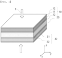
- FIG. 2 is a schematic view of the all-solid-state battery according to the present invention.
- the positive electrode 100 may be constituted by a positive electrode current collector 110 having a thickness of less than 5 um, wherein the positive electrode current collector 110 may be disposed so as to directly face the solid electrolyte layer 200, and the negative electrode may be constituted by a negative electrode current collector 300 having a thickness of less than 5 um, wherein the positive electrode current collector 300 may be disposed so as to directly face the solid electrolyte layer 200.
- both the positive electrode 100 and the negative electrode may each be constituted by an electrode current collector having a thickness of less than 5 um, wherein the electrode current collector may be disposed so as to directly face the solid electrolyte layer 200.
- a thin film current collector is used for only the negative electrode with reference to FIG. 2 , although no thin film current collector may be used for both the positive electrode and the negative electrode. It is obvious that the thin film current collector may be applied to the positive electrode.
- the all-solid-state battery according to the present invention is constituted by a positive electrode 100 including a positive electrode current collector 110 and a positive electrode active material layer 120 formed on at least one surface thereof by coating, a solid electrolyte layer 200, and a negative electrode constituted by a negative electrode current collector 300.
- the positive electrode may include a positive electrode current collector 110 and a positive electrode active material 120 provided so as to face the solid electrolyte layer 200
- the negative electrode may be constituted by a negative electrode active material layer applied to at least one surface of the negative electrode current collector 300.
- both the positive electrode and the negative electrode may each be constituted by an electrode current collector.
- the positive electrode 100 may be manufactured using a method of applying a positive electrode mixture of a positive electrode active material constituted by positive electrode active material particles, a conductive agent, and a binder to the positive electrode current collector 110 to form a positive electrode active material 120.
- a filler may be further added to the positive electrode mixture as needed.
- only the positive electrode current collector 110 may be used for the positive electrode, unlike FIG. 2 .
- the positive electrode current collector 110 is manufactured so as to have a thickness of 3 um to 500 um. In the case in which only the positive electrode current collector 110 is thermally treated together with the solid electrolyte layer, however, the thickness of the positive electrode current collector 110 may be less than 5 ⁇ m.
- the positive electrode current collector 110 is not particularly restricted as long as the positive electrode current collector exhibits high conductivity while the positive electrode current collector does not induce any chemical change in a battery to which the positive electrode current collector is applied.
- the positive electrode current collector may be made of stainless steel, aluminum, nickel, or titanium.
- the positive electrode current collector may be made of aluminum or stainless steel, the surface of which is treated with carbon, nickel, titanium, or silver.
- aluminum may be used.
- the current collector may have a micro-scale uneven pattern formed on the surface thereof so as to increase the force of adhesion to the positive electrode active material.
- the positive electrode current collector may be configured in any of various forms, such as a film, a sheet, a foil, a net, a porous body, a foam body, and a non-woven fabric body.
- the positive electrode active material layer 120 may be located on at least one surface of the positive electrode current collector 110. In the case in which the positive electrode current collector 110 is replaced with the current collector according to the present invention, the positive electrode active material layer 120 may be located at only the surface of the positive electrode current collector 110 that faces the solid electrolyte layer 200.
- the conductive agent is generally added so that the conductive agent accounts for 0.1 weight% to 30 weight% based on the total weight of the mixture including the positive electrode active material.
- the conductive agent is not particularly restricted as long as the conductive agent exhibits high conductivity without inducing any chemical change in a battery to which the conductive agent is applied.
- graphite such as natural graphite or artificial graphite
- carbon black such as acetylene black, Ketjen black, channel black, furnace black, lamp black, or thermal black
- conductive fiber such as carbon fiber or metallic fiber
- metallic powder such as carbon fluoride powder, aluminum powder, or nickel powder
- conductive whisker such as zinc oxide or potassium titanate
- a conductive metal oxide such as titanium oxide
- a conductive material such as a polyphenylene derivative
- the binder which is included in the positive electrode 100, is a component assisting in binding between the active material and the conductive agent and in binding with the current collector.
- the binder is generally added in an amount of 0.1 weight% to 30 weight% based on the total weight of the mixture including the positive electrode active material.
- binder there may be used polyvinylidene fluoride, polyvinyl alcohol, carboxymethylcellulose (CMC), starch, hydroxypropylcellulose, regenerated cellulose, polyvinyl pyrrolidone, tetrafluoroethylene, polyethylene, polypropylene, ethylene-propylene-diene terpolymer, sulfonated ethylene-propylene-diene termonomer, styrene butadiene rubber, fluoro rubber, and various copolymers.
- CMC carboxymethylcellulose
- an organic solid electrolyte or an inorganic solid electrolyte may be used for the solid electrolyte layer 200.
- the present invention is not limited thereto.
- the solid electrolyte layer 200 may further include a binder, such as polytetrafluoroethylene (PTFE).
- PTFE polytetrafluoroethylene
- a polyethylene derivative, a polyethylene oxide derivative, a polypropylene oxide derivative, a phosphoric acid ester polymer, poly agitation lysine, polyester sulfide, polyvinyl alcohol, polyvinylidene fluoride, or a polymer containing an ionic dissociation group may be used as the organic solid electrolyte.
- the inorganic solid electrolyte may be a sulfide-based solid electrolyte or an oxide-based solid electrolyte.
- a nitride or halide of Li such as Li 6.25 La 3 Zr 2 A l0.25 O 12 , Li 3 PO 4 , Li 3 +xPO 4 -xN x (LiPON), Li 3 N, LiI, Li 5 NI 2 , Li 3 N-LiI-LiOH, LiSiO 4 , LiSiO 4 -LiI-LiOH, Li 2 SiS 3 , Li 4 SiO 4 , or Li 4 SiO 4 -LiI-LiOH, may be used as the oxide-based solid electrolyte.
- the sulfide-based solid electrolyte is not particularly restricted, and all known sulfide-based materials used in the lithium battery field may be available. Products on the market may be used as the sulfide-based materials, or amorphous sulfide-based materials may be crystallized to manufacture the sulfide-based materials. For example, a crystalline sulfide-based solid electrolyte, an amorphous sulfide-based solid electrolyte, or a mixture thereof may be used as the sulfide-based solid electrolyte. There are a sulfur-halogen compound, a sulfur-germanium compound, and a sulfur-silicon compound as examples of available composite compounds.
- a sulfide such as SiS 2 , GeS 2 , or B 2 S 3 , may be included, and Li 3 PO 4 , halogen, or a halogen compound may be added.
- a sulfide-based electrolyte capable of implementing a lithium ion conductivity of 10 -4 S/cm or more is used.
- Li 6 PS 5 Cl LPSCl
- Thio-LISICON(Li 3.25 Ge 0.25 P 0.75 S 4 ) Li 2 S-P 2 S 5 -LiCl, Li 2 S-SiS 2 , LiI-Li 2 S-SiS 2 , LiI-Li 2 S-P 2 S 5 , LiI-Li 2 S-P 2 O 5 , LiI-Li 3 PO 4 -P 2 S 5 , Li 2 S-P 2 S 5 , Li 3 PS 4 , Li 7 P 3 S 11 , LiI-Li 2 S-B 2 S 3 , Li 3 PO 4 -Li 2 S-Si 2 S, Li 3 PO 4 -Li 2 S-SiS 2 , LiPO 4 -Li 2 S-SiS, Li 10 GeP 2 S 12 , Li 9.54 Si 1.74 P 1.44 S 11.7 Cl 0.3 , and Li 7 P 3 S 11 are included.
- the negative electrode according to the present invention may be constituted by only the negative electrode current collector 300.
- a negative electrode having a negative electrode active material applied to at least one surface of the negative electrode current collector 300 may be used.
- the negative electrode current collector 300 is generally manufactured so as to have a thickness of 3 um to 500 um.
- the negative electrode current collector 300 is not particularly restricted, as long as the negative electrode current collector exhibits high conductivity while the negative electrode current collector does not induce any chemical change in a battery to which the negative electrode current collector is applied.
- the negative electrode current collector may be made of copper, stainless steel, aluminum, nickel, titanium, or plastic carbon.
- the negative electrode current collector may be made of copper or stainless steel, the surface of which is treated with carbon, nickel, titanium, or silver, or an aluminum-cadmium alloy.
- the negative electrode current collector may have a micro-scale uneven pattern formed on the surface thereof so as to increase the force of adhesion of the negative electrode active material, in the same manner as the positive electrode current collector 110.
- the negative electrode current collector may be configured in any of various forms, such as a film, a sheet, a foil, a net, a porous body, a foam body, and a non-woven fabric body.
- the negative electrode active material for example, there may be used carbon, such as a non-graphitizing carbon or a graphite-based carbon; a metal composite oxide, such as Li x Fe 2 O 3 (0 ⁇ x ⁇ 1), Li x WO 2 (0 ⁇ x ⁇ 1), Sn x Me 1-x Me' y O z (Me: Mn, Fe, Pb, Ge; Me': Al, B, P, Si, Group 1, 2, and 3 elements of the periodic table, halogen; 0 ⁇ x ⁇ 1; 1 ⁇ y ⁇ 3; 1 ⁇ z ⁇ 8); lithium metal; a lithium alloy; a silicon-based alloy; a tin-based alloy; a metal oxide, such as SnO, SnO 2 , PbO, PbO 2 , Pb 2 O 3 , Pb 3 O 4 , Sb 2 O 3 , Sb 2 O 4 , Sb 2 O 5 , GeO, GeO 2 , Bi 2 O 3 , Bi 2 O 4 , or Bi 2 O 5 ;
- the negative electrode current collector 300 has a thickness of less than 5 um, and the negative electrode current collector 300 is disposed so as to directly face the solid electrolyte layer 200.
- the negative electrode current collector 300 may include a metal with high affinity for lithium.
- the metal with high affinity for lithium may be at least one selected from the group consisting of metals, including Au, Ag, Pt, Zn, Si, and Mg, and metal oxides, including CuO, ZnO, CoO, and MnO.
- the negative electrode current collector 300 includes a metal with high affinity for lithium, it is possible to adjust the position at which lithium dendrites are formed in the all-solid-state battery.
- the negative electrode current collector 300 may be thermally treated together with the solid electrolyte layer 200. In the case in which the negative electrode current collector 300 is thermally treated together with the solid electrolyte layer 200, interfacial resistance between the negative electrode current collector 300 and the solid electrolyte layer 200 is reduced. Since the negative electrode current collector 300 is separately formed and is then thermally treated together with the solid electrolyte layer 200, the negative electrode current collector 300 and the solid electrolyte layer 200 do not react with each other. Of course, the negative electrode current collector 300 may be directly deposited on the solid electrolyte layer 200.
- the positive electrode current collector 110 or the negative electrode current collector 300 may include no lithium metal.
- the reason for this is that, in consideration of the fact that the thickness of the positive electrode current collector 110 or the negative electrode current collector 300 is less than 5 ⁇ m, the solid electrolyte layer 200 may be damaged even though formation of lithium dendrites is adjusted, and therefore short circuit may occur. Consequently, the all-solid-state battery may be an all-solid-state battery that does not use lithium, like a nickel-cadmium battery, a nickel-manganese battery, a nickel-hydride battery, or a metal-air battery.
- FIG. 3 is a schematic view of an all-solid-state battery manufacturing method according to the present invention.
- the all-solid-state battery manufacturing method includes S1) a step of depositing a metal 310 for current collectors on a release film 320 to form a current collector, S2) a step of transferring the current collector of step S1) to a solid electrolyte layer 200 and performing heat treatment to form an electrode assembly, and S3) a step of removing the release film 320 from the electrode assembly.
- the metal used for the positive electrode current collector or the negative electrode current collector may be used as the metal 310 for current collectors.
- the metal used for the positive electrode current collector and the metal used for the negative electrode current collector that can be used as the metal 310 for current collectors have been described above, and therefore a description thereof will be omitted.
- release films may be used as the release film 320.
- any release film may be used as long as the release film 320 is made of a material that has low surface roughness and is capable of being easily peeled such that the release film 320 is not damaged when the metal 310 for current collectors is deposited and no residual is left when the metal 310 for current collectors is peeled.
- the release film 320 may be made of a synthetic resin, such as polyethylene, polypropylene, an ethylene-vinyl acetate copolymer, an ethylene-vinyl alcohol copolymer, or polyethylene terephthalate, or metal foil.
- the surface of the release film 320 that faces at least the metal 310 for current collectors may be coated or treated such that no residual is left when the metal 310 for current collectors is peeled.
- Surface reforming treatment such as plasma treatment or sulfonation treatment, or peeling treatment, such as silicone treatment, long cyclic alkyl treatment, or fluorine treatment, may be used as an example of the surface treatment.
- the release film 320 may be made of a material that is evaporated by heat treatment such that S3) the step of removing the release film 320 from the electrode assembly is not performed.
- adhesive forces at opposite surfaces of the release film 320 may be different from each other such that a process of peeling the metal 310 for current collectors is easily performed.
- the adhesive force at the surface of the release film that faces the metal 310 for current collectors may be lower than the adhesive force at the opposite surface of the release film.
- Deposition in step S1) may be performed using a vacuum deposition method, a chemical deposition method, a chemical vapor deposition method, a physical deposition method, a physical vapor deposition method, a thermal deposition method, an electron-beam evaporation method, or a sputtering method.
- a vacuum deposition method a chemical deposition method, a chemical vapor deposition method, a physical deposition method, a physical vapor deposition method, a thermal deposition method, an electron-beam evaporation method, or a sputtering method.
- the present invention is not limited thereto, and various deposition methods used in the art to which the present invention pertains may be used.
- step S2 the current collector is transferred to the solid electrolyte layer 200 and is then thermally treated to form an electrode assembly.
- transfer and heat treatment may be simultaneously performed. Transfer may be performed using a roll press. At this time, the roll press may simultaneously perform heating and pressurization.
- the temperature applied to the current collector and the solid electrolyte layer 200 may be 40°C to 200°C, specifically 100°C to 150°C.
- the temperature is lower than 40°C, a desired extent of contact between the current collector and the solid electrolyte layer 200 is not achieved, which is undesirable.
- adhesive force may be reduced or the solid electrolyte layer 200 may be deformed due to material denaturation due to side reaction or reduction in performance of the binder, which is also undesirable.
- Heat treatment time may be about 6 hours to 48 hours, specifically about 12 hours to 24 hours. In the case in which the time is less than 6 hours, an effect of improvement due to heat treatment may be insignificant, which is undesirable. In the case in which the time is greater than 48 hours, processability may be reduced, which is also undesirable.
- Pressure for pressurization may be about 1 ton to about 3 ton, specifically about 1.5 ton to about 2 ton. In the case in which the pressure is greater than 3 ton, the solid electrolyte layer may be damaged. In the case in which the pressure is less than 1 ton, an effect of reducing interfacial resistance between the current collector and the solid electrolyte layer 200 may be insignificant.
- Pressurization time may be about 1 minute to about 24 hours.
- the most preferable pressurization time range may be about 1.5 minutes to about 2.5 minutes.
- the pressurization time is greater than 24 hours, the solid electrolyte layer 200 may be structurally deformed.
- the pressurization time is less than a minute, an effect of reducing interfacial resistance between the current collector and the solid electrolyte layer 200 may be insignificant.
- step S3) the release film 320 is removed from the electrode assembly.
- the metal 310 for current collectors may be peeled in the state in which the release film 320 is attached to a roll or a substrate that has high force of adhesion with the release film 320.
- the metal 310 for current collectors may be peeled due to a difference in adhesive force between the surface of the release film 320 that faces the metal 310 for current collectors and the opposite surface of the release film.
- the release film 320 may be made of a material that is evaporated by heat treatment, as described above, such that the release film is evaporated by heat treatment in step S2).
- Electrical conductivity may be calculated as the reciprocal of resistivity ⁇ cal . It can be seen that the smaller the value of resistivity, the higher the electrical conductivity.
- ⁇ bulk indicates the inherent resistivity value of each of the materials used in Manufacturing Example 1 to Manufacturing Example 5.
- R s ( ⁇ /t, ⁇ /sq) Thickness ( ⁇ m) ⁇ cal ( ⁇ cm) ⁇ bulk ( ⁇ cm) Manufacturing Example 1 1.759X10 -2 1 1.76 1.62 Manufacturing Example 2 0.875X10 -2 2 1.75 1.62 Manufacturing Example 3 2.534X10 -2 1 2.53 2.4 Manufacturing Example 4 0.735X10 -2 11 8.09 7.24 Manufacturing Example 5 7.43X10 -2 10 74.3 72
- resistivity ⁇ cal of each of the materials according to Manufacturing Example 1 to Manufacturing Example 5 calculated using the above equation is similar to inherent resistivity ⁇ bulk thereof, whereby reliability of the calculated value of resistivity ⁇ cal is high.
- Manufacturing Examples 1 and 2 in which silver with high affinity for lithium was formed as a thin film, have more similar average resistance values than Manufacturing Example 4, in which gold was formed as a thin film, when compared to average resistance of Manufacturing Example 4, in which a general nickel current collector was used.
- Manufacturing Example 1 in which silver having a thickness of 1 ⁇ m was deposited on the PET release film, has much lower average resistance than the SUS304 current collector of Manufacturing Example 5 although the thickness of silver is very small, and therefore Manufacturing Example 1 exhibits very excellent electrical conductivity.
- each of silver coated on the PET release film and gold coated on the PET release film is capable of serving as a current collector like nickel or SUS304.
- the solid electrolyte layer was manufactured by dispersing and stirring argyrodite (Li 6 PS 5 Cl), as a solid electrolyte, and PTFE, as a binder, in anisole in a weight ratio of 95:5 to form a solid electrolyte layer slurry, coating a PET release film with the solid electrolyte layer slurry, and drying the solid electrolyte layer slurry under vacuum at 100°C for 12 hours.
- argyrodite Li 6 PS 5 Cl
- PTFE a binder
- Experimental Example 3 experiments were conducted on an all-solid-state battery including a positive electrode, a solid electrolyte layer, and a negative electrode according to each of Example 1, Comparative Example 1, and Comparative Example 2 based on Experimental Example 1 and Experimental Example 2.
- the positive electrode slurry was applied to an aluminum current collector having a thickness of 14 um using a doctor blade, and was dried under vacuum at 100°C for 12 hours to manufacture a positive electrode.
- Argyrodite (Li 6 PS 5 Cl), as a solid electrolyte, and PTFE, as a binder polymer, were dispersed and stirred in anisole in a weight ratio of 95:5 to manufacture a solid electrolyte layer slurry.
- the solid electrolyte layer slurry was applied to a PET release film, and was dried under vacuum at 100°C for 12 hours to manufacture a solid electrolyte layer.
- the positive electrode, the solid electrolyte layer, and a negative electrode according to each of Example 1, Comparative Example 1, and Comparative Example 2 were sequentially stacked to manufacture a battery.
- Example 1 an electrode assembly was manufactured using the negative electrode according to Manufacturing Example 1, and the electrode assembly was thermally treated at 100°C for 12 hours.
- Comparative Example 1 a battery was manufactured in the same manner as Example 1 except that a stack of nickel having a thickness of 11 um according to Manufacturing Example 4 was used as the negative electrode.
- the thickness of the current collector according to Example 1 is only about 9% of the thickness of the current collector according to Comparative Example 1, and therefore the thickness of a cell according to Example 1 is less than the thickness of a cell according to Comparative Example 1.
- the thickness of the positive electrode is 50 um and the thickness of the solid electrolyte layer is 30 ⁇ m, energy density of the cell according to Example 1 is 12.3% higher than energy density of the cell according to Comparative Example 1.
- the present invention provides a battery module or a battery pack including the all-solid-state battery and a device including the battery pack.
- the battery pack and the device are well known in the art to which the present invention pertains, and thus a detailed description thereof will be omitted.
- the device may be a laptop computer, a netbook computer, a tablet PC, a mobile phone, an MP3 player, a wearable electronic device, a power tool, an electric vehicle (EV), a hybrid electric vehicle (HEV), a plug-in hybrid electric vehicle (PHEV), an electric bicycle (E-bike), an electric scooter (E-scooter), an electric golf cart, or an energy storage system.
- EV electric vehicle
- HEV hybrid electric vehicle
- PHEV plug-in hybrid electric vehicle
- E-bike electric bicycle
- E-scooter electric golf cart
- the present invention is not limited thereto.
- an all-solid-state battery according to the present invention, a thin film current collector is thermally treated together with a solid electrolyte layer, whereby interfacial resistance is reduced, and therefore performance of the all-solid-state battery is improved.
- the thickness of the current collector is small, whereby the ratio of capacity to size of the all-solid-state battery is increased.
Landscapes
- Chemical & Material Sciences (AREA)
- Engineering & Computer Science (AREA)
- Chemical Kinetics & Catalysis (AREA)
- Electrochemistry (AREA)
- General Chemical & Material Sciences (AREA)
- Manufacturing & Machinery (AREA)
- Materials Engineering (AREA)
- Physics & Mathematics (AREA)
- General Physics & Mathematics (AREA)
- Inorganic Chemistry (AREA)
- Condensed Matter Physics & Semiconductors (AREA)
- Secondary Cells (AREA)
- Cell Electrode Carriers And Collectors (AREA)
- Battery Electrode And Active Subsutance (AREA)
Abstract
Description
- This application claims the benefit of priority to
Korean Patent Application No. 2020-0091625 filed on July 23, 2020 - The present invention relates to an all-solid-state battery including a thin film current collector and a method of manufacturing the same. More particularly, the present invention relates to an all-solid-state battery including a thin film current collector, wherein interfacial resistance between the current collector and a solid electrolyte is reduced while the overall capacity of the all-solid-state battery is increased as the result of using the thin film current collector, and a method of manufacturing the same.
- The lifespan of a secondary battery using an electrolytic solution is reduced due to consumption of the electrolytic solution during charging and discharging, or the secondary battery overheats or explodes due to leakage or combustion of the electrolytic solution.
- In order to improve safety of the secondary battery, various methods, such as provision of a safety device, such as a fuse or a protection circuit, have been considered. In order to solve the above problems, an all-solid-state battery using a solid electrolyte instead of a liquid electrolytic solution has been proposed.
- Unlike the conventional secondary battery, the all-solid-state battery is configured such that a positive electrode and a negative electrode are formed on opposite surfaces of a solid electrolyte layer including the solid electrolyte and the solid electrolyte layer also serves as a separator.
- Since the all-solid-state battery uses the solid electrolyte instead of the liquid electrolytic solution, there is no evaporation of the electrolytic solution due to temperature change or no leakage of the electrolytic solution due to external impact, whereby the all-solid-state battery is safe against explosion and outbreak of fire. However, since the all-solid-state battery has lower ionic conductivity than the secondary battery using the liquid electrolyte and interfacial formation between the positive electrode, the negative electrode, and the solid electrolyte layer is not easily achieved, interfacial resistance is high. The all-solid-state battery has shortcomings of short lifespan and low output due to such problems.
-
FIG. 1 is a schematic view of a conventional all-solid-state battery. - As can be seen from
FIG. 1 , the conventional lithium secondary battery includes apositive electrode 10 including a positive electrodecurrent collector 11 and a positive electrodeactive material layer 12 formed on opposite surfaces thereof by coating, asolid electrolyte layer 20, and anegative electrode 30 including a negativeelectrode current collector 31 and a negative electrodeactive material layer 32 formed on opposite surfaces thereof by coating. In order to increase overall capacity of the lithium secondary battery, the negative electrode may be used as a lithium plating and stripping mechanism through a negative electrode current collector alone or using lithium metal without a separate negative electrodeactive material layer 32, unlikeFIG. 1 . - In the conventional lithium secondary battery, pressure F is applied to the battery from above and below in order to reduce interfacial resistance between the
positive electrode 10 and thesolid electrolyte layer 20 and between thesolid electrolyte layer 20 and thenegative electrode 30. In the case in which thepositive electrode 10, thesolid electrolyte layer 20, and thenegative electrode 30 are not uniform, it is difficult to reduce interfacial resistance merely through pressurization, and short circuit due to growth of lithium dendrites may occur at a portion having different interfacial resistance during charging. In particular, the amount of lithium that is deposited during charging is increased in proportion to an increase in capacity of the positive electrode to achieve high energy density, whereby a short circuit occurrence probability is increased. - Meanwhile, research on a battery using Li plating/stripping has been continuously conducted in order to increase energy density of a battery. In general, a current collector that is used has a thickness of about 10 um, and therefore it is necessary to further reduce the thickness of the current collector through an additional thinning process in order to increase energy density.
- In Patent Document 1, a stack including a positive electrode, a solid electrolyte layer, and a negative electrode is pressurized in order to improve conductivity, electron conductivity, and lithium ion conductivity. However, this patent document does not disclose preventing a cell short circuit phenomenon of a unit cell due to lithium dendrites during charging.
- In Patent Document 2, a stack including a positive electrode, a solid electrolyte layer, and a negative electrode is pressurized in order to reduce interfacial resistance. However, this patent document does not disclose reducing stress due to lithium dendrites during charging in order to improve safety of a unit cell.
-
- (Patent Document 1)
Japanese Patent Application Publication No. 2018-181451 (2018.11.15 - (Patent Document 2)
Japanese Patent Application Publication No. 2019-200890 (2019.11.21 - The present invention has been made in view of the above problems, and it is an object of the present invention to reduce interfacial resistance between an electrode having a current collector and a solid electrolyte layer while using a thin film current collector as the current collector.
- It is another object of the present invention to increase the ratio of capacity to size of a battery through the use of the thin film current collector.
- In order to accomplish the above objects, an all-solid-state battery according to the present invention includes a positive electrode, a solid electrolyte layer, and a negative electrode, wherein the positive electrode or the negative electrode comprises a current collector having a thickness of less than 5 um, and the current collector directly faces the solid electrolyte layer.
- The current collector may include a metal with high affinity for lithium.
- At this time, the metal with high affinity for lithium may be at least one selected from the group consisting of metals, comprising Au, Ag, Pt, Zn, Si and Mg, and metal oxides, comprising CuO, ZnO, CoO and MnO.
- At this time, it is preferable that the current collector may not include lithium metal.
- The current collector may be thermally treated together with the solid electrolyte layer.
- In addition, the current collector may be formed through a deposition and transfer process.
- The all-solid-state battery may be a battery that does not use lithium, like a nickel-cadmium battery, a nickel-manganese battery, a nickel-hydride battery, or a metal-air battery.
- The present invention provides a method of manufacturing the all-solid-state battery, the method including S1) depositing a metal for current collectors on a release film to form a current collector and S2) transferring the current collector of step S1) to a solid electrolyte layer and performing heat treatment to form an electrode assembly.
- In addition, the method may include removing the release film after step S2) or before heat treatment of step S2).
- In addition, in step S2), transferring and performing heat treatment may be simultaneously performed.
- The surface of the release film on which the metal is deposited may be coated or surface treated.
- Depositing in step S1) may be performed by utilizing one of a vacuum deposition method, a chemical deposition method, a chemical vapor deposition method, and a physical deposition method.
- The present invention provides a battery module or a battery pack including the all-solid-state battery mentioned above. In addition, the present invention provides a device having the all-solid-state battery mounted therein.
- In the present invention, one or more constructions that do not conflict with each other may be selected and combined from among the above constructions.
- As is apparent from the above description, in an all-solid-state battery according to the present invention, a thin film current collector is thermally treated together with a solid electrolyte layer, whereby interfacial resistance is reduced, and therefore performance of the all-solid-state battery is improved.
- In addition, the thickness of the current collector is small, whereby the ratio of capacity to size of the all-solid-state battery is increased.
-
-
FIG. 1 is a schematic view of a conventional all-solid-state battery. -
FIG. 2 is a schematic view of an all-solid-state battery according to the present invention. -
FIG. 3 is a schematic view of an all-solid-state battery manufacturing method according to the present invention. - Now, preferred embodiments of the present invention will be described in detail with reference to the accompanying drawings such that the preferred embodiments of the present invention can be easily implemented by a person having ordinary skill in the art to which the present invention pertains. In describing the principle of operation of the preferred embodiments of the present invention in detail, however, a detailed description of known functions and configurations incorporated herein will be omitted when the same may obscure the subject matter of the present invention.
- In addition, the same reference numbers will be used throughout the drawings to refer to parts that perform similar functions or operations. In the case in which one part is said to be connected to another part throughout the specification, not only may the one part be directly connected to the other part, but also, the one part may be indirectly connected to the other part via a further part. In addition, that a certain element is included does not mean that other elements are excluded, but means that such elements may be further included unless mentioned otherwise.
- In addition, a description to embody elements through limitation or addition may be applied to all inventions, unless particularly restricted, and does not limit a specific invention.
- Also, in the description of the invention and the claims of the present application, singular forms are intended to include plural forms unless mentioned otherwise.
- Also, in the description of the invention and the claims of the present application, "or" includes "and" unless mentioned otherwise. Therefore, "including A or B" means three cases, namely, the case including A, the case including B, and the case including A and B.
- In addition, all numeric ranges include the lowest value, the highest value, and all intermediate values therebetween unless the context clearly indicates otherwise.
- An all-solid-state battery according to the present invention includes a positive electrode, a solid electrolyte layer, and a negative electrode, wherein the positive electrode or the negative electrode is constituted by a current collector having a thickness of less than 5 um, and the current collector is disposed so as to directly face the solid electrolyte layer.
-
FIG. 2 is a schematic view of the all-solid-state battery according to the present invention. - In the all-solid-state battery according to the present invention, the
positive electrode 100 may be constituted by a positive electrodecurrent collector 110 having a thickness of less than 5 um, wherein the positive electrodecurrent collector 110 may be disposed so as to directly face thesolid electrolyte layer 200, and the negative electrode may be constituted by a negative electrodecurrent collector 300 having a thickness of less than 5 um, wherein the positive electrodecurrent collector 300 may be disposed so as to directly face thesolid electrolyte layer 200. Alternatively, both thepositive electrode 100 and the negative electrode may each be constituted by an electrode current collector having a thickness of less than 5 um, wherein the electrode current collector may be disposed so as to directly face thesolid electrolyte layer 200. Hereinafter, a description will be given based on the case in which a thin film current collector is used for only the negative electrode with reference toFIG. 2 , although no thin film current collector may be used for both the positive electrode and the negative electrode. It is obvious that the thin film current collector may be applied to the positive electrode. - As shown in
FIG. 2 , the all-solid-state battery according to the present invention is constituted by apositive electrode 100 including a positive electrodecurrent collector 110 and a positive electrodeactive material layer 120 formed on at least one surface thereof by coating, asolid electrolyte layer 200, and a negative electrode constituted by a negative electrodecurrent collector 300. In one case, the positive electrode may include a positive electrodecurrent collector 110 and a positive electrodeactive material 120 provided so as to face thesolid electrolyte layer 200, and the negative electrode may be constituted by a negative electrode active material layer applied to at least one surface of the negative electrodecurrent collector 300. In another case, both the positive electrode and the negative electrode may each be constituted by an electrode current collector. - For example, the
positive electrode 100 may be manufactured using a method of applying a positive electrode mixture of a positive electrode active material constituted by positive electrode active material particles, a conductive agent, and a binder to the positive electrodecurrent collector 110 to form a positive electrodeactive material 120. A filler may be further added to the positive electrode mixture as needed. In addition, only the positive electrodecurrent collector 110 may be used for the positive electrode, unlikeFIG. 2 . - In general, the positive electrode
current collector 110 is manufactured so as to have a thickness of 3 um to 500 um. In the case in which only the positive electrodecurrent collector 110 is thermally treated together with the solid electrolyte layer, however, the thickness of the positive electrodecurrent collector 110 may be less than 5 µm. - The positive electrode
current collector 110 is not particularly restricted as long as the positive electrode current collector exhibits high conductivity while the positive electrode current collector does not induce any chemical change in a battery to which the positive electrode current collector is applied. For example, the positive electrode current collector may be made of stainless steel, aluminum, nickel, or titanium. Alternatively, the positive electrode current collector may be made of aluminum or stainless steel, the surface of which is treated with carbon, nickel, titanium, or silver. Specifically, aluminum may be used. The current collector may have a micro-scale uneven pattern formed on the surface thereof so as to increase the force of adhesion to the positive electrode active material. The positive electrode current collector may be configured in any of various forms, such as a film, a sheet, a foil, a net, a porous body, a foam body, and a non-woven fabric body. - In addition to the positive electrode active material particles, the positive electrode active material included in the positive electrode active material layer 120 may be constituted, for example, by a layered compound, such as a lithium nickel oxide (LiNiO2), or a compound substituted with one or more transition metals; a lithium manganese oxide represented by the chemical formula Li1+xMn2-xO4 (where x = 0 to 0.33) or a lithium manganese oxide, such as LiMnO3, LiMn2O3, or LiMnO2; a lithium copper oxide (Li2CuO2); a vanadium oxide, such as LiV3O8, LiFe3O4, V2O5, or Cu2V2O7; an Ni-sited lithium nickel oxide represented by the chemical formula LiNi1-xMxO2 (where M = Co, Mn, Al, Cu, Fe, Mg, B, or Ga, and x = 0.01 to 0.3); a lithium manganese composite oxide represented by the chemical formula LiMn2-xMxO2 (where M = Co, Ni, Fe, Cr, Zn, or Ta, and x = 0.01 to 0.1) or the chemical formula Li2Mn3MO8 (where M = Fe, Co, Ni, Cu, or Zn); LiMn2O4 in which a portion of Li in the chemical formula is replaced by alkaline earth metal ions; a disulfide compound; or Fe2(MoO4)3. However, the present invention is not limited thereto.
- The positive electrode
active material layer 120 may be located on at least one surface of the positive electrodecurrent collector 110. In the case in which the positive electrodecurrent collector 110 is replaced with the current collector according to the present invention, the positive electrodeactive material layer 120 may be located at only the surface of the positive electrodecurrent collector 110 that faces thesolid electrolyte layer 200. - The conductive agent is generally added so that the conductive agent accounts for 0.1 weight% to 30 weight% based on the total weight of the mixture including the positive electrode active material. The conductive agent is not particularly restricted as long as the conductive agent exhibits high conductivity without inducing any chemical change in a battery to which the conductive agent is applied. For example, graphite, such as natural graphite or artificial graphite; carbon black, such as acetylene black, Ketjen black, channel black, furnace black, lamp black, or thermal black; conductive fiber, such as carbon fiber or metallic fiber; metallic powder, such as carbon fluoride powder, aluminum powder, or nickel powder; conductive whisker, such as zinc oxide or potassium titanate; a conductive metal oxide, such as titanium oxide; or a conductive material, such as a polyphenylene derivative, may be used as the conductive agent.
- The binder, which is included in the
positive electrode 100, is a component assisting in binding between the active material and the conductive agent and in binding with the current collector. The binder is generally added in an amount of 0.1 weight% to 30 weight% based on the total weight of the mixture including the positive electrode active material. As examples of the binder, there may be used polyvinylidene fluoride, polyvinyl alcohol, carboxymethylcellulose (CMC), starch, hydroxypropylcellulose, regenerated cellulose, polyvinyl pyrrolidone, tetrafluoroethylene, polyethylene, polypropylene, ethylene-propylene-diene terpolymer, sulfonated ethylene-propylene-diene termonomer, styrene butadiene rubber, fluoro rubber, and various copolymers. - An organic solid electrolyte or an inorganic solid electrolyte may be used for the
solid electrolyte layer 200. However, the present invention is not limited thereto. In addition, thesolid electrolyte layer 200 may further include a binder, such as polytetrafluoroethylene (PTFE). - For example, a polyethylene derivative, a polyethylene oxide derivative, a polypropylene oxide derivative, a phosphoric acid ester polymer, poly agitation lysine, polyester sulfide, polyvinyl alcohol, polyvinylidene fluoride, or a polymer containing an ionic dissociation group may be used as the organic solid electrolyte.
- As an example, the inorganic solid electrolyte may be a sulfide-based solid electrolyte or an oxide-based solid electrolyte.
- For example, a nitride or halide of Li, such as Li6.25La3Zr2Al0.25O12, Li3PO4, Li3+xPO4-xNx(LiPON), Li3N, LiI, Li5NI2, Li3N-LiI-LiOH, LiSiO4, LiSiO4-LiI-LiOH, Li2SiS3, Li4SiO4, or Li4SiO4-LiI-LiOH, may be used as the oxide-based solid electrolyte.
- In the present invention, the sulfide-based solid electrolyte is not particularly restricted, and all known sulfide-based materials used in the lithium battery field may be available. Products on the market may be used as the sulfide-based materials, or amorphous sulfide-based materials may be crystallized to manufacture the sulfide-based materials. For example, a crystalline sulfide-based solid electrolyte, an amorphous sulfide-based solid electrolyte, or a mixture thereof may be used as the sulfide-based solid electrolyte. There are a sulfur-halogen compound, a sulfur-germanium compound, and a sulfur-silicon compound as examples of available composite compounds. Specifically, a sulfide, such as SiS2, GeS2, or B2S3, may be included, and Li3PO4, halogen, or a halogen compound may be added. Preferably, a sulfide-based electrolyte capable of implementing a lithium ion conductivity of 10-4 S/cm or more is used.
- Typically, Li6PS5Cl (LPSCl), Thio-LISICON(Li3.25Ge0.25P0.75S4), Li2S-P2S5-LiCl, Li2S-SiS2, LiI-Li2S-SiS2, LiI-Li2S-P2S5, LiI-Li2S-P2O5, LiI-Li3PO4-P2S5, Li2S-P2S5, Li3PS4, Li7P3S11, LiI-Li2S-B2S3, Li3PO4-Li2S-Si2S, Li3PO4-Li2S-SiS2, LiPO4-Li2S-SiS, Li10GeP2S12, Li9.54Si1.74P1.44S11.7Cl0.3, and Li7P3S11 are included.
- The negative electrode according to the present invention may be constituted by only the negative electrode
current collector 300. Alternatively, in the case in which thepositive electrode 100 is constituted by only the positive electrodecurrent collector 110, a negative electrode having a negative electrode active material applied to at least one surface of the negative electrodecurrent collector 300 may be used. - In the case in which a negative electrode having a negative electrode active material applied to at least one surface of an negative electrode current collector is used as the negative electrode, the negative electrode
current collector 300 is generally manufactured so as to have a thickness of 3 um to 500 um. The negative electrodecurrent collector 300 is not particularly restricted, as long as the negative electrode current collector exhibits high conductivity while the negative electrode current collector does not induce any chemical change in a battery to which the negative electrode current collector is applied. For example, the negative electrode current collector may be made of copper, stainless steel, aluminum, nickel, titanium, or plastic carbon. Alternatively, the negative electrode current collector may be made of copper or stainless steel, the surface of which is treated with carbon, nickel, titanium, or silver, or an aluminum-cadmium alloy. In addition, the negative electrode current collector may have a micro-scale uneven pattern formed on the surface thereof so as to increase the force of adhesion of the negative electrode active material, in the same manner as the positive electrodecurrent collector 110. The negative electrode current collector may be configured in any of various forms, such as a film, a sheet, a foil, a net, a porous body, a foam body, and a non-woven fabric body. - As the negative electrode active material, for example, there may be used carbon, such as a non-graphitizing carbon or a graphite-based carbon; a metal composite oxide, such as LixFe2O3 (0≤x≤1), LixWO2 (0≤x≤1), SnxMe1-xMe'yOz (Me: Mn, Fe, Pb, Ge; Me': Al, B, P, Si, Group 1, 2, and 3 elements of the periodic table, halogen; 0<x≤1; 1≤y≤3; 1≤z≤8); lithium metal; a lithium alloy; a silicon-based alloy; a tin-based alloy; a metal oxide, such as SnO, SnO2, PbO, PbO2, Pb2O3, Pb3O4, Sb2O3, Sb2O4, Sb2O5, GeO, GeO2, Bi2O3, Bi2O4, or Bi2O5; a conductive polymer, such as polyacetylene; or a Li-Co-Ni based material.
- In the case in which only the negative electrode
current collector 300 is used for the negative electrode, the negative electrodecurrent collector 300 has a thickness of less than 5 um, and the negative electrodecurrent collector 300 is disposed so as to directly face thesolid electrolyte layer 200. - The negative electrode
current collector 300 may include a metal with high affinity for lithium. The metal with high affinity for lithium may be at least one selected from the group consisting of metals, including Au, Ag, Pt, Zn, Si, and Mg, and metal oxides, including CuO, ZnO, CoO, and MnO. - Since the negative electrode
current collector 300 includes a metal with high affinity for lithium, it is possible to adjust the position at which lithium dendrites are formed in the all-solid-state battery. - The negative electrode
current collector 300 may be thermally treated together with thesolid electrolyte layer 200. In the case in which the negative electrodecurrent collector 300 is thermally treated together with thesolid electrolyte layer 200, interfacial resistance between the negative electrodecurrent collector 300 and thesolid electrolyte layer 200 is reduced. Since the negative electrodecurrent collector 300 is separately formed and is then thermally treated together with thesolid electrolyte layer 200, the negative electrodecurrent collector 300 and thesolid electrolyte layer 200 do not react with each other. Of course, the negative electrodecurrent collector 300 may be directly deposited on thesolid electrolyte layer 200. - The positive electrode
current collector 110 or the negative electrodecurrent collector 300 may include no lithium metal. The reason for this is that, in consideration of the fact that the thickness of the positive electrodecurrent collector 110 or the negative electrodecurrent collector 300 is less than 5 µm, thesolid electrolyte layer 200 may be damaged even though formation of lithium dendrites is adjusted, and therefore short circuit may occur. Consequently, the all-solid-state battery may be an all-solid-state battery that does not use lithium, like a nickel-cadmium battery, a nickel-manganese battery, a nickel-hydride battery, or a metal-air battery. -
FIG. 3 is a schematic view of an all-solid-state battery manufacturing method according to the present invention. - As shown in
FIG. 3 , the all-solid-state battery manufacturing method according to the present invention includes S1) a step of depositing ametal 310 for current collectors on arelease film 320 to form a current collector, S2) a step of transferring the current collector of step S1) to asolid electrolyte layer 200 and performing heat treatment to form an electrode assembly, and S3) a step of removing therelease film 320 from the electrode assembly. - The metal used for the positive electrode current collector or the negative electrode current collector may be used as the
metal 310 for current collectors. The metal used for the positive electrode current collector and the metal used for the negative electrode current collector that can be used as themetal 310 for current collectors have been described above, and therefore a description thereof will be omitted. - All known release films may be used as the
release film 320. As an example, any release film may be used as long as therelease film 320 is made of a material that has low surface roughness and is capable of being easily peeled such that therelease film 320 is not damaged when themetal 310 for current collectors is deposited and no residual is left when themetal 310 for current collectors is peeled. For example, therelease film 320 may be made of a synthetic resin, such as polyethylene, polypropylene, an ethylene-vinyl acetate copolymer, an ethylene-vinyl alcohol copolymer, or polyethylene terephthalate, or metal foil. - The surface of the
release film 320 that faces at least themetal 310 for current collectors may be coated or treated such that no residual is left when themetal 310 for current collectors is peeled. Surface reforming treatment, such as plasma treatment or sulfonation treatment, or peeling treatment, such as silicone treatment, long cyclic alkyl treatment, or fluorine treatment, may be used as an example of the surface treatment. In addition, therelease film 320 may be made of a material that is evaporated by heat treatment such that S3) the step of removing therelease film 320 from the electrode assembly is not performed. - In addition, adhesive forces at opposite surfaces of the
release film 320 may be different from each other such that a process of peeling themetal 310 for current collectors is easily performed. The adhesive force at the surface of the release film that faces themetal 310 for current collectors may be lower than the adhesive force at the opposite surface of the release film. - Deposition in step S1) may be performed using a vacuum deposition method, a chemical deposition method, a chemical vapor deposition method, a physical deposition method, a physical vapor deposition method, a thermal deposition method, an electron-beam evaporation method, or a sputtering method. However, the present invention is not limited thereto, and various deposition methods used in the art to which the present invention pertains may be used.
- In step S2), the current collector is transferred to the
solid electrolyte layer 200 and is then thermally treated to form an electrode assembly. At this time, transfer and heat treatment may be simultaneously performed. Transfer may be performed using a roll press. At this time, the roll press may simultaneously perform heating and pressurization. - At this time, the temperature applied to the current collector and the
solid electrolyte layer 200 may be 40°C to 200°C, specifically 100°C to 150°C. In the case in which the temperature is lower than 40°C, a desired extent of contact between the current collector and thesolid electrolyte layer 200 is not achieved, which is undesirable. In the case in which the temperature is higher than 200°C, adhesive force may be reduced or thesolid electrolyte layer 200 may be deformed due to material denaturation due to side reaction or reduction in performance of the binder, which is also undesirable. - Heat treatment time may be about 6 hours to 48 hours, specifically about 12 hours to 24 hours. In the case in which the time is less than 6 hours, an effect of improvement due to heat treatment may be insignificant, which is undesirable. In the case in which the time is greater than 48 hours, processability may be reduced, which is also undesirable.
- Pressure for pressurization may be about 1 ton to about 3 ton, specifically about 1.5 ton to about 2 ton. In the case in which the pressure is greater than 3 ton, the solid electrolyte layer may be damaged. In the case in which the pressure is less than 1 ton, an effect of reducing interfacial resistance between the current collector and the
solid electrolyte layer 200 may be insignificant. - Pressurization time may be about 1 minute to about 24 hours. The most preferable pressurization time range may be about 1.5 minutes to about 2.5 minutes. In the case in which the pressurization time is greater than 24 hours, the
solid electrolyte layer 200 may be structurally deformed. In the case in which the pressurization time is less than a minute, an effect of reducing interfacial resistance between the current collector and thesolid electrolyte layer 200 may be insignificant. - In step S3), the
release film 320 is removed from the electrode assembly. Themetal 310 for current collectors may be peeled in the state in which therelease film 320 is attached to a roll or a substrate that has high force of adhesion with therelease film 320. Themetal 310 for current collectors may be peeled due to a difference in adhesive force between the surface of therelease film 320 that faces themetal 310 for current collectors and the opposite surface of the release film. In addition, therelease film 320 may be made of a material that is evaporated by heat treatment, as described above, such that the release film is evaporated by heat treatment in step S2). - Hereinafter, the present invention will be described based on comparison between Example according to the present invention and Comparative Examples according to the conventional art through Experimental Examples.
- Silver coated on a PET release film by deposition so as to have a thickness of 1 um (Manufacturing Example 1), silver coated on a PET release film by deposition so as to have a thickness of 2 um (Manufacturing Example 2), gold coated on a PET release film by deposition so as to have a thickness of 1 um (Manufacturing Example 3), non-deposited nickel foil having a thickness of 11 um (Manufacturing Example 4), and non-deposited SUS304 foil having a thickness of 10 um (Manufacturing Example 5) were compared with each other in terms of electrical conductivity, and the results are shown in Table 1 below. The electrical conductivity was measured for samples each having a size of 5x5 cm2 using a 4-point probe instrument. At this time, each sample was partitioned into 25 sections, the average resistance Rs value of values measured for the respective sections was obtained, and resistivity ρcal of each of the materials used in Manufacturing Example 1 to Manufacturing Example 5 was calculated using the following equation. The results are shown in Table 1 below.

- Electrical conductivity may be calculated as the reciprocal of resistivity ρcal. It can be seen that the smaller the value of resistivity, the higher the electrical conductivity.
- In Table 1 below, ρbulk indicates the inherent resistivity value of each of the materials used in Manufacturing Example 1 to Manufacturing Example 5.
[Table 1] Rs (ρ/t,Ω/sq) Thickness (µm) ρcal (µΩ·cm) ρbulk (µΩ·cm) Manufacturing Example 1 1.759X10⁻² 1 1.76 1.62 Manufacturing Example 2 0.875X10⁻² 2 1.75 1.62 Manufacturing Example 3 2.534X10⁻² 1 2.53 2.4 Manufacturing Example 4 0.735 X10 -211 8.09 7.24 Manufacturing Example 5 7.43 X10 -210 74.3 72 - Referring to Table 1 above, it can be seen that resistivity ρcal of each of the materials according to Manufacturing Example 1 to Manufacturing Example 5 calculated using the above equation is similar to inherent resistivity ρbulk thereof, whereby reliability of the calculated value of resistivity ρcal is high.
- As shown in Table 1, Manufacturing Examples 1 and 2, in which silver with high affinity for lithium was formed as a thin film, have more similar average resistance values than Manufacturing Example 4, in which gold was formed as a thin film, when compared to average resistance of Manufacturing Example 4, in which a general nickel current collector was used.
- In particular, Manufacturing Example 1, in which silver having a thickness of 1 µm was deposited on the PET release film, has much lower average resistance than the SUS304 current collector of Manufacturing Example 5 although the thickness of silver is very small, and therefore Manufacturing Example 1 exhibits very excellent electrical conductivity.
- Consequently, it can be seen that each of silver coated on the PET release film and gold coated on the PET release film is capable of serving as a current collector like nickel or SUS304.
- The current collector of Manufacturing Example 1 and a solid electrolyte layer were bonded to each other, and interfacial resistance therebetween was measured before heat treatment and after heat treatment under vacuum at 100°C for 12 hours. The results are shown in Table 2.
- The solid electrolyte layer was manufactured by dispersing and stirring argyrodite (Li6PS5Cl), as a solid electrolyte, and PTFE, as a binder, in anisole in a weight ratio of 95:5 to form a solid electrolyte layer slurry, coating a PET release film with the solid electrolyte layer slurry, and drying the solid electrolyte layer slurry under vacuum at 100°C for 12 hours.
[Table 2] Interfacial resistance (Ω) Before heat treatment 7.2 After heat treatment 1.7 - In Experimental Example 3, experiments were conducted on an all-solid-state battery including a positive electrode, a solid electrolyte layer, and a negative electrode according to each of Example 1, Comparative Example 1, and Comparative Example 2 based on Experimental Example 1 and Experimental Example 2.
- NCM811(LiNi0.8Co0.1Mn0.1O2), as a positive electrode active material, argyrodite (Li6PS5Cl), as a solid electrolyte, carbon, as a conductive agent, and PTFE, as a binder polymer, were dispersed and stirred in anisole in a weight ratio of 77.5:19.5:1.5:1.5 to manufacture a positive electrode slurry. The positive electrode slurry was applied to an aluminum current collector having a thickness of 14 um using a doctor blade, and was dried under vacuum at 100°C for 12 hours to manufacture a positive electrode.
- Argyrodite (Li6PS5Cl), as a solid electrolyte, and PTFE, as a binder polymer, were dispersed and stirred in anisole in a weight ratio of 95:5 to manufacture a solid electrolyte layer slurry. The solid electrolyte layer slurry was applied to a PET release film, and was dried under vacuum at 100°C for 12 hours to manufacture a solid electrolyte layer.
- The positive electrode, the solid electrolyte layer, and a negative electrode according to each of Example 1, Comparative Example 1, and Comparative Example 2 were sequentially stacked to manufacture a battery.
- In Experimental Example 3, the all-solid-state battery was charged and discharged first once under a condition of 60°C (initial charging: 4.25 V at 0.05 C in CC, cut off at 0.01 C, initial discharging: discharged to 3 V at 0.05 C in CC) to measure output efficiency and short circuit occurrence rate. The results are shown in Table 3.
- In Example 1, an electrode assembly was manufactured using the negative electrode according to Manufacturing Example 1, and the electrode assembly was thermally treated at 100°C for 12 hours.
- In Comparative Example 1, a battery was manufactured in the same manner as Example 1 except that a stack of nickel having a thickness of 11 um according to Manufacturing Example 4 was used as the negative electrode.
- In Comparative Example 2, an electrode assembly was manufactured using the negative electrode according to Manufacturing Example 1, but the electrode assembly was not thermally treated.
[Table 3] CC charge (mAh/g) CC discharge (mAh/g) Efficiency (%) Short circuit occurrence rate (%) Example 1 220 197 89.5 0 Comparative Example 1 207 183 88.4 67 Comparative Example 2 210 185 88.1 33 - Referring to Table 3 above, it can be seen that charge and discharge capacities of the battery according to Example 1, which was thermally treated, are higher than charge and discharge capacities of the battery according to Comparative Example 2, which was not thermally treated, due to reduced interfacial resistance thereof. In addition, it can be seen that the short circuit occurrence rate that occurs during charging is reduced as the result of the current collector being made of a material with high affinity for lithium.
- In addition, it can be seen that, when comparing the current collectors according to Example 1 and Comparative Example 1 with each other, the thickness of the current collector according to Example 1 is only about 9% of the thickness of the current collector according to Comparative Example 1, and therefore the thickness of a cell according to Example 1 is less than the thickness of a cell according to Comparative Example 1. In addition, it can be seen that, when the thickness of the positive electrode is 50 um and the thickness of the solid electrolyte layer is 30 µm, energy density of the cell according to Example 1 is 12.3% higher than energy density of the cell according to Comparative Example 1.
- In addition, the present invention provides a battery module or a battery pack including the all-solid-state battery and a device including the battery pack. The battery pack and the device are well known in the art to which the present invention pertains, and thus a detailed description thereof will be omitted.
- For example, the device may be a laptop computer, a netbook computer, a tablet PC, a mobile phone, an MP3 player, a wearable electronic device, a power tool, an electric vehicle (EV), a hybrid electric vehicle (HEV), a plug-in hybrid electric vehicle (PHEV), an electric bicycle (E-bike), an electric scooter (E-scooter), an electric golf cart, or an energy storage system. However, the present invention is not limited thereto.
- Those skilled in the art to which the present invention pertains will appreciate that various applications and modifications are possible within the category of the present invention based on the above description.
-
- 10, 100: Positive electrodes
- 11, 110: Positive electrode current collectors
- 12, 120: Positive electrode active material layers
- 20, 200: Solid electrolyte layers
- 30: Negative electrode
- 31, 300: Negative electrode current collectors
- 310: Metal for current collectors
- 32: Negative electrode active material layer
- 320: Release film
- F: Pressure
- As is apparent from the above description, in an all-solid-state battery according to the present invention, a thin film current collector is thermally treated together with a solid electrolyte layer, whereby interfacial resistance is reduced, and therefore performance of the all-solid-state battery is improved.
- In addition, the thickness of the current collector is small, whereby the ratio of capacity to size of the all-solid-state battery is increased.
Claims (12)
- An all-solid-state battery comprising:a positive electrode;a solid electrolyte layer; anda negative electrode,wherein the positive electrode or the negative electrode comprises a current collector having a thickness of less than 5 um, andwherein the current collector directly faces the solid electrolyte layer.
- The all-solid-state battery according to claim 1, wherein the current collector comprises a metal with high affinity for lithium.
- The all-solid-state battery according to claim 2, wherein the metal with high affinity for lithium is at least one selected from the group consisting of metals, comprising Au, Ag, Pt, Zn, Si and Mg, and metal oxides, comprising CuO, ZnO, CoO and MnO.
- The all-solid-state battery according to claim 1, wherein the current collector does not comprise lithium metal.
- The all-solid-state battery according to claim 1, wherein the current collector is thermally treated together with the solid electrolyte layer.
- The all-solid-state battery according to claim 1, wherein the current collector is formed through a deposition and transfer process.
- The all-solid-state battery according to claim 1, wherein the all-solid-state battery does not use lithium, like a nickel-cadmium battery, a nickel-manganese battery, a nickel-hydride battery, or a metal-air battery.
- A method of manufacturing the all-solid-state battery according to any one of claims 1 to 7, the method comprising:S1) depositing a metal for current collectors on a release film to form a current collector; andS2) transferring the current collector of step S1) to a solid electrolyte layer and performing heat treatment to form an electrode assembly.
- The method according to claim 8, comprising removing the release film after step S2) or before heat treatment of step S2).
- The method according to claim 8, wherein, in step S2), transferring and performing heat treatment are simultaneously performed.
- The method according to claim 8, wherein a surface of the release film on which the metal is deposited is coated or surface treated.
- The method according to claim 8, wherein depositing in step S1) is performed by utilizing one of a vacuum deposition method, a chemical deposition method, a chemical vapor deposition method, and a physical deposition method.
Applications Claiming Priority (2)
| Application Number | Priority Date | Filing Date | Title |
|---|---|---|---|
| KR1020200091625A KR102849247B1 (en) | 2020-07-23 | 2020-07-23 | All solid battery having a thin-film current collector and manufacturing method thereof |
| PCT/KR2021/009519 WO2022019694A1 (en) | 2020-07-23 | 2021-07-23 | All-solid-state battery comprising thin film current collector and method for manufacturing same |
Publications (3)
| Publication Number | Publication Date |
|---|---|
| EP4187671A1 true EP4187671A1 (en) | 2023-05-31 |
| EP4187671A4 EP4187671A4 (en) | 2024-10-02 |
| EP4187671B1 EP4187671B1 (en) | 2026-04-01 |
Family
ID=79729875
Family Applications (1)
| Application Number | Title | Priority Date | Filing Date |
|---|---|---|---|
| EP21846968.2A Active EP4187671B1 (en) | 2020-07-23 | 2021-07-23 | All-solid-state battery comprising thin film current collector and method for manufacturing same |
Country Status (6)
| Country | Link |
|---|---|
| US (1) | US20230268516A1 (en) |
| EP (1) | EP4187671B1 (en) |
| JP (2) | JP7584812B2 (en) |
| KR (1) | KR102849247B1 (en) |
| CN (1) | CN115336074A (en) |
| WO (1) | WO2022019694A1 (en) |
Families Citing this family (3)
| Publication number | Priority date | Publication date | Assignee | Title |
|---|---|---|---|---|
| KR102849247B1 (en) * | 2020-07-23 | 2025-08-22 | 주식회사 엘지에너지솔루션 | All solid battery having a thin-film current collector and manufacturing method thereof |
| CN115513413A (en) * | 2022-09-30 | 2022-12-23 | 四川骏畅智能科技有限公司 | Positive electrode-electrolyte integrated pole piece and preparation method thereof, lithium battery and preparation method thereof |
| KR20250061961A (en) | 2023-10-30 | 2025-05-08 | 주식회사 엘지에너지솔루션 | Method for preparing all-solid-state battery, all-solid-state battery prepared thereby |
Family Cites Families (21)
| Publication number | Priority date | Publication date | Assignee | Title |
|---|---|---|---|---|
| WO2002089236A1 (en) * | 2001-04-24 | 2002-11-07 | Matsushita Electric Industrial Co., Ltd. | Secondary cell and production method thereof |
| JP3690684B2 (en) * | 2003-04-18 | 2005-08-31 | 松下電器産業株式会社 | Solid electrolyte and all-solid battery including the same |
| WO2009108184A1 (en) * | 2008-02-25 | 2009-09-03 | Midwest Research Institute | Homogeneous, dual layer, solid state, thin film deposition for structural and/or electrochemical characteristics |
| JP2010251113A (en) * | 2009-04-15 | 2010-11-04 | Sony Corp | Solid electrolyte battery manufacturing method and solid electrolyte battery |
| WO2011028251A2 (en) * | 2009-08-24 | 2011-03-10 | Sion Power Corporation | Release system for electrochemical cells |
| CN102598391A (en) * | 2009-11-02 | 2012-07-18 | 丰田自动车株式会社 | Method for manufacturing solid electrolyte battery |
| JP4762353B1 (en) * | 2010-03-31 | 2011-08-31 | ナミックス株式会社 | Lithium ion secondary battery and manufacturing method thereof |
| US10333123B2 (en) * | 2012-03-01 | 2019-06-25 | Johnson Ip Holding, Llc | High capacity solid state composite cathode, solid state composite separator, solid-state rechargeable lithium battery and methods of making same |
| KR101446677B1 (en) * | 2012-05-15 | 2014-10-01 | 스템코 주식회사 | All-soid litium secondary battery and method for fabracating the same |
| JP5755624B2 (en) * | 2012-10-15 | 2015-07-29 | トヨタ自動車株式会社 | Air electrode for air battery and air battery |
| JP6172083B2 (en) * | 2014-08-04 | 2017-08-02 | トヨタ自動車株式会社 | Lithium solid state secondary battery and manufacturing method thereof |
| JP6933250B2 (en) * | 2017-03-28 | 2021-09-08 | 株式会社村田製作所 | All-solid-state batteries, electronic devices, electronic cards, wearable devices and electric vehicles |
| JP6887088B2 (en) | 2017-04-04 | 2021-06-16 | パナソニックIpマネジメント株式会社 | Stacked all-solid-state battery and its manufacturing method |
| JP7052215B2 (en) * | 2017-05-08 | 2022-04-12 | 日本電気硝子株式会社 | Power storage device members and power storage devices |
| US20190089023A1 (en) * | 2017-09-15 | 2019-03-21 | Dyson Technology Limited | Energy storage system |
| JP7034703B2 (en) * | 2017-12-22 | 2022-03-14 | 昭和電工株式会社 | Lithium ion secondary battery |
| KR102773012B1 (en) * | 2018-01-09 | 2025-02-25 | 더 리젠츠 오브 더 유니버시티 오브 미시건 | Current collector clad with lithium ion conductive solid electrolyte |
| JP7014043B2 (en) | 2018-05-15 | 2022-02-01 | トヨタ自動車株式会社 | Method of manufacturing the electrode layer |
| CN109449443A (en) * | 2018-09-13 | 2019-03-08 | 安庆师范大学 | A kind of preparation method of porous graphene/Nano silver grain complex lithium metal secondary batteries negative current collector |
| KR102697427B1 (en) | 2019-01-23 | 2024-08-21 | 삼성전자주식회사 | Bio signal measurement apparatus and method |
| KR102849247B1 (en) * | 2020-07-23 | 2025-08-22 | 주식회사 엘지에너지솔루션 | All solid battery having a thin-film current collector and manufacturing method thereof |
-
2020
- 2020-07-23 KR KR1020200091625A patent/KR102849247B1/en active Active
-
2021
- 2021-07-23 CN CN202180021990.5A patent/CN115336074A/en active Pending
- 2021-07-23 WO PCT/KR2021/009519 patent/WO2022019694A1/en not_active Ceased
- 2021-07-23 US US18/014,065 patent/US20230268516A1/en active Pending
- 2021-07-23 EP EP21846968.2A patent/EP4187671B1/en active Active
- 2021-07-23 JP JP2022561185A patent/JP7584812B2/en active Active
-
2024
- 2024-08-01 JP JP2024125929A patent/JP2024161019A/en active Pending
Also Published As
| Publication number | Publication date |
|---|---|
| US20230268516A1 (en) | 2023-08-24 |
| JP2023521736A (en) | 2023-05-25 |
| CN115336074A (en) | 2022-11-11 |
| JP2024161019A (en) | 2024-11-15 |
| KR102849247B1 (en) | 2025-08-22 |
| EP4187671A4 (en) | 2024-10-02 |
| EP4187671B1 (en) | 2026-04-01 |
| WO2022019694A1 (en) | 2022-01-27 |
| JP7584812B2 (en) | 2024-11-18 |
| KR20220012623A (en) | 2022-02-04 |
Similar Documents
| Publication | Publication Date | Title |
|---|---|---|
| US20110223487A1 (en) | Electrochemical cell with sintered cathode and both solid and liquid electrolyte | |
| EP4135089A1 (en) | All-solid-state battery comprising two types of solid electrolyte layers | |
| EP3961781A1 (en) | All-solid secondary battery | |
| US20130302698A1 (en) | Nonaqueous electrolyte battery | |
| EP4187671B1 (en) | All-solid-state battery comprising thin film current collector and method for manufacturing same | |
| EP3654435B1 (en) | All-solid lithium secondary battery, and deterioration determination method of all-solid lithium secondary battery | |
| EP4016690A1 (en) | Method for manufacturing lithium metal unit cell for all-solid-state battery, and unit cell manufactured thereby | |
| EP4220750A1 (en) | Solid-state battery anode comprising polymer layer for preventing micro-short circuit, and solid-state battery comprising same | |
| CN102623709B (en) | Battery | |
| JP2007005073A (en) | Positive electrode material and battery, and method for manufacturing positive electrode material | |
| JP7768630B2 (en) | All-solid-state battery including a positive electrode with a larger area than a negative electrode and its manufacturing method | |
| KR20220040179A (en) | Negative electrode of all solid-state battery having polymer layer for preventing micro short and All solid-state battery having the same | |
| KR20220011408A (en) | Negative electrode comprising porous matrix and current collector, and lithium secondary battery comprising the same | |
| KR20250123748A (en) | Bipolar all-solid-state battery comprising a porous supporting layer | |
| KR102810460B1 (en) | Bipolar all solid state battery comprising a porous current collector | |
| US11522169B2 (en) | Sulfide-based all-solid-state battery including surface heat-treated positive electrode active material and method of manufacturing the same | |
| EP4170775B1 (en) | Electrode assembly comprising separator having conductive layer formed thereon, and battery cell comprising same | |
| KR102849244B1 (en) | All-solid battery having negative electrode comprising polymer layer coated with conductive material and method of operating the same | |
| JP7596013B2 (en) | Bipolar solid-state battery with porous support layer | |
| JP2023004616A (en) | All-solid secondary battery and laminated all-solid secondary battery | |
| KR20220047106A (en) | Negative electrode having metal-polymer layer for preventing micro short and All-solid battery having the same | |
| KR20250061961A (en) | Method for preparing all-solid-state battery, all-solid-state battery prepared thereby | |
| CN121546183A (en) | Batteries and battery devices |
Legal Events
| Date | Code | Title | Description |
|---|---|---|---|
| STAA | Information on the status of an ep patent application or granted ep patent |
Free format text: STATUS: THE INTERNATIONAL PUBLICATION HAS BEEN MADE |
|
| PUAI | Public reference made under article 153(3) epc to a published international application that has entered the european phase |
Free format text: ORIGINAL CODE: 0009012 |
|
| STAA | Information on the status of an ep patent application or granted ep patent |
Free format text: STATUS: REQUEST FOR EXAMINATION WAS MADE |
|
| 17P | Request for examination filed |
Effective date: 20220922 |
|
| AK | Designated contracting states |
Kind code of ref document: A1 Designated state(s): AL AT BE BG CH CY CZ DE DK EE ES FI FR GB GR HR HU IE IS IT LI LT LU LV MC MK MT NL NO PL PT RO RS SE SI SK SM TR |
|
| DAV | Request for validation of the european patent (deleted) | ||
| DAX | Request for extension of the european patent (deleted) | ||
| REG | Reference to a national code |
Ref country code: DE Ref legal event code: R079 Free format text: PREVIOUS MAIN CLASS: H01M0010058500 Ipc: H01M0004660000 Ref country code: DE Ref legal event code: R079 Ref document number: 602021051311 Country of ref document: DE Free format text: PREVIOUS MAIN CLASS: H01M0010058500 Ipc: H01M0004660000 |
|
| A4 | Supplementary search report drawn up and despatched |
Effective date: 20240902 |
|
| RIC1 | Information provided on ipc code assigned before grant |
Ipc: H01M 10/24 20060101ALI20240827BHEP Ipc: H01M 10/28 20060101ALI20240827BHEP Ipc: H01M 10/0562 20100101ALI20240827BHEP Ipc: H01M 10/0585 20100101ALI20240827BHEP Ipc: H01M 4/66 20060101AFI20240827BHEP |
|
| STAA | Information on the status of an ep patent application or granted ep patent |
Free format text: STATUS: EXAMINATION IS IN PROGRESS |
|
| 17Q | First examination report despatched |
Effective date: 20250711 |
|
| GRAP | Despatch of communication of intention to grant a patent |
Free format text: ORIGINAL CODE: EPIDOSNIGR1 |
|
| STAA | Information on the status of an ep patent application or granted ep patent |
Free format text: STATUS: GRANT OF PATENT IS INTENDED |
|
| INTG | Intention to grant announced |
Effective date: 20251219 |
|
| GRAS | Grant fee paid |
Free format text: ORIGINAL CODE: EPIDOSNIGR3 |
|
| GRAA | (expected) grant |
Free format text: ORIGINAL CODE: 0009210 |
|
| STAA | Information on the status of an ep patent application or granted ep patent |
Free format text: STATUS: THE PATENT HAS BEEN GRANTED |
|
| AK | Designated contracting states |
Kind code of ref document: B1 Designated state(s): AL AT BE BG CH CY CZ DE DK EE ES FI FR GB GR HR HU IE IS IT LI LT LU LV MC MK MT NL NO PL PT RO RS SE SI SK SM TR |
|
| REG | Reference to a national code |
Ref country code: CH Ref legal event code: F10 Free format text: ST27 STATUS EVENT CODE: U-0-0-F10-F00 (AS PROVIDED BY THE NATIONAL OFFICE) Effective date: 20260401 Ref country code: GB Ref legal event code: FG4D |
|
| REG | Reference to a national code |
Ref country code: DE Ref legal event code: R096 Ref document number: 602021051311 Country of ref document: DE |
|
| REG | Reference to a national code |
Ref country code: IE Ref legal event code: FG4D |