EP4187352A1 - Electronic device comprising flexible display and method of controlling same - Google Patents
Electronic device comprising flexible display and method of controlling same Download PDFInfo
- Publication number
- EP4187352A1 EP4187352A1 EP21889387.3A EP21889387A EP4187352A1 EP 4187352 A1 EP4187352 A1 EP 4187352A1 EP 21889387 A EP21889387 A EP 21889387A EP 4187352 A1 EP4187352 A1 EP 4187352A1
- Authority
- EP
- European Patent Office
- Prior art keywords
- display
- electronic device
- area
- state
- image
- Prior art date
- Legal status (The legal status is an assumption and is not a legal conclusion. Google has not performed a legal analysis and makes no representation as to the accuracy of the status listed.)
- Pending
Links
- 238000000034 method Methods 0.000 title claims description 16
- 230000008859 change Effects 0.000 claims description 24
- 230000009467 reduction Effects 0.000 claims description 6
- 230000007423 decrease Effects 0.000 abstract description 4
- 238000004891 communication Methods 0.000 description 49
- 238000010586 diagram Methods 0.000 description 23
- 230000006870 function Effects 0.000 description 19
- 238000012545 processing Methods 0.000 description 14
- 230000004044 response Effects 0.000 description 14
- 238000003860 storage Methods 0.000 description 9
- 230000033001 locomotion Effects 0.000 description 8
- 238000005516 engineering process Methods 0.000 description 7
- 238000013528 artificial neural network Methods 0.000 description 6
- 230000000694 effects Effects 0.000 description 6
- 238000013473 artificial intelligence Methods 0.000 description 5
- 238000005096 rolling process Methods 0.000 description 5
- 238000004590 computer program Methods 0.000 description 4
- 230000007246 mechanism Effects 0.000 description 4
- 238000012546 transfer Methods 0.000 description 3
- 230000001133 acceleration Effects 0.000 description 2
- 238000013527 convolutional neural network Methods 0.000 description 2
- 230000007613 environmental effect Effects 0.000 description 2
- 238000009434 installation Methods 0.000 description 2
- 238000010801 machine learning Methods 0.000 description 2
- 238000013507 mapping Methods 0.000 description 2
- 230000001537 neural effect Effects 0.000 description 2
- 238000012805 post-processing Methods 0.000 description 2
- 238000007781 pre-processing Methods 0.000 description 2
- 230000008569 process Effects 0.000 description 2
- 230000000306 recurrent effect Effects 0.000 description 2
- 230000035807 sensation Effects 0.000 description 2
- 230000000007 visual effect Effects 0.000 description 2
- 238000005452 bending Methods 0.000 description 1
- 230000002457 bidirectional effect Effects 0.000 description 1
- 230000005540 biological transmission Effects 0.000 description 1
- 239000008280 blood Substances 0.000 description 1
- 210000004369 blood Anatomy 0.000 description 1
- 230000010267 cellular communication Effects 0.000 description 1
- 230000001413 cellular effect Effects 0.000 description 1
- 239000004020 conductor Substances 0.000 description 1
- 238000010276 construction Methods 0.000 description 1
- 239000000446 fuel Substances 0.000 description 1
- 230000036541 health Effects 0.000 description 1
- 230000010354 integration Effects 0.000 description 1
- 230000003155 kinesthetic effect Effects 0.000 description 1
- 238000004519 manufacturing process Methods 0.000 description 1
- 238000012986 modification Methods 0.000 description 1
- 230000004048 modification Effects 0.000 description 1
- 230000002093 peripheral effect Effects 0.000 description 1
- 230000002787 reinforcement Effects 0.000 description 1
- 230000005236 sound signal Effects 0.000 description 1
- 239000000758 substrate Substances 0.000 description 1
- 230000001960 triggered effect Effects 0.000 description 1
Images


Classifications
-
- G—PHYSICS
- G09—EDUCATION; CRYPTOGRAPHY; DISPLAY; ADVERTISING; SEALS
- G09G—ARRANGEMENTS OR CIRCUITS FOR CONTROL OF INDICATING DEVICES USING STATIC MEANS TO PRESENT VARIABLE INFORMATION
- G09G3/00—Control arrangements or circuits, of interest only in connection with visual indicators other than cathode-ray tubes
- G09G3/03—Control arrangements or circuits, of interest only in connection with visual indicators other than cathode-ray tubes specially adapted for displays having non-planar surfaces, e.g. curved displays
- G09G3/035—Control arrangements or circuits, of interest only in connection with visual indicators other than cathode-ray tubes specially adapted for displays having non-planar surfaces, e.g. curved displays for flexible display surfaces
-
- G—PHYSICS
- G06—COMPUTING; CALCULATING OR COUNTING
- G06F—ELECTRIC DIGITAL DATA PROCESSING
- G06F1/00—Details not covered by groups G06F3/00 - G06F13/00 and G06F21/00
- G06F1/16—Constructional details or arrangements
- G06F1/1613—Constructional details or arrangements for portable computers
- G06F1/1615—Constructional details or arrangements for portable computers with several enclosures having relative motions, each enclosure supporting at least one I/O or computing function
- G06F1/1624—Constructional details or arrangements for portable computers with several enclosures having relative motions, each enclosure supporting at least one I/O or computing function with sliding enclosures, e.g. sliding keyboard or display
-
- G—PHYSICS
- G06—COMPUTING; CALCULATING OR COUNTING
- G06F—ELECTRIC DIGITAL DATA PROCESSING
- G06F1/00—Details not covered by groups G06F3/00 - G06F13/00 and G06F21/00
- G06F1/16—Constructional details or arrangements
- G06F1/1613—Constructional details or arrangements for portable computers
- G06F1/1633—Constructional details or arrangements of portable computers not specific to the type of enclosures covered by groups G06F1/1615 - G06F1/1626
- G06F1/1637—Details related to the display arrangement, including those related to the mounting of the display in the housing
- G06F1/1652—Details related to the display arrangement, including those related to the mounting of the display in the housing the display being flexible, e.g. mimicking a sheet of paper, or rollable
-
- G—PHYSICS
- G06—COMPUTING; CALCULATING OR COUNTING
- G06F—ELECTRIC DIGITAL DATA PROCESSING
- G06F3/00—Input arrangements for transferring data to be processed into a form capable of being handled by the computer; Output arrangements for transferring data from processing unit to output unit, e.g. interface arrangements
- G06F3/01—Input arrangements or combined input and output arrangements for interaction between user and computer
- G06F3/048—Interaction techniques based on graphical user interfaces [GUI]
- G06F3/0481—Interaction techniques based on graphical user interfaces [GUI] based on specific properties of the displayed interaction object or a metaphor-based environment, e.g. interaction with desktop elements like windows or icons, or assisted by a cursor's changing behaviour or appearance
-
- G—PHYSICS
- G06—COMPUTING; CALCULATING OR COUNTING
- G06F—ELECTRIC DIGITAL DATA PROCESSING
- G06F3/00—Input arrangements for transferring data to be processed into a form capable of being handled by the computer; Output arrangements for transferring data from processing unit to output unit, e.g. interface arrangements
- G06F3/01—Input arrangements or combined input and output arrangements for interaction between user and computer
- G06F3/048—Interaction techniques based on graphical user interfaces [GUI]
- G06F3/0484—Interaction techniques based on graphical user interfaces [GUI] for the control of specific functions or operations, e.g. selecting or manipulating an object, an image or a displayed text element, setting a parameter value or selecting a range
- G06F3/04845—Interaction techniques based on graphical user interfaces [GUI] for the control of specific functions or operations, e.g. selecting or manipulating an object, an image or a displayed text element, setting a parameter value or selecting a range for image manipulation, e.g. dragging, rotation, expansion or change of colour
-
- G—PHYSICS
- G06—COMPUTING; CALCULATING OR COUNTING
- G06F—ELECTRIC DIGITAL DATA PROCESSING
- G06F3/00—Input arrangements for transferring data to be processed into a form capable of being handled by the computer; Output arrangements for transferring data from processing unit to output unit, e.g. interface arrangements
- G06F3/14—Digital output to display device ; Cooperation and interconnection of the display device with other functional units
-
- G—PHYSICS
- G09—EDUCATION; CRYPTOGRAPHY; DISPLAY; ADVERTISING; SEALS
- G09F—DISPLAYING; ADVERTISING; SIGNS; LABELS OR NAME-PLATES; SEALS
- G09F9/00—Indicating arrangements for variable information in which the information is built-up on a support by selection or combination of individual elements
- G09F9/30—Indicating arrangements for variable information in which the information is built-up on a support by selection or combination of individual elements in which the desired character or characters are formed by combining individual elements
-
- G—PHYSICS
- G09—EDUCATION; CRYPTOGRAPHY; DISPLAY; ADVERTISING; SEALS
- G09G—ARRANGEMENTS OR CIRCUITS FOR CONTROL OF INDICATING DEVICES USING STATIC MEANS TO PRESENT VARIABLE INFORMATION
- G09G5/00—Control arrangements or circuits for visual indicators common to cathode-ray tube indicators and other visual indicators
- G09G5/36—Control arrangements or circuits for visual indicators common to cathode-ray tube indicators and other visual indicators characterised by the display of a graphic pattern, e.g. using an all-points-addressable [APA] memory
- G09G5/39—Control of the bit-mapped memory
- G09G5/391—Resolution modifying circuits, e.g. variable screen formats
-
- G—PHYSICS
- G06—COMPUTING; CALCULATING OR COUNTING
- G06F—ELECTRIC DIGITAL DATA PROCESSING
- G06F2203/00—Indexing scheme relating to G06F3/00 - G06F3/048
- G06F2203/048—Indexing scheme relating to G06F3/048
- G06F2203/04803—Split screen, i.e. subdividing the display area or the window area into separate subareas
-
- G—PHYSICS
- G06—COMPUTING; CALCULATING OR COUNTING
- G06F—ELECTRIC DIGITAL DATA PROCESSING
- G06F3/00—Input arrangements for transferring data to be processed into a form capable of being handled by the computer; Output arrangements for transferring data from processing unit to output unit, e.g. interface arrangements
- G06F3/14—Digital output to display device ; Cooperation and interconnection of the display device with other functional units
- G06F3/147—Digital output to display device ; Cooperation and interconnection of the display device with other functional units using display panels
-
- G—PHYSICS
- G09—EDUCATION; CRYPTOGRAPHY; DISPLAY; ADVERTISING; SEALS
- G09G—ARRANGEMENTS OR CIRCUITS FOR CONTROL OF INDICATING DEVICES USING STATIC MEANS TO PRESENT VARIABLE INFORMATION
- G09G2320/00—Control of display operating conditions
- G09G2320/06—Adjustment of display parameters
- G09G2320/0606—Manual adjustment
-
- G—PHYSICS
- G09—EDUCATION; CRYPTOGRAPHY; DISPLAY; ADVERTISING; SEALS
- G09G—ARRANGEMENTS OR CIRCUITS FOR CONTROL OF INDICATING DEVICES USING STATIC MEANS TO PRESENT VARIABLE INFORMATION
- G09G2340/00—Aspects of display data processing
- G09G2340/04—Changes in size, position or resolution of an image
- G09G2340/0407—Resolution change, inclusive of the use of different resolutions for different screen areas
- G09G2340/0421—Horizontal resolution change
-
- G—PHYSICS
- G09—EDUCATION; CRYPTOGRAPHY; DISPLAY; ADVERTISING; SEALS
- G09G—ARRANGEMENTS OR CIRCUITS FOR CONTROL OF INDICATING DEVICES USING STATIC MEANS TO PRESENT VARIABLE INFORMATION
- G09G2340/00—Aspects of display data processing
- G09G2340/04—Changes in size, position or resolution of an image
- G09G2340/045—Zooming at least part of an image, i.e. enlarging it or shrinking it
-
- G—PHYSICS
- G09—EDUCATION; CRYPTOGRAPHY; DISPLAY; ADVERTISING; SEALS
- G09G—ARRANGEMENTS OR CIRCUITS FOR CONTROL OF INDICATING DEVICES USING STATIC MEANS TO PRESENT VARIABLE INFORMATION
- G09G2354/00—Aspects of interface with display user
-
- G—PHYSICS
- G09—EDUCATION; CRYPTOGRAPHY; DISPLAY; ADVERTISING; SEALS
- G09G—ARRANGEMENTS OR CIRCUITS FOR CONTROL OF INDICATING DEVICES USING STATIC MEANS TO PRESENT VARIABLE INFORMATION
- G09G2358/00—Arrangements for display data security
-
- G—PHYSICS
- G09—EDUCATION; CRYPTOGRAPHY; DISPLAY; ADVERTISING; SEALS
- G09G—ARRANGEMENTS OR CIRCUITS FOR CONTROL OF INDICATING DEVICES USING STATIC MEANS TO PRESENT VARIABLE INFORMATION
- G09G2370/00—Aspects of data communication
- G09G2370/02—Networking aspects
- G09G2370/022—Centralised management of display operation, e.g. in a server instead of locally
-
- G—PHYSICS
- G09—EDUCATION; CRYPTOGRAPHY; DISPLAY; ADVERTISING; SEALS
- G09G—ARRANGEMENTS OR CIRCUITS FOR CONTROL OF INDICATING DEVICES USING STATIC MEANS TO PRESENT VARIABLE INFORMATION
- G09G2380/00—Specific applications
- G09G2380/02—Flexible displays
Abstract
Description
- Embodiments disclosed in the disclosure may relate to an electronic device including a flexible display and a control method thereof.
- An electronic device may display a screen through a display. The display included in the electronic device may be a flexible display. For example, the flexible display may be disposed on the electronic device and in a form in which at least one area thereof is curved, foldable, or rollable. Depending on a state of the electronic device, s size of a visually exposed display area of the display may decrease or increase.
- The above information is presented as background information only to assist with an understanding of the disclosure. No determination has been made, and no assertion is made, as to whether any of the above might be applicable as prior art with regard to the disclosure.
- Embodiments of the disclosure are to address at least the above-mentioned problems and/or disadvantages and to provide at least the advantages described below. Embodiments of the disclosure are to provide an electronic device capable of displaying a background screen corresponding to an extended or retracted state of the display according to a change in a state of the electronic device.
- Further, embodiments of the disclosure are to provide an intuitive and efficient background screen setting experience to a user in relation to a background screen that is displayed in a varying manner according to a state change of an electronic device in a background screen setting screen.
- Additional embodiments will be set forth in part in the description which follows and, in part, will be apparent from the description, or may be learned by practice of the presented embodiments.
- According to an embodiment of the disclosure, an electronic device comprises a display having a display area, wherein a size of the display area visually exposed in a first state of the electronic device is reduced and a size of the display area visually exposed in a second state of the electronic device is enlarged, and a processor operatively connected to the display, wherein the processor may be configured to acquire state information of the electronic device, successively display a first preview image and a second preview image on the display, based on the state information of the electronic device, wherein the first preview image comprises a first area of a specified image and corresponds to a preview image of a background screen in the first state, wherein the second preview image comprises a second area extending from the first area of the image, and corresponds to a preview image of a background screen in the second state, and specify the image as a background screen, based on a first user input.
- According to an embodiment of the disclosure, a method for controlling an electronic device including a flexible display having a display area according to one embodiment is proposed, wherein a size of the display area visually exposed in a first state of the electronic device is reduced, and a size of the display area visually exposed in a second state of the electronic device is enlarged. The method may include acquiring state information of the electronic device, successively displaying a first preview image and a second preview image on the display, based on the state information of the electronic device, wherein the first preview image comprises a first area of a specified image and corresponds to a preview image of a background screen in the first state, wherein the second preview image comprises a second area extending from the first area of the image, and corresponds to a preview image of a background screen in the second state, and specifying the image as a background screen, based on a first user input.
- According to the embodiments, the electronic device may display the background screen corresponding to the extended or retracted state of the display according to the state change of the electronic device.
- Further, according to embodiments, the electronic device may provide the intuitive and efficient background screen setting experience to the user in relation to the background screen that is displayed in a varying manner according to the state change of the electronic device in the background screen setting screen.
- In addition, various effects directly or indirectly identified through the disclosure may be provided.
- Other embodiments, advantages, and salient features of the disclosure will become apparent to those skilled in the art from the following detailed description, which, taken in conjunction with the annexed drawings, discloses various embodiments of the disclosure.
- The above and other aspects, features, and advantages of certain embodiments of the disclosure will be more apparent from the following description taken in conjunction with the accompanying drawings, in which:
-
Fig. 1 is a block diagram of an electronic device in a network environment, according to an embodiment of the disclosure. -
Fig. 2 is a block diagram of a display module according to an embodiment of the disclosure. -
Fig. 3 is a block diagram illustrating a program according to an embodiment of the disclosure. -
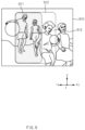
Fig. 4 is a diagram showing a first state of an electronic device according to an embodiment of the disclosure. -
Fig. 5 is a diagram showing a second state of an electronic device according to an embodiment of the disclosure. -
Fig. 6 is an exploded perspective view of an electronic device according to an embodiment of the disclosure. -
Fig. 7 is a block diagram showing an electronic device according to an embodiment of the disclosure. -
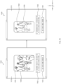
Fig. 8 is a diagram showing an electronic device that displays a preview image according to an embodiment of the disclosure. -
Fig. 9 is a view showing a first area of an image included in a first preview image and a second area of an image included in a second preview image according to an embodiment of the disclosure. -
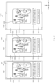
Fig. 10 is a diagram showing an electronic device that displays a preview image according to an embodiment of the disclosure. -
Fig. 11 is a view showing a first area of an image included in a first preview image and a second area of an image included in a second preview image an embodiment of the disclosure. -
Fig. 12 is a view showing a preview image according to a state of the electronic device according to an embodiment of the disclosure. -
Fig. 13 is a view showing a preview image according to a state of the electronic device according to an embodiment of the disclosure. -
Fig. 14 is a diagram showing a background screen setting screen in an electronic device according to an embodiment of the disclosure. -
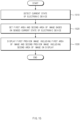
Fig. 15 is a flowchart showing an operation configuration of an electronic device according to an embodiment of the disclosure. -
Fig. 16 is a flowchart showing an operation configuration of an electronic device according to an embodiment of the disclosure. -
Fig. 17 is a diagram showing that an electronic device executes a background screen setting application according to an embodiment of the disclosure. -
Fig. 18 is a diagram showing that an electronic device executes a background screen setting application according to an embodiment of the disclosure. - Throughout the drawings, it should be noted that same or similar reference numbers are used to depict the same or similar elements, features, and structures.
- The following description with reference to the accompanying drawings is provided to assist in a comprehensive understanding of various embodiments of the disclosure as defined by the claims and their equivalents. It includes various specific details to assist in that understanding but these are to be regarded as merely exemplary. Accordingly, those of ordinary skill in the art will recognize that various changes and modifications of the various embodiments described herein can be made without departing from the scope and spirit of the disclosure. In addition, descriptions of well-known functions and constructions may be omitted for clarity and conciseness.
- The terms and words used in the following description and claims are not limited to the bibliographical meanings, but, are merely used by the inventor to enable a clear and consistent understanding of the disclosure. Accordingly, it should be apparent to those skilled in the art that the following description of various embodiments of the disclosure is provided for illustration purpose only and not for the purpose of limiting the disclosure as defined by the appended claims and their equivalents.
- It is to be understood that the singular forms "a," "an," and "the" include plural referents unless the context clearly dictates otherwise. Thus, for example, reference to "a component surface" includes reference to one or more of such surfaces.
-
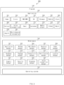
Fig. 1 is a block diagram illustrating an electronic device in a network environment according to various embodiments. Referring toFig. 1 , anelectronic device 101 in anetwork environment 100 may communicate with anelectronic device 102 via a first network 198 (e.g., a short-range wireless communication network), or at least one of anelectronic device 104 or aserver 108 via a second network 199 (e.g., a long-range wireless communication network). According to an embodiment, theelectronic device 101 may communicate with theelectronic device 104 via theserver 108. According to an embodiment, theelectronic device 101 may include aprocessor 120,memory 130, aninput module 150, asound output module 155, adisplay module 160, anaudio module 170, asensor module 176, aninterface 177, aconnecting terminal 178, ahaptic module 179, acamera module 180, apower management module 188, abattery 189, acommunication module 190, a subscriber identification module(SIM) 196, or anantenna module 197. In some embodiments, at least one of the components (e.g., the connecting terminal 178) may be omitted from theelectronic device 101, or one or more other components may be added in theelectronic device 101. In some embodiments, some of the components (e.g., thesensor module 176, thecamera module 180, or the antenna module 197) may be implemented as a single component (e.g., the display module 160). - The
processor 120 may execute, for example, software (e.g., a program 140) to control at least one other component (e.g., a hardware or software component) of theelectronic device 101 coupled with theprocessor 120, and may perform various data processing or computation. According to one embodiment, as at least part of the data processing or computation, theprocessor 120 may store a command or data received from another component (e.g., thesensor module 176 or the communication module 190) involatile memory 132, process the command or the data stored in thevolatile memory 132, and store resulting data innon-volatile memory 134. According to an embodiment, theprocessor 120 may include a main processor 121 (e.g., a central processing unit (CPU) or an application processor (AP)), or an auxiliary processor 123 (e.g., a graphics processing unit (GPU), a neural processing unit (NPU), an image signal processor (ISP), a sensor hub processor, or a communication processor (CP)) that is operable independently from, or in conjunction with, themain processor 121. For example, when theelectronic device 101 includes themain processor 121 and theauxiliary processor 123, theauxiliary processor 123 may be adapted to consume less power than themain processor 121, or to be specific to a specified function. Theauxiliary processor 123 may be implemented as separate from, or as part of themain processor 121. - The
auxiliary processor 123 may control at least some of functions or states related to at least one component (e.g., thedisplay module 160, thesensor module 176, or the communication module 190) among the components of theelectronic device 101, instead of themain processor 121 while themain processor 121 is in an inactive (e.g., sleep) state, or together with themain processor 121 while themain processor 121 is in an active state (e.g., executing an application). According to an embodiment, the auxiliary processor 123 (e.g., an image signal processor or a communication processor) may be implemented as part of another component (e.g., thecamera module 180 or the communication module 190) functionally related to theauxiliary processor 123. According to an embodiment, the auxiliary processor 123 (e.g., the neural processing unit) may include a hardware structure specified for artificial intelligence model processing. An artificial intelligence model may be generated by machine learning. Such learning may be performed, e.g., by theelectronic device 101 where the artificial intelligence is performed or via a separate server (e.g., the server 108). Learning algorithms may include, but are not limited to, e.g., supervised learning, unsupervised learning, semi-supervised learning, or reinforcement learning. The artificial intelligence model may include a plurality of artificial neural network layers. The artificial neural network may be a deep neural network (DNN), a convolutional neural network (CNN), a recurrent neural network (RNN), a restricted boltzmann machine (RBM), a deep belief network (DBN), a bidirectional recurrent deep neural network (BRDNN), deep Q-network or a combination of two or more thereof but is not limited thereto. The artificial intelligence model may, additionally or alternatively, include a software structure other than the hardware structure. - The
memory 130 may store various data used by at least one component (e.g., theprocessor 120 or the sensor module 176) of theelectronic device 101. The various data may include, for example, software (e.g., the program 140) and input data or output data for a command related thererto. Thememory 130 may include thevolatile memory 132 or thenon-volatile memory 134. - The
program 140 may be stored in thememory 130 as software, and may include, for example, an operating system (OS) 142,middleware 144, or anapplication 146. - The
input module 150 may receive a command or data to be used by another component (e.g., the processor 120) of theelectronic device 101, from the outside (e.g., a user) of theelectronic device 101. Theinput module 150 may include, for example, a microphone, a mouse, a keyboard, a key (e.g., a button), or a digital pen (e.g., a stylus pen). - The
sound output module 155 may output sound signals to the outside of theelectronic device 101. Thesound output module 155 may include, for example, a speaker or a receiver. The speaker may be used for general purposes, such as playing multimedia or playing record. The receiver may be used for receiving incoming calls. According to an embodiment, the receiver may be implemented as separate from, or as part of the speaker. - The
display module 160 may visually provide information to the outside (e.g., a user) of theelectronic device 101. Thedisplay module 160 may include, for example, a display, a hologram device, or a projector and control circuitry to control a corresponding one of the display, hologram device, and projector. According to an embodiment, thedisplay module 160 may include a touch sensor adapted to detect a touch, or a pressure sensor adapted to measure the intensity of force incurred by the touch. - The
audio module 170 may convert a sound into an electrical signal and vice versa. According to an embodiment, theaudio module 170 may obtain the sound via theinput module 150, or output the sound via thesound output module 155 or a headphone of an external electronic device (e.g., an electronic device 102) directly (e.g., wiredly) or wirelessly coupled with theelectronic device 101. - The
sensor module 176 may detect an operational state (e.g., power or temperature) of theelectronic device 101 or an environmental state (e.g., a state of a user) external to theelectronic device 101, and then generate an electrical signal or data value corresponding to the detected state. According to an embodiment, thesensor module 176 may include, for example, a gesture sensor, a gyro sensor, an atmospheric pressure sensor, a magnetic sensor, an acceleration sensor, a grip sensor, a proximity sensor, a color sensor, an infrared (IR) sensor, a biometric sensor, a temperature sensor, a humidity sensor, or an illuminance sensor. - The
interface 177 may support one or more specified protocols to be used for theelectronic device 101 to be coupled with the external electronic device (e.g., the electronic device 102) directly (e.g., wiredly) or wirelessly. According to an embodiment, theinterface 177 may include, for example, a high definition multimedia interface (HDMI), a universal serial bus (USB) interface, a secure digital (SD) card interface, or an audio interface. - A connecting
terminal 178 may include a connector via which theelectronic device 101 may be physically connected with the external electronic device (e.g., the electronic device 102). According to an embodiment, the connectingterminal 178 may include, for example, a HDMI connector, a USB connector, a SD card connector, or an audio connector (e.g., a headphone connector). - The
haptic module 179 may convert an electrical signal into a mechanical stimulus (e.g., a vibration or a movement) or electrical stimulus which may be recognized by a user via his tactile sensation or kinesthetic sensation. According to an embodiment, thehaptic module 179 may include, for example, a motor, a piezoelectric element, or an electric stimulator. - The
camera module 180 may capture a still image or moving images. According to an embodiment, thecamera module 180 may include one or more lenses, image sensors, image signal processors, or flashes. - The
power management module 188 may manage power supplied to theelectronic device 101. According to one embodiment, thepower management module 188 may be implemented as at least part of, for example, a power management integrated circuit (PMIC). - The
battery 189 may supply power to at least one component of theelectronic device 101. According to an embodiment, thebattery 189 may include, for example, a primary cell which is not rechargeable, a secondary cell which is rechargeable, or a fuel cell. - The
communication module 190 may support establishing a direct (e.g., wired) communication channel or a wireless communication channel between theelectronic device 101 and the external electronic device (e.g., theelectronic device 102, theelectronic device 104, or the server 108) and performing communication via the established communication channel. Thecommunication module 190 may include one or more communication processors that are operable independently from the processor 120 (e.g., the application processor (AP)) and supports a direct (e.g., wired) communication or a wireless communication. According to an embodiment, thecommunication module 190 may include a wireless communication module 192 (e.g., a cellular communication module, a short-range wireless communication module, or a global navigation satellite system (GNSS) communication module) or a wired communication module 194 (e.g., a local area network (LAN) communication module or a power line communication (PLC) module). A corresponding one of these communication modules may communicate with the external electronic device via the first network 198 (e.g., a short-range communication network, such as Bluetooth™, wireless-fidelity (Wi-Fi) direct, or infrared data association (IrDA)) or the second network 199 (e.g., a long-range communication network, such as a legacy cellular network, a 5G network, a next-generation communication network, the Internet, or a computer network (e.g., LAN or wide area network (WAN)). These various types of communication modules may be implemented as a single component (e.g., a single chip), or may be implemented as multi components (e.g., multi chips) separate from each other. Thewireless communication module 192 may identify and authenticate theelectronic device 101 in a communication network, such as thefirst network 198 or thesecond network 199, using subscriber information (e.g., international mobile subscriber identity (IMSI)) stored in thesubscriber identification module 196. - The
wireless communication module 192 may support a 5G network, after a 4G network, and next-generation communication technology, e.g., new radio (NR) access technology. The NR access technology may support enhanced mobile broadband (eMBB), massive machine type communications (mMTC), or ultra-reliable and low-latency communications (URLLC). Thewireless communication module 192 may support a high-frequency band (e.g., the millimeter(mm)Wave band) to achieve, e.g., a high data transmission rate. Thewireless communication module 192 may support various technologies for securing performance on a high-frequency band, such as, e.g., beamforming, massive multiple-input and multiple-output (massive MIMO), full dimensional MIMO (FD-MIMO), array antenna, analog beam-forming, or large scale antenna. Thewireless communication module 192 may support various requirements specified in theelectronic device 101, an external electronic device (e.g., the electronic device 104), or a network system (e.g., the second network 199). According to an embodiment, thewireless communication module 192 may support a peak data rate (e.g., 20Gbps or more) for implementing eMBB, loss coverage (e.g., 164dB or less) for implementing mMTC, or U-plane latency (e.g., 0.5ms or less for each of downlink (DL) and uplink (UL), or a round trip of 1ms or less) for implementing URLLC. - The
antenna module 197 may transmit or receive a signal or power to or from the outside (e.g., the external electronic device) of theelectronic device 101. According to an embodiment, theantenna module 197 may include an antenna including a radiating element composed of a conductive material or a conductive pattern formed in or on a substrate (e.g., a printed circuit board (PCB)). According to an embodiment, theantenna module 197 may include a plurality of antennas (e.g., array antennas). In such a case, at least one antenna appropriate for a communication scheme used in the communication network, such as thefirst network 198 or thesecond network 199, may be selected, for example, by the communication module 190 (e.g., the wireless communication module 192) from the plurality of antennas. The signal or the power may then be transmitted or received between thecommunication module 190 and the external electronic device via the selected at least one antenna. According to an embodiment, another component (e.g., a radio frequency integrated circuit (RFIC)) other than the radiating element may be additionally formed as part of theantenna module 197. - According to various embodiments, the
antenna module 197 may form a mmWave antenna module. According to an embodiment, the mmWave antenna module may include a printed circuit board, a RFIC disposed on a first surface (e.g., the bottom surface) of the printed circuit board, or adjacent to the first surface and capable of supporting a designated high-frequency band (e.g., the mmWave band), and a plurality of antennas (e.g., array antennas) disposed on a second surface (e.g., the top or a side surface) of the printed circuit board, or adjacent to the second surface and capable of transmitting or receiving signals of the designated high-frequency band. - At least some of the above-described components may be coupled mutually and communicate signals (e.g., commands or data) therebetween via an inter-peripheral communication scheme (e.g., a bus, general purpose input and output (GPIO), serial peripheral interface (SPI), or mobile industry processor interface (MIPI)).
- According to an embodiment, commands or data may be transmitted or received between the
electronic device 101 and the externalelectronic device 104 via theserver 108 coupled with thesecond network 199. Each of theelectronic devices electronic device 101. According to an embodiment, all or some of operations to be executed at theelectronic device 101 may be executed at one or more of the externalelectronic devices electronic device 101 should perform a function or a service automatically, or in response to a request from a user or another device, theelectronic device 101, instead of, or in addition to, executing the function or the service, may request the one or more external electronic devices to perform at least part of the function or the service. The one or more external electronic devices receiving the request may perform the at least part of the function or the service requested, or an additional function or an additional service related to the request, and transfer an outcome of the performing to theelectronic device 101. Theelectronic device 101 may provide the outcome, with or without further processing of the outcome, as at least part of a reply to the request. To that end, a cloud computing, distributed computing, mobile edge computing (MEC), or client-server computing technology may be used, for example. Theelectronic device 101 may provide ultra low-latency services using, e.g., distributed computing or mobile edge computing. In another embodiment, the externalelectronic device 104 may include an internet-of-things (IoT) device. Theserver 108 may be an intelligent server using machine learning and/or a neural network. According to an embodiment, the externalelectronic device 104 or theserver 108 may be included in thesecond network 199. Theelectronic device 101 may be applied to intelligent services (e.g., smart home, smart city, smart car, or healthcare) based on 5G communication technology or loT-related technology. -
Fig. 2 is a block diagram illustrating a display module according to an embodiment of the disclosure. Referring toFig. 2 , in a block diagram 200, thedisplay module 160 may include adisplay 210 and a display driver integrated circuit (DDI) 230 to control thedisplay 210. TheDDI 230 may include aninterface module 231, memory 233 (e.g., buffer memory), animage processing module 235, or amapping module 237. TheDDI 230 may receive image information that contains image data or an image control signal corresponding to a command to control the image data from another component of theelectronic device 101 via theinterface module 231. For example, according to an embodiment, the image information may be received from the processor 120 (e.g., the main processor 121 (e.g., an application processor)) or the auxiliary processor 123 (e.g., a graphics processing unit) operated independently from the function of themain processor 121. TheDDI 230 may communicate, for example, withtouch circuitry 150 or thesensor module 176 via theinterface module 231. TheDDI 230 may also store at least part of the received image information in thememory 233, for example, on a frame by frame basis. Theimage processing module 235 may perform pre-processing or post-processing (e.g., adjustment of resolution, brightness, or size) with respect to at least part of the image data. According to an embodiment, the pre-processing or post-processing may be performed, for example, based at least in part on one or more characteristics of the image data or one or more characteristics of thedisplay 210. Themapping module 237 may generate a voltage value or a current value corresponding to the image data pre-processed or post-processed by theimage processing module 235. According to an embodiment, the generating of the voltage value or current value may be performed, for example, based at least in part on one or more attributes of the pixels (e.g., an array, such as an RGB stripe or a pentile structure, of the pixels, or the size of each subpixel). At least some pixels of thedisplay 210 may be driven, for example, based at least in part on the voltage value or the current value such that visual information (e.g., a text, an image, or an icon) corresponding to the image data may be displayed via thedisplay 210. - According to an embodiment, the
display module 160 may further include thetouch circuitry 250. Thetouch circuitry 250 may include atouch sensor 251 and atouch sensor IC 253 to control thetouch sensor 251. Thetouch sensor IC 253 may control thetouch sensor 251 to sense a touch input or a hovering input with respect to a certain position on thedisplay 210. To achieve this, for example, thetouch sensor 251 may detect (e.g., measure) a change in a signal (e.g., a voltage, a quantity of light, a resistance, or a quantity of one or more electric charges) corresponding to the certain position on thedisplay 210. Thetouch circuitry 250 may provide input information (e.g., a position, an area, a pressure, or a time) indicative of the touch input or the hovering input detected via thetouch sensor 251 to theprocessor 120. According to an embodiment, at least part (e.g., the touch sensor IC 253) of thetouch circuitry 250 may be formed as part of thedisplay 210 or theDDI 230, or as part of another component (e.g., the auxiliary processor 123) disposed outside thedisplay module 160. - According to an embodiment, the
display module 160 may further include at least one sensor (e.g., a fingerprint sensor, an iris sensor, a pressure sensor, or an illuminance sensor) of thesensor module 176 or a control circuit for the at least one sensor. In such a case, the at least one sensor or the control circuit for the at least one sensor may be embedded in one portion of a component (e.g., thedisplay 210, theDDI 230, or the touch circuitry 250)) of thedisplay module 160. For example, when thesensor module 176 embedded in thedisplay module 160 includes a biometric sensor (e.g., a fingerprint sensor), the biometric sensor may obtain biometric information (e.g., a fingerprint image) corresponding to a touch input received via a portion of thedisplay 210. As another example, when thesensor module 176 embedded in thedisplay module 160 includes a pressure sensor, the pressure sensor may obtain pressure information corresponding to a touch input received via a partial or whole area of thedisplay 210. According to an embodiment, thetouch sensor 251 or thesensor module 176 may be disposed between pixels in a pixel layer of thedisplay 210, or over or under the pixel layer. -
Fig. 3 is a block diagram illustrating the program according to an embodiment of the disclosure. Referring toFig. 3 , according to an embodiment, theprogram 140 may include an operating system (OS) 142 to control one or more resources of theelectronic device 101,middleware 144, or anapplication 146 executable in theOS 142. TheOS 142 may include, for example, Android™, iOS™, Windows™, Symbian™, Tizen™, or Bada™. At least part of theprogram 140, for example, may be pre-loaded on theelectronic device 101 during manufacture, or may be downloaded from or updated by an external electronic device (e.g., theelectronic device - The
OS 142 may control management (e.g., allocating or deallocation) of one or more system resources (e.g., process, memory, or power source) of theelectronic device 101. TheOS 142, additionally or alternatively, may include one or more driver programs to drive other hardware devices of theelectronic device 101, for example, theinput module 150, thesound output module 155, thedisplay module 160, theaudio module 170, thesensor module 176, theinterface 177, thehaptic module 179, thecamera module 180, thepower management module 188, thebattery 189, thecommunication module 190, thesubscriber identification module 196, or theantenna module 197. - The
middleware 144 may provide various functions to theapplication 146 such that a function or information provided from one or more resources of theelectronic device 101 may be used by theapplication 146. Themiddleware 144 may include, for example, anapplication manager 301, awindow manager 303, amultimedia manager 305, aresource manager 307, apower manager 309, adatabase manager 311, apackage manager 313, a connectivity manager 315, anotification manager 317, alocation manager 319, agraphic manager 321, asecurity manager 323, atelephony manager 325, or avoice recognition manager 327. - The
application manager 301, for example, may manage the life cycle of theapplication 146. Thewindow manager 303, for example, may manage one or more graphical user interface (GUI) resources that are used on a screen. Themultimedia manager 305, for example, may identify one or more formats to be used to play media files, and may encode or decode a corresponding one of the media files using a codec appropriate for a corresponding format selected from the one or more formats. Theresource manager 307, for example, may manage the source code of theapplication 146 or a memory space of the memory 130.Thepower manager 309, for example, may manage the capacity, temperature, or power of thebattery 189, and determine or provide related information to be used for the operation of theelectronic device 101 based at least in part on corresponding information of the capacity, temperature, or power of thebattery 189. According to an embodiment, thepower manager 309 may interwork with a basic input/output system (BIOS) (not shown) of theelectronic device 101. - The
database manager 311, for example, may generate, search, or change a database to be used by theapplication 146. Thepackage manager 313, for example, may manage installation or update of an application that is distributed in the form of a package file. The connectivity manager 315, for example, may manage a wireless connection or a direct connection between theelectronic device 101 and the external electronic device. Thenotification manager 317, for example, may provide a function to notify a user of an occurrence of a specified event (e.g., an incoming call, message, or alert). Thelocation manager 319, for example, may manage locational information on theelectronic device 101. Thegraphic manager 321, for example, may manage one or more graphic effects to be offered to a user or a user interface related to the one or more graphic effects. - The
security manager 323, for example, may provide system security or user authentication. Thetelephony manager 325, for example, may manage a voice call function or a video call function provided by theelectronic device 101. Thevoice recognition manager 327, for example, may transmit a user's voice data to theserver 108, and receive, from theserver 108, a command corresponding to a function to be executed on theelectronic device 101 based at least in part on the voice data, or text data converted based at least in part on the voice data. According to an embodiment, themiddleware 144 may dynamically delete some existing components or add new components. According to an embodiment, at least part of themiddleware 144 may be included as part of theOS 142 or may be implemented as another software separate from theOS 142. - The
application 146 may include, for example, ahome 351,dialer 353, short message service (SMS)/multimedia messaging service (MMS) 355, instant message (IM) 357,browser 359,camera 361,alarm 363, contact 365,voice recognition 367,email 369,calendar 371,media player 373,album 375, watch 377, health 379 (e.g., for measuring the degree of workout or biometric information, such as blood sugar), or environmental information 381 (e.g., for measuring air pressure, humidity, or temperature information) application. According to an embodiment, theapplication 146 may further include an information exchanging application (not shown) that is capable of supporting information exchange between theelectronic device 101 and the external electronic device. The information exchange application, for example, may include a notification relay application adapted to transfer designated information (e.g., a call, message, or alert) to the external electronic device or a device management application adapted to manage the external electronic device. The notification relay application may transfer notification information corresponding to an occurrence of a specified event (e.g., receipt of an email) at another application (e.g., the email application 369) of theelectronic device 101 to the external electronic device. Additionally or alternatively, the notification relay application may receive notification information from the external electronic device and provide the notification information to a user of theelectronic device 101. - The device management application may control the power (e.g., turn-on or turn-off) or the function (e.g., adjustment of brightness, resolution, or focus) of the external electronic device or some component thereof (e.g., a display device or a camera module of the external electronic device). The device management application, additionally or alternatively, may support installation, delete, or update of an application running on the external electronic device.
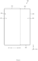
Fig. 4 is a diagram showing a first state of an electronic device according to an embodiment of the disclosure.Fig. 5 is a diagram showing a second state of an electronic device according to an embodiment of the disclosure. - Referring to
Figs. 4 andFig. 5 , an electronic device 400 (e.g., theelectronic device 101 inFig. 1 ) according to one embodiment may include a housing and adisplay 450. The housing may include afirst structure 410 and asecond structure 440. - In one embodiment, the
electronic device 400 may be of a slidable type or a rollable type. Theelectronic device 400 may include the first state (e.g., a closed state or a retracted state) and the second state (e.g., an opened state or an extended state). The first state and the second state may be determined based on a relative position of thesecond structure 440 with respect to thefirst structure 410. Theelectronic device 400 may be deformable into between the first state and the second state via a user's manipulation or a mechanical operation. - In one embodiment, the first state may refer to a state in which an area (or a size) of the
display 450 visually exposed in a frontward direction of theelectronic device 400 is relatively reduced. The second state may refer to a state in which the area (or the size) of thedisplay 450 exposed in a frontward direction of theelectronic device 400 is relatively enlarged. For example, the second state may be a state in which the area of thedisplay 450 visually exposed in a frontward direction of theelectronic device 400 is larger than that in the first state. Further, in the first state, a portion (e.g.,side portions second structure 440 may be located inwardly (or outwardly) of thefirst structure 410, such that thesecond structure 440 may be in a closed state with respect to thefirst structure 410. In the second state, theportions second structure 440 exit from thefirst structure 410 sch that thesecond structure 440 may be in an opened state with respect to thefirst structure 410. In one embodiment, theelectronic device 400 may further include a third state (hereinafter, also referred to as an intermediate state) between the first state and the second state. For example, the intermediate state may have a larger area of thedisplay 450 that is visually exposed in a frontward direction of theelectronic device 400 compared to that in the first state, and a smaller area of thedisplay 450 that is visually exposed in a frontward direction of theelectronic device 400 compared to that in the second state. - In one embodiment, the
first structure 410 and thesecond structure 440 may be coupled to each other such that thefirst structure 410 and thesecond structure 440 slides relative to each other. Thesecond structure 440 may be slidably coupled to one side of thefirst structure 410. For example, thefirst structure 410 may be a fixed structure, and thesecond structure 440 may be a structure that is relatively movable with respect to thefirst structure 410. Thesecond structure 440 may be coupled to one side of thefirst structure 410 so as to be slidable in both directions (e.g., +x/-x axis directions) with respect to thefirst structure 410. - In another embodiment, a long side surface (e.g., a surface extending in the y-axis direction) of the
second structure 440 may slide in both directions (e.g., the +y/-y-axis directions). In still another embodiment, theelectronic device 400 includes a plurality ofsecond structures 440. One second structure may slide in one direction (e.g., +x-axis direction or +y-axis direction), and the other second structure may slide in the opposite direction (e.g., -x-axis direction or -y-axis direction). - In one embodiment, the
electronic device 400 may be deformed into the first state and the second state as thesecond structure 440 slides with respect to thefirst structure 410. For example, in theelectronic device 400, thesecond structure 440 may move in a second direction DR2 with respect to thefirst structure 410 in the first state (e.g., the state ofFig. 4 ) such that theelectronic device 400 may be deformed into the second state (e.g., the state ofFig. 5 ). Conversely, thesecond structure 440 may move in a first direction DR1 with respect to thefirst structure 410 in the second state such that theelectronic device 400 may be deformed into the first state. - In one embodiment, the
display 450 may change the size (or the area) of the area thereof exposed in a frontward direction of theelectronic device 400 in response to the sliding operation of thesecond structure 440. While thedisplay 450 is supported on at least one of thefirst structure 410 or thesecond structure 440, a size of the exposed area thereof may increase or decrease according to the sliding operation of thesecond structure 440. Thedisplay 450 may include at least a partially flexible part. - In one embodiment, the
display 450 may include a basic area AA1 and an extended area AA2 extending from the basic area AA1. The basic area AA1 may be maintained at a state exposed in a frontward direction of theelectronic device 400. The extended area AA2 may have a variable size of an area exposed in a frontward direction of theelectronic device 400 according to the state of theelectronic device 400. The extended area AA2 may extend from one side of the basic area AA1. For example, the basic area AA1 may mean a partial area of thedisplay 450 visually exposed in a frontward direction of theelectronic device 400 in the first state. The extended area AA2 may be refer to an area which is located inside theelectronic device 400 in the first state, and whose at least a portion extends out of theelectronic device 400 and is visually exposed in a frontward direction of theelectronic device 400 in the second state. - In one embodiment, in the first state, the basic area AA1 may be located across a front surface of the
electronic device 400, and the extended area AA2 may be located inside thefirst structure 410. The second state may refer to a state in which at least a portion of the extended area AA2 together with the basic area AA1 are located across the front surface of theelectronic device 400. In theelectronic device 400, the extended area AA2 is additionally exposed in a frontward direction of theelectronic device 400 in the second state, so that a size of the exposed area of thedisplay 450 may increase. Thedisplay 450 may include a display area which is visually exposed in a frontward direction of theelectronic device 400 and in which predetermined visual information (or screen) is displayed. For example, in the first state, the display area may correspond to the basic area AA1. In the second state, the display area may correspond to a sum of a portion of the extended area AA2 and the basic area AA1. In the second state, theelectronic device 400 may provide an extended display area larger than that in the first state as the screen may be displayed on the portion of the extended area AA2 together with the basic area AA1 in the second state. - In one embodiment, the
electronic device 400 may be manually switched to the first state and/or the second state by the user or a driving mechanism (e.g., a drive motor, a reduction gear module and/or a gear assembly) disposed inside thefirst structure 410 or thesecond structure 440. According to one embodiment, an operation of the driving mechanism may be triggered based on user input. According to one embodiment, the user input for triggering the operation of the driving mechanism may include a touch input, a force touch input, and/or a gesture input on thedisplay 450. In another embodiment, the user input for triggering the operation of the driving mechanism may include a voice input, or an input to a physical button disposed on an outer face of thefirst structure 410 and/or thesecond structure 440 and exposed outwardly. -
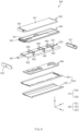
Fig. 6 is an exploded perspective view of an electronic device according to an embodiment of the disclosure. Referring toFig. 6 , anelectronic device 600 according to one embodiment may include a housing including afirst structure 610 and asecond structure 640, adisplay 650, afirst roller 691, asecond roller 692, atension belt 693, and acircuit board 694. - In one embodiment, the
first structure 610 may include acasing 620 and abracket 630. Thebracket 630 may be coupled to thecasing 620, and at least a portion thereof may be surrounded with thecasing 620. For example, thebracket 630 may be fixed to thecasing 620. Thecasing 620 and thebracket 630 may be movable relative to thesecond structure 640 in response to a sliding operation of thesecond structure 640. Thecasing 620 and thebracket 630 may act as a reference for sliding movement of thesecond structure 640 and thedisplay 650. - In one embodiment, the
casing 620 may define at least a portion of an outer surface of theelectronic device 600. Thecasing 620 may include afirst side member 621, asecond side member 622, and arear member 623. Thefirst side member 621 and thesecond side member 622 may face toward each other in a direction substantially perpendicular to a sliding direction (e.g., the first direction DR1 and the second direction DR2) of thesecond structure 640. Therear member 623 may be disposed between thefirst side member 621 and thesecond side member 622, and may be connected to each of thefirst side member 621 and thesecond side member 622. Thefirst side member 621, thesecond side member 622, and therear member 623 may be coupled to each other to define a space in which at least some of other components (e.g., thebracket 630, thesecond structure 640, and the circuit board 694) of theelectronic device 600 may be disposed. - In one embodiment, the
rear member 623 may include aframe 624 and acover 625. For example, theframe 624 may be coupled to thebracket 630. Thecover 625 may be coupled to theframe 624 to form at least a portion of the rear surface of theelectronic device 600. A space in which thesecond structure 640 and the extended area AA2 of thedisplay 650 are accommodated may be located between thecover 625 and thebracket 630. - According to the illustrated embodiment, the
first side member 621, thesecond side member 622, theframe 624 and/or therear cover 625 may be formed as separate components, and may be assembled with each other or may be combined with each other. However, the disclosure is not limited thereto. According to various embodiments of the disclosure, thefirst side member 621, thesecond side member 622, theframe 624 and therear cover 625 are integrally formed with each other to constitute one part. - In one embodiment, the
bracket 630 may be disposed to at least partially overlap thesecond structure 640. A first surface 631 (e.g., a surface facing in the +z-axis direction or a top surface based onFig. 6 ) of thebracket 630 may face toward theplate portion 641 of thesecond structure 640. A second surface 632 (e.g., a surface facing in the -z-axis direction or a bottom surface based onFig. 6 ) of thebracket 630 may face toward thecircuit board 694. Thecircuit board 694 may be disposed on thesecond surface 632 of thebracket 630. - In one embodiment, the
second structure 640 may be disposed to surround at least a portion of thebracket 630. Thesecond structure 640 may include theplate portion 641 supporting a portion of the basic area AA1 of thedisplay 650 and amulti-joint member 642 that supports another portion of the basic area AA1 and a portion of the extended area AA2 of the flexible display (i.e., display 650). For example, themulti-joint member 642 may extend from theplate portion 641, and may be bendable. Themulti-joint member 642 may be at least partially curved in response to the sliding operation of thesecond structure 640. - In one embodiment, the
multi-joint member 642 may be coupled to thefirst roller 691. Themulti-joint member 642 may include a plurality of bars extending in a direction substantially parallel to a rolling axis R of thefirst roller 691. For example, themulti-joint member 642 may include a flexible track or a hinge rail. According to one embodiment, theplate portion 641 may be configured to slide in the first direction DR1 or the second direction DR2. Themulti-joint member 642 may be configured such that a portion thereof rotates via thefirst roller 691 and the other portion thereof slides in the first direction DR1 or the second direction DR2. - In one embodiment, the
first roller 691 may be disposed on one side surface of thebracket 630. Thefirst roller 691 may be rotatably coupled to thebracket 630. For example, thefirst roller 691 may rotate in both directions about the rolling axis R according to the sliding operation of thesecond structure 640. Thefirst roller 691 may contact a portion of themulti-joint member 642 of thesecond structure 640. For example, thesecond structure 640 may be disposed such that themulti-joint member 642 surrounds at least a portion of thefirst roller 691. Thefirst roller 691 may be configured to rotate a portion of themulti-joint member 642. Thefirst roller 691 may contact an area of themulti-joint member 642 varying according to the state change of theelectronic device 600. - In one embodiment, the
second structure 640 may be slidably coupled to thebracket 630 via thetension belt 693 and thesecond roller 692. Thetension belt 693 may connect an end of theplate portion 641 of thesecond structure 640 and an end of themulti-joint member 642 to each other. Thesecond roller 692 may be configured to rotate in the same direction as a rotation direction of thefirst roller 691 according to the sliding operation of thesecond structure 640. For example, thetension belt 693 may be configured to provide tension to themulti-joint member 642 while being disposed between theplate portion 641 and themulti-joint member 642. According to one embodiment, when theplate portion 641 moves in the first direction DR1, one end of thetension belt 693 connected to theplate portion 641 may move in the first direction DR1, while the opposite end of thetension belt 693 connected to themulti-joint member 642 may move in the second direction DR2. Conversely, when theplate portion 641 moves in the second direction DR2, one end of thetension belt 693 may move in the second direction DR2, while the opposite end of thetension belt 693 may move in the first direction DR1. However, the illustrated embodiment is illustrative. According to various embodiments, theelectronic device 600 may not include at least one of thesecond roller 692 or thetension belt 693. - In one embodiment, the
display 650 may be disposed on thesecond structure 640. For example, thedisplay 650 may be coupled to thesecond structure 640 such that thedisplay 650 together with thesecond structure 640 perform sliding movement with respect to thefirst structure 610. Thedisplay 650 may include the basic area AA1 and the extended area AA2 extending from the basic area AA1. For example, the basic area AA1 may mean an area visually exposed in a frontward direction of theelectronic device 600 in the first state. The extended area AA2 may refer to an area which may be located inside theelectronic device 600 in the first state, and whose at least a portion moves out of theelectronic device 600 and thus is visually exposed in a frontward direction of theelectronic device 600 in the second state. - The
electronic device 600 according to an embodiment may be configured such that in the first state, the basic area AA1 may be visually exposed in a frontward direction of theelectronic device 600, and in the second state, at least a portion of the extended area AA2 together with the basic area AA1 may be visually exposed in a frontward direction of theelectronic device 600. A position of the extended area AA2 may vary as at least a portion thereof rotates together with the rotation of thefirst roller 691. For example, as thesecond structure 640 moves in the first direction DR1 with respect to thefirst structure 610, the extended area AA2 together with the basic area AA1 may be disposed on the front surface of theelectronic device 600. Further, the extended area AA2 may be accommodated in a space between thebracket 630 and therear member 623 as thesecond structure 640 moves in the second direction DR2 with respect to thefirst structure 610. - In one embodiment, the
circuit board 694 may be disposed in thefirst structure 610. Thecircuit board 694 may be disposed between thebracket 630 and therear member 623. For example, thecircuit board 694 may be disposed inside theelectronic device 600 while being supported on thebracket 630. Thecircuit board 694 may be coupled to at least a partial area of thesecond surface 632 of thebracket 630 and thus may be fixed to thefirst structure 610. Thecircuit board 694 together with thefirst structure 610 may move relative to thesecond structure 640 during the sliding operation of thesecond structure 640. - In one embodiment, the
circuit board 694 may include a printed circuit board (PCB), a flexible PCB (FPCB), or a rigid-flexible PCB (RFPCB). Various electronic components included in theelectronic device 600 may be electrically connected to thecircuit board 694. A processor (e.g., theprocessor 120 inFig. 1 ), a memory (e.g., thememory 130 inFig. 1 ) and/or an interface (e.g., theinterface 177 inFig. 1 ) may be disposed in the circuit board 694 ). For example, the processor may include a main the processor and/or an auxiliary processor. The main the processor and/or the auxiliary processor may include one or more of a central processing unit, an application the processor, a graphics processing unit, and an image signal processor, a sensor hub processor or a communication processor. For example, the memory may include a volatile memory or a non-volatile memory. For example, the interface may include a high definition multimedia interface (HDMI), a universal serial bus (USB) interface, an SD card interface, and/or an audio interface. Further, the interface may electrically or physically connect theelectronic device 600 to an external electronic device, and may include a USB connector, an SD card/MMC connector, or an audio connector. - In one embodiment, a battery (e.g., the
battery 189 inFig. 1 ) may supply power to at least one component of theelectronic device 600. The battery may be integrally disposed inside theelectronic device 600 or may be disposed detachably from theelectronic device 600. According to various embodiments of the disclosure, the battery may be disposed inside theelectronic device 600 while the battery together with thecircuit board 694 are supported on thebracket 630. The battery may be coupled to at least a partial area of thesecond surface 632 of thebracket 630. The battery may be substantially coplanar with thecircuit board 694. The battery together with thefirst structure 610 may move relative to thesecond structure 640 during the sliding operation of thesecond structure 640. -
Fig. 7 is a block diagram showing an electronic device according to an embodiment of the disclosure. Referring toFig. 7 , anelectronic device 700 according to one embodiment (e.g., theelectronic device 101 inFig. 1 ) may include a display 710 (e.g., thedisplay module 160 inFig. 1 ), a memory 730 (e.g., thememory 130 inFig. 1 ) and a processor 720 (e.g., theprocessor 120 inFig. 1 ). - At least a portion of the
display 710 may include a flexible area. According to one embodiment, thedisplay 710 may be configured to extend and retract. For example, thedisplay 710 may include at least one of a slideable display, a foldable display, or a rollable display. - Depending on the state of the
electronic device 700, a size of the display area (or the exposed area) of thedisplay 710 may increase or decrease. In the first state (e.g., the retracted state) of theelectronic device 700, the display area of thedisplay 710 may retract, and in the second state (e.g., the extended state), the display area of thedisplay 710 may extend. For example, in the first state of theelectronic device 700, at least a portion of thedisplay 710 may be disposed in a rolled or bent state and within theelectronic device 700, and thus may not be visually exposed. In the second state of theelectronic device 700, the at least a portion of thedisplay 710 may be unfolded and thus visually exposed. - According to one embodiment, the
display 710 may extend or retract in an automatic, semi-automatic, or manual manner. For example, thedisplay 710 may further receive a driving motor (not shown) therein. Theautomatic display 710 may automatically extend or retract using the driving motor based on a specified signal created by theprocessor 720. For example, in the semi-automatic manner, thedisplay 710 of theelectronic device 700 may automatically extend based on an operation of the drive motor based on a specified signal created by theprocessor 720. Then, thedisplay 710 of theelectronic device 700 may retract by a user directly applying a force to thedisplay 710 of theelectronic device 700 in the extended state. For example, in the manual manner, thedisplay 710 of theelectronic device 700 may extend or retract by a user directly applying a force to thedisplay 710 of theelectronic device 700. The display as described with reference to the drawings to be described later may extend or retract in the above-described automatic, semi-automatic, or manual manner. In another example, thedisplay 710 may extend based on an input applied to a pre-specified area. When an input provided from the user (e.g., an input based on a physical key, a touch input, a long press input, or an input of a specified pattern (e.g., knocks)) is applied to a predetermined area of thedisplay 710 in the state in which thedisplay 710 has retracted, thedisplay 710 may automatically extend. In various embodiments, thedisplay 710 may extend when an input provided from an external input device (not shown) (e.g., a stylus pen) is applied to a predetermined area in the state in which thedisplay 710 has retracted. - The
memory 730 may store therein at least one program, at least one application, data, or instructions executed by theprocessor 720. According to one embodiment, thememory 730 may include at least a portion of thememory 130 shown inFig. 1 . According to one embodiment, thememory 730 may store therein information or instructions for performing at least a portion of an operation of theelectronic device 700 to be described later. According to one embodiment, thememory 730 may store therein instructions related to a plurality of applications executed by theprocessor 720. - The
processor 720 may detect the state of theelectronic device 700 using a sensor (e.g., thesensor module 176 ofFig. 1 ). For example, the sensor may be at least one of a magnetic sensor such as a hall sensor, a proximity sensor, an illuminance sensor, a touch sensor, a bending sensor, and an infrared sensor, or a combination thereof. For example, theprocessor 720 may identify a rolling state or a sliding state of thedisplay 710. Theprocessor 720 may identify rolling in/out (or sliding in/out) and a rolling amount (or a sliding amount). According to an embodiment, theprocessor 720 may acquire state information about the state of theelectronic device 700 from the sensor. - According to one embodiment, in order to detect the state of the
electronic device 700, theprocessor 720 may include another sensor for checking movement (rotation) of a magnetic body (e.g., in the x-axis, y-axis, and z-axis directions). For example, theelectronic device 700 may include a TMR sensor (a tunnel magneto-resistance sensor) and thus may use a resistance value that changes based on relative angles between a plurality of magnetic units of the TMR sensor to check movement (rotation) of the magnetic body. Further, according to another embodiment, theelectronic device 700 may check the movement (rotation) of the magnetic body using an anisotropic magneto-resistance (AMR) sensor or a giant magneto-resistance (GMR) sensor. - In one embodiment, the sensor may include at least one of an accelerometer, a gyro sensor (e.g., a gyroscope), and a geomagnetic sensor. Alternatively, the sensor may detect an inclination angle of the
electronic device 700 with respect to a ground surface and/or a direction in which theelectronic device 700 faces in a three-dimensional coordinate system, using sensed data acquired from at least one of the accelerometer, the gyro sensor or the geomagnetic sensor. However, the present disclosure is not limited thereto. Various sensors capable of obtaining information about the inclination angle of theelectronic device 700 may be used. For example, the accelerometer may sense information about linear motion of theelectronic device 700 and/or acceleration of theelectronic device 700 in three axes. The gyro sensor may sense information related to the rotation of theelectronic device 700, and the geomagnetic sensor may sense information about a direction in which theelectronic device 700 faces in an absolute coordinate system. - According to one embodiment, the
processor 720 may create a virtual coordinate space based on an azimuth (e.g., a yaw, pitch and/or roll value) as measured by a 9-axis motion sensor (e.g., the accelerometer, the gyro sensor, and the geomagnetic sensor). Theprocessor 720 may define one area of the virtual coordinate space as a landscape range, and another area thereof as a portrait range. According to one embodiment, when a current state of theelectronic device 700 is included in the landscape range, theprocessor 720 may determine that theelectronic device 700 has a landscape orientation. For example, the landscape orientation of theelectronic device 700 may represent a state in which parallel long sides of theelectronic device 700 are parallel to a horizontal axis parallel to the ground. According to one embodiment, when the current state of theelectronic device 700 is included in the portrait range, theprocessor 720 may determine that theelectronic device 700 has a portrait orientation. For example, the portrait orientation of theelectronic device 700 may represent a state in which the parallel long sides of theelectronic device 700 are parallel to a vertical axis perpendicular to the ground. - The
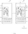
processor 720 may display a preview image for a background screen on thedisplay 710 in response to execution of an application for setting the background screen. Theprocessor 720 may display a preview image for a background screen using an selected image based on a user input for selecting one image. According to one implementation, theprocessor 720 may sequentially (or successively) display areas corresponding to background screens respectively in at least two states of theelectronic device 700 in the selected image as a preview image on thedisplay 710. For example, theprocessor 720 may successively display an area of an image to be displayed as a background screen in a detected current state of theelectronic device 700 and an area of an image to be displayed as a background screen in another state different from the current state as a preview image on thedisplay 710. - When the detected state of the
electronic device 700 is the first state, theprocessor 720 may sequentially (or successively) display a first preview image corresponding to preview for a background screen in the first state and a second preview image corresponding to preview for a background screen in the second state on thedisplay 710 which is in the first state. The first preview image may include a first area of the selected image. The first area may be specified by a user input. The second preview image may include a second area of the selected image. Theprocessor 720 may specify the second area in the selected image based on the specified first area. Theprocessor 720 may specify the first area and the second area including the first area and one area (e.g., a third area) adjacent to the first area. For example, when the detected state of theelectronic device 700 is the first state, theprocessor 720 may display the first area of the selected image as a preview image, and then display the second area including the first area of the image and one area (e.g., the third area) adjacent to the first area as a preview image on thedisplay 710. Theprocessor 720 may change display attribute (e.g., transparency, saturation, or brightness) of at least a portion of the second preview image. - When the detected state of the
electronic device 700 is the second state, theprocessor 720 may sequentially (or successively) display a third preview image corresponding to the second state and a fourth preview image corresponding to the first state on thedisplay 710 which is in the second state. The third preview image may include a fourth area of the selected image. The fourth area may be specified by a user input. The fourth preview image may include a fifth area of the selected image. Theprocessor 720 may specify a fifth area in the selected image based on the specified fourth area. Theprocessor 720 may specify one area in the fourth area as the fifth area. For example, when the detected state of theelectronic device 700 is the second state, theprocessor 720 may display the fourth area of the selected image as a preview image, and then display the fifth area as one area within the fourth area of the image as a preview image. Theprocessor 720 may change display attribute (e.g., transparency, saturation, or brightness) of the fourth preview image. According to one embodiment, the third preview image may be substantially identical to the second preview image, and the fourth preview image may be substantially identical to the first preview image. For example, the fourth area of the image may be substantially equal to the second area of the image, while the fifth area of the image may be substantially equal to the first area of the image. - The
processor 720 may detect a state change of theelectronic device 700. When theprocessor 720 detects a state change of theelectronic device 700, theprocessor 720 may change and display a preview image in a corresponding manner to the state change of theelectronic device 700 on thedisplay 710. For example, when the extended state of theelectronic device 700 is detected, theprocessor 720 may extend and display the first area in the first preview image or the second preview image in proportion to the extension of the display area of thedisplay 710. In another example, when the retracted state of theelectronic device 700 is detected, theelectronic device 700 may reduce and display the third preview image in proportion to the reduction of the display area of thedisplay 710. - Hereinafter, with reference to
Fig. 8 , an electronic device according to one embodiment will be described.Fig. 8 is a diagram illustrating theelectronic device 800 that displayspreview images electronic device 800 may be referred to as an operation of a processor (e.g., theprocessor 120 inFig. 1 ). - Referring to
Fig. 8 , theelectronic device 800 according to one embodiment may display thepreview images display 810. The specified image may be an image selected by a user input for selecting an image. For example, theelectronic device 800 may display thepreview images display 810 in response to execution of a background screen setting application. According to one embodiment, theelectronic device 800 may display a changed (or replaced) image as thepreview images - When the
electronic device 800 according to one embodiment is in the first state (e.g., the retracted state), theelectronic device 800 may display thefirst preview image 820 corresponding to a background screen in the first state state) and thesecond preview image 830 corresponding to a background screen corresponding to the second state (e.g., the extended state) thedisplay 810 which is in the first state. Theelectronic device 800 according to one embodiment may display sequentially (or successively) one and the other of thefirst preview image 820 and thesecond preview image 830 based on a current state of theelectronic device 800. Theelectronic device 800 according to one embodiment may display sequentially thefirst preview image 820 and thesecond preview image 830 when the current state of theelectronic device 800 is the first state. For example, theelectronic device 800 may display thefirst preview image 820 for a specified time duration and then display thesecond preview image 830 on thedisplay 810 which is in the first state. In another example, theelectronic device 800 may alternately display thefirst preview image 820 and thesecond preview image 830 on thedisplay 810. According to one embodiment, theelectronic device 800 may display sequentially (or successively) thefirst preview image 820 and thesecond preview images 830 on thedisplay 810, based on a user input (e.g., touch, swipe) to one user interface (e.g., an icon for background screen setting). - The
first preview image 820 may correspond to a background screen displayed in the first state of theelectronic device 800. A aspect ratio of thefirst preview image 820 may correspond to an aspect ratio of a reduced display area of thedisplay 810 visually exposed in the first state of theelectronic device 800. Thefirst preview image 820 may include at least one area of an image. For example, thefirst preview image 820 may include afirst area 861 of the image. Thefirst area 861 may be specified (or changed) based on a user input (e.g., touch, swipe). - The
second preview image 830 may correspond to a background screen displayed in the second state of theelectronic device 800. The aspect ratio of thesecond preview image 830 may correspond to an aspect ratio of an enlarged display area of thedisplay 810 visually exposed in the second state of theelectronic device 800. Thesecond preview image 830 may include thefirst area 861 of the image and at least one area adjacent to thefirst area 861. According to one embodiment, thesecond preview image 830 may include thefirst area 861 of the image and one area of the image adjacent to thefirst area 861 of the image in an extending direction (e.g., +x direction) of thedisplay 810 in the second state of theelectronic device 800. For example, thesecond preview image 830 may include asecond area 862 composed of thefirst area 861 of the image, and athird area 863 adjacent to thefirst area 861. Thedisplay 810 of theelectronic device 800 may extend in one direction (e.g., +x direction). In this case, theelectronic device 800 may specify thefirst area 861 of the image and thethird area 863 of the image adjacent to thefirst area 861 in the extending direction (e.g., the +x direction) as thesecond area 862. However, the extending direction of thedisplay 810 is not limited as shown inFig. 8 . For example, thedisplay 810 may extend in the -x direction or the y direction. In another example, thedisplay 810 may extend in multiple directions. - The
electronic device 800 may apply a specified effect when thefirst preview image 820 has been switched to thesecond preview image 830. For example, theelectronic device 800 may display thefirst area 861 of the image, and may display thethird area 863 of the image in addition to thefirst area 861 such that thethird area 863 gradually appears in the extending direction (e.g., + x direction). Theelectronic device 800 according to one embodiment may use thedisplay 810 to set the display attribute (e.g., transparency, saturation or brightness) of at least a portion of thesecond area 862 of the image in thesecond preview image 830 to be different from that of a remaining portion of thesecond area 862. Theelectronic device 800 may display thefirst area 861 of the image based on first display attribute, and display thethird area 863 based on second display attribute that is at least partially different from the first display attribute. Theelectronic device 800 according to one embodiment may display the image such that the transparency of thethird area 863 is higher than that of thefirst area 861. For example, theelectronic device 800 may set the transparency of thefirst area 861 of the image to 0% and the transparency of thethird area 863 to 50% and display the first and third areas on thedisplay 810. When theelectronic device 800 which is in the first state displays thesecond preview image 830 corresponding to the second state, theelectronic device 800 may set the display attribute of thefirst area 861 and the display attribute of thethird area 863 to be different from each other. Thus, an image area (e.g., the third area 863) that is additionally displayed when thedisplay 810 extends may be intuitively identified by the user. - The
electronic device 800 according to an embodiment may display a user interface(i.e.,first icon 851, and first information 852) related to the background screen setting. For example, the user interface(i.e.,first icon 851, and first information 852) may include afirst icon 851 andfirst information 852 for background screen setting. For example, thefirst information 852 may include "Set a background screen in consideration of a to-be-slidably-extended range". The user interface(i.e.,first icon 851, and first information 852) shown inFig. 8 is only example. The disclosure is not limited to the illustrated example. - When receiving a user input to the
first icon 851 from the user, theelectronic device 800 may specify (or set) an image selected based on thefirst preview image 820 and thesecond preview image 830 as a background screen of theelectronic device 800. For example, theelectronic device 800 may set the background screen in the first state in response to selection of thefirst preview image 820 and set the background screen in the second state in response to selection of thesecond preview image 830. When the background screen has been set by the user input to thefirst icon 851, theelectronic device 800 may display the background screen corresponding to thefirst preview image 820 on thedisplay 810 which in in the retracted state, and may display the background screen corresponding to thesecond preview image 830 on thedisplay 810 which in in the extended state. -
Fig. 9 shows a first area 911 (e.g., thefirst area 861 ofFig. 8 ) of animage 910 included in a first preview image (e.g., thefirst preview image 820 ofFig. 8 ), and a second area 912 (e.g., thesecond area 862 ofFig. 8 ) of theimage 910 included in a second preview image (e.g., thesecond preview image 830 ofFig. 8 ) in an electronic device (e.g., theelectronic device 800 ofFig. 8 ) according to one embodiment. - Referring to
Fig. 9 , the electronic device which is in the first state (e.g., the retracted state) may specify one area of theimage 910 as thefirst area 911 based on a user input (or execution of a background screen setting application). - The electronic device may specify the
second area 912 of theimage 910 based on thefirst area 911. For example, the electronic device may specify thefirst area 911 and thethird area 913 adjacent to thefirst area 911 in one direction (e.g., +x direction) as thesecond area 912. However, a location of thethird area 913 shown inFig. 9 is only an example. The disclosure is not limited thereto. The location of thethird area 913 may be determined based on the extending direction of the display of the electronic device. For example, the electronic device may specify thefirst area 911 and an area adjacent to thefirst area 911 in another direction (e.g., -x direction or y direction) as thethird area 913. - Hereinafter, with reference to
Fig. 10 , an electronic device according to one embodiment will be described.Fig. 10 is a diagram showing theelectronic device 1000 that displays a preview image according to an embodiment of the disclosure. Hereinafter, an operation of the electronic device may be referred to as an operation of a processor (e.g., theprocessor 120 inFig. 1 ). - Referring to
Fig. 10 , anelectronic device 1000 according to one embodiment may displaypreview images display 1010. For example, theelectronic device 1000 may display thepreview images display 1010 in response to execution of the background screen setting application. According to one embodiment, theelectronic device 1000 may display a changed (or replaced) image as thepreview images - While the
electronic device 1000 according to an embodiment is in the second state (e.g., the extended state), theelectronic device 1000 may display athird preview image 1020 corresponding to the background screen in the second state and afourth preview image 1030 corresponding to the background screen in the first state (e.g., the retracted state) on thedisplay 1010. Thethird preview image 1020 may be substantially identical to thesecond preview image 830 ofFig. 8 , while thefourth preview image 1030 may be substantially identical to thefirst preview image 820 ofFig. 8 . Theelectronic device 1000 according to one embodiment may display sequentially (or successively ) one and the other of thethird preview image 1020 and thefourth preview image 1030 based on a current state of theelectronic device 1000. Theelectronic device 1000 according to one embodiment may sequentially display thethird preview image 1020 and thefourth preview image 1030 when the current state of theelectronic device 1000 is the second state. For example, theelectronic device 1000 may display thethird preview image 1020 for a specified time duration and then display thefourth preview image 1030 on thedisplay 1010 which is in the second state. In another example, theelectronic device 1000 may alternately display thethird preview image 1020 and thefourth preview image 1030 on thedisplay 1010. According to one embodiment, theelectronic device 1000 may display sequentially (or successively) thethird preview image 1020 and the fourth preview image ( 1030) on thedisplay 1010, based on the user input (e.g., touch, swipe) to an icon (e.g., an icon for background screen setting). - The
third preview image 1020 may correspond to a background screen displayed in the second state of theelectronic device 1000. An aspect ratio of thethird preview image 1020 may correspond to an aspect ratio of an extended display area of thedisplay 1010 visually exposed in the second state of theelectronic device 1000. Thethird preview image 1020 may include at least one area of the image. For example, thethird preview image 1020 may include afourth area 1061 of the image. Thefourth area 1061 may be substantially the same as thesecond area 862 ofFig. 8 . Thefourth area 1061 may be specified (or changed) by a user input (e.g., touch, swipe). - The
fourth preview image 1030 may correspond to a background screen displayed in the first state of theelectronic device 1000. An aspect ratio of thefourth preview image 1030 may correspond to an aspect ratio of the reduced display area of thedisplay 1010 visually exposed in the first state of theelectronic device 1000. Thefourth preview image 1030 may include afifth area 1062 of the image. Thefifth area 1062 may be substantially the same as thefirst area 861 ofFig. 8 . Thefifth area 1062 of the image may be included in one area within thefourth area 1061. According to one embodiment, thefourth area 1061 may further include one area of the image adjacent to thefifth area 1062 of the image in the extending direction (e.g., +x direction) of thedisplay 1010. - The
electronic device 1000 may apply a specified effect when the device switches thethird preview image 1020 to thefourth preview image 1030. For example, theelectronic device 1000 may display thefourth area 1061 of the image, and then may display thefifth area 1062 such that an area of thefourth area 1061 other thanfifth area 1062 gradually disappears in a retracting direction (e.g., - x direction). - The
electronic device 1000 according to an embodiment may change the display attribute (e.g., transparency, saturation or brightness) of thefourth preview image 1030, and may display thefourth preview image 1030 to which the changed display attribute is applied on thedisplay 1010. Theelectronic device 1000 may display thethird preview image 1020 based on first display attribute, and display thefourth preview image 1030 based on second display attribute which is at least partially different from the first display attribute. Theelectronic device 1000 according to one embodiment may display thefourth preview image 1030 at transparency higher than transparency of thethird preview image 1020. For example, theelectronic device 1000 may set the transparency of thethird preview image 1020 to 0 % and set the transparency of thefourth preview image 1030 to 50 % and display the same on thedisplay 1010. - The
electronic device 1000 according to an embodiment may display an user interface(i.e.,first icon 1051, and first information 1052) related to background screen setting. For example, the user interface(i.e.,first icon 1051, and first information 1052) may include afirst icon 1051 andfirst information 1052 for background screen setting. For example, thefirst information 1052 may include "Set a background screen in consideration of a to-be-slidably-retracted range". Theuser interface Fig. 10 is only an example. The disclosure is not limited to the illustrated example. - Upon receiving the user input to the
first icon 1051 from the user, theelectronic device 1000 may specify (set) an image selected based on thethird preview image 1020 and thefourth preview image 1030 as the background screen of theelectronic device 1000. For example, theelectronic device 1000 may set the background screen in the second state in response to selection of thethird preview image 1020 and set the background screen in the first state in response to selection of thefourth preview image 1030. When the background screen has been set by the user input to thefirst icon 1051, theelectronic device 1000 may display a background screen corresponding to thethird preview image 1020 on thedisplay 1010 which in in the extended state, and a background screen corresponding to thefourth preview image 1030 on thedisplay 1010 which is in the retracted state. -
Fig. 11 shows a fourth area 1111 (e.g., thefourth area 1061 ofFig. 10 ) of animage 1110 included in a third preview image (e.g., thethird preview image 1020 ofFig. 10 ), and a fifth area 1112 (e.g., thefifth area 1062 ofFig. 10 ) of theimage 1110 included in a fourth preview image (e.g., thefourth preview image 1030 ofFig. 10 ) in an electronic device (e.g., the electronic device (1000) ofFig. 10 ) according to one embodiment. - Referring to
Fig. 11 , the electronic device which is in the second state (e.g., the extended state) may specify one area of animage 1110 as afourth area 1111 based on a user input (or execution of a background screen setting application). - The electronic device may specify a
fifth area 1112 of theimage 1110 based on thefourth area 1111. The electronic device may specify a partial area othefourth area 1111 in the image as thefifth area 1112. A location of thefifth area 1112 in thefourth area 1111 may be determined based on the retracting direction of the display of the electronic device. For example, the electronic device may specify one area located in the retracting direction (e.g., - x direction) of the display in thefourth area 1111 of the image as thefifth area 1112 and specify one area located in the extending direction (e.g., +x direction) of the display in thefourth area 1111 of the image as thesixth area 1113. For example, thefourth area 1111 of the image may include thefifth area 1112 and thesixth area 1113 adjacent to thefifth area 1112. However, positions of thefourth area 1111 and thefifth area 1112 shown inFig. 11 are only examples. The disclosure is not limited thereto. - Hereinafter, with reference to
Fig. 12 , an electronic device according to one embodiment will be described.Fig. 12 is a view showing a preview image according to a state of the electronic device according to an embodiment of the disclosure. - Referring to
Fig. 12 , a state of theelectronic device 1200 according to an embodiment may include a first state 1201 (e.g., a retracted state) in which thedisplay 1210 has retracted, thesecond state 1203 in which thedisplay 1210 has extended (e.g., a extended state) and a third state 1202 (e.g., an intermediate state) in which a portion of thedisplay 1210 has retracted or extended. As the state of theelectronic device 1200 is gradually changed to thefirst state 1201, thethird state 1202, and thesecond state 1203, the display area of thedisplay 1210 may be gradually enlarged. - The
electronic device 1200 of thefirst state 1201 may display a preview image 1220 (e.g., thesecond preview image 830 ofFig. 8 ) on thedisplay 1210. Thepreview image 1220 displayed on thedisplay 1210 of theelectronic device 1200 in thefirst state 1201 may include asecond area 1222 including afirst area 1221 of a selected image and athird area 1223 adjacent to thefirst area 1221 in an extending direction (e.g., +x direction) of thedisplay 1210. Thefirst area 1221 of the image displayed on thedisplay 1210 of theelectronic device 1200 in thefirst state 1201 may correspond to the background screen displayed in thefirst state 1201 of theelectronic device 1200. Thesecond area 1222 of the image may correspond to a background screen displayed in thesecond state 1203 of theelectronic device 1200. An aspect ratio of thefirst area 1221 of the image may correspond to an aspect ratio of a display area of thedisplay 1210 visually exposed in thefirst state 1201 of theelectronic device 1200. An aspect ratio of thesecond area 1222 of the image may correspond to an aspect ratio of the enlarged display area of thedisplay 1210 visually exposed in thesecond state 1203 of theelectronic device 1200. - The
electronic device 1200 which is in thefirst state 1201 may use thedisplay 1210 to set display attribute (e.g., transparency, saturation, brightness of at least a portion of thesecond area 1222 of the image in thepreview image 1220 to be different from that of a remaining portion thereof. Theelectronic device 1200 which is in thefirst state 1201 may display thefirst area 1221 of the image based on first display attribute, and may display thethird area 1223 based on second display attribute which is at least partially different from the first display attribute. Theelectronic device 1200 according to one embodiment may set the transparency of thethird area 1223 of the image to be higher than that of thefirst area 1221. For example, theelectronic device 1200 may set the transparency of thefirst area 1221 of the image to 0 % and the transparency of thethird area 1223 to 50 % and display the same on thedisplay 1210. Theelectronic device 1200 according to one embodiment may extend and display an area displayed based on the display attribute in thepreview image 1220 in proportion to the extension of the display area of thedisplay 1210 as the state of theelectronic device 1200 is changed from thefirst state 1201 to thesecond state 1203. - The
electronic device 1200 of thethird state 1202 may display apreview image 1230 on thedisplay 1210. Thepreview image 1230 displayed on thedisplay 1210 of theelectronic device 1200 in thethird state 1202 may include asecond area 1222 including thesixth area 1224 of the selected image and aseventh area 1225 adjacent to thesixth area 1224 in the extending direction (e.g., +x direction) of thedisplay 1210. In thepreview image 1230 displayed on thedisplay 1210 of theelectronic device 1200 in thethird state 1202, thesixth area 1224 may correspond to the background screen displayed when thethird state 1202 is a current state of theelectronic device 1200. Thesixth area 1224 may include thefirst area 1221 and one area adjacent to thefirst area 1221 in the extending direction of thedisplay 1210. Theseventh area 1225 may be a remaining area except for thesixth area 1224 in thesecond area 1222. - The
electronic device 1200 of thethird state 1202 may display thesixth area 1224 of the image based on first display attribute, and display theseventh area 1225 based on second display attribute which is at least partially different from the first display attribute. Theelectronic device 1200 according to one embodiment may set the transparency of theseventh area 1225 of the image to be higher than that of thesixth area 1224. For example, theelectronic device 1200 may set the transparency of thesixth area 1224 of the image to 0% and the transparency of theseventh area 1225 to 50% and display the same on thedisplay 1210. - As the
electronic device 1200 according to an embodiment is gradually changed to thefirst state 1201, thethird state 1202 and thesecond state 1203, theelectronic device 1200 may display thepreview image 1230 in a corresponding manner to a varying state of theelectronic device 1200. Theelectronic device 1200 may extend and display an area (e.g., thefirst area 1221 and the sixth area 1224) of the image displayed based on the first display attribute in proportion to the extension of thedisplay 1210. As thedisplay 1210 extends, theelectronic device 1200 may reduce and display an area (e.g., thethird area 1223 and the seventh area 1225 ) of the image displayed based on the second display attribute. - The
electronic device 1200 which is in thesecond state 1203 may display the preview image 1240 (e.g., thethird preview image 1020 inFig. 10 ) corresponding to the background screen displayed in thesecond state 1203 on thedisplay 1210. - As the
electronic device 1200 according to one embodiment is gradually changed to thefirst state 1201, thethird state 1202 and thesecond state 1203, theelectronic device 1200 may display thepreview images electronic device 1200. - The
electronic device 1200 which is in each of thefirst state 1201, thethird state 1202 and thesecond state 1203 may display user interfaces (i.e.,first icon 1251,first information 1252, and second information 1253) related to the background screen setting on thedisplay 1210. Theelectronic device 1200 which is in each of thefirst state 1201 and thethird state 1202 may display afirst icon 1251 andfirst information 1252 for setting the background screen on thedisplay 1210. For example, thefirst information 1252 may include "Set a background screen in consideration of a to-be-slidably-retracted range". Theelectronic device 1200 which is in thesecond state 1203 may display thefirst icon 1251 andsecond information 1253 for setting the background screen on thedisplay 1210. For example, thesecond information 1253 may include "Set a background screen in consideration of a to-be-extracted range of a slide". Theuser interfaces Fig. 12 are only examples. The disclosure is not limited to the illustrated examples. - Hereinafter, with reference to
Fig. 13 , an electronic device according to one embodiment will be described.Fig. 13 is a view showing a preview image according to a state of the electronic device according to an embodiment of the disclosure. - Referring to
Fig. 13 , a state of theelectronic device 1300 according to an embodiment may include a second state 1301 (e.g., an extended state) in which adisplay 1310 has extended, a first state 1303 (e.g., a retracted state) in which thedisplay 1310 has retracted and a third state 1302 (e.g., an intermediate state) in which a portion of thedisplay 1310 has retracted or extended. As the state of theelectronic device 1300 is gradually changed to thesecond state 1301, thethird state 1302, and thefirst state 1303, the display area of thedisplay 1310 may be gradually reduced. Theelectronic device 1300 according to one embodiment may reduce anddisplay preview images display 1310 as the state of the device is changed from thesecond state 1301 to thefirst state 1303. - The
electronic device 1300 which is in thesecond state 1301 may display apreview image 1320 corresponding to thesecond state 1301 on thedisplay 1310. Thepreview image 1320 displayed on thedisplay 1310 of theelectronic device 1300 in thesecond state 1301 may correspond to the preview image of the background screen displayed in thesecond state 1301 of theelectronic device 1300. Thepreview image 1330 displayed on thedisplay 1310 of theelectronic device 1300 in thesecond state 1301 may include aneighth area 1321 of a selected image. - The
electronic device 1300 which is in thethird state 1302 may display thepreview image 1330 on thedisplay 1310. Thepreview image 1330 displayed on thedisplay 1310 of theelectronic device 1300 in thethird state 1302 may correspond to the background screen displayed in thethird state 1302 of theelectronic device 1300. Thepreview image 1330 may be free of one area which is present in theeighth area 1321 in thepreview image 1320. For example, thepreview image 1330 displayed on thedisplay 1310 of theelectronic device 1300 in thethird state 1302 may include aninth area 1322 corresponding to one area within theeighth area 1321 of the image. As theelectronic device 1300 according to one embodiment is gradually changed to thesecond state 1301, thethird state 1302 and thefirst state 1303, theelectronic device 1300 may display thepreview images electronic device 1300 may reduce and display thepreview image 1330 in proportion to the retraction of thedisplay 1310. - The
electronic device 1300 which is in thefirst state 1303 may display thepreview image 1340 corresponding to thefirst state 1303 on thedisplay 1310. Thepreview image 1340 displayed on thedisplay 1310 of theelectronic device 1300 in thefirst state 1303 may correspond to the preview image of the background screen displayed in thefirst state 1303 of theelectronic device 1300. Thepreview image 1340 may be free of one area which is present in theninth area 1322 in thepreview image 1330. For example, thepreview image 1340 displayed on thedisplay 1310 of theelectronic device 1300 in thefirst state 1303 may include atenth area 1323 corresponding to one area within theninth area 1322 of the image. - As the
electronic device 1300 according to one embodiment is gradually changed to thesecond state 1301, thethird state 1302 and thefirst state 1303, theelectronic device 1300 may display thepreview images electronic device 1300. - The
electronic device 1300 which is in each of thefirst state 1301, thethird state 1302 and thesecond state 1303 may display user interface (i.e.,first icon 1351,first information 1352, and second information 1353) related to the background screen setting on thedisplay 1310. Theelectronic device 1300 which is in each of thesecond state 1301 and thethird state 1302 may display afirst icon 1351 andfirst information 1352 for setting the background screen on thedisplay 1310. For example, thefirst information 1352 may include "Set a background screen in consideration of a to-be-slidably-retracted range". Theelectronic device 1300 which is in thefirst state 1303 may display thefirst icon 1351 andsecond information 1353 for setting the background screen on thedisplay 1310. For example, thesecond information 1353 may include "Set a background screen in consideration of a to-be-slidably-extended range". Theuser interfaces Fig. 13 are only examples. The disclosure is not limited to the illustrated examples. -
Fig. 14 is a diagram showing a background screen setting screen in an electronic device according to an embodiment of the disclosure. Referring toFig. 14 , anelectronic device 1400 according to one embodiment may display a preview image 1420 (e.g., the preview image (820, 830) inFig. 8 ) and a user interface (i.e.,first icon 1451,first information 1452, second information 1460) for setting the background screen. The user interface (i.e.,first icon 1451,first information 1452, and second information 1460) may include afirst icon 1451,first information 1452, andsecond information 1460. For example, thefirst information 1452 may include "Set a background screen in consideration of a slidably-extended range". Thesecond information 1460 may include a guide phrase that guide the user to actually slide the electronic device on the background screen setting screen. For example, thesecond information 1460 may include a guide phrase including content that a preview image displaying a background screen that changes according to a change in the state of the electronic device is displayed. For example, thesecond information 1460 may include "if you slide the device, you may see change of a background screen in a preview". - Hereinafter, with reference to
Fig. 15 , an operation configuration of an electronic device according to one embodiment it will be described.Fig. 15 is a flowchart showing an operation configuration of an electronic device according to an embodiment of the disclosure. Hereinafter, an operation of the electronic device may be referred to as an operation of a processor (e.g., theprocessor 120 inFig. 1 ). - Referring to
Fig. 15 , inoperation 1510, the electronic device according to one embodiment may detect a current state of the electronic device. For example, the electronic device may detect a current state of the electronic device using a sensor (e.g., thesensor module 176 ofFig. 1 ). According to an embodiment, the electronic device may acquire state information about the current state of the electronic device. The electronic device according to one embodiment may identify the extended or retracted state of the display. - In
operation 1520, the electronic device according to one embodiment may set a first area and a second area of a specified image based on the sensed current state (or acquired state information) of the electronic device. The specified image may be an image selected by a user input for selecting an image. When the current state of the electronic device detected inoperation 1510 corresponds to the first state (e.g., the retracted state), inoperation 1520, the electronic device may set one area of the specified image displayed as a background screen in the first state as the first area, and one area of the specified image displayed as a background screen in the second state (e.g., the extended state) as the second area. For example, the first area of the image may be set based on a user input. The electronic device may set the second area including the first area and at least one area adjacent to the first area based on the set first area. When the current state of the electronic device detected inoperation 1510 corresponds to the second state (e.g., the extended state), inoperation 1520, the electronic device may set one area of the specified image displayed as the background screen in the second state as the second area and one area of the specified image displayed as a background screen in the first state (e.g., the retracted state) as the first area. For example, the second area of the image may be set based on a user input. The electronic device may set the first area located in the second area based on the second area. - In
operation 1530, the electronic device according to one embodiment may display the first preview image including the first area of the image and the second preview image including the second area of the image on the display. The first preview image may correspond to the background screen displayed in the first state, and the second preview image may correspond to the background screen displayed in the second state. The electronic device according to one embodiment may sequentially display the first preview image and the second preview image. For example, the electronic device may display the first preview image for a specified time duration and then display the second preview image on the display. In another example, the electronic device may display the second preview image for a specified time duration and then display the first preview image on the display. In still another example, the electronic device may alternately display the first preview image and the second preview image on the display. - Hereinafter, with reference to
Fig. 16 , an operation configuration of the electronic device according to one embodiment will be described.Fig. 16 is a flowchart showing an operation configuration of an electronic device according to an embodiment of the disclosure. Hereinafter, an operation of the electronic device may be referred to as an operation of the processor (e.g., theprocessor 120 inFig. 1 ). - Referring to
Fig. 16 , inoperation 1610, the electronic device according to one embodiment may display a first preview image including a first area of an image and a second preview image including a second area of the image on the display. The first preview image may correspond to a background screen displayed in the first state (e.g., the retracted state), and the second preview image may correspond to a background screen displayed in the second state (e.g., the extended state). For example, the electronic device may display the first preview image for a specified timed duration and then display the second preview image on the display. In another example, the electronic device may display the second preview image for a specified time duration and then display the first preview image on the display. In still another example, the electronic device may alternately display the first preview image and the second preview image on the display. - In
operation 1620, the electronic device according to one embodiment may detect (or identify) whether the state of the electronic device has changed. When the change in the state of the electronic device is not detected (NO), the electronic device may performoperation 1610. - When the state change of the electronic device is detected (YES), in
operation 1630, the electronic device may change the preview image based on the changed state and display the changed preview image on the display. For example, when the extended state of the electronic device is detected, the electronic device according to one embodiment may extend and display the first area in the preview image of the first state and/or the third state in proportion to the extension of the display area of the display. In another example, when the retracted state of the electronic device is detected, the electronic device according to one embodiment may reduce and display the preview image in the second state in proportion to the reduction of the display area of the display. - Hereinafter, with reference to
Fig. 17 , a method in which an electronic device (e.g., theelectronic device 101 ofFig. 1 ) according to one embodiment executes a background screen setting application will be described.Fig. 17 is a diagram showing that the electronic device executes the background screen setting application according to an embodiment of the disclosure. - Referring to
Fig. 17 , the electronic device according to one embodiment may display apreset background screen 1710 and at least oneicon 1711 for execution of an application (e.g., theapplication 146 ofFig. 3 ) on a first screen 1701 (e.g., a home screen). - Upon receiving a specified first user input 1715 (e.g., two drag inputs in opposite directions) to the
first screen 1701, the electronic device according to one embodiment may display a first user interface 1721 (e.g., a background screen setting icon) for execution of a background screen setting application on asecond screen 1702. - Upon receiving a
second user input 1725 to thefirst user interface 1721, the electronic device according to one embodiment may display at least oneimage 1731 on athird screen 1703. For example, the electronic device may display at least oneimage 1731 stored in a memory (e.g., thememory 130 ofFig. 1 ) by an album (e.g., the album (375) inFig. 3 ) application. - Upon receiving a
third user input 1735 to one of the at least oneimage 1731, the electronic device according to one embodiment may display, on thefourth screen 1704, asecond user interface 1741 including a list of screens for which background screens are to be set. For example, thesecond user interface 1741 may include "Home screen", "Lock screen", and "Lock and Home screens". - Upon receiving a
fourth user input 1745 to the second user interface 1741 (e.g., Home screen), a background screen setting application may be executed. In response to the execution of the background screen setting application, the electronic device according to one embodiment may display, on a fifth screen 1705 (e.g., a background screen setting screen), a preview image (1751) for the background screen to be set based on a selected image, and an icon (1752) for background screen setting (e.g., thefirst icon 851 ofFig. 8 , thefirst icon 1051 ofFig. 10 , thefirst icon 1251 ofFig. 12 , thefirst icon 1351 ofFig. 13 , or thefirst icon 1451 ofFig. 14 ). - Hereinafter, with reference to
Fig. 18 , a method in which an electronic device (e.g., theelectronic device 101 ofFig. 1 ) according to one embodiment executes a background screen setting application is described.Fig. 18 is a diagram showing that the electronic device executes the background screen setting application according to an embodiment of the disclosure. - Referring to
Fig. 18 , is in response to execution of an album (e.g., the album (375) inFig. 3 ) application, the electronic device according to one embodiment may display at least oneimage 1811 on afirst screen 1801. - Upon receiving a
first user input 1815 to one of the at least oneimage 1811, the electronic device according to one embodiment may display a selectedimage 1821 and afirst icon 1822 on asecond screen 1802. - Upon receiving a
second user input 1825 to thefirst icon 1822, the electronic device according to one embodiment may display afirst user interface 1831 including at least one execution list that may be performed on the selectedimage 1821 on athird screen 1803. For example, thefirst user interface 1831 may include "Details", "Set as wallpaper", "Set as Always On Display Image", "Move to Secure Folder", and "Print". - Upon receiving a
third user input 1835 to the first user interface 1831 (e.g., Set as wall paper), the electronic device according to one embodiment may display, on afourth screen 1804, asecond user interface 1841 including a list of screens for which background screens is to be set. For example, thesecond user interface 1841 may include "Home screen", "Lock screen", and "Lock and Home screens". - Upon receiving a
fourth user input 1845 to the second user interface 1841 (e.g., Home screen), a background screen setting application may be executed. In response to execution of the background screen setting application, the electronic device according to one embodiment may display, on a fifth screen 1805 (e.g., a background screen setting screen), a preview image 1851 (e.g., thepreview images Fig. 8 ) for the background screen to be set based on a selected image, and anicon 1852 for background screen setting (e.g., thefirst icon 851 inFig. 8 ), thefirst icon 1051 inFig. 10 , thefirst icon 1251 inFig. 12 , thefirst icon 1351 inFig. 13 , or thefirst icon 1451 inFig. 14 ). - An electronic device (e.g., the electronic device 101 of
Fig. 1 , the electronic device 400 ofFig. 4 , the electronic device 600 ofFig. 6 , the electronic device 700 ofFig. 7 , the electronic device 800 ofFig. 8 , the electronic device 1000 inFig. 10 , the electronic device 1200 inFig. 12 , the electronic device 1300 inFig. 13 or the electronic device(1400) inFig. 14 ), according to an embodiment may include a display (e.g., the display 210 inFig. 2 , the display 450 inFig. 4 , the display 650 inFig. 6 , the display 710 inFig. 7 , the display 810 inFig. 8 , the display 1010 inFig. 10 , the display inFig. 12 1210, or the display 1310 inFig. 13 ) having a display area, wherein a size of the display area visually exposed in a first state of the electronic device is reduced and a size of the display area visually exposed in a second state of the electronic device is enlarged; and a processor (e.g., the processor 120 inFig. 1 or the processor 720 inFig. 7 ) operatively connected to the display, wherein the processor may be configured to acquire state information of the electronic device, successively display one and the other of first and second preview images on the display, based on the state information of the electronic device, wherein the first preview image (e.g., the first preview image 820 ofFig. 8 , the fourth preview image 1030 ofFig. 10 , or the preview image 1340 ofFig. 13 ) includes a first area (e.g., the first area 861 ofFig. 8 , the first area 911 ofFig. 9 , the fifth area 1062 ofFig. 10 , the fifth area 1112 ofFig. 11 , the first area 1221 ofFig. 12 , or the tenth area 1323 ofFig. 13 ) of a specified image and corresponds to a preview image of a background screen in the first state, wherein the second preview image (e.g., the second preview image 830 ofFig. 8 , the third preview image 1020 ofFig. 10 , or the preview images 1220, 1230, and 1240 or the preview image 1320 ofFig. 13 ) includes a second area (e.g., the second area 862 ofFig. 8 , the second area 912 ofFig. 9 , the fourth area 1061 ofFig. 10 ) ), the fourth area 1111 ofFig. 11 , the second area 1222 ofFig. 12 , or the eighth area 1321 ofFig. 13 ) extending from the first area of the image, and corresponds to a preview image of a background screen in the second state, and specify the image as a background screen, based on a first user input. - According to one embodiment, the second area may include the first area and a third area (e.g., the
third area 863 inFig. 8 , thethird area 913 inFig. 9 , thesixth area 1113 ofFig. 11 , or thethird area 1223 ofFig. 12 ) adjacent to the first area. - According to one embodiment, the processor may be configured to display the first preview image on the display having the first state when a state of the electronic device is the first state, and display the second preview image such that the third area gradually appears in one direction.
- According to one embodiment, the processor may be configured to display the second preview image on the display having the second state when a state of the electronic device is the second state, and display the first preview image such that the third area gradually disappears in one direction.
- According to one embodiment, when a state of the electronic device is the first state, the processor may be configured to display the first area of the image in the second preview image based on first display attribute, and display the third area of the image in the second preview image based on second display attribute at least partially different from the first display attribute.
- According to one embodiment, the processor may be configured to extend and display an area of the image displayed based on the first display attribute, in proportion to extension of the display area of the display as the state of the electronic device has changed from the first state to the second state.
- According to one embodiment, when a state of the electronic device is the first state, the processor may be configured to specify one area of the image as the first area, based on a second user input, and specify the second area in the image, based on the specified first area and an extending direction of the display.
- According to one embodiment, when a state of the electronic device is the second state, the processor may be configured to display the first preview image based on first display attribute, and display the second preview image based on second display attribute at least partially different from the first display attribute.
- According to one embodiment, the processor may be configured to reduce and display the second preview image, in proportion to reduction of the display area of the display as the state of the electronic device has changed from the second state to the first state.
- According to one embodiment, when a state of the electronic device is the second state, the processor may be configured to specify one area of the image as the second area, based on a second user input, and specify the first area in the image, based on the specified second area and a retracting direction of the display.
- According to one embodiment, an aspect ratio of the first area of the image corresponds to an aspect ratio of the display area of the display visually exposed in the first state, wherein an aspect ratio of the second area of the image corresponds to an aspect ratio of the display area of the display visually exposed in the second state.
- According to one embodiment, the processor may be configured to, when the electronic device is in the first state, display the first preview image and, subsequently, display the second preview image, or when the electronic device is in the second state, display the second preview image and, subsequently, display the first preview image.
- According to one embodiment, the processor may be configured to display, on the display, a user interface (e.g., the
second information 1460 ofFig. 14 ) including a guide phrase including an indication that a preview image representing a background screen varying according to change in the state of the electronic device is displayed. - According to one embodiment, the processor may be configured to display a user interface (e.g., the
first icon 851 inFig. 8 , thefirst icon 1051 inFig. 10 , thefirst icon 1251 inFig. 12 , thefirst icon 1351 inFig. 13 , or thefirst icon 1451 inFig. 14 ) related to background screen setting on the display, and specify the image as a background screen, based on the first user input to the user interface. - A method for controlling an electronic device (e.g., the
electronic device 101 ofFig. 1 , theelectronic device 400 ofFig. 4 , theelectronic device 600 ofFig. 6 , theelectronic device 700 ofFig. 7 , theelectronic device 800 ofFig. 8 , theelectronic device 1000 inFig. 10 , theelectronic device 1200 inFig. 12 , theelectronic device 1300 inFig. 13 or the electronic device(1400) inFig. 14 ) including a flexible display (e.g., thedisplay 210 inFig. 2 , thedisplay 450 inFig. 4 , thedisplay 650 inFig. 6 , thedisplay 710 inFig. 7 , thedisplay 810 inFig. 8 , thedisplay 1010 inFig. 10 , the display inFig. 12 1210, or thedisplay 1310 inFig. 13 ) having a display area may be disclosed, wherein a size of the display area visually exposed in a first state of the electronic device is reduced and a size of the display area visually exposed in a second state of the electronic device is enlarged. The method may include acquiring state information of the electronic device, successively displaying one and the other of first and second preview images on the display, based on the state information of the electronic device, wherein the first preview image (e.g., the first preview image 820 ofFig. 8 , the fourth preview image 1030 ofFig. 10 , or the preview image 1340 ofFig. 13 ) includes a first area (e.g., the first area 861 ofFig. 8 , the first area 911 ofFig. 9 , the fifth area 1062 ofFig. 10 , the fifth area 1112 ofFig. 11 , the first area 1221 ofFig. 12 , or the tenth area 1323 ofFig. 13 ) of a specified image and corresponds to a preview image of a background screen in the first state, wherein the second preview image (e.g., the second preview image 830 ofFig. 8 , the third preview image 1020 ofFig. 10 , or the preview images 1220, 1230, and 1240 or the preview image 1320 ofFIG. 13 ) includes a second area (e.g., the second area 862 ofFig. 8 , the second area 912 ofFig. 9 , the fourth area 1061 ofFig. 10 ) ), the fourth area 1111 ofFig. 11 , the second area 1222 ofFig. 12 , or the eighth area 1321 ofFig. 13 ) extending from the first area of the image, and corresponds to a preview image of a background screen in the second state, and specifying the image as a background screen, based on a first user input. - According to one embodiment, the second area may include the first area and a third area (e.g., the
third area 863 inFig. 8 , thethird area 913 inFig. 9 , thesixth area 1113 ofFig. 11 , or thethird area 1223 ofFig. 12 ) adjacent to the first area. - According to one embodiment, the method may include displaying the first preview image on the display having the first state when a state of the electronic device is the first state, and displaying the second preview image such that the third area gradually appears in one direction.
- According to one embodiment, the method may include displaying the second preview image on the display having the second state when a state of the electronic device is the second state, and displaying the first preview image such that the third area gradually disappears in one direction.
- According to one embodiment, when a state of the electronic device is the first state, the device may display the first area of the image in the second preview image based on first display attribute, and display the third area of the image in the second preview image based on second display attribute at least partially different from the first display attribute.
- According to one embodiment, the method may include extending and displaying an area of the image displayed based on the first display attribute, in proportion to extension of the display area of the display as the state of the electronic device has changed from the first state to the second state.
- The electronic device according to various embodiments may be one of various types of electronic devices. The electronic devices may include, for example, a portable communication device (e.g., a smartphone), a computer device, a portable multimedia device, a portable medical device, a camera, a wearable device, or a home appliance. According to an embodiment of the disclosure, the electronic devices are not limited to those described above.
- It should be appreciated that various embodiments of the disclosure and the terms used therein are not intended to limit the technological features set forth herein to particular embodiments and include various changes, equivalents, or replacements for a corresponding embodiment. With regard to the description of the drawings, similar reference numerals may be used to refer to similar or related elements. It is to be understood that a singular form of a noun corresponding to an item may include one or more of the things, unless the relevant context clearly indicates otherwise. As used herein, each of such phrases as "A or B," "at least one of A and B," "at least one of A or B," "A, B, or C," "at least one of A, B, and C," and "at least one of A, B, or C," may include any one of, or all possible combinations of the items enumerated together in a corresponding one of the phrases. As used herein, such terms as "1st" and "2nd," or "first" and "second" may be used to simply distinguish a corresponding component from another, and does not limit the components in other aspect (e.g., importance or order). It is to be understood that if an element (e.g., a first element) is referred to, with or without the term "operatively" or "communicatively", as "coupled with," "coupled to," "connected with," or "connected to" another element (e.g., a second element), it means that the element may be coupled with the other element directly (e.g., wiredly), wirelessly, or via a third element.
- As used in connection with various embodiments of the disclosure, the term "module" may include a unit implemented in hardware, software, or firmware, and may interchangeably be used with other terms, for example, "logic," "logic block," "part," or "circuitry". A module may be a single integral component, or a minimum unit or part thereof, adapted to perform one or more functions. For example, according to an embodiment, the module may be implemented in a form of an application-specific integrated circuit (ASIC).
- Various embodiments as set forth herein may be implemented as software (e.g., the program 140) including one or more instructions that are stored in a storage medium (e.g.,
internal memory 136 or external memory 138) that is readable by a machine (e.g., the electronic device 101). For example, a processor (e.g., the processor 120) of the machine (e.g., the electronic device 101) may invoke at least one of the one or more instructions stored in the storage medium, and execute it, with or without using one or more other components under the control of the processor. This allows the machine to be operated to perform at least one function according to the at least one instruction invoked. The one or more instructions may include a code generated by a complier or a code executable by an interpreter. The machine-readable storage medium may be provided in the form of a non-transitory storage medium. Wherein, the term "non-transitory" simply means that the storage medium is a tangible device, and does not include a signal (e.g., an electromagnetic wave), but this term does not differentiate between where data is semi-permanently stored in the storage medium and where the data is temporarily stored in the storage medium. - According to an embodiment, a method according to various embodiments of the disclosure may be included and provided in a computer program product. The computer program product may be traded as a product between a seller and a buyer. The computer program product may be distributed in the form of a machine-readable storage medium (e.g., compact disc read only memory (CD-ROM)), or be distributed (e.g., downloaded or uploaded) online via an application store (e.g., PlayStore™), or between two user devices (e.g., smart phones) directly. If distributed online, at least part of the computer program product may be temporarily generated or at least temporarily stored in the machine-readable storage medium, such as memory of the manufacturer's server, a server of the application store, or a relay server.
- According to various embodiments, each component (e.g., a module or a program) of the above-described components may include a single entity or multiple entities, and some of the multiple entities may be separately disposed in different components. According to various embodiments, one or more of the above-described components may be omitted, or one or more other components may be added. Alternatively or additionally, a plurality of components (e.g., modules or programs) may be integrated into a single component. In such a case, according to various embodiments, the integrated component may still perform one or more functions of each of the plurality of components in the same or similar manner as they are performed by a corresponding one of the plurality of components before the integration. According to various embodiments, operations performed by the module, the program, or another component may be carried out sequentially, in parallel, repeatedly, or heuristically, or one or more of the operations may be executed in a different order or omitted, or one or more other operations may be added.
- While the disclosure has been shown and described with reference to various embodiments thereof, it will be understood by those skilled in the art that various changes in form and details may be made therein without departing from the spirit and scope of the disclosure as defined by the appended claims and their equivalents.
Claims (15)
- An electronic device comprising:a display having a display area, wherein a size of the display area visually exposed in a first state of the electronic device is reduced and a size of the display area visually exposed in a second state of the electronic device is enlarged; anda processor operatively connected to the display,wherein the processor is configured to:acquire state information of the electronic device,successively display a first preview image and a second preview image on the display, based on the state information of the electronic device, wherein the first preview image comprises a first area of a specified image and corresponds to a preview image of a background screen in the first state, wherein the second preview image comprises a second area extending from the first area of the image, and corresponds to a preview image of a background screen in the second state, andspecify the image as a background screen, based on a first user input.
- The electronic device of claim 1, wherein the second area comprises the first area and a third area adjacent to the first area.
- The electronic device of claim 2, wherein the processor is configured to:display the first preview image on the display having the first state based on a state of the electronic device being the first state, anddisplay the second preview image such that the third area gradually appears in one direction.
- The electronic device of claim 2, wherein the processor is configured to:display the second preview image on the display having the second state based on a state of the electronic device being the second state, anddisplay the first preview image such that the third area gradually disappears in one direction.
- The electronic device of claim 2, wherein when a state of the electronic device is the first state, the processor is configured to:display the first area of the image in the second preview image based on first display attribute, anddisplay the third area of the image in the second preview image based on a second display attribute at least partially different from the first display attribute.
- The electronic device of claim 5, wherein the processor is configured to extend and display an area of the image displayed based on the first display attribute, in proportion to extension of the display area of the display as the state of the electronic device changes from the first state to the second state.
- The electronic device of claim 1, wherein when a state of the electronic device is the first state, the processor is configured to:specify one area of the image as the first area, based on a second user input, andspecify the second area in the image, based on the specified first area and an extending direction of the display.
- The electronic device of claim 2, wherein when a state of the electronic device is the second state, the processor is configured to:display the first preview image based on a first display attribute, anddisplay the second preview image based on a second display attribute at least partially different from the first display attribute.
- The electronic device of claim 8, wherein the processor is configured to reduce and display the second preview image, in proportion to reduction of the display area of the display as the state of the electronic device changes from the second state to the first state.
- The electronic device of claim 1, wherein when a state of the electronic device is the second state, the processor is configured to:specify one area of the image as the second area, based on a second user input, andspecify the first area in the image, based on the specified second area and a retracting direction of the display.
- The electronic device of claim 1, wherein an aspect ratio of the first area of the image corresponds to an aspect ratio of the display area of the display visually exposed in the first state, and
wherein an aspect ratio of the second area of the image corresponds to an aspect ratio of the display area of the display visually exposed in the second state. - The electronic device of claim 1, wherein the processor is configured to:when the electronic device is in the first state, display the first preview image and, subsequently, display the second preview image, orwhen the electronic device is in the second state, display the second preview image and, subsequently, display the first preview image.
- The electronic device of claim 1, wherein the processor is configured to display, on the display, a user interface comprising a guide phrase including an indication that a preview image representing a background screen varying according to change in a state of the electronic device is displayed.
- The electronic device of claim 1, wherein the processor is configured to:display a user interface related to background screen setting on the display; andspecify the image as a background screen, based on the first user input to the user interface.
- A method for controlling an electronic device including a flexible display having a display area, wherein a size of the display area visually exposed in a first state of the electronic device is reduced, and a size of the display area visually exposed in a second state of the electronic device is enlarged,
wherein the method comprises:acquiring state information of the electronic device;successively displaying a first preview image and a second preview image on the display, based on the state information of the electronic device, wherein the first preview image comprises a first area of a specified image and corresponds to a preview image of a background screen in the first state, wherein the second preview image comprises a second area extending from the first area of the image, and corresponds to a preview image of a background screen in the second state; andspecifying the image as a background screen, based on a first user input.
Applications Claiming Priority (3)
| Application Number | Priority Date | Filing Date | Title |
|---|---|---|---|
| KR20200148048 | 2020-11-06 | ||
| KR1020210008252A KR20220061800A (en) | 2020-11-06 | 2021-01-20 | Electronic device including flexible display and control method thereof |
| PCT/KR2021/013404 WO2022097922A1 (en) | 2020-11-06 | 2021-09-29 | Electronic device comprising flexible display and method of controlling same |
Publications (2)
| Publication Number | Publication Date |
|---|---|
| EP4187352A1 true EP4187352A1 (en) | 2023-05-31 |
| EP4187352A4 EP4187352A4 (en) | 2024-01-17 |
Family
ID=81453547
Family Applications (1)
| Application Number | Title | Priority Date | Filing Date |
|---|---|---|---|
| EP21889387.3A Pending EP4187352A4 (en) | 2020-11-06 | 2021-09-29 | Electronic device comprising flexible display and method of controlling same |
Country Status (3)
| Country | Link |
|---|---|
| US (2) | US11636791B2 (en) |
| EP (1) | EP4187352A4 (en) |
| CN (1) | CN116209978A (en) |
Family Cites Families (19)
| Publication number | Priority date | Publication date | Assignee | Title |
|---|---|---|---|---|
| KR20110024163A (en) | 2009-09-01 | 2011-03-09 | 에스케이텔레콤 주식회사 | Method for terminal display and terminal thereof |
| KR20130056674A (en) * | 2011-11-22 | 2013-05-30 | 삼성전자주식회사 | Flexible display apparatus and method for providing user interface by using the same |
| US9383775B2 (en) * | 2012-02-07 | 2016-07-05 | Lg Electronics Inc. | Icon display method for a pull-out display device |
| WO2013147333A1 (en) * | 2012-03-27 | 2013-10-03 | Lg Electronics Inc. | Optimization of application execution based on length of pulled out flexible display screen |
| KR101868352B1 (en) * | 2012-05-14 | 2018-06-19 | 엘지전자 주식회사 | Mobile terminal and control method thereof |
| CN102819417B (en) | 2012-08-16 | 2015-07-15 | 小米科技有限责任公司 | Picture display processing method and device |
| US9891662B2 (en) * | 2013-03-04 | 2018-02-13 | Lg Electronics Inc. | Double unlocking apparatus of a portable device equipped with an expandable display and controlling method thereof |
| KR20140135404A (en) | 2013-05-16 | 2014-11-26 | 엘지전자 주식회사 | Portable device and controlling method thereof |
| CN104317499B (en) | 2014-10-23 | 2018-08-10 | 广州三星通信技术研究有限公司 | Device and method for the wallpaper that screen is arranged in the terminal |
| KR20160091121A (en) | 2015-01-23 | 2016-08-02 | 삼성전자주식회사 | Method for configuring screen, electronic apparatus and storage medium |
| CN104750393B (en) | 2015-04-22 | 2018-05-04 | 广东欧珀移动通信有限公司 | Wallpaper method to set up and device |
| KR102359544B1 (en) * | 2015-06-22 | 2022-02-08 | 엘지전자 주식회사 | Deformable display device and operating method thereof |
| WO2017018551A1 (en) | 2015-07-24 | 2017-02-02 | 엘지전자(주) | Mobile terminal and mobile terminal control method |
| KR102560664B1 (en) * | 2015-09-30 | 2023-07-27 | 엘지전자 주식회사 | A mobile terminal and method for controlling the same |
| KR20170062121A (en) | 2015-11-27 | 2017-06-07 | 엘지전자 주식회사 | Mobile terminal and method for controlling the same |
| KR102536097B1 (en) | 2018-01-26 | 2023-05-25 | 삼성전자주식회사 | Electronic apparatus and method for controlling display |
| KR102255469B1 (en) * | 2018-03-06 | 2021-05-24 | 삼성전자주식회사 | Electronic device comprising a rollable display and method for operating thereof |
| CN109284034B (en) | 2018-07-26 | 2020-11-06 | 珠海格力电器股份有限公司 | Method, system, storage medium and mobile phone for previewing terminal wallpaper |
| EP4071595A4 (en) * | 2019-12-03 | 2023-08-16 | LG Electronics Inc. | Electronic device for providing content and control method therefor |
-
2021
- 2021-09-29 CN CN202180064170.4A patent/CN116209978A/en active Pending
- 2021-09-29 EP EP21889387.3A patent/EP4187352A4/en active Pending
- 2021-11-04 US US17/519,070 patent/US11636791B2/en active Active
-
2023
- 2023-03-09 US US18/181,262 patent/US20230215312A1/en active Pending
Also Published As
| Publication number | Publication date |
|---|---|
| CN116209978A (en) | 2023-06-02 |
| US20220148475A1 (en) | 2022-05-12 |
| US11636791B2 (en) | 2023-04-25 |
| US20230215312A1 (en) | 2023-07-06 |
| EP4187352A4 (en) | 2024-01-17 |
Similar Documents
| Publication | Publication Date | Title |
|---|---|---|
| KR20220051785A (en) | Method for controlling window and an electronic device | |
| EP4177832A1 (en) | Method for providing capture function and electronic device therefor | |
| EP4175267A1 (en) | Electronic device for providing both shared screen and private screen, and control method therefor | |
| EP4191384A1 (en) | Electronic device including flexible display, and operating method therefor | |
| US20230273645A1 (en) | Electronic device comprising flexible display and operating method thereof | |
| KR20220017203A (en) | Electronic device and screen operation method thereof | |
| KR20220000729A (en) | Method of use according to folding state of display and electronic device using the same | |
| EP4187352A1 (en) | Electronic device comprising flexible display and method of controlling same | |
| KR20220101327A (en) | Electronic device having flexible display and method for providing control panel according to mode change thereof | |
| KR20220078184A (en) | An electronic device for moving and displaying at least one object according to the expansion of the flexible display, and a control method thereof | |
| KR20220069370A (en) | Electronic device having extendable display and method for providing content thereof | |
| KR20220079189A (en) | Flexible display electronics device and thereof method | |
| KR20220050404A (en) | Electronic device and method for controlling function based on shape thereof | |
| KR20220061800A (en) | Electronic device including flexible display and control method thereof | |
| US11960697B2 (en) | Screen controlling method and device | |
| US20230090716A1 (en) | Image capture method and electronic device therefor | |
| US20230247130A1 (en) | Method for providing screen by using flexible display, and electronic device supporting same | |
| EP4239624A1 (en) | Electronic device and electronic device operation method | |
| EP4358502A1 (en) | Foldable electronic device and utilization method of foldable electronic device | |
| US20230236638A1 (en) | Electronic device including flexible display, and screen control method | |
| US20230254402A1 (en) | Electronic device and method for displaying screen thereof | |
| US20230216948A1 (en) | Electronic device including flexible display for screen recording, and method thereof | |
| US20230053032A1 (en) | Electronic device including flexible display and method for controlling same | |
| US20230222959A1 (en) | Electronic device including flexible display, and screen control method | |
| EP4246279A1 (en) | Electronic device comprising antenna |
Legal Events
| Date | Code | Title | Description |
|---|---|---|---|
| STAA | Information on the status of an ep patent application or granted ep patent |
Free format text: STATUS: THE INTERNATIONAL PUBLICATION HAS BEEN MADE |
|
| PUAI | Public reference made under article 153(3) epc to a published international application that has entered the european phase |
Free format text: ORIGINAL CODE: 0009012 |
|
| STAA | Information on the status of an ep patent application or granted ep patent |
Free format text: STATUS: REQUEST FOR EXAMINATION WAS MADE |
|
| 17P | Request for examination filed |
Effective date: 20230224 |
|
| AK | Designated contracting states |
Kind code of ref document: A1 Designated state(s): AL AT BE BG CH CY CZ DE DK EE ES FI FR GB GR HR HU IE IS IT LI LT LU LV MC MK MT NL NO PL PT RO RS SE SI SK SM TR |
|
| A4 | Supplementary search report drawn up and despatched |
Effective date: 20231219 |
|
| RIC1 | Information provided on ipc code assigned before grant |
Ipc: G06F 3/147 20060101ALN20231214BHEP Ipc: G09G 5/391 20060101ALI20231214BHEP Ipc: G09G 3/00 20060101ALI20231214BHEP Ipc: G06F 3/04845 20220101ALI20231214BHEP Ipc: G06F 3/0481 20220101ALI20231214BHEP Ipc: G09F 9/30 20060101ALI20231214BHEP Ipc: G06F 3/14 20060101ALI20231214BHEP Ipc: G06F 1/16 20060101AFI20231214BHEP |
|
| DAV | Request for validation of the european patent (deleted) | ||
| DAX | Request for extension of the european patent (deleted) |