EP4187283A1 - Laser radar and smart vehicle - Google Patents
Laser radar and smart vehicle Download PDFInfo
- Publication number
- EP4187283A1 EP4187283A1 EP20947111.9A EP20947111A EP4187283A1 EP 4187283 A1 EP4187283 A1 EP 4187283A1 EP 20947111 A EP20947111 A EP 20947111A EP 4187283 A1 EP4187283 A1 EP 4187283A1
- Authority
- EP
- European Patent Office
- Prior art keywords
- signal
- laser
- frequency signal
- wave plate
- beat frequency
- Prior art date
- Legal status (The legal status is an assumption and is not a legal conclusion. Google has not performed a legal analysis and makes no representation as to the accuracy of the status listed.)
- Pending
Links
- 230000035559 beat frequency Effects 0.000 claims abstract description 95
- 230000003287 optical effect Effects 0.000 claims abstract description 90
- 238000007493 shaping process Methods 0.000 claims abstract description 26
- 230000010287 polarization Effects 0.000 claims description 118
- 238000006243 chemical reaction Methods 0.000 claims description 15
- 230000006870 function Effects 0.000 claims description 14
- 238000000034 method Methods 0.000 description 20
- 230000015654 memory Effects 0.000 description 14
- 238000010586 diagram Methods 0.000 description 13
- 238000004891 communication Methods 0.000 description 12
- 239000013307 optical fiber Substances 0.000 description 10
- 238000001514 detection method Methods 0.000 description 8
- 230000008569 process Effects 0.000 description 8
- 230000001427 coherent effect Effects 0.000 description 7
- 238000005259 measurement Methods 0.000 description 7
- 230000002093 peripheral effect Effects 0.000 description 7
- 230000003321 amplification Effects 0.000 description 6
- 230000005540 biological transmission Effects 0.000 description 6
- 238000003199 nucleic acid amplification method Methods 0.000 description 6
- 238000012545 processing Methods 0.000 description 6
- 238000004590 computer program Methods 0.000 description 5
- 235000019800 disodium phosphate Nutrition 0.000 description 4
- 230000004044 response Effects 0.000 description 4
- 238000004422 calculation algorithm Methods 0.000 description 3
- 230000010267 cellular communication Effects 0.000 description 3
- 238000013500 data storage Methods 0.000 description 3
- 239000000446 fuel Substances 0.000 description 3
- 238000013507 mapping Methods 0.000 description 3
- ATUOYWHBWRKTHZ-UHFFFAOYSA-N Propane Chemical compound CCC ATUOYWHBWRKTHZ-UHFFFAOYSA-N 0.000 description 2
- 230000006399 behavior Effects 0.000 description 2
- 238000002485 combustion reaction Methods 0.000 description 2
- 230000006835 compression Effects 0.000 description 2
- 238000007906 compression Methods 0.000 description 2
- 238000009826 distribution Methods 0.000 description 2
- 238000005516 engineering process Methods 0.000 description 2
- 230000007274 generation of a signal involved in cell-cell signaling Effects 0.000 description 2
- 238000003384 imaging method Methods 0.000 description 2
- 238000012544 monitoring process Methods 0.000 description 2
- LFQSCWFLJHTTHZ-UHFFFAOYSA-N Ethanol Chemical compound CCO LFQSCWFLJHTTHZ-UHFFFAOYSA-N 0.000 description 1
- 101001093748 Homo sapiens Phosphatidylinositol N-acetylglucosaminyltransferase subunit P Proteins 0.000 description 1
- HBBGRARXTFLTSG-UHFFFAOYSA-N Lithium ion Chemical compound [Li+] HBBGRARXTFLTSG-UHFFFAOYSA-N 0.000 description 1
- 230000001133 acceleration Effects 0.000 description 1
- 239000002253 acid Substances 0.000 description 1
- 238000004364 calculation method Methods 0.000 description 1
- 230000008859 change Effects 0.000 description 1
- 238000010276 construction Methods 0.000 description 1
- 230000008878 coupling Effects 0.000 description 1
- 238000010168 coupling process Methods 0.000 description 1
- 238000005859 coupling reaction Methods 0.000 description 1
- 230000004927 fusion Effects 0.000 description 1
- 229910001416 lithium ion Inorganic materials 0.000 description 1
- 239000003208 petroleum Substances 0.000 description 1
- 239000001294 propane Substances 0.000 description 1
- 238000005070 sampling Methods 0.000 description 1
- 239000004065 semiconductor Substances 0.000 description 1
- 238000000926 separation method Methods 0.000 description 1
- 238000001228 spectrum Methods 0.000 description 1
- 238000009827 uniform distribution Methods 0.000 description 1
Images


Classifications
-
- G—PHYSICS
- G01—MEASURING; TESTING
- G01S—RADIO DIRECTION-FINDING; RADIO NAVIGATION; DETERMINING DISTANCE OR VELOCITY BY USE OF RADIO WAVES; LOCATING OR PRESENCE-DETECTING BY USE OF THE REFLECTION OR RERADIATION OF RADIO WAVES; ANALOGOUS ARRANGEMENTS USING OTHER WAVES
- G01S17/00—Systems using the reflection or reradiation of electromagnetic waves other than radio waves, e.g. lidar systems
- G01S17/02—Systems using the reflection of electromagnetic waves other than radio waves
- G01S17/06—Systems determining position data of a target
- G01S17/08—Systems determining position data of a target for measuring distance only
- G01S17/32—Systems determining position data of a target for measuring distance only using transmission of continuous waves, whether amplitude-, frequency-, or phase-modulated, or unmodulated
- G01S17/34—Systems determining position data of a target for measuring distance only using transmission of continuous waves, whether amplitude-, frequency-, or phase-modulated, or unmodulated using transmission of continuous, frequency-modulated waves while heterodyning the received signal, or a signal derived therefrom, with a locally-generated signal related to the contemporaneously transmitted signal
-
- B—PERFORMING OPERATIONS; TRANSPORTING
- B60—VEHICLES IN GENERAL
- B60W—CONJOINT CONTROL OF VEHICLE SUB-UNITS OF DIFFERENT TYPE OR DIFFERENT FUNCTION; CONTROL SYSTEMS SPECIALLY ADAPTED FOR HYBRID VEHICLES; ROAD VEHICLE DRIVE CONTROL SYSTEMS FOR PURPOSES NOT RELATED TO THE CONTROL OF A PARTICULAR SUB-UNIT
- B60W30/00—Purposes of road vehicle drive control systems not related to the control of a particular sub-unit, e.g. of systems using conjoint control of vehicle sub-units, or advanced driver assistance systems for ensuring comfort, stability and safety or drive control systems for propelling or retarding the vehicle
- B60W30/08—Active safety systems predicting or avoiding probable or impending collision or attempting to minimise its consequences
- B60W30/095—Predicting travel path or likelihood of collision
-
- G—PHYSICS
- G01—MEASURING; TESTING
- G01S—RADIO DIRECTION-FINDING; RADIO NAVIGATION; DETERMINING DISTANCE OR VELOCITY BY USE OF RADIO WAVES; LOCATING OR PRESENCE-DETECTING BY USE OF THE REFLECTION OR RERADIATION OF RADIO WAVES; ANALOGOUS ARRANGEMENTS USING OTHER WAVES
- G01S17/00—Systems using the reflection or reradiation of electromagnetic waves other than radio waves, e.g. lidar systems
- G01S17/02—Systems using the reflection of electromagnetic waves other than radio waves
- G01S17/06—Systems determining position data of a target
- G01S17/42—Simultaneous measurement of distance and other co-ordinates
-
- G—PHYSICS
- G01—MEASURING; TESTING
- G01S—RADIO DIRECTION-FINDING; RADIO NAVIGATION; DETERMINING DISTANCE OR VELOCITY BY USE OF RADIO WAVES; LOCATING OR PRESENCE-DETECTING BY USE OF THE REFLECTION OR RERADIATION OF RADIO WAVES; ANALOGOUS ARRANGEMENTS USING OTHER WAVES
- G01S17/00—Systems using the reflection or reradiation of electromagnetic waves other than radio waves, e.g. lidar systems
- G01S17/02—Systems using the reflection of electromagnetic waves other than radio waves
- G01S17/50—Systems of measurement based on relative movement of target
- G01S17/58—Velocity or trajectory determination systems; Sense-of-movement determination systems
-
- G—PHYSICS
- G01—MEASURING; TESTING
- G01S—RADIO DIRECTION-FINDING; RADIO NAVIGATION; DETERMINING DISTANCE OR VELOCITY BY USE OF RADIO WAVES; LOCATING OR PRESENCE-DETECTING BY USE OF THE REFLECTION OR RERADIATION OF RADIO WAVES; ANALOGOUS ARRANGEMENTS USING OTHER WAVES
- G01S17/00—Systems using the reflection or reradiation of electromagnetic waves other than radio waves, e.g. lidar systems
- G01S17/88—Lidar systems specially adapted for specific applications
- G01S17/89—Lidar systems specially adapted for specific applications for mapping or imaging
-
- G—PHYSICS
- G01—MEASURING; TESTING
- G01S—RADIO DIRECTION-FINDING; RADIO NAVIGATION; DETERMINING DISTANCE OR VELOCITY BY USE OF RADIO WAVES; LOCATING OR PRESENCE-DETECTING BY USE OF THE REFLECTION OR RERADIATION OF RADIO WAVES; ANALOGOUS ARRANGEMENTS USING OTHER WAVES
- G01S17/00—Systems using the reflection or reradiation of electromagnetic waves other than radio waves, e.g. lidar systems
- G01S17/88—Lidar systems specially adapted for specific applications
- G01S17/93—Lidar systems specially adapted for specific applications for anti-collision purposes
- G01S17/931—Lidar systems specially adapted for specific applications for anti-collision purposes of land vehicles
-
- G—PHYSICS
- G01—MEASURING; TESTING
- G01S—RADIO DIRECTION-FINDING; RADIO NAVIGATION; DETERMINING DISTANCE OR VELOCITY BY USE OF RADIO WAVES; LOCATING OR PRESENCE-DETECTING BY USE OF THE REFLECTION OR RERADIATION OF RADIO WAVES; ANALOGOUS ARRANGEMENTS USING OTHER WAVES
- G01S7/00—Details of systems according to groups G01S13/00, G01S15/00, G01S17/00
- G01S7/48—Details of systems according to groups G01S13/00, G01S15/00, G01S17/00 of systems according to group G01S17/00
- G01S7/481—Constructional features, e.g. arrangements of optical elements
- G01S7/4811—Constructional features, e.g. arrangements of optical elements common to transmitter and receiver
-
- G—PHYSICS
- G01—MEASURING; TESTING
- G01S—RADIO DIRECTION-FINDING; RADIO NAVIGATION; DETERMINING DISTANCE OR VELOCITY BY USE OF RADIO WAVES; LOCATING OR PRESENCE-DETECTING BY USE OF THE REFLECTION OR RERADIATION OF RADIO WAVES; ANALOGOUS ARRANGEMENTS USING OTHER WAVES
- G01S7/00—Details of systems according to groups G01S13/00, G01S15/00, G01S17/00
- G01S7/48—Details of systems according to groups G01S13/00, G01S15/00, G01S17/00 of systems according to group G01S17/00
- G01S7/483—Details of pulse systems
- G01S7/486—Receivers
- G01S7/487—Extracting wanted echo signals, e.g. pulse detection
-
- G—PHYSICS
- G01—MEASURING; TESTING
- G01S—RADIO DIRECTION-FINDING; RADIO NAVIGATION; DETERMINING DISTANCE OR VELOCITY BY USE OF RADIO WAVES; LOCATING OR PRESENCE-DETECTING BY USE OF THE REFLECTION OR RERADIATION OF RADIO WAVES; ANALOGOUS ARRANGEMENTS USING OTHER WAVES
- G01S7/00—Details of systems according to groups G01S13/00, G01S15/00, G01S17/00
- G01S7/48—Details of systems according to groups G01S13/00, G01S15/00, G01S17/00 of systems according to group G01S17/00
- G01S7/491—Details of non-pulse systems
- G01S7/4912—Receivers
- G01S7/4917—Receivers superposing optical signals in a photodetector, e.g. optical heterodyne detection
-
- G—PHYSICS
- G01—MEASURING; TESTING
- G01S—RADIO DIRECTION-FINDING; RADIO NAVIGATION; DETERMINING DISTANCE OR VELOCITY BY USE OF RADIO WAVES; LOCATING OR PRESENCE-DETECTING BY USE OF THE REFLECTION OR RERADIATION OF RADIO WAVES; ANALOGOUS ARRANGEMENTS USING OTHER WAVES
- G01S7/00—Details of systems according to groups G01S13/00, G01S15/00, G01S17/00
- G01S7/48—Details of systems according to groups G01S13/00, G01S15/00, G01S17/00 of systems according to group G01S17/00
- G01S7/491—Details of non-pulse systems
- G01S7/493—Extracting wanted echo signals
-
- G—PHYSICS
- G01—MEASURING; TESTING
- G01S—RADIO DIRECTION-FINDING; RADIO NAVIGATION; DETERMINING DISTANCE OR VELOCITY BY USE OF RADIO WAVES; LOCATING OR PRESENCE-DETECTING BY USE OF THE REFLECTION OR RERADIATION OF RADIO WAVES; ANALOGOUS ARRANGEMENTS USING OTHER WAVES
- G01S7/00—Details of systems according to groups G01S13/00, G01S15/00, G01S17/00
- G01S7/48—Details of systems according to groups G01S13/00, G01S15/00, G01S17/00 of systems according to group G01S17/00
- G01S7/495—Counter-measures or counter-counter-measures using electronic or electro-optical means
-
- G—PHYSICS
- G01—MEASURING; TESTING
- G01S—RADIO DIRECTION-FINDING; RADIO NAVIGATION; DETERMINING DISTANCE OR VELOCITY BY USE OF RADIO WAVES; LOCATING OR PRESENCE-DETECTING BY USE OF THE REFLECTION OR RERADIATION OF RADIO WAVES; ANALOGOUS ARRANGEMENTS USING OTHER WAVES
- G01S7/00—Details of systems according to groups G01S13/00, G01S15/00, G01S17/00
- G01S7/48—Details of systems according to groups G01S13/00, G01S15/00, G01S17/00 of systems according to group G01S17/00
- G01S7/499—Details of systems according to groups G01S13/00, G01S15/00, G01S17/00 of systems according to group G01S17/00 using polarisation effects
-
- B60W2420/408—
Definitions
- This application relates to the radar detection field, and in particular, to a laser radar and an intelligent vehicle.
- a laser radar is an optical remote sensing technology in which related information of a target is obtained by detecting a scattered light characteristic of the target.
- the LiDAR has high measurement precision and fine time and space resolutions, can perform functions such as mapping, tracking, and imaging recognition, and has broad application prospects in the fields of intelligent transportation, automated driving, atmospheric environment monitoring, geographical mapping, unmanned aerial vehicles, and the like.
- the LiDAR may be mainly classified into three types based on modulation schemes: a pulsed laser radar (Pulsed LiDAR), an amplitude modulated continuous wave laser radar (AMCW LiDAR), and a coherent laser radar (Coherent LiDAR).
- a linear frequency modulated laser signal is transmitted, and an echo signal formed by reflecting the laser signal by a target is received by the laser radar.
- the echo signal and a local-frequency signal are coherent at a front end of a detector, to generate a beat frequency signal whose frequency is a difference between instantaneous frequencies of the echo signal and the local-frequency signal.
- Speed information and distance information of the target may be obtained by analyzing the beat frequency signal.
- a common laser radar transmits a signal and receives a signal through an optical path of an optical fiber. Due to a limitation of a size of the optical fiber, energy of a received echo signal is limited, resulting in low detection precision of the laser radar.
- Embodiments of this application disclose a laser radar optical system, to transmit a signal through a spatial optical path, increase a reception aperture according to an actual requirement, and increase received echo signals.
- a first aspect of embodiments of this application discloses a laser radar, including: a laser, configured to generate a laser signal; a beam shaping module, configured to perform collimation on the laser signal; a beam splitting module, configured to perform beam splitting on a laser signal obtained through collimation to obtain a sounding signal and a local-frequency signal; a receiving module, configured to receive an echo signal and transmit echo information to an optical frequency mixing module, where the echo signal is a signal obtained by reflecting the sounding signal by a target object; the optical frequency mixing module, configured to perform optical frequency mixing on the local-frequency signal and the echo signal to obtain a first beat frequency signal and a second beat frequency signal, where a phase difference between the first beat frequency signal and the second beat frequency signal is 180 degrees; and a differential receiving unit, configured to differentially receive the first beat frequency signal and the second beat frequency signal, where the first beat frequency signal and the second beat frequency signal are used to determine target information of the target object.
- a coherent detection optical path is implemented by using the beam shaping module, the beam splitting module, the receiving module, and the optical frequency mixing module, so that an aperture for receiving the echo signal can be increased, an optical crosstalk problem of the echo signal can be alleviated, and therefore more energy of the echo signal can be received. Therefore, more energy of the first beat frequency signal and the second beat frequency signal can be obtained by performing frequency mixing on the local-frequency signal and the echo signal, thereby improving precision of detecting the target object by the laser radar.
- the target information of the target object includes at least one of a distance or a speed.
- the receiving module includes a quarter-wave plate, a quarter-wave plate is disposed on a side, of the beam splitter, on which the sounding signal is output, a quarter-wave plate is disposed on a side, of the optical frequency mixing module, on which the echo signal is input, and the quarter-wave plate is configured to perform polarization state conversion on the echo signal and the sounding signal that pass.
- polarization states of the echo signal and the sounding signal are changed by using the quarter-wave plate, so that frequency mixing efficiency can be improved.
- the quarter-wave plate disposed on the side, of the beam splitter, on which the sounding signal is output and the quarter-wave plate disposed on the side, of the optical frequency mixing module, on which the echo signal is input are one wave plate; or the quarter-wave plate disposed on the side, of the beam splitter, on which the sounding signal is output and the quarter-wave plate disposed on the side, of the optical frequency mixing module, on which the echo signal is input are two different wave plates.
- the optical frequency mixing module includes a beam combiner and a polarization beam splitter
- the wave plate further includes a second half-wave plate
- the polarization beam splitter includes a first polarization beam splitter.
- the second half-wave plate is disposed between the beam combiner and the first polarization beam splitter.
- the beam splitter, the beam combiner, the second half-wave plate, and the first polarization beam splitter are disposed on one axis.
- the beam combiner is configured to combine the echo signal for polarization state conversion and the local-frequency signal into one optical path.
- the second half-wave plate is configured to convert the echo signal and the local-frequency signal that are combined into one optical path into a first 45-degree polarized signal and a second 45-degree polarized signal respectively, where the first 45-degree polarized signal and the second 45-degree polarized signal are signals whose polarization directions are orthogonal.
- the first polarization beam splitter is configured to perform frequency mixing on the first 45-degree polarized light and the second 45-degree polarized light to obtain the first beat frequency signal and the second beat frequency signal whose phase difference is 180 degrees.
- the polarization beam splitter includes a second polarization beam splitter.
- the beam splitter and the second polarization beam splitter are disposed on one axis.
- the second polarization beam splitter is configured to perform frequency mixing on the echo signal for polarization state conversion and the local-frequency signal that are respectively in two optical paths, to obtain the first beat frequency signal and the second beat frequency signal whose phase difference is 180 degrees.
- the echo signal and the local-frequency signal are signals whose polarization directions are orthogonal.
- polarization states of the sounding signal and the local-frequency signal are linear polarization states.
- a polarization state of a sounding signal obtained through polarization state conversion is a circular polarization state or an elliptic polarization state.
- a polarization state of the echo signal is a circular polarization state or an elliptic polarization state
- a polarization state of an echo signal obtained through polarization state conversion is a linear polarization state
- a second aspect of embodiments of this application discloses an intelligent vehicle, including a laser radar and a processor.
- the laser radar is configured to perform the functions of the laser radar in the first aspect.
- the processor is configured to perform intelligent driving based on the laser radar.
- the intelligent vehicle performs intelligent driving based on the laser radar, so that precision of a driving path can be improved, and a driving safety coefficient can be increased.
- the intelligent vehicle 001 may include various subsystems, for example, a travel system 102, a sensor system 104, a control system 106, one or more peripheral devices 108, a power supply 110, a computer system 112, and a user interface 116.
- the intelligent vehicle 001 may include more or fewer subsystems, and each subsystem may include a plurality of elements.
- the subsystems and the elements of the intelligent vehicle 001 may be all interconnected in a wired or wireless manner.
- the energy source 119 includes gasoline, diesel, other petroleum-based fuels, propane, other compressed gas-based fuels, anhydrous alcohol, a photovoltaic module, a battery, and other power sources.
- the energy source 119 may also provide energy for another system of the intelligent vehicle 001.
- the transmission apparatus 120 may transmit mechanical power from the engine 118 to the wheel 121.
- the transmission apparatus 120 may include a gearbox, a differential, and a drive shaft.
- the transmission apparatus 120 may further include another device, for example, a clutch.
- the drive shaft may include one or more shafts that may be coupled to one or more wheels 121.
- the sensor system 104 may include several sensors that sense information about a surrounding environment of the intelligent vehicle 001.
- the sensor system 104 may include a positioning system 122 (the positioning system may be a GPS system, a BeiDou system, or another positioning system), an inertial measurement unit (inertial measurement unit, IMU) 124, a laser radar 126, a laser rangefinder 128, and a camera 130.
- the sensor system 104 may further include a sensor that monitors an internal system of the intelligent vehicle 001 (for example, a vehicle-mounted air quality monitor, a fuel gauge, or an oil temperature gauge). Sensor data from one or more of these sensors may be used to detect an object and corresponding features (a location, a shape, a direction, a speed, and the like) of the object.
- the detection and recognition are key functions for implementing a safe operation by the autonomous intelligent vehicle 001.
- the positioning system 122 may be configured to estimate a geographical location of the intelligent vehicle 001.
- the IMU 124 is configured to sense a location and direction change of the intelligent vehicle 001 based on an inertial acceleration.
- the IMU 124 may be a combination of an accelerometer and a gyroscope.
- the IMU 124 may be configured to measure a curvature of the intelligent vehicle 001.
- the laser radar 126 may use a radio signal to sense an object in a surrounding environment of the intelligent vehicle 001.
- the laser radar 126 is a radar system for transmitting a sounding signal to detect characteristics, such as a location and a speed, of a target object.
- An operating principle of the laser radar 126 is as follows: A sounding signal (a laser beam) is transmitted to a target object, and then coherence is implemented between a local-frequency signal and a received signal reflected from the target object (an echo signal), to generate a first beat frequency signal and a second beat frequency signal whose frequencies are a difference between instantaneous frequencies of the echo signal and the local-frequency signal. A phase difference between the first beat frequency signal and the second beat frequency signal is 180 degrees.
- a differential receiving unit performs differential amplification on the first beat frequency signal and the second beat frequency signal, and outputs signals obtained through differential amplification to a processor, and the processor processes the signals to obtain information, such as a speed and a distance, of the target object.
- the laser rangefinder 128 may use laser light to sense an object in an environment in which the intelligent vehicle 001 is located.
- the laser rangefinder 128 may include one or more laser sources, a laser scanner, one or more detectors, and another system component.
- the camera 130 may be configured to capture a plurality of images of a surrounding environment of the intelligent vehicle 001.
- the camera 130 may be a still camera or a video camera.
- the control system 106 controls operations of the intelligent vehicle 001 and components of the intelligent vehicle 001.
- the control system 106 may include various elements, including a steering system 132, a throttle 134, a braking unit 136, a sensor fusion algorithm 138, a computer vision system 140, a path control system 142, and an obstacle avoidance system 144.
- the steering system 132 may operate to adjust an advancing direction of the intelligent vehicle 001.
- the steering system 132 may be a steering wheel system.
- the throttle 134 is configured to control an operating speed of the engine 118, so as to control a speed of the intelligent vehicle 001.
- the braking unit 136 is configured to control the intelligent vehicle 001 to decelerate.
- the braking unit 136 may slow down the wheel 121 through friction.
- the braking unit 136 may convert kinetic energy of the wheel 121 into a current.
- the braking unit 136 may reduce a rotational speed of the wheel 121 in another form, so as to control the speed of the intelligent vehicle 001.
- the computer vision system 140 may operate to process and analyze an image captured by the camera 130, so as to recognize objects and/or features in the surrounding environment of the intelligent vehicle 001.
- the objects and/or the features may include a traffic signal, a road boundary, and an obstacle.
- the computer vision system 140 may use an object recognition algorithm, a structure from motion (Structure from Motion, SFM) algorithm, video tracking, and other computer vision technologies.
- the computer vision system 140 may be configured to draw a map for an environment, track an object, estimate a speed of an object, and the like.
- the path control system 142 is configured to determine a travel path for the intelligent vehicle 001. In some embodiments, the path control system 142 may determine the travel path for the intelligent vehicle 001 with reference to data from the sensor 138, the GPS 122, and one or more predetermined maps.
- the obstacle avoidance system 144 is configured to recognize, evaluate, and avoid or bypass, in another manner, a potential obstacle in the environment of the intelligent vehicle 001.
- control system 106 may additionally or alternatively include components other than those shown and described. Alternatively, some of the components shown above may be omitted.
- the intelligent vehicle 001 interacts with an external sensor, another vehicle, another computer system, or a user by using the peripheral device 108.
- the peripheral device 108 may include a wireless communication system 146, a vehicle-mounted computer 148, a microphone 150, and/or a speaker 152.
- the peripheral device 108 provides a means for a user of the intelligent vehicle 001 to interact with the user interface 116.
- the vehicle-mounted computer 148 may provide information for the user of the intelligent vehicle 001.
- the user interface 116 may further operate the vehicle-mounted computer 148 to receive a user input.
- the vehicle-mounted computer 148 may be operated by using a touchscreen.
- the peripheral device 108 may provide a means for the intelligent vehicle 001 to communicate with another device located in the vehicle.
- the microphone 150 may receive audio (for example, a voice command or another audio input) from the user of the intelligent vehicle 001.
- the speaker 152 may output audio to the user of the intelligent vehicle 001.
- the wireless communication system 146 may wirelessly communicate with one or more devices directly or by using a communication network.
- the wireless communication system 146 may use 3G cellular communication such as CDMA, EVD0, or GSM/GPRS, 4G cellular communication such as LTE, or 5G cellular communication.
- the wireless communication system 146 may communicate with a wireless local area network (wireless local area network, WLAN) by using Wi-Fi.
- the wireless communication system 146 may directly communicate with a device by using an infrared link, Bluetooth, or ZigBee.
- the power supply 110 may supply power to the components of the intelligent vehicle 001.
- the power supply 110 may be a rechargeable lithium-ion or lead-acid battery.
- One or more battery packs of such a battery may be configured as a power supply to supply power to the components of the intelligent vehicle 002.
- the power supply 110 and the energy source 119 may be implemented together
- the power supply 110 and the energy source 119 are implemented together in some all-electric vehicles.
- the computer system 112 may include at least one processor 113.
- the processor 113 executes instructions 115 stored in a non-transitory computer-readable medium such as a data storage apparatus 114.
- the computer system 112 may be alternatively a plurality of computing devices that control individual components or subsystems of the intelligent vehicle 001 in a distributed manner.
- the processor 113 may be any conventional processor such as a commercially available CPU. Alternatively, the processor may be a dedicated device such as an ASIC or another hardware-based processor.
- FIG. 1 functionally shows the processor, the memory, and other elements of a computer in a same block, a person of ordinary skill in the art should understand that the processor, the computer, or the memory may actually include a plurality of processors, computers, or memories that may or may not be stored in a same physical housing.
- the memory may be a hard disk drive or another storage medium located in a housing different from that of the computer. Therefore, a reference to the processor or the computer is understood as including a reference to a set of processors, computers, or memories that may or may not operate in parallel.
- some components such as a steering component and a deceleration component, each may have its own processor, and the processor performs only calculation related to a component-specific function.
- the processor may be located away from the vehicle and wirelessly communicate with the vehicle.
- some of the processes described herein are performed on a processor arranged in the vehicle, and others are performed by a remote processor, including performing a necessary step to perform single manipulation.
- the memory 114 may include instructions 115 (for example, program logic), and the instructions 115 may be executed by the processor 113 to perform various functions of the intelligent vehicle 001, including the functions described above.
- the memory 124 may also include additional instructions, including instructions to send data to, receive data from, interact with, and/or control one or more of the travel system 102, the sensor system 104, the control system 106, and the peripheral device 108.
- the memory 114 may further store data such as road map and path information, other data such as a location, direction and speed of a vehicle, and a speed and location of a target object (for example, another vehicle) around the vehicle, and other information.
- the information may be used by the intelligent vehicle 001 and the computer system 112 when the intelligent vehicle 001 operates in an autonomous mode, a semi-autonomous mode, and/or a manual mode.
- the user interface 116 is configured to provide information for or receive information from the user of the intelligent vehicle 001.
- the user interface 116 may include one or more input/output devices in a set of peripheral devices 108, for example, the wireless communication system 146, the vehicle-mounted computer 148, the microphone 150, and the speaker 152.
- the computer system 112 may control a function of the intelligent vehicle 001 based on inputs received from various subsystems (for example, the travel system 102, the sensor system 104, and the control system 106) and the user interface 116. For example, the computer system 112 may control, by using an input from the control system 106, the steering unit 132 to avoid obstacles detected by the sensor system 104 and the obstacle avoidance system 244. In some embodiments, the computer system 112 is operable to provide control over many aspects of the intelligent vehicle 001 and the subsystems of the intelligent vehicle 001.
- various subsystems for example, the travel system 102, the sensor system 104, and the control system 106
- the computer system 112 may control, by using an input from the control system 106, the steering unit 132 to avoid obstacles detected by the sensor system 104 and the obstacle avoidance system 244.
- the computer system 112 is operable to provide control over many aspects of the intelligent vehicle 001 and the subsystems of the intelligent vehicle 001.
- one or more of the foregoing components may be mounted in separation from or associated with the intelligent vehicle 001.
- the data storage apparatus 114 may be partially or completely separated from the intelligent vehicle 001.
- the foregoing components may be communicatively coupled together in a wired and/or wireless manner.
- FIG. 1 should not be understood as a limitation on embodiments of this application.
- the intelligent vehicle 001 may be a car, a truck, a motorcycle, a bus, a boat, an airplane, a helicopter, a lawn mower, an entertainment vehicle, a playground vehicle, a construction device, a tram, a golf cart, a train, a handcart, or the like. This is not particularly limited in embodiments of this application.
- FIG. 2 is a schematic diagram of an architecture of a laser radar based on an optical path of an optical fiber.
- the laser radar based on an optical path of an optical fiber includes a laser, a 1 ⁇ 2 fiber-optic coupler, a fiber-optic circulator, and a 2 ⁇ 1 fiber-optic coupler.
- a laser signal transmitted by the laser enters an optical path through coupling by an optical fiber.
- the laser signal is split by the 1 ⁇ 2 fiber-optic coupler into two parts: a sounding signal and a local-frequency signal.
- the sounding signal is transmitted to a target object through the fiber-optic circulator.
- An echo signal formed through reflection by the target object is coupled to the optical fiber by a lens, is received by the fiber-optic circulator, and then passes the 2 ⁇ 1 fiber-optic coupler with the local-frequency signal to generate a beat frequency signal. Then the beat frequency signal is received by a detector and then processed by a differential amplifier circuit.
- the sounding signal needs to be transmitted through the fiber-optic circulator and the echo signal needs to be received through the fiber-optic circulator, existence of the fiber-optic circulator may cause crosstalk to the received echo signal.
- the echo signal needs to be coupled to the optical fiber through the lens. Due to a limitation of a size of the optical fiber, an aperture of the lens cannot be excessively large. This limits energy of the received echo signal, resulting in low precision of detection by the laser radar.
- FIG. 2A is a schematic diagram of an architecture of a laser radar according to an embodiment of this application.
- the laser radar includes a laser 200, a beam shaping module 201, a beam splitting module 202, a receiving module 203, an optical frequency mixing module 204, a differential receiving unit 205, an analog-to-digital converter (analog-to-digital converter, ADC) 206, and a processor 207.
- ADC analog-to-digital converter
- the laser radar in this embodiment of this application can be used in various fields such as intelligent transportation, automated driving, atmospheric environment monitoring, geographical mapping, and unmanned aerial vehicles, and can perform distance measurement, speed measurement, target tracking, imaging recognition, and other functions.
- the laser signal may be referred to as a laser pulse, a laser beam, laser light, or another name, and these names all fall within the protection scope of embodiments of this application provided that the names have the same meaning.
- the laser signal generated by the laser 200 is used to measure at least one of a speed or a distance of a target object 210.
- the beam shaping module 201 is configured to perform collimation on the laser signal generated by the laser 200.
- a signal obtained through collimation may meet preset optical characteristic requirements such as a light spot size, a divergence angle, and a beam waist radius.
- the beam shaping module 201 may be a lens, to be specific, includes one or more lenses.
- the beam splitting module 202 is configured to perform beam splitting on the laser signal obtained through collimation, to obtain a sounding signal and a local-frequency signal through beam splitting.
- Optical characteristics, such as energy and polarization states, of the sounding signal and the local-frequency signal obtained through beam splitting are consistent, and are all consistent with optical characteristics of the laser signal generated by the laser 200.
- the receiving module 203 includes a scanner 203A, and the scanner 203A is also referred to as a 2D scanner.
- the receiving module 203 is configured to convert a polarization state of the sounding signal, and the scanner 203A transmits the sounding signal based on a specific angle. After the transmit signal is transmitted, the transmit signal is reflected by the target object 210 to form an echo signal.
- the scanner 203A is further configured to receive the echo signal
- the receiving module 203 is further configured to convert a polarization state of the received echo signal, and then aggregate the echo signal to the optical frequency mixing module.
- a module used for transmission and a module used for reception in the receiving module 203 may be modules independent of each other.
- the beam shaping module 201 may include one or more lenses.
- descriptions are provided by using a beam shaping module including two lenses as an example.
- a corresponding lens may be selected according to an actual requirement (for example, a specific requirement such as a light spot size, a divergence angle, and a beam waist radius).
- the beam splitting module 202 includes an optional first half-wave plate 2022 and a beam splitter 2021.
- the laser signal obtained through processing by the beam shaping module 201 is a linearly polarized laser signal.
- the optional first half-wave plate 2022 adjusts a polarization direction of the linearly polarized laser signal, and the beam splitter 2021 in the beam splitting module 202 performs beam splitting on the linearly polarized laser signal to obtain the local-frequency signal and the sounding signal.
- Step S302 The receiving module is configured to receive the echo signal and transmit the echo signal to the optical frequency mixing module.
- a polarization state of a sounding signal transmitted by the receiving module 203 to the target object is a circular polarization state or an elliptic polarization state.
- a polarization state of the laser signal obtained by transmitting, by the beam shaping module 201, the laser signal generated by the laser 200 is a linear polarization state. Therefore, a polarization state of the sounding signal obtained through beam splitting by the beam splitter 2021 is also a linear polarization state.
- a quarter-wave plate (namely, a 1/4-wave plate) needs to be disposed on a side, of the beam splitter 2021, on which the sounding signal is output.
- the quarter-wave plate is configured to convert the polarization state of the sounding signal from the linear polarization state into a circular polarization state.
- the receiving module 203 receives the echo signal that is obtained by transmitting the sounding signal by the target object, and aggregates the echo signal to the optical frequency mixing module 204 for frequency mixing with the local-frequency signal.
- a quarter-wave plate needs to be disposed on a side, of the optical frequency mixing module, on which the echo signal is input.
- the quarter-wave plate is configured to convert a polarization state of the echo signal from a circular polarization state into a linear polarization state.
- the quarter-wave plate disposed on the side, of the beam splitter 2021, on which the sounding signal is output and the quarter-wave plate disposed on the side, of the optical frequency mixing module, on which the echo signal is input are one wave plate.
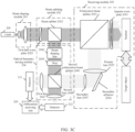
- the receiving module 203 includes a polarization beam splitter 2031, a quarter-wave plate 2032, a primary lens 2033, and a secondary lens 2035.
- the receiving module further includes an optical device, for example, a secondary reflector 2034. It should be noted that the receiving module is configured to transmit the sounding signal and receive the echo signal.
- the quarter-wave plate 2032 is disposed on a refractive exit surface of the polarization beam splitter 2031.
- the laser 200, the beam shaping module 201, the beam splitting module 202, the polarization beam splitter 2031, and the quarter-wave plate 2032 are disposed on one axis.
- the sounding signal is transmitted to the quarter-wave plate 2032 through the polarization beam splitter 2031, and is then converted into a sounding signal whose polarization state is a circular polarization state or an elliptic polarization state.
- the sounding signal is transmitted by the scanner to the target object.
- the reflected signal is reflected by the target object to obtain the echo signal.
- the echo signal is received by the transmitting module 203 through the scanner, and is converted by the quarter-wave plate 2032 into an echo signal whose polarization state is a linear polarization state.
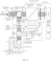
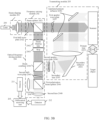
- FIG. 3D is a schematic diagram of an architecture of another laser radar optical system according to an embodiment of this application.
- the receiving module 203 shown in FIG. 3B or FIG. 3D includes optical devices such as an apertured primary reflector 2036, a first quarter-wave plate 2037, a second quarter-wave plate 2038, a primary lens 2033, and a secondary lens 2035.
- the receiving module further includes an optical device, for example, a secondary reflector 2034.
- the receiving module is configured to transmit the sounding signal and receive the echo signal.
- Fast axes of the first quarter-wave plate 2037 and the second quarter-wave plate 2038 shown in FIG. 3B and FIG. 3D and the polarization direction of the sounding signal obtained through beam splitting are at 45 degrees.
- the first quarter-wave plate 2037 is disposed between a refractive exit surface of the beam splitter 2021 and an incident surface of the apertured primary reflector 2036.
- the laser 200, the beam shaping module 201, the beam splitting module 202, the apertured primary reflector 2036, and the first quarter-wave plate 2037 are disposed on one axis.
- the second quarter-wave plate 2038 is disposed between an exit surface of the receiving module 103 and an incident surface of the optical frequency mixing module 204.
- the sounding signal is converted by the first quarter-wave plate 2037 into a signal whose polarization state is a circular polarization state or an elliptic polarization state, and is transmitted by the apertured primary reflector 2036 and the scanner to the target object.
- the sounding signal is reflected by the target object to obtain the echo signal.
- the echo signal is received by the receiving module 203 through the scanner, and is reflected by the apertured primary reflector 2036 to an optical module including the primary lens 2033, the secondary reflector 2034, and the secondary lens 2035.
- the optical module aggregates the echo signal to the second quarter-wave plate 2038.
- the second quarter-wave plate 2038 converts a polarization state of the echo signal from a circular polarization state or an elliptic polarization state to a linear polarization state. Then the echo signal is transmitted to the optical frequency mixing module 204 for optical frequency mixing with the local-frequency signal.
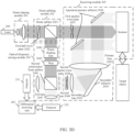
- Step S303 The optical frequency mixing module performs optical frequency mixing on the local-frequency signal and the echo signal to obtain a first beat frequency signal and a second beat frequency signal.
- information in the beat frequency signal is obtained by using a coherent light beam that is formed by using the local-frequency signal and the echo signal based on frequency mixing in free space.
- light spot sizes of the local-frequency signal and the echo signal need to be adjusted to be basically the same in the optical frequency mixing module 204, and then frequency mixing is performed on the local-frequency signal and the echo signal obtained through polarization direction conversion to obtain the first beat frequency signal and the second beat frequency signal.
- the optical frequency mixing module Because the optical frequency mixing module has a semi-transparent and semi-reflective property and performs transmission and reflection on a signal that passes, the optical frequency mixing module processes the local-frequency signal and the echo signal that pass to obtain the first beat frequency signal and the second beat frequency signal.
- the echo signal obtained through polarization direction conversion and the local-frequency signal are linearly polarized signals whose polarization directions are orthogonal.
- An included angle between a fast axis of the second half-wave plate 2045 and a polarization direction of the local-frequency signal or the echo signal is 45°.
- the local-frequency signal is shaped by the beam shaping lens 2042 and the stop 2043 into a signal whose light spot size is the same as that of the echo signal.
- the beam combiner 2044 combines the echo signal obtained through polarization state conversion and the local-frequency signal into one optical path.
- the second half-wave plate 2045 converts, into a first 45-degree polarized signal and a second (45+90)-degree polarized signal respectively, the echo signal and the local-frequency signal that are combined into one optical path.
- Mixing frequency is performed on the first 45-degree polarized signal and the second 45-degree polarized signal at the first polarization beam splitter 2046 to obtain the first beat frequency signal and the second beat frequency signal whose phase difference is 180 degrees.
- the optical frequency mixing module 204 includes a beam shaping lens 2042, a stop 2043, a second polarization beam splitter 2040, a first lens 2047, and a second lens 2048.
- the local-frequency signal is shaped by the beam shaping lens 2042 and the stop 2043 into a signal whose light spot size is the same as that of the echo signal, and a polarization direction of the local-frequency signal is 45 degrees.
- a polarization direction of the echo signal obtained through polarization state conversion is (45+90) degrees.
- the echo signal and the local-frequency signal are linearly polarized light whose polarization directions are orthogonal.
- the second polarization beam splitter 2040 performs frequency mixing on the local-frequency signal and the echo signal respectively in two paths to obtain the first beat frequency signal and the second beat frequency signal whose phase difference is 180 degrees.
- the first beat frequency signal and the second beat frequency signal obtained by the optical frequency mixing module 204 are aggregated by the first lens 2047 and the second lens 2048 to photosensitive surfaces of the detector 211 and the detector 212 respectively. Then the differential receiving unit 205 performs differential amplification on the first beat frequency signal and the second beat frequency signal received by the detector 211 and the detector 212 to obtain one beat frequency signal.
- the beat frequency signal obtained through differential amplification is output by the differential receiving unit 205 by performing differential amplification on the signals received by the detector 211 and the detector 212. With the signal output through differential amplification, noise can be greatly reduced, and a signal-to-noise ratio can be increased, thereby improving measurement precision. It should be noted that polarization states of the first 45-degree polarized signal and the second 45-degree polarized signal are linear polarization states.
- an exit surface or an incident surface of an optical lens adjacent to the wave plate may be coated with a film, or a wave plate may be bonded to the exit surface or the incident surface, to implement a function of the wave plate.
- the refractive exit surface of the polarization beam splitter 2031 may be coated with a film, or a wave plate may be bonded to the refractive exit surface, to implement a function of the quarter-wave plate 2032.
- the term “when” may be interpreted as “if”, “after”, “in response to determining”, or “in response to detecting” based on the context.
- the phrase “when it is determined that” or “if (a stated condition or event) is detected” may be interpreted as “if it is determined that", “in response to determining”, “when (a stated condition or event) is detected”, or “in response to detecting (a stated condition or event)” based on the context.
- All or some of the foregoing embodiments may be implemented by using software, hardware, firmware, or any combination thereof.
- software is used to implement the embodiments, all or a part of embodiments may be implemented in a form of a computer program product.
- the computer program product includes one or more computer instructions.
- the computer may be a general-purpose computer, a dedicated computer, a computer network, or another programmable apparatus.
- the computer instructions may be stored in a computer-readable storage medium or may be transmitted from a computer-readable storage medium to another computer-readable storage medium.
Abstract
Description
- This application relates to the radar detection field, and in particular, to a laser radar and an intelligent vehicle.
- A laser radar (LiDAR) is an optical remote sensing technology in which related information of a target is obtained by detecting a scattered light characteristic of the target. The LiDAR has high measurement precision and fine time and space resolutions, can perform functions such as mapping, tracking, and imaging recognition, and has broad application prospects in the fields of intelligent transportation, automated driving, atmospheric environment monitoring, geographical mapping, unmanned aerial vehicles, and the like. The LiDAR may be mainly classified into three types based on modulation schemes: a pulsed laser radar (Pulsed LiDAR), an amplitude modulated continuous wave laser radar (AMCW LiDAR), and a coherent laser radar (Coherent LiDAR).
- For the coherent laser radar, a linear frequency modulated laser signal is transmitted, and an echo signal formed by reflecting the laser signal by a target is received by the laser radar. The echo signal and a local-frequency signal are coherent at a front end of a detector, to generate a beat frequency signal whose frequency is a difference between instantaneous frequencies of the echo signal and the local-frequency signal. Speed information and distance information of the target may be obtained by analyzing the beat frequency signal.
- A common laser radar transmits a signal and receives a signal through an optical path of an optical fiber. Due to a limitation of a size of the optical fiber, energy of a received echo signal is limited, resulting in low detection precision of the laser radar.
- Embodiments of this application disclose a laser radar optical system, to transmit a signal through a spatial optical path, increase a reception aperture according to an actual requirement, and increase received echo signals.
- A first aspect of embodiments of this application discloses a laser radar, including: a laser, configured to generate a laser signal; a beam shaping module, configured to perform collimation on the laser signal; a beam splitting module, configured to perform beam splitting on a laser signal obtained through collimation to obtain a sounding signal and a local-frequency signal; a receiving module, configured to receive an echo signal and transmit echo information to an optical frequency mixing module, where the echo signal is a signal obtained by reflecting the sounding signal by a target object; the optical frequency mixing module, configured to perform optical frequency mixing on the local-frequency signal and the echo signal to obtain a first beat frequency signal and a second beat frequency signal, where a phase difference between the first beat frequency signal and the second beat frequency signal is 180 degrees; and a differential receiving unit, configured to differentially receive the first beat frequency signal and the second beat frequency signal, where the first beat frequency signal and the second beat frequency signal are used to determine target information of the target object.
- In the foregoing method, a coherent detection optical path is implemented by using the beam shaping module, the beam splitting module, the receiving module, and the optical frequency mixing module, so that an aperture for receiving the echo signal can be increased, an optical crosstalk problem of the echo signal can be alleviated, and therefore more energy of the echo signal can be received. Therefore, more energy of the first beat frequency signal and the second beat frequency signal can be obtained by performing frequency mixing on the local-frequency signal and the echo signal, thereby improving precision of detecting the target object by the laser radar.
- Optionally, the beam splitting module includes a beam splitter and a first half-wave plate, the first half-wave plate is disposed between the beam shaping module and the beam splitter, and the first half-wave plate is configured to adjust a polarization direction of the laser signal.
- Optionally, the target information of the target object includes at least one of a distance or a speed.
- Optionally, the receiving module includes a quarter-wave plate, a quarter-wave plate is disposed on a side, of the beam splitter, on which the sounding signal is output, a quarter-wave plate is disposed on a side, of the optical frequency mixing module, on which the echo signal is input, and the quarter-wave plate is configured to perform polarization state conversion on the echo signal and the sounding signal that pass.
- In the foregoing method, polarization states of the echo signal and the sounding signal are changed by using the quarter-wave plate, so that frequency mixing efficiency can be improved.
- Optionally, the quarter-wave plate disposed on the side, of the beam splitter, on which the sounding signal is output and the quarter-wave plate disposed on the side, of the optical frequency mixing module, on which the echo signal is input are one wave plate; or the quarter-wave plate disposed on the side, of the beam splitter, on which the sounding signal is output and the quarter-wave plate disposed on the side, of the optical frequency mixing module, on which the echo signal is input are two different wave plates.
- Optionally, the optical frequency mixing module includes a beam combiner and a polarization beam splitter, the wave plate further includes a second half-wave plate, and the polarization beam splitter includes a first polarization beam splitter. The second half-wave plate is disposed between the beam combiner and the first polarization beam splitter. The beam splitter, the beam combiner, the second half-wave plate, and the first polarization beam splitter are disposed on one axis. The beam combiner is configured to combine the echo signal for polarization state conversion and the local-frequency signal into one optical path. The second half-wave plate is configured to convert the echo signal and the local-frequency signal that are combined into one optical path into a first 45-degree polarized signal and a second 45-degree polarized signal respectively, where the first 45-degree polarized signal and the second 45-degree polarized signal are signals whose polarization directions are orthogonal. The first polarization beam splitter is configured to perform frequency mixing on the first 45-degree polarized light and the second 45-degree polarized light to obtain the first beat frequency signal and the second beat frequency signal whose phase difference is 180 degrees.
- Optionally, the polarization beam splitter includes a second polarization beam splitter. The beam splitter and the second polarization beam splitter are disposed on one axis. The second polarization beam splitter is configured to perform frequency mixing on the echo signal for polarization state conversion and the local-frequency signal that are respectively in two optical paths, to obtain the first beat frequency signal and the second beat frequency signal whose phase difference is 180 degrees. The echo signal and the local-frequency signal are signals whose polarization directions are orthogonal.
- Optionally, polarization states of the sounding signal and the local-frequency signal are linear polarization states.
- Optionally, a polarization state of a sounding signal obtained through polarization state conversion is a circular polarization state or an elliptic polarization state.
- Optionally, a polarization state of the echo signal is a circular polarization state or an elliptic polarization state, and a polarization state of an echo signal obtained through polarization state conversion is a linear polarization state.
- A second aspect of embodiments of this application discloses an intelligent vehicle, including a laser radar and a processor. The laser radar is configured to perform the functions of the laser radar in the first aspect. The processor is configured to perform intelligent driving based on the laser radar.
- In the foregoing method, the intelligent vehicle performs intelligent driving based on the laser radar, so that precision of a driving path can be improved, and a driving safety coefficient can be increased.
-
-
FIG. 1 is a functional block diagram of an intelligent vehicle according to an embodiment of this application; -
FIG. 2 is a schematic diagram of an architecture of a laser radar based on an optical path of an optical fiber according to an embodiment of this application; -
FIG. 2A is a schematic diagram of an architecture of a laser radar according to an embodiment of this application; -
FIG. 2B is a schematic diagram of a beat frequency signal generated by a triangular wave according to an embodiment of this application; -
FIG. 3 is a schematic flowchart of a beat frequency signal generation method according to an embodiment of this application; -
FIG. 3A is a schematic diagram of a structure of a laser radar according to an embodiment of this application; -
FIG. 3B is a schematic diagram of a structure of another laser radar according to an embodiment of this application; -
FIG. 3C is a schematic diagram of a structure of another laser radar according to an embodiment of this application; and -
FIG. 3D is a schematic diagram of a structure of another laser radar according to an embodiment of this application. - The following describes embodiments of this application with reference to the accompanying drawings in embodiments of this application.
- An embodiment of this application provides an
intelligent vehicle 001.FIG. 1 is a functional block diagram of an intelligent vehicle according to an embodiment of this application. In an embodiment, theintelligent vehicle 001 may be configured in a fully or partially automated driving mode. For example, theintelligent vehicle 001 may control theintelligent vehicle 001 in the automated driving mode, determine a current status of the vehicle and a surrounding environment of the vehicle through a manual operation, determine possible behavior of at least one another vehicle in the surrounding environment, determine a confidence level corresponding to a possibility of performing the possible behavior by the another vehicle, and control theintelligent vehicle 001 based on determined information. When theintelligent vehicle 001 is in the automated driving mode, theintelligent vehicle 001 may be configured to operate without interacting with a person. - The
intelligent vehicle 001 may include various subsystems, for example, atravel system 102, asensor system 104, acontrol system 106, one or moreperipheral devices 108, apower supply 110, acomputer system 112, and auser interface 116. Optionally, theintelligent vehicle 001 may include more or fewer subsystems, and each subsystem may include a plurality of elements. In addition, the subsystems and the elements of theintelligent vehicle 001 may be all interconnected in a wired or wireless manner. - The
travel system 102 may include a component that provides power for motion of theintelligent vehicle 001. In an embodiment, thetravel system 102 may include anengine 118, anenergy source 119, a transmission apparatus 120, and a wheel/tire 121. Theengine 118 may be an internal combustion engine, an electric motor, an air compression engine, or a combination of other types of engines, for example, a hybrid engine including a gasoline engine and an electric motor, or a hybrid engine including an internal combustion engine and an air compression engine. Theengine 118 converts theenergy source 119 into mechanical energy. - For example, the
energy source 119 includes gasoline, diesel, other petroleum-based fuels, propane, other compressed gas-based fuels, anhydrous alcohol, a photovoltaic module, a battery, and other power sources. Theenergy source 119 may also provide energy for another system of theintelligent vehicle 001. - The transmission apparatus 120 may transmit mechanical power from the
engine 118 to thewheel 121. The transmission apparatus 120 may include a gearbox, a differential, and a drive shaft. In an embodiment, the transmission apparatus 120 may further include another device, for example, a clutch. The drive shaft may include one or more shafts that may be coupled to one ormore wheels 121. - The
sensor system 104 may include several sensors that sense information about a surrounding environment of theintelligent vehicle 001. For example, thesensor system 104 may include a positioning system 122 (the positioning system may be a GPS system, a BeiDou system, or another positioning system), an inertial measurement unit (inertial measurement unit, IMU) 124, alaser radar 126, alaser rangefinder 128, and acamera 130. Thesensor system 104 may further include a sensor that monitors an internal system of the intelligent vehicle 001 (for example, a vehicle-mounted air quality monitor, a fuel gauge, or an oil temperature gauge). Sensor data from one or more of these sensors may be used to detect an object and corresponding features (a location, a shape, a direction, a speed, and the like) of the object. The detection and recognition are key functions for implementing a safe operation by the autonomousintelligent vehicle 001. - The positioning system 122 may be configured to estimate a geographical location of the
intelligent vehicle 001. TheIMU 124 is configured to sense a location and direction change of theintelligent vehicle 001 based on an inertial acceleration. In an embodiment, theIMU 124 may be a combination of an accelerometer and a gyroscope. For example, theIMU 124 may be configured to measure a curvature of theintelligent vehicle 001. - The
laser radar 126 may use a radio signal to sense an object in a surrounding environment of theintelligent vehicle 001. In some embodiments, thelaser radar 126 is a radar system for transmitting a sounding signal to detect characteristics, such as a location and a speed, of a target object. An operating principle of thelaser radar 126 is as follows: A sounding signal (a laser beam) is transmitted to a target object, and then coherence is implemented between a local-frequency signal and a received signal reflected from the target object (an echo signal), to generate a first beat frequency signal and a second beat frequency signal whose frequencies are a difference between instantaneous frequencies of the echo signal and the local-frequency signal. A phase difference between the first beat frequency signal and the second beat frequency signal is 180 degrees. Then a differential receiving unit performs differential amplification on the first beat frequency signal and the second beat frequency signal, and outputs signals obtained through differential amplification to a processor, and the processor processes the signals to obtain information, such as a speed and a distance, of the target object. - The
laser rangefinder 128 may use laser light to sense an object in an environment in which theintelligent vehicle 001 is located. In some embodiments, thelaser rangefinder 128 may include one or more laser sources, a laser scanner, one or more detectors, and another system component. - The
camera 130 may be configured to capture a plurality of images of a surrounding environment of theintelligent vehicle 001. Thecamera 130 may be a still camera or a video camera. - The
control system 106 controls operations of theintelligent vehicle 001 and components of theintelligent vehicle 001. Thecontrol system 106 may include various elements, including asteering system 132, athrottle 134, abraking unit 136, a sensor fusion algorithm 138, acomputer vision system 140, a path control system 142, and anobstacle avoidance system 144. - The
steering system 132 may operate to adjust an advancing direction of theintelligent vehicle 001. For example, in an embodiment, thesteering system 132 may be a steering wheel system. - The
throttle 134 is configured to control an operating speed of theengine 118, so as to control a speed of theintelligent vehicle 001. - The
braking unit 136 is configured to control theintelligent vehicle 001 to decelerate. Thebraking unit 136 may slow down thewheel 121 through friction. In another embodiment, thebraking unit 136 may convert kinetic energy of thewheel 121 into a current. Alternatively, thebraking unit 136 may reduce a rotational speed of thewheel 121 in another form, so as to control the speed of theintelligent vehicle 001. - The
computer vision system 140 may operate to process and analyze an image captured by thecamera 130, so as to recognize objects and/or features in the surrounding environment of theintelligent vehicle 001. The objects and/or the features may include a traffic signal, a road boundary, and an obstacle. Thecomputer vision system 140 may use an object recognition algorithm, a structure from motion (Structure from Motion, SFM) algorithm, video tracking, and other computer vision technologies. In some embodiments, thecomputer vision system 140 may be configured to draw a map for an environment, track an object, estimate a speed of an object, and the like. - The path control system 142 is configured to determine a travel path for the
intelligent vehicle 001. In some embodiments, the path control system 142 may determine the travel path for theintelligent vehicle 001 with reference to data from the sensor 138, the GPS 122, and one or more predetermined maps. - The
obstacle avoidance system 144 is configured to recognize, evaluate, and avoid or bypass, in another manner, a potential obstacle in the environment of theintelligent vehicle 001. - Certainly, in an example, the
control system 106 may additionally or alternatively include components other than those shown and described. Alternatively, some of the components shown above may be omitted. - The
intelligent vehicle 001 interacts with an external sensor, another vehicle, another computer system, or a user by using theperipheral device 108. Theperipheral device 108 may include awireless communication system 146, a vehicle-mounted computer 148, amicrophone 150, and/or aspeaker 152. - In some embodiments, the
peripheral device 108 provides a means for a user of theintelligent vehicle 001 to interact with theuser interface 116. For example, the vehicle-mounted computer 148 may provide information for the user of theintelligent vehicle 001. Theuser interface 116 may further operate the vehicle-mounted computer 148 to receive a user input. The vehicle-mounted computer 148 may be operated by using a touchscreen. In other cases, theperipheral device 108 may provide a means for theintelligent vehicle 001 to communicate with another device located in the vehicle. For example, themicrophone 150 may receive audio (for example, a voice command or another audio input) from the user of theintelligent vehicle 001. Similarly, thespeaker 152 may output audio to the user of theintelligent vehicle 001. - The
wireless communication system 146 may wirelessly communicate with one or more devices directly or by using a communication network. For example, thewireless communication system 146 may use 3G cellular communication such as CDMA, EVD0, or GSM/GPRS, 4G cellular communication such as LTE, or 5G cellular communication. Thewireless communication system 146 may communicate with a wireless local area network (wireless local area network, WLAN) by using Wi-Fi. In some embodiments, thewireless communication system 146 may directly communicate with a device by using an infrared link, Bluetooth, or ZigBee. Other wireless protocols, such as various vehicle communication systems, for example, thewireless communication system 146, may include one or more dedicated short range communications (dedicated short range communications, DSRC) devices, and these devices may include public and/or private data communication between vehicles and/or roadside stations. - The
power supply 110 may supply power to the components of theintelligent vehicle 001. In an embodiment, thepower supply 110 may be a rechargeable lithium-ion or lead-acid battery. One or more battery packs of such a battery may be configured as a power supply to supply power to the components of the intelligent vehicle 002. In some embodiments, thepower supply 110 and theenergy source 119 may be implemented together For example, thepower supply 110 and theenergy source 119 are implemented together in some all-electric vehicles. - Some or all functions of the
intelligent vehicle 001 are controlled by thecomputer system 112. Thecomputer system 112 may include at least oneprocessor 113. Theprocessor 113 executesinstructions 115 stored in a non-transitory computer-readable medium such as adata storage apparatus 114. Thecomputer system 112 may be alternatively a plurality of computing devices that control individual components or subsystems of theintelligent vehicle 001 in a distributed manner. - The
processor 113 may be any conventional processor such as a commercially available CPU. Alternatively, the processor may be a dedicated device such as an ASIC or another hardware-based processor. AlthoughFIG. 1 functionally shows the processor, the memory, and other elements of a computer in a same block, a person of ordinary skill in the art should understand that the processor, the computer, or the memory may actually include a plurality of processors, computers, or memories that may or may not be stored in a same physical housing. For example, the memory may be a hard disk drive or another storage medium located in a housing different from that of the computer. Therefore, a reference to the processor or the computer is understood as including a reference to a set of processors, computers, or memories that may or may not operate in parallel. Different from using a single processor to perform the steps described herein, some components, such as a steering component and a deceleration component, each may have its own processor, and the processor performs only calculation related to a component-specific function. - In various aspects described herein, the processor may be located away from the vehicle and wirelessly communicate with the vehicle. In another aspect, some of the processes described herein are performed on a processor arranged in the vehicle, and others are performed by a remote processor, including performing a necessary step to perform single manipulation.
- In some embodiments, the
memory 114 may include instructions 115 (for example, program logic), and theinstructions 115 may be executed by theprocessor 113 to perform various functions of theintelligent vehicle 001, including the functions described above. Thememory 124 may also include additional instructions, including instructions to send data to, receive data from, interact with, and/or control one or more of thetravel system 102, thesensor system 104, thecontrol system 106, and theperipheral device 108. - In addition to the
instructions 115, thememory 114 may further store data such as road map and path information, other data such as a location, direction and speed of a vehicle, and a speed and location of a target object (for example, another vehicle) around the vehicle, and other information. The information may be used by theintelligent vehicle 001 and thecomputer system 112 when theintelligent vehicle 001 operates in an autonomous mode, a semi-autonomous mode, and/or a manual mode. - The
user interface 116 is configured to provide information for or receive information from the user of theintelligent vehicle 001. Optionally, theuser interface 116 may include one or more input/output devices in a set ofperipheral devices 108, for example, thewireless communication system 146, the vehicle-mounted computer 148, themicrophone 150, and thespeaker 152. - The
computer system 112 may control a function of theintelligent vehicle 001 based on inputs received from various subsystems (for example, thetravel system 102, thesensor system 104, and the control system 106) and theuser interface 116. For example, thecomputer system 112 may control, by using an input from thecontrol system 106, thesteering unit 132 to avoid obstacles detected by thesensor system 104 and the obstacle avoidance system 244. In some embodiments, thecomputer system 112 is operable to provide control over many aspects of theintelligent vehicle 001 and the subsystems of theintelligent vehicle 001. - Optionally, one or more of the foregoing components may be mounted in separation from or associated with the
intelligent vehicle 001. For example, thedata storage apparatus 114 may be partially or completely separated from theintelligent vehicle 001. The foregoing components may be communicatively coupled together in a wired and/or wireless manner. - Optionally, the foregoing components are merely examples. In actual application, components in the foregoing modules may be added or omitted according to an actual requirement.
FIG. 1 should not be understood as a limitation on embodiments of this application. - The
intelligent vehicle 001 may be a car, a truck, a motorcycle, a bus, a boat, an airplane, a helicopter, a lawn mower, an entertainment vehicle, a playground vehicle, a construction device, a tram, a golf cart, a train, a handcart, or the like. This is not particularly limited in embodiments of this application. - It can be understood that the functional diagram of the intelligent vehicle in
FIG. 1 is only an example implementation in this embodiment of this application, and the intelligent vehicle in this embodiment of this application includes but is not limited to the foregoing structure. - Currently, a common laser radar is shown in
FIG. 2 , which is a schematic diagram of an architecture of a laser radar based on an optical path of an optical fiber. It can be learned fromFIG. 2 that the laser radar based on an optical path of an optical fiber includes a laser, a 1×2 fiber-optic coupler, a fiber-optic circulator, and a 2×1 fiber-optic coupler. A laser signal transmitted by the laser enters an optical path through coupling by an optical fiber. The laser signal is split by the 1×2 fiber-optic coupler into two parts: a sounding signal and a local-frequency signal. The sounding signal is transmitted to a target object through the fiber-optic circulator. An echo signal formed through reflection by the target object is coupled to the optical fiber by a lens, is received by the fiber-optic circulator, and then passes the 2×1 fiber-optic coupler with the local-frequency signal to generate a beat frequency signal. Then the beat frequency signal is received by a detector and then processed by a differential amplifier circuit. - Because the sounding signal needs to be transmitted through the fiber-optic circulator and the echo signal needs to be received through the fiber-optic circulator, existence of the fiber-optic circulator may cause crosstalk to the received echo signal. In addition, the echo signal needs to be coupled to the optical fiber through the lens. Due to a limitation of a size of the optical fiber, an aperture of the lens cannot be excessively large. This limits energy of the received echo signal, resulting in low precision of detection by the laser radar.
- To resolve the foregoing problems, this application proposes a laser radar.
FIG. 2A is a schematic diagram of an architecture of a laser radar according to an embodiment of this application. The laser radar includes alaser 200, abeam shaping module 201, abeam splitting module 202, a receivingmodule 203, an opticalfrequency mixing module 204, adifferential receiving unit 205, an analog-to-digital converter (analog-to-digital converter, ADC) 206, and aprocessor 207. - The laser radar in this embodiment of this application can be used in various fields such as intelligent transportation, automated driving, atmospheric environment monitoring, geographical mapping, and unmanned aerial vehicles, and can perform distance measurement, speed measurement, target tracking, imaging recognition, and other functions.
- The
laser 200 generates a laser signal. The laser signal generated by the laser may be a frequency modulated continuous wave (Frequency Modulated Continuous Wave, FMCW) signal, and a modulation waveform of a laser frequency of the laser signal may be in a sawtooth shape, or may be a triangular wave or a waveform in another form. When the laser signal generated by thelaser 200 is an FMCW signal, thelaser 200 may be a tunable laser (Tunable Laser, TL), for example, a distributed feedback laser (Distributed Feedback Laser, DFB), a laser diode (Laser diode, LD), a fiber-optic laser, or a vertical cavity surface emitting laser (Vertical Cavity Surface Emitting Laser, VCSEL). It can be understood that the laser signal may be referred to as a laser pulse, a laser beam, laser light, or another name, and these names all fall within the protection scope of embodiments of this application provided that the names have the same meaning. In this embodiment of this application, the laser signal generated by thelaser 200 is used to measure at least one of a speed or a distance of atarget object 210. - The
beam shaping module 201 is configured to perform collimation on the laser signal generated by thelaser 200. A signal obtained through collimation may meet preset optical characteristic requirements such as a light spot size, a divergence angle, and a beam waist radius. It should be noted that thebeam shaping module 201 may be a lens, to be specific, includes one or more lenses. - The
beam splitting module 202 is configured to perform beam splitting on the laser signal obtained through collimation, to obtain a sounding signal and a local-frequency signal through beam splitting. Optical characteristics, such as energy and polarization states, of the sounding signal and the local-frequency signal obtained through beam splitting are consistent, and are all consistent with optical characteristics of the laser signal generated by thelaser 200. - The receiving
module 203 includes a scanner 203A, and the scanner 203A is also referred to as a 2D scanner. The receivingmodule 203 is configured to convert a polarization state of the sounding signal, and the scanner 203A transmits the sounding signal based on a specific angle. After the transmit signal is transmitted, the transmit signal is reflected by thetarget object 210 to form an echo signal. In this case, the scanner 203A is further configured to receive the echo signal, and the receivingmodule 203 is further configured to convert a polarization state of the received echo signal, and then aggregate the echo signal to the optical frequency mixing module. A module used for transmission and a module used for reception in thereceiving module 203 may be modules independent of each other. The receivingmodule 203 usually includes a telescopic optical system, and the telescopic optical system may include at least one of the following telescopic optical systems: a Kepler type, a Galileo type, a Newton type, and a Cassegrain type. - The optical
frequency mixing module 204 is configured to perform frequency mixing on the echo signal received by the receivingmodule 203 and the local-frequency signal obtained through splitting by thebeam splitting module 202, to obtain a first beat frequency signal and a second beat frequency signal. The optical frequency mixing module has a semi-transparent and semi-reflective property, to be specific, performs reflection and refraction on a received signal to form two beams of signals. The first beat frequency signal and the second beat frequency signal are used to determine at least one of a distance or a speed of the target object. Beat frequency signals obtained by the opticalfrequency mixing module 204 by performing frequency mixing includes the first beat frequency signal and the second beat frequency signal, and a phase difference between the first beat frequency signal and the second beat frequency signal is 180 degrees. It should be noted that the beat frequency signal is a signal whose frequency is a difference between instantaneous frequencies of the local-frequency signal and the echo signal. The beat frequency signal may also be referred to as a beat wave signal, a differential frequency signal, or the like. A name of the beat frequency signal is not limited in this embodiment of this application. - The laser radar further includes a
detector 211 and adetector 212. The first beat frequency signal generated by the opticalfrequency mixing module 204 is received by a photosensitive surface of thedetector 211, and the second beat frequency signal received by the opticalfrequency mixing module 204 is collected by a photosensitive surface of thedetector 212. - The
differential receiving unit 205 is configured to differentially receive the first beat frequency signal and the second beat frequency signal that are received by thedetector 211 and thedetector 212 to obtain one beat frequency signal. With the signal obtained through differential reception, noise can be greatly reduced, and a signal-to-noise ratio can be increased, thereby improving measurement precision of a radar detection system. - The analog-to-
digital converter ADC 206 is configured to sample a beat frequency signal. The sampling is essentially a process of converting an analog signal into a digital signal. - For the
processor 207, the processor may include a device with a computing capability, for example, a digital signal processor (Digital signal processor, DSP), a central processing unit (CPU), an accelerated processing unit (APU), a graphics processing unit (GPU), a microprocessor, or a microcontroller. The DSP is used as an example for description in the accompany drawing. The processor is configured to process the sampled beat frequency signal to obtain information, such as a speed and a distance, of thetarget object 210. - In this embodiment of this application, the
target object 210 is also referred to as a reflector, and thetarget object 210 may be any object in a scanning direction of the scanner, for example, may be a person, a mountain, a vehicle, a tree, or a bridge.FIG. 1 shows a vehicle as an example. - In this embodiment of this application, the operation of processing the sampled beat frequency signal to obtain the information, such as the speed and the distance, of the
target object 210 may be performed by one ormore processors 207, for example, performed by one or more DSPs, or certainly, performed by one ormore processors 207 in conjunction with another device, for example, jointly performed by one DSP in conjunction with one or more central processing units CPUs. When theprocessor 207 processes the beat frequency signal, this may be specifically implemented by invoking a computer program stored in a computer-readable storage medium. The computer-readable storage medium includes but is not limited to a random access memory (random access memory, RAM), a read-only memory (read-only memory, ROM), an erasable programmable read-only memory (erasable programmable read only memory, EPROM), and a compact disc read-only memory (compact disc read-only memory, CD-ROM), and may be configured in theprocessor 207, or may be independent of theprocessor 207. - In this embodiment of this application, some of the aforementioned devices may be a single device or a plurality of devices. For example, there may be one or
more lasers 200. When there is onelaser 200, the onelaser 200 may alternately transmit a laser signal with a positive slope and a laser signal with a negative slope in time domain. When there are twolasers 200, one laser transmits a laser signal with a positive slope, the other laser transmits a laser signal with a negative slope, and the twolasers 200 may transmit laser signals synchronously. - As shown in
FIG. 2B , for example, the modulation waveform of the frequency of the laser signal is triangular-wave linear frequency modulation. Frequency mixing is performed on the echo signal and the local-frequency signal after a time of flight. The time of flight is a time from a moment at which the sounding signal obtained through splitting from the laser signal is transmitted to a moment at which the echo signal is returned. The beat frequency signal generated by the echo signal and the local-frequency signal after the time of flight is constant within a specific time. The beat frequency signal is a beat frequency signal obtained by the differential receiving unit by differentially receiving the first beat frequency signal and the second beat frequency signal. The time is a beat frequency time. The beat frequency signal can accurately reflect the distance and speed information of the target object. The beat frequency signal needs to include a beat frequency f1 corresponding to a positive slope and a beat frequency f2 corresponding to a negative slope. A spectrum fspeed related to the speed of the target object may be expressed as fspeed=(f1-f2)/2. A frequency fdistance related to the distance of the target object may be expressed as fdistance=(f1+f2)/2. After fspeed and fdistance are obtained, the distance of the target object (from the laser radar) and the moving speed of the target object may be calculated. -
FIG. 3 is a schematic flowchart of a beat frequency signal generation method according to an embodiment of this application. The process may be implemented based on the laser radar shown inFIG. 2A . The method includes but is not limited to the following steps. - Step S300: The beam shaping module performs collimation on a laser signal generated by the laser.
- Specifically, light spot energy of the laser signal generated by the
laser 200 in the laser radar optical system is usually non-uniformly distributed in space. Generally, light spot energy is higher in the middle and lower at edges. Typical distribution of light spot energy in space is Gaussian distribution. A beam of the laser signal has different beam waist locations and sizes in a fast-axis direction and a slow-axis direction, so that the laser signal forms a beam in the fast-axis direction and an astigmatic beam in the slow-axis direction. The beam in the fast-axis direction and the beam in the slow-axis direction have different divergence angles. The beam in the fast-axis direction has a larger divergence angle, and the beam in the slow-axis direction has a smaller divergence angle. As a result, the beam of the laser signal transmitted by thelaser 200 is asymmetrical, and beam quality is poor. To ensure that the laser radar optical system in this embodiment of this application can have high accuracy during use to achieve sensitive information collection, and to achieve uniform distribution of light spot energy and high beam quality for the laser signal, the beam of the laser signal in the fast-axis direction needs to be collimated and the beam in the slow-axis direction needs to be homogenized by using thebeam shaping module 201. - With reference to the
beam shaping module 201 shown inFIG. 3A , thebeam shaping module 201 may include one or more lenses. In this embodiment of this application, descriptions are provided by using a beam shaping module including two lenses as an example. In actual application, a corresponding lens may be selected according to an actual requirement (for example, a specific requirement such as a light spot size, a divergence angle, and a beam waist radius). - Step S301: The beam splitting module performs beam splitting on a laser signal obtained through collimation, to obtain a sounding signal and a local-frequency signal.
- Specifically, in this embodiment of this application, the laser signal generated by the
laser 200 in the laser radar optical system is a frequency modulated continuous wave laser signal, and information carried in the frequency modulated continuous wave laser signal is mainly frequency information. A beat frequency signal is obtained through coherence between the local-frequency signal and an echo signal. At least one of a distance or a speed of the target object is calculated by using the beat frequency signal. Therefore, beam splitting needs to be performed, by using thebeam splitting module 202, on the laser signal obtained through collimation, to obtain the sounding signal and the local-frequency signal. The local-frequency signal and the sounding signal are linearly polarized laser signals with a same polarization direction. - Optionally, as shown in
FIG. 3A andFIG. 3B , thebeam splitting module 202 includes an optional first half-wave plate 2022 and abeam splitter 2021. The laser signal obtained through processing by thebeam shaping module 201 is a linearly polarized laser signal. The optional first half-wave plate 2022 adjusts a polarization direction of the linearly polarized laser signal, and thebeam splitter 2021 in thebeam splitting module 202 performs beam splitting on the linearly polarized laser signal to obtain the local-frequency signal and the sounding signal. - Optionally, as shown in
FIG. 3C andFIG. 3D , thebeam splitting module 202 includes a first half-wave plate 2022 and abeam splitter 2041. An angle of a laser signal passing through the first half-wave plate may be adjusted by adjusting an included angle between a fast axis of the first half-wave plate 2022 and a linear polarization direction of the laser signal. InFIG. 3C andFIG. 3D provided in this embodiment of this application, the first half-wave plate 2022 is configured to adjust the linearly polarized laser signal into a signal whose polarization direction is 45 degrees. Therefore, polarization directions of the local-frequency signal and the echo signal that are obtained through beam splitting by thebeam splitter 2021 are also 45 degrees. - The
beam splitter 2021 may be a polarization beam splitter, a non-polarization beam splitter, a half-silvered prism, or a flat-plate splitter. Thebeam splitter 2021 shown inFIG. 3A is an example provided in this embodiment of this application. The laser signal is split into two or more beams through reflection and refraction by thebeam splitter 2021. As shown inFIG. 3A , in this embodiment of this application, a signal obtained through reflection by thebeam splitter 2021 is the local-frequency signal, and a signal obtained through refraction by thebeam splitter 2021 is the sounding signal. - It should be noted that, if the laser signal transmitted by the laser is a linearly polarized signal, the laser signal undergoes beam shaping by the optical shaping module and then undergoes beam splitting by the beam splitting module; or if the laser signal transmitted by the laser is not a linearly polarized signal, the laser signal needs to be converted into a linearly polarized signal before the
beam splitting module 202. A specific conversion manner is disposing a wave plate (not specifically shown in the figure in this embodiment of this application) before thebeam splitting module 202. The wave plate may be disposed between thebeam shaping module 201 and thebeam splitting module 102, or the wave plate may be disposed between thelaser 200 and thebeam shaping module 201. A quantity of wave plates and a category of the wave plate may be selected based on an actual situation. This is not limited in this embodiment of this application. - Step S302: The receiving module is configured to receive the echo signal and transmit the echo signal to the optical frequency mixing module.
- Specifically, in this embodiment of this application, because a sounding signal in a circular polarization state or an elliptic polarization state has higher stability, a polarization state of a sounding signal transmitted by the receiving
module 203 to the target object is a circular polarization state or an elliptic polarization state. A polarization state of the laser signal obtained by transmitting, by thebeam shaping module 201, the laser signal generated by thelaser 200 is a linear polarization state. Therefore, a polarization state of the sounding signal obtained through beam splitting by thebeam splitter 2021 is also a linear polarization state. Therefore, a quarter-wave plate (namely, a 1/4-wave plate) needs to be disposed on a side, of thebeam splitter 2021, on which the sounding signal is output. The quarter-wave plate is configured to convert the polarization state of the sounding signal from the linear polarization state into a circular polarization state. The receivingmodule 203 receives the echo signal that is obtained by transmitting the sounding signal by the target object, and aggregates the echo signal to the opticalfrequency mixing module 204 for frequency mixing with the local-frequency signal. To improve frequency mixing efficiency, before frequency mixing is performed on the echo signal and the local-frequency signal, a quarter-wave plate needs to be disposed on a side, of the optical frequency mixing module, on which the echo signal is input. The quarter-wave plate is configured to convert a polarization state of the echo signal from a circular polarization state into a linear polarization state. - Optionally, the quarter-wave plate disposed on the side, of the
beam splitter 2021, on which the sounding signal is output and the quarter-wave plate disposed on the side, of the optical frequency mixing module, on which the echo signal is input are one wave plate. As shown inFIG. 3A orFIG. 3C , the receivingmodule 203 includes apolarization beam splitter 2031, a quarter-wave plate 2032, aprimary lens 2033, and asecondary lens 2035. Optionally, the receiving module further includes an optical device, for example, asecondary reflector 2034. It should be noted that the receiving module is configured to transmit the sounding signal and receive the echo signal. The quarter-wave plate 2032 is disposed on a refractive exit surface of thepolarization beam splitter 2031. Thelaser 200, thebeam shaping module 201, thebeam splitting module 202, thepolarization beam splitter 2031, and the quarter-wave plate 2032 are disposed on one axis. The sounding signal is transmitted to the quarter-wave plate 2032 through thepolarization beam splitter 2031, and is then converted into a sounding signal whose polarization state is a circular polarization state or an elliptic polarization state. The sounding signal is transmitted by the scanner to the target object. The reflected signal is reflected by the target object to obtain the echo signal. The echo signal is received by the transmittingmodule 203 through the scanner, and is converted by the quarter-wave plate 2032 into an echo signal whose polarization state is a linear polarization state. The echo signal is refracted by thepolarization beam splitter 2031 to an optical module including theprimary lens 2033, thesecondary reflector 2034, and thesecondary lens 2035. The optical module aggregates the echo signal to the opticalfrequency mixing module 204 for optical frequency mixing with the local-frequency signal. - Optionally, the quarter-wave plate disposed on the side, of the
beam splitter 2021, on which the sounding signal is output and the quarter-wave plate disposed on the side, of the optical frequency mixing module, on which the echo signal is input are two different wave plates. Refer toFIG. 3B orFIG. 3D. FIG. 3D is a schematic diagram of an architecture of another laser radar optical system according to an embodiment of this application. The receivingmodule 203 shown inFIG. 3B orFIG. 3D includes optical devices such as an aperturedprimary reflector 2036, a first quarter-wave plate 2037, a second quarter-wave plate 2038, aprimary lens 2033, and asecondary lens 2035. Optionally, the receiving module further includes an optical device, for example, asecondary reflector 2034. It should be noted that the receiving module is configured to transmit the sounding signal and receive the echo signal. Fast axes of the first quarter-wave plate 2037 and the second quarter-wave plate 2038 shown inFIG. 3B andFIG. 3D and the polarization direction of the sounding signal obtained through beam splitting are at 45 degrees. The first quarter-wave plate 2037 is disposed between a refractive exit surface of thebeam splitter 2021 and an incident surface of the aperturedprimary reflector 2036. Thelaser 200, thebeam shaping module 201, thebeam splitting module 202, the aperturedprimary reflector 2036, and the first quarter-wave plate 2037 are disposed on one axis. The second quarter-wave plate 2038 is disposed between an exit surface of the receiving module 103 and an incident surface of the opticalfrequency mixing module 204. The sounding signal is converted by the first quarter-wave plate 2037 into a signal whose polarization state is a circular polarization state or an elliptic polarization state, and is transmitted by the aperturedprimary reflector 2036 and the scanner to the target object. The sounding signal is reflected by the target object to obtain the echo signal. The echo signal is received by the receivingmodule 203 through the scanner, and is reflected by the aperturedprimary reflector 2036 to an optical module including theprimary lens 2033, thesecondary reflector 2034, and thesecondary lens 2035. The optical module aggregates the echo signal to the second quarter-wave plate 2038. The second quarter-wave plate 2038 converts a polarization state of the echo signal from a circular polarization state or an elliptic polarization state to a linear polarization state. Then the echo signal is transmitted to the opticalfrequency mixing module 204 for optical frequency mixing with the local-frequency signal. - Step S303: The optical frequency mixing module performs optical frequency mixing on the local-frequency signal and the echo signal to obtain a first beat frequency signal and a second beat frequency signal.
- Specifically, in this embodiment of this application, information in the beat frequency signal is obtained by using a coherent light beam that is formed by using the local-frequency signal and the echo signal based on frequency mixing in free space. To ensure full frequency mixing on the local-frequency signal and the echo signal, light spot sizes of the local-frequency signal and the echo signal need to be adjusted to be basically the same in the optical
frequency mixing module 204, and then frequency mixing is performed on the local-frequency signal and the echo signal obtained through polarization direction conversion to obtain the first beat frequency signal and the second beat frequency signal. Because the optical frequency mixing module has a semi-transparent and semi-reflective property and performs transmission and reflection on a signal that passes, the optical frequency mixing module processes the local-frequency signal and the echo signal that pass to obtain the first beat frequency signal and the second beat frequency signal. The echo signal obtained through polarization direction conversion and the local-frequency signal are linearly polarized signals whose polarization directions are orthogonal. - Optionally, as shown in
FIG. 3A orFIG. 3B , the opticalfrequency mixing module 204 includes abeam shaping lens 2042, astop 2043, abeam combiner 2044, a second half-wave plate 2045, a firstpolarization beam splitter 2046, afirst lens 2047, and asecond lens 2048. Thebeam splitter 2021, thebeam combiner 2044, the second half-wave plate 2045, and the firstpolarization beam splitter 2046 are disposed on one axis. The second half-wave plate 2045 is disposed between thebeam combiner 2044 and the firstpolarization beam splitter 2046. Thebeam combiner 2044 is configured to perform beam combination on the local-frequency signal and the echo signal. An included angle between a fast axis of the second half-wave plate 2045 and a polarization direction of the local-frequency signal or the echo signal is 45°. The local-frequency signal is shaped by thebeam shaping lens 2042 and thestop 2043 into a signal whose light spot size is the same as that of the echo signal. Thebeam combiner 2044 combines the echo signal obtained through polarization state conversion and the local-frequency signal into one optical path. Then the second half-wave plate 2045 converts, into a first 45-degree polarized signal and a second (45+90)-degree polarized signal respectively, the echo signal and the local-frequency signal that are combined into one optical path. Mixing frequency is performed on the first 45-degree polarized signal and the second 45-degree polarized signal at the firstpolarization beam splitter 2046 to obtain the first beat frequency signal and the second beat frequency signal whose phase difference is 180 degrees. - Optionally, as shown in
FIG. 3C andFIG. 3D , the opticalfrequency mixing module 204 includes abeam shaping lens 2042, astop 2043, a secondpolarization beam splitter 2040, afirst lens 2047, and asecond lens 2048. The local-frequency signal is shaped by thebeam shaping lens 2042 and thestop 2043 into a signal whose light spot size is the same as that of the echo signal, and a polarization direction of the local-frequency signal is 45 degrees. A polarization direction of the echo signal obtained through polarization state conversion is (45+90) degrees. The echo signal and the local-frequency signal are linearly polarized light whose polarization directions are orthogonal. The secondpolarization beam splitter 2040 performs frequency mixing on the local-frequency signal and the echo signal respectively in two paths to obtain the first beat frequency signal and the second beat frequency signal whose phase difference is 180 degrees. - The first beat frequency signal and the second beat frequency signal obtained by the optical
frequency mixing module 204 are aggregated by thefirst lens 2047 and thesecond lens 2048 to photosensitive surfaces of thedetector 211 and thedetector 212 respectively. Then thedifferential receiving unit 205 performs differential amplification on the first beat frequency signal and the second beat frequency signal received by thedetector 211 and thedetector 212 to obtain one beat frequency signal. The beat frequency signal obtained through differential amplification is output by thedifferential receiving unit 205 by performing differential amplification on the signals received by thedetector 211 and thedetector 212. With the signal output through differential amplification, noise can be greatly reduced, and a signal-to-noise ratio can be increased, thereby improving measurement precision. It should be noted that polarization states of the first 45-degree polarized signal and the second 45-degree polarized signal are linear polarization states. - It should be noted that, for the wave plate mentioned in this embodiment of this application, including the quarter-wave plate, the first quarter-wave plate, the second quarter-wave plate, the first half-wave plate, and the second half-wave plate, an exit surface or an incident surface of an optical lens adjacent to the wave plate may be coated with a film, or a wave plate may be bonded to the exit surface or the incident surface, to implement a function of the wave plate. For example, for the quarter-
wave plate 2032 shown inFIG. 3A , the refractive exit surface of thepolarization beam splitter 2031 may be coated with a film, or a wave plate may be bonded to the refractive exit surface, to implement a function of the quarter-wave plate 2032. Likewise, for the second half-wave plate 2045, a refractive incident surface of the first polarization beam splitter may be coated with a film, or a wave plate may be bonded to the refractive incident surface, to implement a function of the second half-wave plate 2045. - In the method shown in
FIG. 3 , a coherent detection and receiving optical path is implemented by a spatial optical path formed by optical modules such as a wave plate, a beam splitter, and a polarization beam splitter, thereby increasing an aperture for receiving an echo signal, so that more energy of the echo signal can be received, and precision of detecting a target object by a radar detection system is improved. An optical module, for example, a polarization beam splitter or an apertured primary reflector, in a transmitting/receiving module receives and detects a signal, so that interference caused by optical crosstalk to a received echo signal can be avoided. Polarization states of a sounding signal and an echo signal are converted, so that efficiency of optical frequency mixing can be improved. - As used in the foregoing embodiments, the term "when" may be interpreted as "if", "after", "in response to determining", or "in response to detecting" based on the context. Similarly, the phrase "when it is determined that" or "if (a stated condition or event) is detected" may be interpreted as "if it is determined that", "in response to determining", "when (a stated condition or event) is detected", or "in response to detecting (a stated condition or event)" based on the context.
- All or some of the foregoing embodiments may be implemented by using software, hardware, firmware, or any combination thereof. When software is used to implement the embodiments, all or a part of embodiments may be implemented in a form of a computer program product. The computer program product includes one or more computer instructions. When the computer program instructions are loaded and executed on the computer, the procedures or functions according to the embodiments of this application are all or partially generated. The computer may be a general-purpose computer, a dedicated computer, a computer network, or another programmable apparatus. The computer instructions may be stored in a computer-readable storage medium or may be transmitted from a computer-readable storage medium to another computer-readable storage medium. For example, the computer instructions may be transmitted from a website, computer, server, or data center to another website, computer, server, or data center in a wired (for example, a coaxial cable, an optical fiber, or a digital subscriber line) or wireless (for example, infrared, radio, or microwave) manner. The computer-readable storage medium may be any usable medium accessible by the computer, or a data storage device, for example, a server or a data center, integrating one or more usable media. The usable medium may be a magnetic medium (for example, a floppy disk, a hard disk, or a magnetic tape), an optical medium (for example, a DVD), a semiconductor medium (for example, a solid-state drive), or the like.
- Persons of ordinary skill in the art may understand that all or some of the procedures of the methods in embodiments may be implemented by a computer program instructing related hardware. The program may be stored in the computer-readable storage medium. When the program is executed, the procedures in the method embodiments may be included. The foregoing storage medium includes any medium that can store program code, such as a ROM, a random access memory RAM, a magnetic disk, or an optical disc.
Claims (11)
- A laser radar, comprising:a laser, configured to generate a laser signal;a beam shaping module, configured to perform collimation on the laser signal;a beam splitting module, configured to perform beam splitting on a laser signal obtained through collimation to obtain a sounding signal and a local-frequency signal;a receiving module, configured to receive an echo signal and transmit the echo signal to an optical frequency mixing module, wherein the echo signal is a reflected signal formed after the sounding signal irradiates a target object;the optical mixing module, configured to perform optical frequency mixing on the local-frequency signal and the echo signal to obtain a first beat frequency signal and a second beat frequency signal, wherein a phase difference between the first beat frequency signal and the second beat frequency signal is 180 degrees; anda differential receiving unit, configured to differentially receive the first beat frequency signal and the second beat frequency signal, wherein the first beat frequency signal and the second beat frequency signal are used to determine target information of the target object.
- The radar according to claim 1, wherein the beam splitting module comprises a beam splitter and a first half-wave plate, the first half-wave plate is disposed between the beam shaping module and the beam splitter, and the first half-wave plate is configured to adjust a polarization direction of the laser signal.
- The radar according to claim 1, wherein the receiving module comprises a quarter-wave plate, a quarter-wave plate is disposed on a side, of the beam splitting module, on which the sounding signal is output, a quarter-wave plate is disposed on a side, of the optical frequency mixing module, on which the echo signal is input, and the quarter-wave plate is configured to perform polarization state conversion on the echo signal and the sounding signal that pass.
- The radar according to claim 3, whereinthe quarter-wave plate disposed on the side, of the beam splitting module, on which the sounding signal is output and the quarter-wave plate disposed on the side, of the optical frequency mixing module, on which the echo signal is input are one wave plate; orthe quarter-wave plate disposed on the side, of the beam splitting module, on which the sounding signal is output and the quarter-wave plate disposed on the side, of the optical frequency mixing module, on which the echo signal is input are two different wave plates.
- The radar according to claim 4, wherein the optical frequency mixing module comprises a beam combiner, a first polarization beam splitter, and a second half-wave plate, the second half-wave plate is disposed between the beam combiner and the first polarization beam splitter, and the beam splitter, the beam combiner, the second half-wave plate, and the first polarization beam splitter are disposed on one axis;the beam combiner is configured to combine the echo signal for polarization state conversion and the local-frequency signal into one optical path;the second half-wave plate is configured to convert the echo signal and the local-frequency signal that are combined into one optical path into a first 45-degree polarized signal and a second 45-degree polarized signal respectively, wherein the first 45-degree polarized signal and the second 45-degree polarized signal are signals whose polarization directions are orthogonal; andthe first polarization beam splitter is configured to perform frequency mixing on the first 45-degree polarized light and the second 45-degree polarized light to obtain the first beat frequency signal and the second beat frequency signal.
- The radar according to claim 4, wherein the optical mixing module comprises a second polarization beam splitter, and the beam splitter and the second polarization beam splitter are disposed on one axis; and
the second polarization beam splitter is configured to perform frequency mixing on the echo signal for polarization state conversion and the local-frequency signal that are respectively in two optical paths, to obtain the first beat frequency signal and the second beat frequency signal. - The radar according to any one of claims 1 to 6, wherein polarization states of the sounding signal and the local-frequency signal are linear polarization states.
- The radar according to claim 7, wherein a polarization state of a sounding signal obtained through polarization state conversion is a circular polarization state or an elliptical polarization state.
- The radar according to claim 7, wherein a polarization state of the echo signal is a circular polarization state or an elliptical polarization state, and a polarization state of the echo signal obtained through polarization state conversion is a linear polarization state.
- The radar according to any one of claims 1 to 9, wherein the target information comprises at least one of a distance or a speed.
- An intelligent vehicle, comprising a laser radar and a processor, wherein the laser radar is configured to perform functions of the laser radar according to any one of claims 1 to 10, and the processor is configured to perform intelligent driving based on the laser radar.
Applications Claiming Priority (1)
| Application Number | Priority Date | Filing Date | Title |
|---|---|---|---|
| PCT/CN2020/105930 WO2022021237A1 (en) | 2020-07-30 | 2020-07-30 | Laser radar and smart vehicle |
Publications (2)
| Publication Number | Publication Date |
|---|---|
| EP4187283A1 true EP4187283A1 (en) | 2023-05-31 |
| EP4187283A4 EP4187283A4 (en) | 2023-08-16 |
Family
ID=75291142
Family Applications (1)
| Application Number | Title | Priority Date | Filing Date |
|---|---|---|---|
| EP20947111.9A Pending EP4187283A4 (en) | 2020-07-30 | 2020-07-30 | Laser radar and smart vehicle |
Country Status (4)
| Country | Link |
|---|---|
| US (1) | US20230176215A1 (en) |
| EP (1) | EP4187283A4 (en) |
| CN (2) | CN114814882A (en) |
| WO (1) | WO2022021237A1 (en) |
Families Citing this family (7)
| Publication number | Priority date | Publication date | Assignee | Title |
|---|---|---|---|---|
| CN115248437A (en) * | 2021-04-26 | 2022-10-28 | 华为技术有限公司 | Laser radar |
| CN113721225A (en) * | 2021-08-31 | 2021-11-30 | 深圳市镭神智能系统有限公司 | Frequency modulation continuous wave laser radar |
| CN114938662B (en) * | 2021-10-13 | 2023-04-04 | 深圳市速腾聚创科技有限公司 | Laser radar and control method of laser radar |
| WO2023065149A1 (en) * | 2021-10-20 | 2023-04-27 | 深圳市速腾聚创科技有限公司 | Laser radar and laser radar control method |
| WO2023065327A1 (en) * | 2021-10-22 | 2023-04-27 | 华为技术有限公司 | Detection system and terminal device |
| CN115840215B (en) * | 2023-02-13 | 2023-05-12 | 宁波飞芯电子科技有限公司 | Detection method and detection device |
| CN117647793A (en) * | 2023-08-14 | 2024-03-05 | 深圳市速腾聚创科技有限公司 | Laser radar and mobile device |
Family Cites Families (23)
| Publication number | Priority date | Publication date | Assignee | Title |
|---|---|---|---|---|
| US8242428B2 (en) * | 2007-12-06 | 2012-08-14 | The United States Of America As Represented By The Secretary Of The Army | Method and system for lidar using spatial information from a light source in combination with nonspatial information influenced by the subject to derive an image |
| USH2130H1 (en) * | 2003-11-03 | 2005-11-01 | The United States Of America As Represented By The Secretary Of The Air Force | Laser-difference-frequency discriminator |
| EP3624086A1 (en) * | 2007-01-25 | 2020-03-18 | Magna Electronics Inc. | Radar sensing system for vehicle |
| CN101256233B (en) * | 2008-03-05 | 2010-12-08 | 中国科学院上海光学精密机械研究所 | Bidirectional loop transmitting-receiving telescope for synthesis bore diameter laser imaging radar |
| CN101825712A (en) * | 2009-12-24 | 2010-09-08 | 哈尔滨工业大学 | 2 mu m all-fiber coherent laser Doppler wind finding radar system |
| CN102004255B (en) * | 2010-09-17 | 2012-07-04 | 中国科学院上海技术物理研究所 | Chirp amplitude laser infrared radar distance-Doppler zero-difference detection system |
| KR20130106408A (en) * | 2010-10-25 | 2013-09-27 | 가부시키가이샤 니콘 | Apparatus, optical assembly, method for inspection or measurement of an object and method for manufacturing a structure |
| CN102495411B (en) * | 2011-10-18 | 2013-05-29 | 中国科学院上海技术物理研究所 | Submillimeter-level linear tuning laser ranging system and signal processing method |
| GB2499616B (en) * | 2012-02-22 | 2017-03-22 | Iti Scotland Ltd | Heterodyne detection system and method |
| CN103529650B (en) * | 2012-07-02 | 2016-01-20 | 上海微电子装备有限公司 | A kind of height measuring device and measuring method thereof |
| CN105589074A (en) * | 2015-11-27 | 2016-05-18 | 中国人民解放军国防科学技术大学 | Multi-wavelength interference real-time absolute distance measurement device on the basis of femtosecond optical comb synchronization frequency locking |
| US9909927B1 (en) * | 2016-06-22 | 2018-03-06 | The United States Of America As Represented By The Secretary Of The Navy | Optical attenuation coefficient meter |
| CN106289049B (en) * | 2016-07-21 | 2019-04-16 | 哈尔滨工业大学 | Quantum interference measuring device and method based on Squeezed Vacuum injection |
| CN106680831B (en) * | 2017-01-20 | 2019-02-26 | 中国科学院上海光学精密机械研究所 | Laser is actively concerned with balance detection polarization analysis instrument |
| CN107193015B (en) * | 2017-05-09 | 2020-06-02 | 盐城师范学院 | Ultraviolet three-frequency high spectral resolution laser radar system based on F-P etalon and detection method thereof |
| SG11202002406TA (en) * | 2017-09-18 | 2020-04-29 | Advanced Micro Foundry Pte Ltd | Optical phase array, methods of forming and operating the same |
| CN109696682A (en) * | 2017-10-23 | 2019-04-30 | 华为技术有限公司 | Optical sensing module and terminal device |
| CN107894587B (en) * | 2017-12-04 | 2021-07-06 | 电子科技大学 | Pulse laser homodyne coherent detection device based on optical phase lock |
| CN109188453A (en) * | 2018-09-11 | 2019-01-11 | 哈尔滨工业大学 | Dynamic frequency scanning interfeerometry ranging system and distance measuring method based on locking phase gamma correction |
| CN109188454A (en) * | 2018-09-11 | 2019-01-11 | 哈尔滨工业大学 | Dynamic frequency scanning interfeerometry ranging system and method based on digital servo-control gamma correction |
| CN111049585B (en) * | 2018-10-13 | 2022-06-14 | 华为技术有限公司 | Optical transceiver and optical coherent receiving system |
| US11709240B2 (en) * | 2018-10-18 | 2023-07-25 | Aeva, Inc. | Descan compensation in scanning LIDAR |
| CN110244281B (en) * | 2019-07-19 | 2021-07-23 | 北京一径科技有限公司 | Laser radar system |
-
2020
- 2020-07-30 CN CN202210292408.5A patent/CN114814882A/en active Pending
- 2020-07-30 EP EP20947111.9A patent/EP4187283A4/en active Pending
- 2020-07-30 CN CN202080004707.3A patent/CN112639529B/en active Active
- 2020-07-30 WO PCT/CN2020/105930 patent/WO2022021237A1/en unknown
-
2023
- 2023-01-30 US US18/161,665 patent/US20230176215A1/en active Pending
Also Published As
| Publication number | Publication date |
|---|---|
| EP4187283A4 (en) | 2023-08-16 |
| CN112639529B (en) | 2022-03-29 |
| WO2022021237A1 (en) | 2022-02-03 |
| CN114814882A (en) | 2022-07-29 |
| US20230176215A1 (en) | 2023-06-08 |
| CN112639529A (en) | 2021-04-09 |
Similar Documents
| Publication | Publication Date | Title |
|---|---|---|
| EP4187283A1 (en) | Laser radar and smart vehicle | |
| US11945467B2 (en) | Identification of proxy calibration targets for a fleet of vehicles | |
| US20220244395A1 (en) | Calibration and Localization of a Light Detection and Ranging (Lidar) Device Using a Previously Calibrated and Localized Lidar Device | |
| WO2022099243A1 (en) | Radar interference reduction techniques for autonomous vehicles | |
| US11747453B1 (en) | Calibration system for light detection and ranging (lidar) devices | |
| US11860730B2 (en) | Low-overhead, bidirectional error checking for a serial peripheral interface | |
| WO2020154903A1 (en) | Method and device for determining elevation, and radar | |
| WO2021243529A1 (en) | Method and apparatus for estimating angle of arrival aoa | |
| CN114862931A (en) | Depth distance determination method and device, vehicle, storage medium and chip | |
| US20220011414A1 (en) | Ranging method and apparatus based on detection signal | |
| US20220334244A1 (en) | Radar ranging method and device, radar and in-vehicle system | |
| WO2020164121A1 (en) | Radar, and gain control method | |
| US20230019007A1 (en) | Beat Frequency Signal Processing Method and Apparatus | |
| US11822377B2 (en) | Timebase synchronization using pulsed signal injection | |
| WO2024055252A1 (en) | Data fusion method and apparatus, and intelligent driving device | |
| US20230194677A1 (en) | Multi-Chip Daisychain for Output Aggregation | |
| CN115179930B (en) | Vehicle control method and device, vehicle and readable storage medium | |
| US20230194676A1 (en) | Two-Step Return Calibration for Lidar Cross-Talk Mitigation | |
| US20230184910A1 (en) | Lower Power Linearization of Lidar Signals | |
| US20230358868A1 (en) | Mitigating Crosstalk from High-Intensity Returns in a Light Detection and Ranging (Lidar) Device | |
| WO2022178667A1 (en) | Lidar system, adjustment method, and related device | |
| EP4296132A1 (en) | Vehicle control method and apparatus, vehicle, non-transitory storage medium and chip | |
| WO2024058882A1 (en) | Light detection and ranging (lidar) sensor system including bistatic transceiver | |
| CN114640152A (en) | Antenna on charger infrastructure |
Legal Events
| Date | Code | Title | Description |
|---|---|---|---|
| STAA | Information on the status of an ep patent application or granted ep patent |
Free format text: STATUS: THE INTERNATIONAL PUBLICATION HAS BEEN MADE |
|
| PUAI | Public reference made under article 153(3) epc to a published international application that has entered the european phase |
Free format text: ORIGINAL CODE: 0009012 |
|
| STAA | Information on the status of an ep patent application or granted ep patent |
Free format text: STATUS: REQUEST FOR EXAMINATION WAS MADE |
|
| 17P | Request for examination filed |
Effective date: 20230221 |
|
| AK | Designated contracting states |
Kind code of ref document: A1 Designated state(s): AL AT BE BG CH CY CZ DE DK EE ES FI FR GB GR HR HU IE IS IT LI LT LU LV MC MK MT NL NO PL PT RO RS SE SI SK SM TR |
|
| A4 | Supplementary search report drawn up and despatched |
Effective date: 20230719 |
|
| RIC1 | Information provided on ipc code assigned before grant |
Ipc: G01S 17/931 20200101ALI20230713BHEP Ipc: G01S 17/58 20060101ALI20230713BHEP Ipc: G01S 17/42 20060101ALI20230713BHEP Ipc: G01S 7/499 20060101ALI20230713BHEP Ipc: G01S 7/4912 20200101ALI20230713BHEP Ipc: G01S 17/04 20200101ALI20230713BHEP Ipc: G01S 17/06 20060101ALI20230713BHEP Ipc: G01S 17/34 20200101ALI20230713BHEP Ipc: G01S 17/36 20060101AFI20230713BHEP |
|
| DAV | Request for validation of the european patent (deleted) | ||
| DAX | Request for extension of the european patent (deleted) |