EP4187190A1 - Heat exchanger - Google Patents
Heat exchanger Download PDFInfo
- Publication number
- EP4187190A1 EP4187190A1 EP21845993.1A EP21845993A EP4187190A1 EP 4187190 A1 EP4187190 A1 EP 4187190A1 EP 21845993 A EP21845993 A EP 21845993A EP 4187190 A1 EP4187190 A1 EP 4187190A1
- Authority
- EP
- European Patent Office
- Prior art keywords
- header
- supply part
- heat exchange
- heat exchanger
- connecting tube
- Prior art date
- Legal status (The legal status is an assumption and is not a legal conclusion. Google has not performed a legal analysis and makes no representation as to the accuracy of the status listed.)
- Withdrawn
Links
Images


Classifications
-
- F—MECHANICAL ENGINEERING; LIGHTING; HEATING; WEAPONS; BLASTING
- F28—HEAT EXCHANGE IN GENERAL
- F28F—DETAILS OF HEAT-EXCHANGE AND HEAT-TRANSFER APPARATUS, OF GENERAL APPLICATION
- F28F9/00—Casings; Header boxes; Auxiliary supports for elements; Auxiliary members within casings
- F28F9/02—Header boxes; End plates
- F28F9/0246—Arrangements for connecting header boxes with flow lines
-
- F—MECHANICAL ENGINEERING; LIGHTING; HEATING; WEAPONS; BLASTING
- F28—HEAT EXCHANGE IN GENERAL
- F28D—HEAT-EXCHANGE APPARATUS, NOT PROVIDED FOR IN ANOTHER SUBCLASS, IN WHICH THE HEAT-EXCHANGE MEDIA DO NOT COME INTO DIRECT CONTACT
- F28D1/00—Heat-exchange apparatus having stationary conduit assemblies for one heat-exchange medium only, the media being in contact with different sides of the conduit wall, in which the other heat-exchange medium is a large body of fluid, e.g. domestic or motor car radiators
- F28D1/02—Heat-exchange apparatus having stationary conduit assemblies for one heat-exchange medium only, the media being in contact with different sides of the conduit wall, in which the other heat-exchange medium is a large body of fluid, e.g. domestic or motor car radiators with heat-exchange conduits immersed in the body of fluid
- F28D1/04—Heat-exchange apparatus having stationary conduit assemblies for one heat-exchange medium only, the media being in contact with different sides of the conduit wall, in which the other heat-exchange medium is a large body of fluid, e.g. domestic or motor car radiators with heat-exchange conduits immersed in the body of fluid with tubular conduits
- F28D1/053—Heat-exchange apparatus having stationary conduit assemblies for one heat-exchange medium only, the media being in contact with different sides of the conduit wall, in which the other heat-exchange medium is a large body of fluid, e.g. domestic or motor car radiators with heat-exchange conduits immersed in the body of fluid with tubular conduits the conduits being straight
- F28D1/0535—Heat-exchange apparatus having stationary conduit assemblies for one heat-exchange medium only, the media being in contact with different sides of the conduit wall, in which the other heat-exchange medium is a large body of fluid, e.g. domestic or motor car radiators with heat-exchange conduits immersed in the body of fluid with tubular conduits the conduits being straight the conduits having a non-circular cross-section
- F28D1/05366—Assemblies of conduits connected to common headers, e.g. core type radiators
- F28D1/05383—Assemblies of conduits connected to common headers, e.g. core type radiators with multiple rows of conduits or with multi-channel conduits
-
- F—MECHANICAL ENGINEERING; LIGHTING; HEATING; WEAPONS; BLASTING
- F25—REFRIGERATION OR COOLING; COMBINED HEATING AND REFRIGERATION SYSTEMS; HEAT PUMP SYSTEMS; MANUFACTURE OR STORAGE OF ICE; LIQUEFACTION SOLIDIFICATION OF GASES
- F25B—REFRIGERATION MACHINES, PLANTS OR SYSTEMS; COMBINED HEATING AND REFRIGERATION SYSTEMS; HEAT PUMP SYSTEMS
- F25B39/00—Evaporators; Condensers
-
- F—MECHANICAL ENGINEERING; LIGHTING; HEATING; WEAPONS; BLASTING
- F28—HEAT EXCHANGE IN GENERAL
- F28D—HEAT-EXCHANGE APPARATUS, NOT PROVIDED FOR IN ANOTHER SUBCLASS, IN WHICH THE HEAT-EXCHANGE MEDIA DO NOT COME INTO DIRECT CONTACT
- F28D7/00—Heat-exchange apparatus having stationary tubular conduit assemblies for both heat-exchange media, the media being in contact with different sides of a conduit wall
- F28D7/16—Heat-exchange apparatus having stationary tubular conduit assemblies for both heat-exchange media, the media being in contact with different sides of a conduit wall the conduits being arranged in parallel spaced relation
-
- F—MECHANICAL ENGINEERING; LIGHTING; HEATING; WEAPONS; BLASTING
- F28—HEAT EXCHANGE IN GENERAL
- F28F—DETAILS OF HEAT-EXCHANGE AND HEAT-TRANSFER APPARATUS, OF GENERAL APPLICATION
- F28F9/00—Casings; Header boxes; Auxiliary supports for elements; Auxiliary members within casings
- F28F9/02—Header boxes; End plates
- F28F9/026—Header boxes; End plates with static flow control means, e.g. with means for uniformly distributing heat exchange media into conduits
- F28F9/027—Header boxes; End plates with static flow control means, e.g. with means for uniformly distributing heat exchange media into conduits in the form of distribution pipes
-
- F—MECHANICAL ENGINEERING; LIGHTING; HEATING; WEAPONS; BLASTING
- F28—HEAT EXCHANGE IN GENERAL
- F28D—HEAT-EXCHANGE APPARATUS, NOT PROVIDED FOR IN ANOTHER SUBCLASS, IN WHICH THE HEAT-EXCHANGE MEDIA DO NOT COME INTO DIRECT CONTACT
- F28D21/00—Heat-exchange apparatus not covered by any of the groups F28D1/00 - F28D20/00
- F28D2021/0019—Other heat exchangers for particular applications; Heat exchange systems not otherwise provided for
- F28D2021/0068—Other heat exchangers for particular applications; Heat exchange systems not otherwise provided for for refrigerant cycles
-
- F—MECHANICAL ENGINEERING; LIGHTING; HEATING; WEAPONS; BLASTING
- F28—HEAT EXCHANGE IN GENERAL
- F28F—DETAILS OF HEAT-EXCHANGE AND HEAT-TRANSFER APPARATUS, OF GENERAL APPLICATION
- F28F1/00—Tubular elements; Assemblies of tubular elements
- F28F1/10—Tubular elements and assemblies thereof with means for increasing heat-transfer area, e.g. with fins, with projections, with recesses
- F28F1/12—Tubular elements and assemblies thereof with means for increasing heat-transfer area, e.g. with fins, with projections, with recesses the means being only outside the tubular element
- F28F1/126—Tubular elements and assemblies thereof with means for increasing heat-transfer area, e.g. with fins, with projections, with recesses the means being only outside the tubular element consisting of zig-zag shaped fins
-
- F—MECHANICAL ENGINEERING; LIGHTING; HEATING; WEAPONS; BLASTING
- F28—HEAT EXCHANGE IN GENERAL
- F28F—DETAILS OF HEAT-EXCHANGE AND HEAT-TRANSFER APPARATUS, OF GENERAL APPLICATION
- F28F9/00—Casings; Header boxes; Auxiliary supports for elements; Auxiliary members within casings
- F28F9/02—Header boxes; End plates
- F28F9/026—Header boxes; End plates with static flow control means, e.g. with means for uniformly distributing heat exchange media into conduits
- F28F9/0265—Header boxes; End plates with static flow control means, e.g. with means for uniformly distributing heat exchange media into conduits by using guiding means or impingement means inside the header box
-
- F—MECHANICAL ENGINEERING; LIGHTING; HEATING; WEAPONS; BLASTING
- F28—HEAT EXCHANGE IN GENERAL
- F28F—DETAILS OF HEAT-EXCHANGE AND HEAT-TRANSFER APPARATUS, OF GENERAL APPLICATION
- F28F9/00—Casings; Header boxes; Auxiliary supports for elements; Auxiliary members within casings
- F28F9/02—Header boxes; End plates
- F28F9/026—Header boxes; End plates with static flow control means, e.g. with means for uniformly distributing heat exchange media into conduits
- F28F9/027—Header boxes; End plates with static flow control means, e.g. with means for uniformly distributing heat exchange media into conduits in the form of distribution pipes
- F28F9/0273—Header boxes; End plates with static flow control means, e.g. with means for uniformly distributing heat exchange media into conduits in the form of distribution pipes with multiple holes
Definitions
- the embodiments of the present invention relate to a heat exchanger.
- a heat exchanger comprises a header, heat exchange tubes and a connecting tube.
- the connecting tube When the heat exchanger acts as an evaporator of a heat pump unit, the connecting tube generally acts as an outlet tube of the heat exchanger.
- the connecting tube acts as an inlet tube of the heat exchanger.
- An objective of the embodiments of the present invention is to provide a heat exchanger which, for example, enables an improvement in heat exchanger performance.
- the embodiments of the present invention provide a heat exchanger, which comprises: a header, comprising a first end and a second end which are opposite each other, and further comprising an inner cavity; a plurality of heat exchange tubes arranged in an axial direction of the header, with ends of the plurality of heat exchange tubes being connected to the header; and a connecting tube, the connecting tube comprising a connecting part and a supply part which is connected to the connecting part and also connected to the first end of the header, the supply part being configured such that a flow direction of a heat exchange medium supplied to a predetermined number of heat exchange tubes through the inner cavity of the header is not parallel to an axis of the header, the predetermined number of heat exchange tubes being a predetermined number of heat exchange tubes counted from the first end of the header.
- At least a portion of the supply part is inserted in the first end of the header; and an end face of an end of the supply part that is remote from the connecting part is located at one side of a first heat exchange tube in the predetermined number of heat exchange tubes, said side being remote from the second end of the header, in the axial direction of the header.
- the supply part is inserted in the first end of the header; and an end face of an end of the supply part that is remote from the connecting part is located between a first heat exchange tube in the predetermined number of heat exchange tubes and a final heat exchange tube in the predetermined number of heat exchange tubes, in the axial direction of the header.
- the supply part of the connecting tube comprises an opening penetrating a tube wall, and/or an opening at the end of the supply part that is remote from the connecting part.
- a cross section of the opening is parallel or inclined relative to the axis of the header.
- an axis of the supply part of the connecting tube is parallel to the axis of the header, or an axis of the supply part of the connecting tube is inclined relative to the axis of the header.
- the end of the supply part of the connecting tube that is remote from the connecting part is closed, or a cross-sectional area of the end of the supply part of the connecting tube that is remote from the connecting part is smaller than a cross-sectional area of another portion of the supply part of the connecting tube.
- the end face of the end of the supply part is inclined relative to the axis of the header.
- the end face of the end of the supply part that is remote from the connecting part faces toward the ends of the predetermined number of heat exchange tubes inserted in the header.
- the axis of the supply part of the connecting tube is inclined relative to the axis of the header.
- an axis of the supply part of the connecting tube is inclined toward the ends of the predetermined number of heat exchange tubes inserted in the header, relative to the axis of the header.
- an end face of an end of the supply part that is remote from the connecting part is inclined relative to an axis of the supply part.
- an end of the supply part of the connecting tube that is remote from the connecting part is bent relative to another portion of the supply part.
- an end of the supply part of the connecting tube that is remote from the connecting part is bent toward the ends of the predetermined number of heat exchange tubes inserted in the header, relative to another portion of the supply part.
- the heat exchanger further comprises: a baffle disposed in the header, the baffle being disposed at one side of the end of the supply part, said side being remote from the connecting part, and the baffle allowing some of the heat exchange medium supplied by the connecting tube to flow along the header to the side of the baffle that is remote from the supply part.
- a cross-sectional area of the supply part of the connecting tube gradually increases in a direction from the first end to the second end of the header.
- an axis of the supply part of the connecting tube is inclined toward the ends of the predetermined number of heat exchange tubes inserted in the header, relative to the axis of the header.
- the connecting tube is an inlet tube of the heat exchanger, for inputting the heat exchange medium to the heat exchanger.
- the predetermined number is less than or equal to 10
- the supply part comprises a tube segment in the header, the tube segment having a length in the axial direction of the header, and the number of heat exchange tubes within the range of this length being less than or equal to 10.
- the header also has an end cap disposed at the first end of the header, and the supply part of the connecting tube is connected to the end cap or inserted in the header through an opening in the end cap.
- a ratio of the length, in the axial direction of the header, of a part of the connecting tube that is inserted in the inner cavity of the header to the length of the inner cavity of the header in the axial direction of the header is less than 1/5.
- heat exchanger performance can be improved for example.
- a heat exchanger 100 comprises: a header 1, the header 1 comprising a first end 11 and a second end 12 which are opposite each other, and further comprising an inner cavity; a plurality of heat exchange tubes 2 arranged in the axial direction of the header 1, with ends 20 of the plurality of heat exchange tubes 2 being connected to the header 1; and a connecting tube 3, the connecting tube 3 comprising a connecting part 31 and a supply part 32 which is connected to the connecting part 31 and also connected to the first end 11 of the header 1, the supply part 32 being configured such that a flow direction of a heat exchange medium supplied to a predetermined number of heat exchange tubes 2 through the inner cavity of the header 1 is not parallel to the axis of the header 1, the predetermined number of heat exchange tubes 2 being a predetermined number of heat exchange tubes 2 counted from the first end 11 of the header 1.
- the supply part 32 is configured such that the flow direction of the heat exchange medium supplied to the predetermined number of heat exchange tubes 2 forms an angle greater than 30 degrees relative to the axis of the header 1.
- the predetermined number of heat exchange tubes 2 is a predetermined number of heat exchange tubes 2 counted from the left end of the header 1.
- the heat exchanger 100 may further comprise fins arranged alternately with the heat exchange tubes 2.
- the predetermined number is less than or equal to 10, or the supply part 32 comprises a tube segment in the header 1, the tube segment having a length in the axial direction of the header 1, and the number of heat exchange tubes 2 within the range of this length being less than or equal to 10.
- the predetermined number may be selected according to particular circumstances, for example, may be 3, 4, 5, 6, 7, 8 or more.
- the ratio of the length, in the axial direction of the header 1, of a part of the connecting tube 3 that is inserted in the inner cavity of the header 1 to the length of the inner cavity of the header 1 in the axial direction of the header 1 is less than 1/5.
- the length of the inner cavity of the header 1 in the axial direction of the header 1 is the length of the header 1 between two end caps, i.e. the length of the entire inner cavity.
- the length of the inner cavity of the header 1 in the axial direction of the header 1 is the length between an end cap 15 at the first end and the partition plate (if one partition plate is provided), or is the length between the end cap 15 at the first end and the partition plate closest to the end cap 15 at the first end (if a plurality of partition plates are provided).
- the connecting tube 3 is an inlet tube of the heat exchanger, for inputting the heat exchange medium to the heat exchanger.
- At least a portion of the supply part 32 is inserted in the first end 11 of the header 1; and an end face 33 of an end 30 of the supply part 32 that is remote from the connecting part 31 is located at one side of a first heat exchange tube 2 in the predetermined number of heat exchange tubes 2, said side being remote from the second end 12 of the header 1, in the axial direction of the header 1, or is located at one side of the first heat exchange tube 2 in the predetermined number of heat exchange tubes 2, said side facing the first end 11 of the header 1, in the axial direction of the header 1.
- the header 1 also has an end cap 15 disposed at the first end 11 of the header 1, and the supply part 32 of the connecting tube 3 is connected to the end cap 15 or inserted in the header 1 through an opening in the end cap 15.
- the supply part 32 is inserted in the first end 11 of the header 1 through the opening in the end cap 15 of the header 1.
- the first heat exchange tube 2 is the leftmost heat exchange tube 2 in the figures.
- the supply part 32 is inserted in the first end 11 of the header 1; and the end face 33 of the end 30 of the supply part 32 that is remote from the connecting part 31 is located between the first heat exchange tube 2 in the predetermined number of heat exchange tubes 2 and a final heat exchange tube 2 in the predetermined number of heat exchange tubes 2, in the axial direction of the header 1.
- the supply part 32 of the connecting tube 3 comprises an opening 34 penetrating a tube wall, and/or an opening at the end of the supply part 32 that is remote from the connecting part.
- a cross section of the opening is parallel or inclined relative to the axis of the header 1.
- the opening 34 may face in any radial direction of the connecting tube 3, and the opening 34 may have any suitable shape.
- the end 30 of the supply part 32 of the connecting tube 3 that is remote from the connecting part 31 is closed, or the cross-sectional area of the end 30 of the supply part 32 of the connecting tube 3 that is remote from the connecting part 31 is smaller than the cross-sectional area of another portion of the supply part 32 of the connecting tube 3. In this way, the amount of heat exchange medium distributed to the predetermined number of heat exchange tubes 2 can be increased.
- the final heat exchange tube 2 is the rightmost heat exchange tube 2 shown in the figure in the predetermined number of heat exchange tubes 2.
- the axis of the supply part 32 of the connecting tube 3 is parallel to the axis of the header 1.
- the end face 33 of the end 30 of the supply part 32 that is remote from the connecting part 31 faces toward the ends 20 of the predetermined number of heat exchange tubes 2 inserted in the header 1, and the end face 33 of the end 20 of the supply part 32 is inclined relative to the axis of the header 1.
- the end face 33 of the end 30 of the supply part 32 that is remote from the connecting part 31 may also not face toward the ends 20 of the predetermined number of heat exchange tubes 2 inserted in the header 1.
- the end face 33 of the end 30 of the supply part 32 that is remote from the connecting part 31 is inclined relative to the axis of the supply part 32.
- the axis of the supply part 32 of the connecting tube 3 is inclined relative to the axis of the header 1.
- the axis of the supply part 32 of the connecting tube 3 is inclined toward the ends 20 of the predetermined number of heat exchange tubes 2 inserted in the header 1, relative to the axis of the header 1.
- the end 30 of the supply part 32 of the connecting tube 3 that is remote from the connecting part 31 is bent relative to another portion of the supply part 32.
- the end 30 of the supply part 32 of the connecting tube 3 that is remote from the connecting part 31 is bent, relative to another portion of the supply part 32, toward the ends 20 of the predetermined number of heat exchange tubes 2 inserted in the header 1.
- the heat exchanger 100 further comprises a baffle 4 disposed in the header 1.
- the baffle 4 is disposed at one side of the end 30 of the supply part 32, said side being remote from the connecting part 31, and the baffle 4 may be spaced apart from the end 30 of the supply part 32.
- the baffle 4 allows some of the heat exchange medium supplied by the connecting tube 3 to flow along the header 1 to the side of the baffle 4 that is remote from the supply part 32. In this way, the amount of heat exchange medium distributed to the predetermined number of heat exchange tubes 2 can be increased.
- the cross-sectional area of the supply part 32 of the connecting tube 3 gradually increases in the direction from the first end 11 to the second end 12 of the header 1.
- the axis of the supply part 32 of the connecting tube 3 is inclined toward the ends 20 of the predetermined number of heat exchange tubes 2 inserted in the header 1, relative to the axis of the header 1.
- heat exchanger performance can be improved.
- frost will form on the surface in winter (at this time the heat exchanger is an evaporator); once a certain amount of frost has formed, the unit will operate in reverse to perform defrosting, and the heat exchanger will become a condenser.
- defrosting is being performed, high-temperature refrigerant enters the upper header 1 from the connecting tube 3, then flows along the heat exchange tubes 2 such as flat tubes to the lower header, while removing the frost on the heat exchange tubes 2.
- the flow direction of outlet fluid at the end of the connecting tube is changed, eliminating the vortex low-pressure zone in the fluid at the inlet of the header, increasing the amount of high-temperature gaseous refrigerant in the heat exchange tubes in the inlet region, and speeding up defrosting.
Landscapes
- Engineering & Computer Science (AREA)
- Physics & Mathematics (AREA)
- Thermal Sciences (AREA)
- Mechanical Engineering (AREA)
- General Engineering & Computer Science (AREA)
- Heat-Exchange Devices With Radiators And Conduit Assemblies (AREA)
Abstract
Description
- The embodiments of the present invention relate to a heat exchanger.
- A heat exchanger comprises a header, heat exchange tubes and a connecting tube. When the heat exchanger acts as an evaporator of a heat pump unit, the connecting tube generally acts as an outlet tube of the heat exchanger. When the heat exchanger acts as a condenser, the connecting tube acts as an inlet tube of the heat exchanger.
- An objective of the embodiments of the present invention is to provide a heat exchanger which, for example, enables an improvement in heat exchanger performance.
- The embodiments of the present invention provide a heat exchanger, which comprises: a header, comprising a first end and a second end which are opposite each other, and further comprising an inner cavity; a plurality of heat exchange tubes arranged in an axial direction of the header, with ends of the plurality of heat exchange tubes being connected to the header; and a connecting tube, the connecting tube comprising a connecting part and a supply part which is connected to the connecting part and also connected to the first end of the header, the supply part being configured such that a flow direction of a heat exchange medium supplied to a predetermined number of heat exchange tubes through the inner cavity of the header is not parallel to an axis of the header, the predetermined number of heat exchange tubes being a predetermined number of heat exchange tubes counted from the first end of the header.
- According to an embodiment of the present invention, at least a portion of the supply part is inserted in the first end of the header; and an end face of an end of the supply part that is remote from the connecting part is located at one side of a first heat exchange tube in the predetermined number of heat exchange tubes, said side being remote from the second end of the header, in the axial direction of the header.
- According to an embodiment of the present invention, the supply part is inserted in the first end of the header; and an end face of an end of the supply part that is remote from the connecting part is located between a first heat exchange tube in the predetermined number of heat exchange tubes and a final heat exchange tube in the predetermined number of heat exchange tubes, in the axial direction of the header.
- According to an embodiment of the present invention, the supply part of the connecting tube comprises an opening penetrating a tube wall, and/or an opening at the end of the supply part that is remote from the connecting part.
- According to an embodiment of the present invention, a cross section of the opening is parallel or inclined relative to the axis of the header.
- According to an embodiment of the present invention, an axis of the supply part of the connecting tube is parallel to the axis of the header, or an axis of the supply part of the connecting tube is inclined relative to the axis of the header.
- According to an embodiment of the present invention, the end of the supply part of the connecting tube that is remote from the connecting part is closed, or a cross-sectional area of the end of the supply part of the connecting tube that is remote from the connecting part is smaller than a cross-sectional area of another portion of the supply part of the connecting tube.
- According to an embodiment of the present invention, the end face of the end of the supply part is inclined relative to the axis of the header.
- According to an embodiment of the present invention, the end face of the end of the supply part that is remote from the connecting part faces toward the ends of the predetermined number of heat exchange tubes inserted in the header.
- According to an embodiment of the present invention, the axis of the supply part of the connecting tube is inclined relative to the axis of the header.
- According to an embodiment of the present invention, in a direction from the first end to the second end of the header, an axis of the supply part of the connecting tube is inclined toward the ends of the predetermined number of heat exchange tubes inserted in the header, relative to the axis of the header.
- According to an embodiment of the present invention, an end face of an end of the supply part that is remote from the connecting part is inclined relative to an axis of the supply part.
- According to an embodiment of the present invention, an end of the supply part of the connecting tube that is remote from the connecting part is bent relative to another portion of the supply part.
- According to an embodiment of the present invention, an end of the supply part of the connecting tube that is remote from the connecting part is bent toward the ends of the predetermined number of heat exchange tubes inserted in the header, relative to another portion of the supply part.
- According to an embodiment of the present invention, the heat exchanger further comprises: a baffle disposed in the header, the baffle being disposed at one side of the end of the supply part, said side being remote from the connecting part, and the baffle allowing some of the heat exchange medium supplied by the connecting tube to flow along the header to the side of the baffle that is remote from the supply part.
- According to an embodiment of the present invention, a cross-sectional area of the supply part of the connecting tube gradually increases in a direction from the first end to the second end of the header.
- According to an embodiment of the present invention, in the direction from the first end to the second end of the header, an axis of the supply part of the connecting tube is inclined toward the ends of the predetermined number of heat exchange tubes inserted in the header, relative to the axis of the header.
- According to an embodiment of the present invention, if the heat exchanger is acting as a condenser, the connecting tube is an inlet tube of the heat exchanger, for inputting the heat exchange medium to the heat exchanger.
- According to an embodiment of the present invention, the predetermined number is less than or equal to 10, or the supply part comprises a tube segment in the header, the tube segment having a length in the axial direction of the header, and the number of heat exchange tubes within the range of this length being less than or equal to 10.
- According to an embodiment of the present invention, the header also has an end cap disposed at the first end of the header, and the supply part of the connecting tube is connected to the end cap or inserted in the header through an opening in the end cap.
- According to an embodiment of the present invention, a ratio of the length, in the axial direction of the header, of a part of the connecting tube that is inserted in the inner cavity of the header to the length of the inner cavity of the header in the axial direction of the header is less than 1/5.
- By using the heat exchanger according to the embodiments of the present invention, heat exchanger performance can be improved for example.
-
-
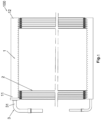
Fig. 1 is a schematic main view of a heat exchanger according to an embodiment of the present invention. -
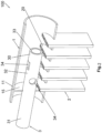
Fig. 2 is a partially cut-open schematic perspective view of a heat exchanger according to an embodiment of the present invention. -
Fig. 3 is a partially cut-open schematic perspective view of a heat exchanger according to another embodiment of the present invention. -
Fig. 4 is a partially cut-open schematic perspective view of a heat exchanger according to another embodiment of the present invention. -
Fig. 5 is a partially cut-open schematic perspective view of a heat exchanger according to another embodiment of the present invention. - The present invention is explained further below in conjunction with the accompanying drawings and specific implementations.
- Referring to
Figs 1 - 5 , aheat exchanger 100 according to embodiments of the present invention comprises: a header 1, the header 1 comprising afirst end 11 and asecond end 12 which are opposite each other, and further comprising an inner cavity; a plurality ofheat exchange tubes 2 arranged in the axial direction of the header 1, withends 20 of the plurality ofheat exchange tubes 2 being connected to the header 1; and aconnecting tube 3, the connectingtube 3 comprising a connectingpart 31 and asupply part 32 which is connected to the connectingpart 31 and also connected to thefirst end 11 of the header 1, thesupply part 32 being configured such that a flow direction of a heat exchange medium supplied to a predetermined number ofheat exchange tubes 2 through the inner cavity of the header 1 is not parallel to the axis of the header 1, the predetermined number ofheat exchange tubes 2 being a predetermined number ofheat exchange tubes 2 counted from thefirst end 11 of the header 1. For example, thesupply part 32 is configured such that the flow direction of the heat exchange medium supplied to the predetermined number ofheat exchange tubes 2 forms an angle greater than 30 degrees relative to the axis of the header 1. In the embodiments shown inFigs. 1-5 , the predetermined number ofheat exchange tubes 2 is a predetermined number ofheat exchange tubes 2 counted from the left end of the header 1. Theheat exchanger 100 may further comprise fins arranged alternately with theheat exchange tubes 2. The predetermined number is less than or equal to 10, or thesupply part 32 comprises a tube segment in the header 1, the tube segment having a length in the axial direction of the header 1, and the number ofheat exchange tubes 2 within the range of this length being less than or equal to 10. In addition, the predetermined number may be selected according to particular circumstances, for example, may be 3, 4, 5, 6, 7, 8 or more. - In some embodiments of the present invention, the ratio of the length, in the axial direction of the header 1, of a part of the connecting
tube 3 that is inserted in the inner cavity of the header 1 to the length of the inner cavity of the header 1 in the axial direction of the header 1 is less than 1/5. In the embodiments shown in the figures, there is no partition plate in the header 1; therefore, the length of the inner cavity of the header 1 in the axial direction of the header 1 is the length of the header 1 between two end caps, i.e. the length of the entire inner cavity. If a partition plate is provided in the header 1, the length of the inner cavity of the header 1 in the axial direction of the header 1 is the length between anend cap 15 at the first end and the partition plate (if one partition plate is provided), or is the length between theend cap 15 at the first end and the partition plate closest to theend cap 15 at the first end (if a plurality of partition plates are provided). - In some embodiments of the present invention, if the
heat exchanger 100 is acting as a condenser, the connectingtube 3 is an inlet tube of the heat exchanger, for inputting the heat exchange medium to the heat exchanger. - Referring to
Figs. 1 and5 , in some embodiments of the present invention, at least a portion of thesupply part 32 is inserted in thefirst end 11 of the header 1; and anend face 33 of anend 30 of thesupply part 32 that is remote from the connectingpart 31 is located at one side of a firstheat exchange tube 2 in the predetermined number ofheat exchange tubes 2, said side being remote from thesecond end 12 of the header 1, in the axial direction of the header 1, or is located at one side of the firstheat exchange tube 2 in the predetermined number ofheat exchange tubes 2, said side facing thefirst end 11 of the header 1, in the axial direction of the header 1. For example, the header 1 also has anend cap 15 disposed at thefirst end 11 of the header 1, and thesupply part 32 of theconnecting tube 3 is connected to theend cap 15 or inserted in the header 1 through an opening in theend cap 15. For example, thesupply part 32 is inserted in thefirst end 11 of the header 1 through the opening in theend cap 15 of the header 1. The firstheat exchange tube 2 is the leftmostheat exchange tube 2 in the figures. - Referring to
Figs. 2 - 5 , in some embodiments of the present invention, thesupply part 32 is inserted in thefirst end 11 of the header 1; and theend face 33 of theend 30 of thesupply part 32 that is remote from the connectingpart 31 is located between the firstheat exchange tube 2 in the predetermined number ofheat exchange tubes 2 and a finalheat exchange tube 2 in the predetermined number ofheat exchange tubes 2, in the axial direction of the header 1. For example, thesupply part 32 of the connectingtube 3 comprises an opening 34 penetrating a tube wall, and/or an opening at the end of thesupply part 32 that is remote from the connecting part. A cross section of the opening is parallel or inclined relative to the axis of the header 1. The opening 34 may face in any radial direction of the connectingtube 3, and theopening 34 may have any suitable shape. According to some examples of the present invention, theend 30 of thesupply part 32 of the connectingtube 3 that is remote from the connectingpart 31 is closed, or the cross-sectional area of theend 30 of thesupply part 32 of the connectingtube 3 that is remote from the connectingpart 31 is smaller than the cross-sectional area of another portion of thesupply part 32 of the connectingtube 3. In this way, the amount of heat exchange medium distributed to the predetermined number ofheat exchange tubes 2 can be increased. The finalheat exchange tube 2 is the rightmostheat exchange tube 2 shown in the figure in the predetermined number ofheat exchange tubes 2. - Referring to
Fig. 2 , in some embodiments of the present invention, the axis of thesupply part 32 of the connectingtube 3 is parallel to the axis of the header 1. - Referring to
Figs. 3 and4 , in some embodiments of the present invention, theend face 33 of theend 30 of thesupply part 32 that is remote from the connectingpart 31 faces toward theends 20 of the predetermined number ofheat exchange tubes 2 inserted in the header 1, and theend face 33 of theend 20 of thesupply part 32 is inclined relative to the axis of the header 1. Optionally, theend face 33 of theend 30 of thesupply part 32 that is remote from the connectingpart 31 may also not face toward theends 20 of the predetermined number ofheat exchange tubes 2 inserted in the header 1. For example, theend face 33 of theend 30 of thesupply part 32 that is remote from the connectingpart 31 is inclined relative to the axis of thesupply part 32. - Referring to
Figs. 1 ,3 and5 , in some embodiments of the present invention, the axis of thesupply part 32 of the connectingtube 3 is inclined relative to the axis of the header 1. For example, in the direction from thefirst end 11 to thesecond end 12 of the header 1, the axis of thesupply part 32 of the connectingtube 3 is inclined toward theends 20 of the predetermined number ofheat exchange tubes 2 inserted in the header 1, relative to the axis of the header 1. - Referring to
Fig. 4 , in some embodiments of the present invention, theend 30 of thesupply part 32 of the connectingtube 3 that is remote from the connectingpart 31 is bent relative to another portion of thesupply part 32. For example, theend 30 of thesupply part 32 of the connectingtube 3 that is remote from the connectingpart 31 is bent, relative to another portion of thesupply part 32, toward theends 20 of the predetermined number ofheat exchange tubes 2 inserted in the header 1. - Referring to
Fig. 4 , in some embodiments of the present invention, theheat exchanger 100 further comprises abaffle 4 disposed in the header 1. Thebaffle 4 is disposed at one side of theend 30 of thesupply part 32, said side being remote from the connectingpart 31, and thebaffle 4 may be spaced apart from theend 30 of thesupply part 32. Thebaffle 4 allows some of the heat exchange medium supplied by the connectingtube 3 to flow along the header 1 to the side of thebaffle 4 that is remote from thesupply part 32. In this way, the amount of heat exchange medium distributed to the predetermined number ofheat exchange tubes 2 can be increased. - Referring to
Fig. 5 , in some embodiments of the present invention, the cross-sectional area of thesupply part 32 of the connectingtube 3 gradually increases in the direction from thefirst end 11 to thesecond end 12 of the header 1. For example, in the direction from thefirst end 11 to thesecond end 12 of the header 1, the axis of thesupply part 32 of the connectingtube 3 is inclined toward theends 20 of the predetermined number ofheat exchange tubes 2 inserted in the header 1, relative to the axis of the header 1. - By using the heat exchanger according to the embodiments of the present invention, heat exchanger performance can be improved.
- For example, when a heat exchanger such as a micro-channel heat exchanger is used in an external machine of a heat pump unit, frost will form on the surface in winter (at this time the heat exchanger is an evaporator); once a certain amount of frost has formed, the unit will operate in reverse to perform defrosting, and the heat exchanger will become a condenser. When defrosting is being performed, high-temperature refrigerant enters the upper header 1 from the connecting
tube 3, then flows along theheat exchange tubes 2 such as flat tubes to the lower header, while removing the frost on theheat exchange tubes 2. - When the refrigerant enters the
upper header 2 from the connectingtube 3, a vortex low-pressure zone will form at the inlet of theheader 2, and this might result in a low flow rate of refrigerant in theheat exchange tubes 2 at corresponding positions (the heat exchange tubes that are closest to the edge of the heat exchanger), in turn resulting in incomplete removal of the frost on these heat exchange tubes. - According to an embodiment of the present invention, when the heat exchanger is in a defrosting state (at which time it is a condenser), the flow direction of outlet fluid at the end of the connecting tube is changed, eliminating the vortex low-pressure zone in the fluid at the inlet of the header, increasing the amount of high-temperature gaseous refrigerant in the heat exchange tubes in the inlet region, and speeding up defrosting.
- Although the above embodiments have been described, certain features in the above embodiments can be combined to form new embodiments.
Claims (21)
- A heat exchanger, comprising:a header, comprising a first end and a second end which are opposite each other, and further comprising an inner cavity;a plurality of heat exchange tubes arranged in an axial direction of the header, with ends of the plurality of heat exchange tubes being connected to the header; anda connecting tube, the connecting tube comprising a connecting part and a supply part which is connected to the connecting part and also connected to the first end of the header, the supply part being configured such that a flow direction of a heat exchange medium supplied to a predetermined number of heat exchange tubes through the inner cavity of the header is not parallel to an axis of the header, the predetermined number of heat exchange tubes being a predetermined number of heat exchange tubes counted from the first end of the header.
- The heat exchanger as claimed in claim 1, wherein:
at least a portion of the supply part is inserted in the first end of the header; and an end face of an end of the supply part that is remote from the connecting part is located at one side of a first heat exchange tube in the predetermined number of heat exchange tubes, said side being remote from the second end of the header, in the axial direction of the header. - The heat exchanger as claimed in claim 1, wherein:
the supply part is inserted in the first end of the header; and an end face of an end of the supply part that is remote from the connecting part is located between a first heat exchange tube in the predetermined number of heat exchange tubes and a final heat exchange tube in the predetermined number of heat exchange tubes, in the axial direction of the header. - The heat exchanger as claimed in claim 3, wherein:
the supply part of the connecting tube comprises an opening penetrating a tube wall, and/or an opening at the end of the supply part that is remote from the connecting part. - The heat exchanger as claimed in claim 4, wherein:
a cross section of the opening is parallel or inclined relative to the axis of the header. - The heat exchanger as claimed in any one of claims 1-3, wherein:
an axis of the supply part of the connecting tube is parallel to the axis of the header, or an axis of the supply part of the connecting tube is inclined relative to the axis of the header. - The heat exchanger as claimed in claim 4, wherein:
the end of the supply part of the connecting tube that is remote from the connecting part is closed, or a cross-sectional area of the end of the supply part of the connecting tube that is remote from the connecting part is smaller than a cross-sectional area of another portion of the supply part of the connecting tube. - The heat exchanger as claimed in any one of claims 1-3, wherein:
the end face of the end of the supply part is inclined relative to the axis of the header. - The heat exchanger as claimed in claim 8, wherein:
the end face of the end of the supply part that is remote from the connecting part faces toward the ends of the predetermined number of heat exchange tubes inserted in the header. - The heat exchanger as claimed in any one of claims 1-3, wherein:
in a direction from the first end to the second end of the header, an axis of the supply part of the connecting tube is inclined toward the ends of the predetermined number of heat exchange tubes inserted in the header, relative to the axis of the header. - The heat exchanger as claimed in any one of claims 1-3, wherein:
an end face of an end of the supply part that is remote from the connecting part is inclined relative to an axis of the supply part. - The heat exchanger as claimed in any one of claims 1-3, wherein:
an end of the supply part of the connecting tube that is remote from the connecting part is bent relative to another portion of the supply part. - The heat exchanger as claimed in any one of claims 1-3, wherein:
an end of the supply part of the connecting tube that is remote from the connecting part is bent toward the ends of the predetermined number of heat exchange tubes inserted in the header, relative to another portion of the supply part. - The heat exchanger as claimed in any one of claims 1-3, further comprising:
a baffle disposed in the header, the baffle being disposed at one side of the end of the supply part, said side being remote from the connecting part, and the baffle allowing some of the heat exchange medium supplied by the connecting tube to flow along the header to the side of the baffle that is remote from the supply part. - The heat exchanger as claimed in any one of claims 1-3, wherein:
a cross-sectional area of the supply part of the connecting tube gradually increases in a direction from the first end to the second end of the header. - The heat exchanger as claimed in claim 15, wherein:
in the direction from the first end to the second end of the header, an axis of the supply part of the connecting tube is inclined toward the ends of the predetermined number of heat exchange tubes inserted in the header, relative to the axis of the header. - The heat exchanger as claimed in claim 1, wherein:
if the heat exchanger is acting as a condenser, the connecting tube is an inlet tube of the heat exchanger, for inputting the heat exchange medium to the heat exchanger. - The heat exchanger as claimed in claim 1, wherein:
the predetermined number is less than or equal to 10, or the supply part comprises a tube segment in the header, the tube segment having a length in the axial direction of the header, and the number of heat exchange tubes within the range of this length being less than or equal to 10. - The heat exchanger as claimed in claim 1, wherein:
the supply part is configured such that the flow direction of the heat exchange medium supplied to the predetermined number of heat exchange tubes forms an angle greater than 30 degrees relative to the axis of the header. - The heat exchanger as claimed in claim 1, wherein:
the header also has an end cap disposed at the first end of the header, and the supply part of the connecting tube is connected to the end cap or inserted in the header through an opening in the end cap. - The heat exchanger as claimed in claim 1, wherein:
a ratio of the length, in the axial direction of the header, of a part of the connecting tube that is inserted in the inner cavity of the header to the length of the inner cavity of the header in the axial direction of the header is less than 1/5.
Applications Claiming Priority (3)
| Application Number | Priority Date | Filing Date | Title |
|---|---|---|---|
| CN202021462968.3U CN212566983U (en) | 2020-07-22 | 2020-07-22 | Heat exchanger |
| CN202010713874.7A CN113970258A (en) | 2020-07-22 | 2020-07-22 | Heat exchanger |
| PCT/CN2021/102076 WO2022017117A1 (en) | 2020-07-22 | 2021-06-24 | Heat exchanger |
Publications (1)
| Publication Number | Publication Date |
|---|---|
| EP4187190A1 true EP4187190A1 (en) | 2023-05-31 |
Family
ID=79729667
Family Applications (1)
| Application Number | Title | Priority Date | Filing Date |
|---|---|---|---|
| EP21845993.1A Withdrawn EP4187190A1 (en) | 2020-07-22 | 2021-06-24 | Heat exchanger |
Country Status (4)
| Country | Link |
|---|---|
| US (1) | US20230280113A1 (en) |
| EP (1) | EP4187190A1 (en) |
| MX (1) | MX2023000676A (en) |
| WO (1) | WO2022017117A1 (en) |
Families Citing this family (2)
| Publication number | Priority date | Publication date | Assignee | Title |
|---|---|---|---|---|
| WO2024042575A1 (en) * | 2022-08-22 | 2024-02-29 | 三菱電機株式会社 | Heat exchanger, and refrigeration cycle device |
| CN118420617A (en) * | 2023-01-31 | 2024-08-02 | 格格巫(珠海)生物科技有限公司 | Crystal form of a compound, preparation method and use thereof |
Family Cites Families (9)
| Publication number | Priority date | Publication date | Assignee | Title |
|---|---|---|---|---|
| JPH06159983A (en) * | 1992-11-20 | 1994-06-07 | Showa Alum Corp | Heat exchanger |
| US7806171B2 (en) * | 2004-11-12 | 2010-10-05 | Carrier Corporation | Parallel flow evaporator with spiral inlet manifold |
| KR20110035422A (en) * | 2009-09-30 | 2011-04-06 | 한라공조주식회사 | Condenser |
| JP2011185549A (en) * | 2010-03-09 | 2011-09-22 | Fuji Electric Co Ltd | Heat exchanger |
| US20120292004A1 (en) * | 2011-05-20 | 2012-11-22 | National Yunlin University Of Science And Technology | Heat exchanger |
| WO2013184522A1 (en) * | 2012-06-08 | 2013-12-12 | Modine Manufacturing Company | Heat exchanger, and method of distributing refrigerant therein |
| US9746255B2 (en) * | 2012-11-16 | 2017-08-29 | Mahle International Gmbh | Heat pump heat exchanger having a low pressure drop distribution tube |
| CN204165423U (en) * | 2014-08-12 | 2015-02-18 | 浙江盾安人工环境股份有限公司 | Micro-channel heat exchanger |
| CN212566983U (en) * | 2020-07-22 | 2021-02-19 | 丹佛斯有限公司 | Heat exchanger |
-
2021
- 2021-06-24 MX MX2023000676A patent/MX2023000676A/en unknown
- 2021-06-24 EP EP21845993.1A patent/EP4187190A1/en not_active Withdrawn
- 2021-06-24 WO PCT/CN2021/102076 patent/WO2022017117A1/en not_active Ceased
- 2021-06-24 US US18/005,690 patent/US20230280113A1/en not_active Abandoned
Also Published As
| Publication number | Publication date |
|---|---|
| MX2023000676A (en) | 2023-02-13 |
| US20230280113A1 (en) | 2023-09-07 |
| WO2022017117A1 (en) | 2022-01-27 |
Similar Documents
| Publication | Publication Date | Title |
|---|---|---|
| US20130306285A1 (en) | Heat exchanger and air conditioner | |
| EP2857788B1 (en) | Heat exchanger | |
| US10041710B2 (en) | Heat exchanger and air conditioner | |
| US20100115771A1 (en) | Heat exchanger, heat exchanger tubes and method | |
| US20080105420A1 (en) | Parallel Flow Heat Exchanger With Crimped Channel Entrance | |
| EP3619492B1 (en) | Heat exchanger for heat pump applications | |
| EP2097707B1 (en) | Heat exchanger design for improved performance and manufacturability | |
| WO2006055297A2 (en) | Parallel flow evaporator with variable channel insertion depth | |
| KR20170031556A (en) | Heat exchanger | |
| KR101837046B1 (en) | Heat exchanger | |
| US20230280113A1 (en) | Heat exchanger | |
| EP3832242B1 (en) | Condenser | |
| CN111059800B (en) | Microchannel condenser assembly, microchannel condenser and air conditioner | |
| EP3362759B1 (en) | Heat exchanger for residential hvac applications | |
| EP3789697B1 (en) | Heat exchanger and refrigeration cycle device | |
| EP3951301A1 (en) | Heat exchanger and refrigeration cycle device | |
| CN212566983U (en) | Heat exchanger | |
| KR20170029317A (en) | Heat exchanger | |
| CN116972454A (en) | a heat exchange system | |
| KR20000032399A (en) | Tube of heat exchanger | |
| EP3885690B1 (en) | Heat exchanger and refrigeration cycle device | |
| CN113970258A (en) | Heat exchanger | |
| JP7738754B2 (en) | Heat exchanger and refrigeration cycle device | |
| JP2020165578A (en) | Heat exchanger shunt | |
| KR200314025Y1 (en) | Fin tube type heat exchanger and airconditioner and refrigerator using the heat exchanger |
Legal Events
| Date | Code | Title | Description |
|---|---|---|---|
| STAA | Information on the status of an ep patent application or granted ep patent |
Free format text: STATUS: THE INTERNATIONAL PUBLICATION HAS BEEN MADE |
|
| PUAI | Public reference made under article 153(3) epc to a published international application that has entered the european phase |
Free format text: ORIGINAL CODE: 0009012 |
|
| STAA | Information on the status of an ep patent application or granted ep patent |
Free format text: STATUS: REQUEST FOR EXAMINATION WAS MADE |
|
| 17P | Request for examination filed |
Effective date: 20230110 |
|
| AK | Designated contracting states |
Kind code of ref document: A1 Designated state(s): AL AT BE BG CH CY CZ DE DK EE ES FI FR GB GR HR HU IE IS IT LI LT LU LV MC MK MT NL NO PL PT RO RS SE SI SK SM TR |
|
| DAV | Request for validation of the european patent (deleted) | ||
| DAX | Request for extension of the european patent (deleted) | ||
| STAA | Information on the status of an ep patent application or granted ep patent |
Free format text: STATUS: THE APPLICATION IS DEEMED TO BE WITHDRAWN |
|
| 18D | Application deemed to be withdrawn |
Effective date: 20240103 |