EP4187189A1 - Heat exchanger - Google Patents
Heat exchanger Download PDFInfo
- Publication number
- EP4187189A1 EP4187189A1 EP20946479.1A EP20946479A EP4187189A1 EP 4187189 A1 EP4187189 A1 EP 4187189A1 EP 20946479 A EP20946479 A EP 20946479A EP 4187189 A1 EP4187189 A1 EP 4187189A1
- Authority
- EP
- European Patent Office
- Prior art keywords
- heat transfer
- fins
- equal
- transfer tubes
- heat exchanger
- Prior art date
- Legal status (The legal status is an assumption and is not a legal conclusion. Google has not performed a legal analysis and makes no representation as to the accuracy of the status listed.)
- Withdrawn
Links
Images




Classifications
-
- F—MECHANICAL ENGINEERING; LIGHTING; HEATING; WEAPONS; BLASTING
- F28—HEAT EXCHANGE IN GENERAL
- F28F—DETAILS OF HEAT-EXCHANGE AND HEAT-TRANSFER APPARATUS, OF GENERAL APPLICATION
- F28F1/00—Tubular elements; Assemblies of tubular elements
- F28F1/10—Tubular elements and assemblies thereof with means for increasing heat-transfer area, e.g. with fins, with projections, with recesses
- F28F1/12—Tubular elements and assemblies thereof with means for increasing heat-transfer area, e.g. with fins, with projections, with recesses the means being only outside the tubular element
- F28F1/24—Tubular elements and assemblies thereof with means for increasing heat-transfer area, e.g. with fins, with projections, with recesses the means being only outside the tubular element and extending transversely
- F28F1/32—Tubular elements and assemblies thereof with means for increasing heat-transfer area, e.g. with fins, with projections, with recesses the means being only outside the tubular element and extending transversely the means having portions engaging further tubular elements
- F28F1/325—Fins with openings
-
- F—MECHANICAL ENGINEERING; LIGHTING; HEATING; WEAPONS; BLASTING
- F28—HEAT EXCHANGE IN GENERAL
- F28F—DETAILS OF HEAT-EXCHANGE AND HEAT-TRANSFER APPARATUS, OF GENERAL APPLICATION
- F28F1/00—Tubular elements; Assemblies of tubular elements
- F28F1/10—Tubular elements and assemblies thereof with means for increasing heat-transfer area, e.g. with fins, with projections, with recesses
- F28F1/12—Tubular elements and assemblies thereof with means for increasing heat-transfer area, e.g. with fins, with projections, with recesses the means being only outside the tubular element
- F28F1/24—Tubular elements and assemblies thereof with means for increasing heat-transfer area, e.g. with fins, with projections, with recesses the means being only outside the tubular element and extending transversely
- F28F1/32—Tubular elements and assemblies thereof with means for increasing heat-transfer area, e.g. with fins, with projections, with recesses the means being only outside the tubular element and extending transversely the means having portions engaging further tubular elements
-
- F—MECHANICAL ENGINEERING; LIGHTING; HEATING; WEAPONS; BLASTING
- F28—HEAT EXCHANGE IN GENERAL
- F28F—DETAILS OF HEAT-EXCHANGE AND HEAT-TRANSFER APPARATUS, OF GENERAL APPLICATION
- F28F21/00—Constructions of heat-exchange apparatus characterised by the selection of particular materials
- F28F21/08—Constructions of heat-exchange apparatus characterised by the selection of particular materials of metal
- F28F21/081—Heat exchange elements made from metals or metal alloys
- F28F21/084—Heat exchange elements made from metals or metal alloys from aluminium or aluminium alloys
-
- F—MECHANICAL ENGINEERING; LIGHTING; HEATING; WEAPONS; BLASTING
- F28—HEAT EXCHANGE IN GENERAL
- F28F—DETAILS OF HEAT-EXCHANGE AND HEAT-TRANSFER APPARATUS, OF GENERAL APPLICATION
- F28F21/00—Constructions of heat-exchange apparatus characterised by the selection of particular materials
- F28F21/08—Constructions of heat-exchange apparatus characterised by the selection of particular materials of metal
- F28F21/081—Heat exchange elements made from metals or metal alloys
- F28F21/085—Heat exchange elements made from metals or metal alloys from copper or copper alloys
Definitions
- the present disclosure relates to a heat exchanger.
- a mechanical tube expansion system which uses a pipe expander rod to expand the heat transfer tube (e.g., see Japanese Patent Laying-Open No. 2016-20757 ).
- a heat exchanger capable of handling a reduced refrigerant of recent years increasingly includes a heat transfer tube that has a reduced diameter.
- the ratio of the contact thermal resistance to the entire thermal resistance of the heat exchanger is confirmed to increase with a reduction of the outer diameter of the heat transfer tube. Therefore, deterioration of the heat exchange performance associated with an increase of such a ratio is a concern with the heat exchanger capable of handling a reduced refrigerant.
- a primary object of the present disclosure is to provide a heat exchanger capable of inhibiting the deterioration of heat exchanger performance associated with a contact thermal resistance.
- a heat exchanger includes: a plurality of fins disposed, spaced apart from each other; and a plurality of heat transfer tubes inserted in the plurality of fins.
- the plurality of heat transfer tubes have round profiles.
- the plurality of heat transfer tubes have outer circumferential surfaces in contact with the plurality of fins.
- the plurality of heat transfer tubes have outer diameters D 0 of 5.4 mm or less.
- the plurality of fins and the heat transfer tubes are disposed so that ratios tf/D 0 of thicknesses tf of the plurality of fins to the outer diameters D 0 are 0.03 or greater.
- a heat exchanger can be provided which is capable of inhibiting deterioration of the heat exchanger performance associated with a contact thermal resistance.
- Figs. 1 and 2 introduce a first direction X, a second direction Y, and a third direction Z, which intersect with each other.
- a heat exchanger 10 is a plate-fin heat exchanger.
- the heat exchanger 10 includes multiple fins 20 and multiple heat transfer tubes 30.
- the fins 20 are plate fins.
- the fins 20 each extend along the first direction X and the third direction Z.
- the fins 20 are disposed, spaced apart from each other in the second direction Y.
- the number of fins 20 may be two or more, for example, three or more fins 20.
- Three or more fins 20 are equidistantly disposed in the second direction Y, for example.
- Multiple fin collars are formed on each fin 20. Each fin collar is disposed so as to have one heat transfer tube 30 inserted therethrough.
- the center-to-center distance between adjacent two fins 20 in the second direction Y will be referred to as a fin pitch Fp.
- each fin 20 has a first surface 20A facing the first surface 20A of an adjacent fin 20 in the second direction Y, and a second surface 20B extending in a direction interesting with the first surface 20A and in contact with an outer circumferential surface of the heat transfer tube 30.
- the second surface 20B is an inner circumferential surface of the fin collar of each fin 20.
- the length of the second surface 20B in the second direction Y is equal to a thickness tf of the fin 20, for example.
- the heat transfer tubes 30 are round tubes. Stated differently, each heat transfer tube 30 has a round profile.
- the heat transfer tube 30 is inserted into the fin 20.
- the outer circumferential surface of the heat transfer tube 30 is in contact with the fin 20.
- the heat transfer tubes 30 are expanded by a mechanical tube expansion system, for example.
- one or more grooves are formed in the inner circumferential surface of each heat transfer tube 30.
- the heat transfer tubes 30 are what is called grooved-heat transfer tubes.
- the heat transfer tube 30 is not brazed to the fin 20.
- heat transfer tube 30 is formed of a single material, for example. Stated differently, the heat transfer tube 30 is not formed of a clad material.
- the heat transfer tube 30 may be brazed to the fin 20.
- the heat transfer tube 30 is formed of a clad material.
- intratube inside the heat transfer tube 30
- extratube outside the heat transfer tube 30
- the heat transfer tubes 30 extend along the second direction Y.
- the number of heat transfer tubes 30 may be one or more, for example, four or more heat transfer tubes 30.
- the heat transfer tubes 30 are disposed spaced apart by a spacing Lp (see Fig. 2 ) from each other in the first direction X and spaced apart by a spacing D p (see Fig. 2 ) from each other in the third direction Z.
- a spacing Lp see Fig. 2
- D p see Fig. 2
- the number of columns of the heat transfer tubes 30 in the first direction X may be one or more, for example, three or more columns.
- the number of tiers of heat transfer tubes 30 in the third direction Z may be one or more, for example, three or more tiers.
- the distance between the central axes of adjacent two heat transfer tubes 30 in the first direction X will be referred to as a column pitch L P .
- the distance between the central axes of adjacent two heat transfer tubes 30 in the third direction Z will be referred to as a tier pitch D P .
- Examples of the materials comprising the fins 20 include, but are not particularly limited to, copper (Cu) or aluminum (Al).
- the material comprising each fin 20 includes Al
- the material comprising each heat transfer tube 30 includes Cu.
- a flow passage R1 is formed between adjacent two fins 20 in the second direction Y.
- a first heat-transfer medium such as an air flows through the flow passage R1 in the first direction X.
- a flow passage R2 is formed inside each heat transfer tube 30.
- a second heat-transfer medium such as a refrigerant flows through the flow passage R2 in the second direction Y. The first heat-transfer medium exchanges heat with the second heat-transfer medium via the fin 20 and the heat transfer tube 30.
- the fins 20 and the heat transfer tubes 30 are disposed so that a ratio tf/D 0 of the thickness tf (unit: mm) of each fin 20 to the outer diameter D 0 (unit: mm) of each heat transfer tube 30 is greater than or equal to 0.03.
- the outer diameters D 0 of the heat transfer tubes 30 are for example, less than or equal to 5.4 mm.
- the fins 20 and the heat transfer tubes 30 are disposed so that a ratio AoK/ ⁇ P of a heat exchanger performance AoK to an extratube pressure loss ⁇ P (unit: Pa) is not less than 100% when the outer diameters D 0 of the fins 20 and the heat transfer tubes 30 are at least less than or equal to 5.4 mm.
- the outer diameters D 0 of the heat transfer tubes 30 are, for example, greater than or equal to 5.2 mm and less than or equal to 5.4 mm.
- the fins 20 and the heat transfer tubes 30 are disposed so that the ratio tf/D 0 is greater than or equal to 0.03 and less than or equal to 0.034.
- the fins 20 and the heat transfer tubes 30 are disposed so that the ratio AoK/ ⁇ P of the heat exchanger performance AoK to the extratube pressure loss ⁇ P is 102% or greater when the outer diameters D 0 of the fins 20 and the heat transfer tubes 30 are greater than or equal to 5.2 mm and less than or equal to 5.4 mm.
- the outer diameters D 0 of the heat transfer tubes 30 are, for example, greater than or equal to 3.6 mm and less than or equal to 3.8 mm.
- the fins 20 and the heat transfer tubes 30 are disposed so that the ratio tf/D 0 is greater than or equal to 0.034 and less than or equal to 0.058.
- the fins 20 and the heat transfer tubes 30 are disposed so that the ratio AoK/ ⁇ P of the heat exchanger performance AoK to the extratube pressure loss ⁇ P is 102% or greater when the outer diameters D 0 of the fins 20 and the heat transfer tubes 30 are greater than or equal to 3.6 mm and less than or equal to 3.8 mm.
- the outer diameter D 0 is the outer diameter of the expanded heat transfer tube 30.
- the tube expansion rate is, but not particularly limited to, greater than or equal to 5% and less than or equal to 8%, for example.
- the thickness tf and the outer diameter D 0 are, while they can be measured by any method, measured by a vernier caliper, for example.
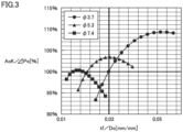
- Fig. 3 is a graph showing the ratio tf/D 0 versus the ratio AoK/ ⁇ P, more specifically, a graph showing changes in ratio AoK/ ⁇ P with varying fin thickness tf relative to the outer diameter D 0 of the heat transfer tube.
- the ratio tf/D 0 is indicated on the horizontal axis and the ratio AoK/ ⁇ P is indicated on the vertical axis.
- Fig. 3 shows changes in ratio AoK/ ⁇ P with varying thickness tf of the fin in contact with the heat transfer tube that has the outer diameter D 0 of 3.7 mm, 5.3 mm, and 7.4 mm.
- Fig. 4 is a graph showing changes in ratio AoK/ ⁇ P with varying thickness tf of the fin in contact with the heat transfer tube that has the outer diameter D 0 of 5.3 mm.
- Fig. 5 is a graph showing changes in ratio AoK/ ⁇ P with varying thickness tf of the fin in contact with the heat transfer tube that has the outer diameter D 0 of 3.7 mm.
- the thickness tf is indicated on the horizontal axis
- the ratio AoK/ ⁇ P is indicated on the vertical axis.
- the ratio AoK/ ⁇ P is confirmed as being at its peak when the thickness tf is varied relative to a given outer diameter D 0 .
- the ratio AoK/ ⁇ P is 100% or greater if the ratio tf/D 0 is greater than or equal to 0.021 and less than or equal to 0.04.
- the ratio AoK/ ⁇ P is 102% or greater if the ratio tf/D 0 is greater than or equal to 0.026 and less than or equal to 0.034.
- the ratio AoK/ ⁇ P is 103% or greater if the ratio tf/D 0 is 0.03.
- the ratio AoK/ ⁇ P is 100% or greater if the thickness tf of the fin 20 is greater than or equal to 0.11 mm and less than or equal to 0.21 mm.
- the ratio AoK/ ⁇ P is 102% or greater if the thickness tf is thicker than 0.12 mm and thinner than 0.20 mm.
- the ratio AoK/ ⁇ P is 103% or greater if the thickness tf is greater than or equal to 0.15 mm and less than or equal to 0.17 mm.
- the ratio AoK/ ⁇ P is at the maximum if the thickness tf is greater than or equal to 0.15 mm and less than or equal to 0.16 mm.
- the ratio AoK/ ⁇ P is 100% or greater if the ratio tf/D 0 is greater than or equal to 0.03.
- the ratio AoK/ ⁇ P is 103% or greater if the ratio tf/D 0 is greater than or equal to 0.034.
- the ratio AoK/ ⁇ P is 108% or greater if the ratio tf/D 0 is greater than or equal to 0.046 and less than or equal to 0.058.
- the ratio AoK/ ⁇ P is 100% or greater if the thickness tf of the fin 20 is greater than or equal to 0.11 mm and less than or equal to 0.21 mm.
- the ratio AoK/ ⁇ P is 103% or greater if the thickness tf is greater than or equal to 0.12 mm.
- the ratio AoK/ ⁇ P is 107% or greater if the thickness tf is greater than or equal to 0.15 mm.
- the ratio AoK/ ⁇ P is 108% or greater if the thickness tf is greater than or equal to 0.17 mm and less than or equal to 0.21 mm.
- the ratio AoK/ ⁇ P is at the maximum if the thickness tf is greater than or equal to 0.18 mm and less than or equal to 0.20 mm.
- Equation (1) A method of calculation of the heat exchanger performance AoK and the pressure loss ⁇ P is as follows:
- the heat exchanger performance AoK is defined by the following Equation (1), using an intratube heat transfer coefficient ⁇ i , a contact heat transfer coefficient ⁇ c , and an extratube heat transfer coefficient ⁇ a . Note that Equation (1) disregards the thermal resistance of the heat transfer tube in the direction of thickness thereof and the thermal resistance due to fouling in the tube because they are very small, as compared to the contact thermal resistance between the heat transfer tube and the refrigerant flowing therethrough, and the contact thermal resistance between the heat transfer tube and an air flowing outside the heat transfer tube.
- An intratube heat transfer area A pi , a contact area A c o of the fin and the heat transfer tube, a surface area A P of the outer circumferential surface of the heat transfer tube, and a surface area A F of the fin in Equation (1) are set as specifications of the heat exchanger 10. These areas are in unit of m 2 .
- a Prandtl number P rl of the refrigerant and a thermal conductivity k l (unit: W/m ⁇ K) of the refrigerant in Equation (2), and a density ⁇ 1 (unit: g/m 3 ) of a saturated liquid, a viscous modulus ⁇ l of the saturated liquid, a density ⁇ v (unit: g/m 3 ) of a saturated vapor, and a viscous modulus ⁇ v of the saturated vapor in Equation (3) are physical property values of the refrigerant.
- An inner diameter d i (unit: m) of the heat transfer tube in Equation (3) is set as a specification of the heat exchanger 10.
- a vapor quality x in Equation (3) is a representative vapor quality, specifically, 0.5.
- the intratube heat transfer coefficient ⁇ i calculated using Equations (2) and (3) is an average heat transfer coefficient.
- ⁇ d (unit: m) is an amount of expansion of tube, that is, a difference between the outer diameter D 0 of the expanded heat transfer tube 30, and the diameter of the fin collar before the heat transfer tube 30 is expanded.
- An air Nusselt number Nu in Equation (5) is calculated using Equation (7), if a calculated value of an air Reynolds number Re defined by Equation (6) is less than a threshold (e.g., 400).
- An air Reynolds number Re a_lRe in Equation (7) is calculated by assigning an average velocity of fluid Ve ac at a free through-flow cross-sectional area A c calculated using Equation (8) to an average velocity of fluid Ve of Equation (6), and assigning a representative inter-fin length De c relative to a free-flow volume Vo to a representative inter-fin length De of Equation (6).
- the air Nusselt number Nu of Equation (5) is calculated using Equation (9), if the calculated value of the air Reynolds number Re defined by Equation (6) is equal to or greater than or equal to the threshold (e.g., 400).
- the air Reynolds number Re a_hRe of Equation (9) is calculated by assigning an average velocity of fluid Ve max at a minimum flow passage cross-sectional area A min calculated using Equation (10) to the average velocity of fluid Ve of Equation (6), and assigning a representative inter-fin length D min relative to a minimum free through-flow volume V min to the representative inter-fin length De of Equation (6).
- the thermal conductivity k a (unit: W/(m ⁇ k)) of air of Equation (5), the dynamic viscous modulus v a of air of Equation (6), and the Prandtl number Pra of air are physical property values of air that are determined depending on the temperature, pressure, etc.
- ⁇ a and ⁇ ai are a density of air.
- a number of columns N L of the heat transfer tube and the column pitch L P (unit: m) of the heat transfer tubes of Equations (7) and (9), and the fin pitch F p (unit: m) and the tier pitch D P (unit: m) of the heat transfer tubes of Equations (8) and (10) are set as specifications of the heat exchanger.
- a constant C 0 is 2.1
- a constant C 1 is 0.38
- C 0 is 0.12
- C 1 is 0.64.
- a fin efficiency ⁇ of Equation (1) is calculated using Equations (11) and (12) below.
- a thermal conductivity k f (unit: W / (m ⁇ k)) of the fin, an equivalent diameter (unit: m) of the fin, and a diameter Dc (unit: m) of the fin collar before the heat transfer tube 30 is expanded in Equation (11) below are set as specifications of the heat exchanger.
- the extratube pressure loss ⁇ P is calculated using Equation (13) below, if the calculated value of the air Reynolds number Re defined by Equation (6) is less than the threshold (e.g., 400).
- the representative inter-fin length De c of Equation (13) is calculated relative to a free-flow volume V c .
- a flow-loss factor flRe of Equation (13) is calculated using Equation (14).
- the extratube pressure loss ⁇ P is calculated using Equation (15) below, if a calculated value of the air Reynolds number Re defined by Equation (6) is greater than or equal to the threshold (e.g., 400).
- a representative inter-fin length De min of Equation (15) is calculated relative to a minimum flow passage cross-sectional area V min .
- the flow-loss factor flRe of Equation (15) is calculated using Equation (16).
- the ratio of the contact thermal resistance to the entire thermal resistance of the heat exchanger is confirmed to increase with a reduction of the outer diameter of the heat transfer tube to less than 7 mm, as shown in Fig. 8 . Therefore, deterioration of the heat exchange performance associated with an increase of the ratio above is a concern with a heat exchanger.
- it is contemplated to increase the contact heat transfer coefficient ⁇ c calculated from Equation (4).
- at least one of an amount of tube expansion ⁇ d and the fin thickness tf needs to be increased in order to increase the contact heat transfer coefficient ⁇ c .
- Fig. 6 is a graph showing the amount of tube expansion ⁇ d versus the contact heat transfer coefficient ⁇ c calculated from Equation (4), where the fin thickness tf is constant and the amount of tube expansion ⁇ d is varied.
- the contact heat transfer coefficient ⁇ c is independent of the outer diameter D 0 of the heat transfer tube, and increases with an increase of the amount of tube expansion ⁇ d.
- an increase of the amount of tube expansion increases the likelihood of causing failures in manufacturing such as breakage of fin collars.
- the contact heat transfer coefficient ⁇ c increases with an increase of the fin thickness tf.
- An increase of the wind speed of the air flowing between the fans that is, increases of the average velocity of fluid Ve ac of Equation (8) and the average velocity of fluid Ve max of Equation (10) increase an extratube transfer coefficient ⁇ a , where the fin pitch F p is constant and the fin thickness tf is increased.
- an increase of the wind speed of the air flowing between the fins increases the average velocity of fluid Ve ac of Equation (13) and the average velocity of fluid Ve max of Equation (15), thereby increasing the extratube pressure loss ⁇ P 0 .
- the flow rate of the air flowing between the fans may be less than a sufficient rate expected, and the heat exchanger performance may therefore not be exercised as expected.
- the outer diameters D 0 of the heat transfer tubes 30 are less than or equal to 5.4 mm, and the fins 20 and the heat transfer tubes 30 are disposed so that the ratio tf/D 0 of the thickness tf of each fin 20 to the outer diameter D 0 of each heat transfer tube 30 is greater than or equal to 0.03. Therefore, the ratio AoK/ ⁇ P of the heat exchanger 10 is 100% or greater, as shown in Figs. 3 through 5 .
- the fins 20 and the heat transfer tubes 30 are disposed so that an increase of the extratube pressure loss ⁇ P 0 can be inhibited, while increasing the heat exchanger performance AoK by increasing the contact heat transfer coefficient ⁇ c .
- the heat exchanger performance of the heat exchanger 10 is higher than the heat exchanger performance of the heat exchanger in which the fin thickness tf is simply increased in order to inhibit an increase of the contact thermal resistance.
- Figs. 3 and 4 show only results of calculation when the outer diameter D 0 is 5.3 mm, it should be noted that the inventors confirmed that the ratio AoK/ ⁇ P is 100% or greater even when the outer diameter D 0 is 5.4 mm, if the ratio tf/D 0 is 0.03 or greater.
- multiple fins 20 and multiple heat transfer tubes 30 are disposed so that the outer diameter D 0 is greater than or equal to 5.2 mm and less than or equal to 5.4 mm and the ratio tf/D 0 is 0.034 or less.
- multiple fins 20 and multiple heat transfer tubes 30 are disposed so that the outer diameter D 0 is greater than or equal to 3.6 mm and less than or equal to 3.8 mm and the ratio tf/D 0 is greater than or equal to 0.034 and less than or equal to 0.058.
- each heat transfer tube 30 may not be formed of a clad material. In other words, the heat transfer tube 30 may be formed of a single material.
- the material cost of the heat transfer tubes 30 and the manufacturing cost associated with brazing can be reduced.
- Fig. 7 is a cross-sectional view of a variation of the heat exchanger 10 of Fig. 1 .
- each fin 20 has the first surface 20A facing the first surface 20A of an adjacent fin 20 in the second direction Y, and the second surface 20B extending in a direction intersecting with the first surface 20A.
- a portion of the first surface 20A is an inner circumferential surface of the fin collar of each fin 20 and in contact with the outer circumferential surface of the heat transfer tube 30.
- the ratio AoK/ ⁇ P in the heat exchanger 10 of Fig. 7 is 100% or greater if the ratio tf/D 0 is greater than or equal to 0.03, as with the heat exchanger 10 of Fig. 1 .
Landscapes
- Engineering & Computer Science (AREA)
- Physics & Mathematics (AREA)
- Thermal Sciences (AREA)
- Mechanical Engineering (AREA)
- General Engineering & Computer Science (AREA)
- Geometry (AREA)
- Heat-Exchange Devices With Radiators And Conduit Assemblies (AREA)
Abstract
Description
- The present disclosure relates to a heat exchanger.
- As a method for enhancing the adhesion in a heat exchanger between a fin and a heat transfer tube that has a round profile, a mechanical tube expansion system is known which uses a pipe expander rod to expand the heat transfer tube (e.g., see
Japanese Patent Laying-Open No. 2016-20757 - PTL 1:
Japanese Patent Laying-Open No. 2016-20757 - Even with the mechanical tube expansion system, the heat exchange performance deteriorates if the contact thermal resistance between the fin and the heat transfer tube is high.
- In particular, a heat exchanger capable of handling a reduced refrigerant of recent years, increasingly includes a heat transfer tube that has a reduced diameter. As shown in
Fig. 8 , the ratio of the contact thermal resistance to the entire thermal resistance of the heat exchanger is confirmed to increase with a reduction of the outer diameter of the heat transfer tube. Therefore, deterioration of the heat exchange performance associated with an increase of such a ratio is a concern with the heat exchanger capable of handling a reduced refrigerant. - A primary object of the present disclosure is to provide a heat exchanger capable of inhibiting the deterioration of heat exchanger performance associated with a contact thermal resistance.
- A heat exchanger according to the present disclosure includes: a plurality of fins disposed, spaced apart from each other; and a plurality of heat transfer tubes inserted in the plurality of fins. The plurality of heat transfer tubes have round profiles. The plurality of heat transfer tubes have outer circumferential surfaces in contact with the plurality of fins. The plurality of heat transfer tubes have outer diameters D0 of 5.4 mm or less. The plurality of fins and the heat transfer tubes are disposed so that ratios tf/D0 of thicknesses tf of the plurality of fins to the outer diameters D0 are 0.03 or greater.
- According to the present disclosure, a heat exchanger can be provided which is capable of inhibiting deterioration of the heat exchanger performance associated with a contact thermal resistance.
-
-
Fig. 1 is a partial sectional view of a heat exchanger according to the present embodiment. -
Fig. 2 is a partial sectional view for illustrating arrangement of multiple heat transfer tubes in the heat exchanger ofFig. 1 . -
Fig. 3 is a graph showing a ratio tf/D0 of a thickness tf of a fin to an outer diameter D0 of the heat transfer tube versus a ratio AoK/ΔP of heat exchange performance A0K to an extratube pressure loss ΔP0. -
Fig. 4 is a graph showing the thickness tf of the fin where the heat transfer tube has the outer diameter D0 of 5.3 mm versus the ratio of the heat exchange performance A0K to the extratube pressure loss ΔP0. -
Fig. 5 is a graph showing the thickness tf of the fin where the heat transfer tube has the outer diameter D0 of 5.3 mm versus the ratio of the heat exchange performance A0K to the extratube pressure loss ΔP0. -
Fig. 6 is a graph showing an amount by which the heat transfer tube is expanded versus a contact heat transfer coefficient between the fin and the heat transfer tube. -
Fig. 7 is a partial sectional view of a variation of the heat exchanger ofFig. 1 . -
Fig. 8 is a graph showing the outer diameter D0 of the heat transfer tube versus a ratio of a contact thermal resistance between the fin and the heat transfer tube to an entire thermal resistance of the heat exchanger. - Hereinafter, the present embodiment will be described, with reference to the accompanying drawings. Note that, for purpose of explanation,
Figs. 1 and 2 introduce a first direction X, a second direction Y, and a third direction Z, which intersect with each other. - As shown in
Figs. 1 and 2 , aheat exchanger 10 according to the present embodiment is a plate-fin heat exchanger. Theheat exchanger 10 includesmultiple fins 20 and multipleheat transfer tubes 30. - The fins 20 are plate fins. The
fins 20 each extend along the first direction X and the third direction Z. Thefins 20 are disposed, spaced apart from each other in the second direction Y. The number offins 20 may be two or more, for example, three or more fins 20. Three ormore fins 20 are equidistantly disposed in the second direction Y, for example. Multiple fin collars are formed on eachfin 20. Each fin collar is disposed so as to have oneheat transfer tube 30 inserted therethrough. The center-to-center distance between adjacent twofins 20 in the second direction Y will be referred to as a fin pitch Fp. - As shown in
Fig. 1 , eachfin 20 has afirst surface 20A facing thefirst surface 20A of anadjacent fin 20 in the second direction Y, and asecond surface 20B extending in a direction interesting with thefirst surface 20A and in contact with an outer circumferential surface of theheat transfer tube 30. Thesecond surface 20B is an inner circumferential surface of the fin collar of eachfin 20. The length of thesecond surface 20B in the second direction Y is equal to a thickness tf of thefin 20, for example. - The
heat transfer tubes 30 are round tubes. Stated differently, eachheat transfer tube 30 has a round profile. Theheat transfer tube 30 is inserted into thefin 20. The outer circumferential surface of theheat transfer tube 30 is in contact with thefin 20. Theheat transfer tubes 30 are expanded by a mechanical tube expansion system, for example. For example, one or more grooves are formed in the inner circumferential surface of eachheat transfer tube 30. For example, theheat transfer tubes 30 are what is called grooved-heat transfer tubes. For example, theheat transfer tube 30 is not brazed to the fin 20. In this case,heat transfer tube 30 is formed of a single material, for example. Stated differently, theheat transfer tube 30 is not formed of a clad material. Note that theheat transfer tube 30 may be brazed to thefin 20. In this case, preferably, theheat transfer tube 30 is formed of a clad material. In the following, inside theheat transfer tube 30 will be referred to as intratube, and outside theheat transfer tube 30 will be referred to as extratube. - The
heat transfer tubes 30 extend along the second direction Y. The number ofheat transfer tubes 30 may be one or more, for example, four or moreheat transfer tubes 30. Theheat transfer tubes 30 are disposed spaced apart by a spacing Lp (seeFig. 2 ) from each other in the first direction X and spaced apart by a spacing Dp (seeFig. 2 ) from each other in the third direction Z. Note that the arrangement of theheat transfer tubes 30 along the first direction X in which an air flows will be referred to as a column, and the arrangement of theheat transfer tubes 30 along the third direction Z will be referred to as an array. The number of columns of theheat transfer tubes 30 in the first direction X may be one or more, for example, three or more columns. The number of tiers ofheat transfer tubes 30 in the third direction Z may be one or more, for example, three or more tiers. The distance between the central axes of adjacent twoheat transfer tubes 30 in the first direction X will be referred to as a column pitch LP. The distance between the central axes of adjacent twoheat transfer tubes 30 in the third direction Z will be referred to as a tier pitch DP. - Examples of the materials comprising the
fins 20 include, but are not particularly limited to, copper (Cu) or aluminum (Al). Examples of the materials comprising theheat transfer tube 30, but are not particularly limited to, Cu or Al. For example, the material comprising eachfin 20 includes Al, and the material comprising eachheat transfer tube 30 includes Cu. - A flow passage R1 is formed between adjacent two
fins 20 in the second direction Y. A first heat-transfer medium such as an air flows through the flow passage R1 in the first direction X. A flow passage R2 is formed inside eachheat transfer tube 30. A second heat-transfer medium such as a refrigerant flows through the flow passage R2 in the second direction Y. The first heat-transfer medium exchanges heat with the second heat-transfer medium via thefin 20 and theheat transfer tube 30. - The
fins 20 and theheat transfer tubes 30 are disposed so that a ratio tf/D0 of the thickness tf (unit: mm) of eachfin 20 to the outer diameter D0 (unit: mm) of eachheat transfer tube 30 is greater than or equal to 0.03. The outer diameters D0 of theheat transfer tubes 30 are for example, less than or equal to 5.4 mm. Stated from a different perspective, thefins 20 and theheat transfer tubes 30 are disposed so that a ratio AoK/ΔP of a heat exchanger performance AoK to an extratube pressure loss ΔP (unit: Pa) is not less than 100% when the outer diameters D0 of thefins 20 and theheat transfer tubes 30 are at least less than or equal to 5.4 mm. - The outer diameters D0 of the
heat transfer tubes 30 are, for example, greater than or equal to 5.2 mm and less than or equal to 5.4 mm. In this case, preferably, thefins 20 and theheat transfer tubes 30 are disposed so that the ratio tf/D0 is greater than or equal to 0.03 and less than or equal to 0.034. Stated from a different perspective, thefins 20 and theheat transfer tubes 30 are disposed so that the ratio AoK/ΔP of the heat exchanger performance AoK to the extratube pressure loss ΔP is 102% or greater when the outer diameters D0 of thefins 20 and theheat transfer tubes 30 are greater than or equal to 5.2 mm and less than or equal to 5.4 mm. - The outer diameters D0 of the
heat transfer tubes 30 are, for example, greater than or equal to 3.6 mm and less than or equal to 3.8 mm. In this case, preferably, thefins 20 and theheat transfer tubes 30 are disposed so that the ratio tf/D0 is greater than or equal to 0.034 and less than or equal to 0.058. Stated from a different perspective, thefins 20 and theheat transfer tubes 30 are disposed so that the ratio AoK/ΔP of the heat exchanger performance AoK to the extratube pressure loss ΔP is 102% or greater when the outer diameters D0 of thefins 20 and theheat transfer tubes 30 are greater than or equal to 3.6 mm and less than or equal to 3.8 mm. Methods of calculation of the heat exchanger performance AoK and the extratube pressure loss ΔP will be described below. - Note that, if the
heat transfer tube 30 is expanded by the mechanical tube expansion system, the outer diameter D0 is the outer diameter of the expandedheat transfer tube 30. The tube expansion rate is, but not particularly limited to, greater than or equal to 5% and less than or equal to 8%, for example. The thickness tf and the outer diameter D0 are, while they can be measured by any method, measured by a vernier caliper, for example. -
Fig. 3 is a graph showing the ratio tf/D0 versus the ratio AoK/ΔP, more specifically, a graph showing changes in ratio AoK/ΔP with varying fin thickness tf relative to the outer diameter D0 of the heat transfer tube. InFig. 3 , the ratio tf/D0 is indicated on the horizontal axis and the ratio AoK/ΔP is indicated on the vertical axis. As one example,Fig. 3 shows changes in ratio AoK/ΔP with varying thickness tf of the fin in contact with the heat transfer tube that has the outer diameter D0 of 3.7 mm, 5.3 mm, and 7.4 mm. -
Fig. 4 is a graph showing changes in ratio AoK/ΔP with varying thickness tf of the fin in contact with the heat transfer tube that has the outer diameter D0 of 5.3 mm.Fig. 5 is a graph showing changes in ratio AoK/ΔP with varying thickness tf of the fin in contact with the heat transfer tube that has the outer diameter D0 of 3.7 mm. InFigs. 4 and 5 , the thickness tf is indicated on the horizontal axis, and the ratio AoK/ΔP is indicated on the vertical axis. - As shown in
Figs. 3 ,4, and 5 , the ratio AoK/ΔP is confirmed as being at its peak when the thickness tf is varied relative to a given outer diameter D0. - As shown in
Fig. 3 , when the outer diameter D0 is 5.3 mm, the ratio AoK/ΔP is 100% or greater if the ratio tf/D0 is greater than or equal to 0.021 and less than or equal to 0.04. The ratio AoK/ΔP is 102% or greater if the ratio tf/D0 is greater than or equal to 0.026 and less than or equal to 0.034. The ratio AoK/ΔP is 103% or greater if the ratio tf/D0 is 0.03. - As shown in
Fig. 4 , when the outer diameter D0 is 5.3 mm, the ratio AoK/ΔP is 100% or greater if the thickness tf of thefin 20 is greater than or equal to 0.11 mm and less than or equal to 0.21 mm. The ratio AoK/ΔP is 102% or greater if the thickness tf is thicker than 0.12 mm and thinner than 0.20 mm. The ratio AoK/ΔP is 103% or greater if the thickness tf is greater than or equal to 0.15 mm and less than or equal to 0.17 mm. The ratio AoK/ΔP is at the maximum if the thickness tf is greater than or equal to 0.15 mm and less than or equal to 0.16 mm. - As shown in
Fig. 3 , when the outer diameter D0 is 3.7 mm, the ratio AoK/ΔP is 100% or greater if the ratio tf/D0 is greater than or equal to 0.03. The ratio AoK/ΔP is 103% or greater if the ratio tf/D0 is greater than or equal to 0.034. The ratio AoK/ΔP is 108% or greater if the ratio tf/D0 is greater than or equal to 0.046 and less than or equal to 0.058. - As shown in
Fig. 5 , when the outer diameter D0 is 3.7 mm, the ratio AoK/ΔP is 100% or greater if the thickness tf of thefin 20 is greater than or equal to 0.11 mm and less than or equal to 0.21 mm. The ratio AoK/ΔP is 103% or greater if the thickness tf is greater than or equal to 0.12 mm. The ratio AoK/ΔP is 107% or greater if the thickness tf is greater than or equal to 0.15 mm. The ratio AoK/ΔP is 108% or greater if the thickness tf is greater than or equal to 0.17 mm and less than or equal to 0.21 mm. The ratio AoK/ΔP is at the maximum if the thickness tf is greater than or equal to 0.18 mm and less than or equal to 0.20 mm. - A method of calculation of the heat exchanger performance AoK and the pressure loss ΔP is as follows:
The heat exchanger performance AoK is defined by the following Equation (1), using an intratube heat transfer coefficient αi, a contact heat transfer coefficient αc, and an extratube heat transfer coefficient αa. Note that Equation (1) disregards the thermal resistance of the heat transfer tube in the direction of thickness thereof and the thermal resistance due to fouling in the tube because they are very small, as compared to the contact thermal resistance between the heat transfer tube and the refrigerant flowing therethrough, and the contact thermal resistance between the heat transfer tube and an air flowing outside the heat transfer tube. The heat transfer coefficients αi, αc, and αa are in unit of W / (m2 · K).
[MATH 1]
- An intratube heat transfer area Api, a contact area Aco of the fin and the heat transfer tube, a surface area AP of the outer circumferential surface of the heat transfer tube, and a surface area AF of the fin in Equation (1) are set as specifications of the
heat exchanger 10. These areas are in unit of m2. - The intratube heat transfer coefficient αi in Equation (1) is calculated using an equation by Koyama et. al, specifically, Equations (2) and (3):
[MATH 2]

- A Prandtl number Prl of the refrigerant and a thermal conductivity kl (unit: W/m · K) of the refrigerant in Equation (2), and a density ρ1 (unit: g/m3) of a saturated liquid, a viscous modulus µl of the saturated liquid, a density ρv (unit: g/m3) of a saturated vapor, and a viscous modulus µv of the saturated vapor in Equation (3) are physical property values of the refrigerant. An inner diameter di (unit: m) of the heat transfer tube in Equation (3) is set as a specification of the
heat exchanger 10. A vapor quality x in Equation (3) is a representative vapor quality, specifically, 0.5. In other words, the intratube heat transfer coefficient αi calculated using Equations (2) and (3) is an average heat transfer coefficient. - The contact heat transfer coefficient αc in Equation (1) is calculated using Equation (4):
[MATH 3]
- where Δd (unit: m) is an amount of expansion of tube, that is, a difference between the outer diameter D0 of the expanded
heat transfer tube 30, and the diameter of the fin collar before theheat transfer tube 30 is expanded. - The extratube heat transfer coefficient αa in Equation (1) is calculated using an equation by Seshita, specifically, Equation (5):
[MATH 4]


- An air Nusselt number Nu in Equation (5) is calculated using Equation (7), if a calculated value of an air Reynolds number Re defined by Equation (6) is less than a threshold (e.g., 400). An air Reynolds number Rea_lRe in Equation (7) is calculated by assigning an average velocity of fluid Veac at a free through-flow cross-sectional area Ac calculated using Equation (8) to an average velocity of fluid Ve of Equation (6), and assigning a representative inter-fin length Dec relative to a free-flow volume Vo to a representative inter-fin length De of Equation (6).
- The air Nusselt number Nu of Equation (5) is calculated using Equation (9), if the calculated value of the air Reynolds number Re defined by Equation (6) is equal to or greater than or equal to the threshold (e.g., 400). The air Reynolds number Rea_hRe of Equation (9) is calculated by assigning an average velocity of fluid Vemax at a minimum flow passage cross-sectional area Amin calculated using Equation (10) to the average velocity of fluid Ve of Equation (6), and assigning a representative inter-fin length Dmin relative to a minimum free through-flow volume Vmin to the representative inter-fin length De of Equation (6).
- The thermal conductivity ka (unit: W/(m · k)) of air of Equation (5), the dynamic viscous modulus va of air of Equation (6), and the Prandtl number Pra of air are physical property values of air that are determined depending on the temperature, pressure, etc. In Equations (8) and (10), ρa and ρai are a density of air.
- A number of columns NL of the heat transfer tube and the column pitch LP (unit: m) of the heat transfer tubes of Equations (7) and (9), and the fin pitch Fp (unit: m) and the tier pitch DP (unit: m) of the heat transfer tubes of Equations (8) and (10) are set as specifications of the heat exchanger. In Equation (7), a constant C0 is 2.1, and a constant C1 is 0.38. In Equation (9), C0 is 0.12, and C1 is 0.64.
- A fin efficiency η of Equation (1) is calculated using Equations (11) and (12) below. A thermal conductivity kf (unit: W / (m · k)) of the fin, an equivalent diameter (unit: m) of the fin, and a diameter Dc (unit: m) of the fin collar before the
heat transfer tube 30 is expanded in Equation (11) below are set as specifications of the heat exchanger.
[MATH 5]

- The extratube pressure loss ΔP is calculated using Equation (13) below, if the calculated value of the air Reynolds number Re defined by Equation (6) is less than the threshold (e.g., 400). The representative inter-fin length Dec of Equation (13) is calculated relative to a free-flow volume Vc. A flow-loss factor flRe of Equation (13) is calculated using Equation (14).
- The extratube pressure loss ΔP is calculated using Equation (15) below, if a calculated value of the air Reynolds number Re defined by Equation (6) is greater than or equal to the threshold (e.g., 400). A representative inter-fin length Demin of Equation (15) is calculated relative to a minimum flow passage cross-sectional area Vmin. The flow-loss factor flRe of Equation (15) is calculated using Equation (16).
[MATH 6]



- Next, operational advantages of the
heat exchanger 10 according to the present embodiment are described. - As described above, the ratio of the contact thermal resistance to the entire thermal resistance of the heat exchanger is confirmed to increase with a reduction of the outer diameter of the heat transfer tube to less than 7 mm, as shown in
Fig. 8 . Therefore, deterioration of the heat exchange performance associated with an increase of the ratio above is a concern with a heat exchanger. In order to reduce the contact thermal resistance, it is contemplated to increase the contact heat transfer coefficient αc calculated from Equation (4). In view of Equation (4), at least one of an amount of tube expansion Δd and the fin thickness tf needs to be increased in order to increase the contact heat transfer coefficient αc. -
Fig. 6 is a graph showing the amount of tube expansion Δd versus the contact heat transfer coefficient αc calculated from Equation (4), where the fin thickness tf is constant and the amount of tube expansion Δd is varied. Referring to Equation (4) andFig. 6 , the contact heat transfer coefficient αc is independent of the outer diameter D0 of the heat transfer tube, and increases with an increase of the amount of tube expansion Δd. However, in practice, an increase of the amount of tube expansion increases the likelihood of causing failures in manufacturing such as breakage of fin collars. Thus, there is the upper limit for the amount of tube expansion. - In contrast, the contact heat transfer coefficient αc increases with an increase of the fin thickness tf. An increase of the wind speed of the air flowing between the fans, that is, increases of the average velocity of fluid Veac of Equation (8) and the average velocity of fluid Vemax of Equation (10) increase an extratube transfer coefficient αa, where the fin pitch Fp is constant and the fin thickness tf is increased. However, an increase of the wind speed of the air flowing between the fins increases the average velocity of fluid Veac of Equation (13) and the average velocity of fluid Vemax of Equation (15), thereby increasing the extratube pressure loss ΔP0. Therefore, if a heat exchanger that has a high extratube pressure loss ΔP0 is mounted on a unit, the flow rate of the air flowing between the fans may be less than a sufficient rate expected, and the heat exchanger performance may therefore not be exercised as expected.
- In contrast, in the
heat exchanger 10, the outer diameters D0 of theheat transfer tubes 30 are less than or equal to 5.4 mm, and thefins 20 and theheat transfer tubes 30 are disposed so that the ratio tf/D0 of the thickness tf of eachfin 20 to the outer diameter D0 of eachheat transfer tube 30 is greater than or equal to 0.03. Therefore, the ratio AoK/ΔP of theheat exchanger 10 is 100% or greater, as shown inFigs. 3 through 5 . In other words, in theheat exchanger 10, thefins 20 and theheat transfer tubes 30 are disposed so that an increase of the extratube pressure loss ΔP0 can be inhibited, while increasing the heat exchanger performance AoK by increasing the contact heat transfer coefficient αc. As a result, the heat exchanger performance of theheat exchanger 10 is higher than the heat exchanger performance of the heat exchanger in which the fin thickness tf is simply increased in order to inhibit an increase of the contact thermal resistance. - While
Figs. 3 and4 show only results of calculation when the outer diameter D0 is 5.3 mm, it should be noted that the inventors confirmed that the ratio AoK/ΔP is 100% or greater even when the outer diameter D0 is 5.4 mm, if the ratio tf/D0 is 0.03 or greater. - In one embodiment of the
heat exchanger 10,multiple fins 20 and multipleheat transfer tubes 30 are disposed so that the outer diameter D0 is greater than or equal to 5.2 mm and less than or equal to 5.4 mm and the ratio tf/D0 is 0.034 or less. - In another one embodiment of the
heat exchanger 10,multiple fins 20 and multipleheat transfer tubes 30 are disposed so that the outer diameter D0 is greater than or equal to 3.6 mm and less than or equal to 3.8 mm and the ratio tf/D0 is greater than or equal to 0.034 and less than or equal to 0.058. - In the
heat exchanger 10, since the ratio tf/D0 is 0.03 or greater, the heat exchanger performance is enhanced even though theheat transfer tubes 30 are expanded by the mechanical tube expansion system. Therefore, there is no need for theheat exchanger 10 to have theheat transfer tubes 30 brazed to thefins 20 for the purpose of reducing the contact thermal resistance. When theheat transfer tubes 30 are not brazed to thefins 20, eachheat transfer tube 30 may not be formed of a clad material. In other words, theheat transfer tube 30 may be formed of a single material. When theheat transfer tubes 30 are not brazed to thefins 20, the material cost of theheat transfer tubes 30 and the manufacturing cost associated with brazing can be reduced. -
Fig. 7 is a cross-sectional view of a variation of theheat exchanger 10 ofFig. 1 . As shown inFig. 7 , eachfin 20 has thefirst surface 20A facing thefirst surface 20A of anadjacent fin 20 in the second direction Y, and thesecond surface 20B extending in a direction intersecting with thefirst surface 20A. A portion of thefirst surface 20A is an inner circumferential surface of the fin collar of eachfin 20 and in contact with the outer circumferential surface of theheat transfer tube 30. The ratio AoK/ΔP in theheat exchanger 10 ofFig. 7 is 100% or greater if the ratio tf/D0 is greater than or equal to 0.03, as with theheat exchanger 10 ofFig. 1 . - While the embodiment according to the present disclosure has been described as described above, the embodiment can be also modified in various ways. The scope of the present disclosure is not limited to the embodiment. The scope of the present disclosure is defined by the appended claims. All changes which come within the meaning and range of equivalency of the appended claims are to be embraced within their scope.
- 10 heat exchanger; 20 fin; 20A first surface; 20B second surface; and 30 heat transfer tube.
Claims (5)
- A heat exchanger, comprising:a plurality of fins disposed, spaced apart from each other; anda plurality of heat transfer tubes inserted in the plurality of fins, whereinthe plurality of heat transfer tubes have round profiles,the plurality of heat transfer tubes have outer circumferential surfaces in contact with the plurality of fins,the plurality of heat transfer tubes have outer diameters D0 of 5.4 mm or less, andthe plurality of fins and the heat transfer tubes are disposed so that ratios tf/D0 of thicknesses tf of the plurality of fins to the outer diameters D0 are 0.03 or greater.
- The heat exchanger according to claim 1, wherein
the plurality of fins and the heat transfer tubes are disposed so that the outer diameters D0 are greater than or equal to 5.2 mm and less than or equal to 5.4 mm and the ratios tf/D0 are 0.034 or less. - The heat exchanger according to claim 1, wherein
the plurality of fins and the heat transfer tubes are disposed so that the outer diameters D0 are greater than or equal to 3.6 mm and less than or equal to 3.8 mm and the ratios tf/D0 are greater than or equal to 0.034 and less than or equal to 0.058. - The heat exchanger according to any one of claims 1 to 3, wherein
the plurality of heat transfer tubes are each formed of a single material. - The heat exchanger according to any one of claims 1 to 4, wherein materials comprising the plurality of fins include aluminum, and
materials comprising the plurality of heat transfer tubes include copper.
Applications Claiming Priority (1)
| Application Number | Priority Date | Filing Date | Title |
|---|---|---|---|
| PCT/JP2020/028293 WO2022018827A1 (en) | 2020-07-21 | 2020-07-21 | Heat exchanger |
Publications (2)
| Publication Number | Publication Date |
|---|---|
| EP4187189A1 true EP4187189A1 (en) | 2023-05-31 |
| EP4187189A4 EP4187189A4 (en) | 2023-09-13 |
Family
ID=79729092
Family Applications (1)
| Application Number | Title | Priority Date | Filing Date |
|---|---|---|---|
| EP20946479.1A Withdrawn EP4187189A4 (en) | 2020-07-21 | 2020-07-21 | Heat exchanger |
Country Status (4)
| Country | Link |
|---|---|
| US (1) | US20230204304A1 (en) |
| EP (1) | EP4187189A4 (en) |
| JP (1) | JPWO2022018827A1 (en) |
| WO (1) | WO2022018827A1 (en) |
Family Cites Families (6)
| Publication number | Priority date | Publication date | Assignee | Title |
|---|---|---|---|---|
| WO2007108386A1 (en) * | 2006-03-23 | 2007-09-27 | Matsushita Electric Industrial Co., Ltd. | Fin-tube heat exchanger, fin for heat exchanger, and heat pump device |
| WO2014147788A1 (en) * | 2013-03-21 | 2014-09-25 | 三菱電機株式会社 | Heat exchanger, refrigeration cycle device, and production method for heat exchanger |
| JP2016020757A (en) | 2014-07-14 | 2016-02-04 | 日立アプライアンス株式会社 | Manufacturing method for refrigeration cycle device and cross fin tube type heat exchanger used for the same |
| JP6337742B2 (en) * | 2014-11-04 | 2018-06-06 | パナソニックIpマネジメント株式会社 | Finned tube heat exchanger |
| WO2017137956A1 (en) * | 2016-02-12 | 2017-08-17 | Thermax Limited | A heat exchanger |
| EP3617392B1 (en) * | 2018-08-30 | 2022-05-25 | Electrolux Appliances Aktiebolag | Laundry dryer including a heat pump system |
-
2020
- 2020-07-21 US US17/926,001 patent/US20230204304A1/en not_active Abandoned
- 2020-07-21 WO PCT/JP2020/028293 patent/WO2022018827A1/en not_active Ceased
- 2020-07-21 EP EP20946479.1A patent/EP4187189A4/en not_active Withdrawn
- 2020-07-21 JP JP2022538530A patent/JPWO2022018827A1/ja active Pending
Also Published As
| Publication number | Publication date |
|---|---|
| JPWO2022018827A1 (en) | 2022-01-27 |
| US20230204304A1 (en) | 2023-06-29 |
| EP4187189A4 (en) | 2023-09-13 |
| WO2022018827A1 (en) | 2022-01-27 |
Similar Documents
| Publication | Publication Date | Title |
|---|---|---|
| JP4759226B2 (en) | Tube expansion tool and tube expansion method using the same | |
| US10422588B2 (en) | Heat exchanger coil with offset fins | |
| US20140231056A1 (en) | Heat exchanger | |
| US20030178188A1 (en) | Micro-channel heat exchanger | |
| US20100115771A1 (en) | Heat exchanger, heat exchanger tubes and method | |
| EP1811254A2 (en) | Microchannel, flat tube exchanger with bent tube configuration | |
| EP3021064B1 (en) | Heat pump device | |
| US20090294112A1 (en) | Internally finned tube having enhanced nucleation centers, heat exchangers, and methods of manufacture | |
| CN105823271B (en) | heat exchanger | |
| DK2447626T3 (en) | Heat exchanger, in particular for use in refrigerators | |
| JP2013092306A (en) | Fin tube heat exchanger | |
| CN104089498A (en) | Novel micro-channel heat exchanger | |
| EP4187189A1 (en) | Heat exchanger | |
| US20200088470A1 (en) | Heat exchanger, heat exchanger manufacturing method, and air-conditioner including heat exchanger | |
| US10830542B2 (en) | Method for manufacturing a multiple manifold assembly having internal communication ports | |
| JP2008121934A (en) | Plate fin tube heat exchanger and its manufacturing method | |
| Shah | Extended surface heat transfer | |
| JP5063765B2 (en) | Heat exchanger, heat exchanger manufacturing method, refrigerator, and air conditioner | |
| CN101806551B (en) | Heat exchanger and heat transfer tube | |
| CN203980950U (en) | A kind of novel micro-channel heat exchanger | |
| Webb et al. | Design of light weight heat exchangers for air-to-two phase service | |
| JP5476080B2 (en) | Aluminum inner surface grooved heat transfer tube | |
| Kim et al. | Air-side heat transfer and pressure drop characteristics of louver-finned aluminum heat exchangers at different inclination angles | |
| EP3730891A1 (en) | Heat exchanger for high prandtl number fluids | |
| CN113720176A (en) | Micro-channel heat exchanger with secondary fins |
Legal Events
| Date | Code | Title | Description |
|---|---|---|---|
| STAA | Information on the status of an ep patent application or granted ep patent |
Free format text: STATUS: THE INTERNATIONAL PUBLICATION HAS BEEN MADE |
|
| PUAI | Public reference made under article 153(3) epc to a published international application that has entered the european phase |
Free format text: ORIGINAL CODE: 0009012 |
|
| STAA | Information on the status of an ep patent application or granted ep patent |
Free format text: STATUS: REQUEST FOR EXAMINATION WAS MADE |
|
| 17P | Request for examination filed |
Effective date: 20221220 |
|
| AK | Designated contracting states |
Kind code of ref document: A1 Designated state(s): AL AT BE BG CH CY CZ DE DK EE ES FI FR GB GR HR HU IE IS IT LI LT LU LV MC MK MT NL NO PL PT RO RS SE SI SK SM TR |
|
| A4 | Supplementary search report drawn up and despatched |
Effective date: 20230814 |
|
| RIC1 | Information provided on ipc code assigned before grant |
Ipc: F28F 21/08 20060101ALI20230808BHEP Ipc: F28F 1/32 20060101AFI20230808BHEP |
|
| DAV | Request for validation of the european patent (deleted) | ||
| DAX | Request for extension of the european patent (deleted) | ||
| STAA | Information on the status of an ep patent application or granted ep patent |
Free format text: STATUS: THE APPLICATION HAS BEEN WITHDRAWN |
|
| 18W | Application withdrawn |
Effective date: 20240611 |