EP4187182A1 - Refrigerator - Google Patents
Refrigerator Download PDFInfo
- Publication number
- EP4187182A1 EP4187182A1 EP21860557.4A EP21860557A EP4187182A1 EP 4187182 A1 EP4187182 A1 EP 4187182A1 EP 21860557 A EP21860557 A EP 21860557A EP 4187182 A1 EP4187182 A1 EP 4187182A1
- Authority
- EP
- European Patent Office
- Prior art keywords
- door
- middle post
- post
- side locking
- refrigerator
- Prior art date
- Legal status (The legal status is an assumption and is not a legal conclusion. Google has not performed a legal analysis and makes no representation as to the accuracy of the status listed.)
- Granted
Links
Images



Classifications
-
- F—MECHANICAL ENGINEERING; LIGHTING; HEATING; WEAPONS; BLASTING
- F25—REFRIGERATION OR COOLING; COMBINED HEATING AND REFRIGERATION SYSTEMS; HEAT PUMP SYSTEMS; MANUFACTURE OR STORAGE OF ICE; LIQUEFACTION SOLIDIFICATION OF GASES
- F25D—REFRIGERATORS; COLD ROOMS; ICE-BOXES; COOLING OR FREEZING APPARATUS NOT OTHERWISE PROVIDED FOR
- F25D23/00—General constructional features
- F25D23/02—Doors; Covers
- F25D23/028—Details
-
- F—MECHANICAL ENGINEERING; LIGHTING; HEATING; WEAPONS; BLASTING
- F25—REFRIGERATION OR COOLING; COMBINED HEATING AND REFRIGERATION SYSTEMS; HEAT PUMP SYSTEMS; MANUFACTURE OR STORAGE OF ICE; LIQUEFACTION SOLIDIFICATION OF GASES
- F25D—REFRIGERATORS; COLD ROOMS; ICE-BOXES; COOLING OR FREEZING APPARATUS NOT OTHERWISE PROVIDED FOR
- F25D23/00—General constructional features
- F25D23/02—Doors; Covers
-
- F—MECHANICAL ENGINEERING; LIGHTING; HEATING; WEAPONS; BLASTING
- F25—REFRIGERATION OR COOLING; COMBINED HEATING AND REFRIGERATION SYSTEMS; HEAT PUMP SYSTEMS; MANUFACTURE OR STORAGE OF ICE; LIQUEFACTION SOLIDIFICATION OF GASES
- F25D—REFRIGERATORS; COLD ROOMS; ICE-BOXES; COOLING OR FREEZING APPARATUS NOT OTHERWISE PROVIDED FOR
- F25D2323/00—General constructional features not provided for in other groups of this subclass
- F25D2323/02—Details of doors or covers not otherwise covered
- F25D2323/021—French doors
-
- F—MECHANICAL ENGINEERING; LIGHTING; HEATING; WEAPONS; BLASTING
- F25—REFRIGERATION OR COOLING; COMBINED HEATING AND REFRIGERATION SYSTEMS; HEAT PUMP SYSTEMS; MANUFACTURE OR STORAGE OF ICE; LIQUEFACTION SOLIDIFICATION OF GASES
- F25D—REFRIGERATORS; COLD ROOMS; ICE-BOXES; COOLING OR FREEZING APPARATUS NOT OTHERWISE PROVIDED FOR
- F25D2400/00—General features of, or devices for refrigerators, cold rooms, ice-boxes, or for cooling or freezing apparatus not covered by any other subclass
- F25D2400/06—Refrigerators with a vertical mullion
Definitions
- the present invention relates to a refrigerator, and in particular, to a refrigerator with side-by-side doors.
- a refrigerator in which a middle post is provided in one of side-by-side doors, so as to close a gap between the side-by-side doors.
- Patent document 1 Japanese publication No. 2019-7728 .
- the refrigerator having the middle post as described in patent document 1 is configured such that one door can be opened and closed while the other door is closed.
- the middle post since the middle post is required to be moved to a specified position when the door having the middle post is closed, a force required to close the door tends to be larger compared with a case where the middle post is not provided.
- the middle post when a force required to move the middle post is reduced, the middle post may move when the door is closed, is not fixed at the specified position when the door is closed, and thus may interfere with a refrigerator body or the other door.
- an object of the present invention is to provide a refrigerator which can reduce a force required to close a door and can hold a required position when the door is closed.
- a refrigerator according to the present invention has side-by-side doors including a first door and a second door, the first door has a rotatably provided middle post, the middle post has a locking mechanism for preventing rotation of the middle post, the locking mechanism has a release mechanism for releasing locking, the middle post is switched between a first position where the middle post is located when the first door is opened and a second position where the middle post is located when the first door is closed by opening and closing the first door, and the locking mechanism is released by the release mechanism during rotation from the first position to the second position, thus performing switching; the locking mechanism has a projecting portion, and the projecting portion reduces an amount of rotation of the middle post when the middle post is in the first position and the release mechanism is not released.
- the present invention can provide the refrigerator in which the force required to close the door having the middle post is reduced, a specified position is kept when the door is opened, and interference with other components is avoided when the door is closed.
- the locking mechanism may further have a post-side locking portion, the post-side locking portion comes into contact with a door-side locking portion provided on the first door when the middle post rotates, thereby preventing the rotation of the middle post; the projecting portion may be configured to extend to a gap between the post-side locking portion and the door-side locking portion.
- the projecting portion which can be easily provided at the specified position can be formed.
- rotation of the first door can be easily and reliably prevented to keep the position of the middle post.
- an upper corner of the projecting portion facing the door-side locking portion may have a chamfered shape.
- the upper corner has a shape reducing interference between the projecting portion and the door-side locking portion when the middle post is switched to the first position to return the release mechanism to the specified position (that is, when the release mechanism is returned to an unreleased state), or when the release mechanism is released to switch the middle post to the second position.
- the position of the middle post can be smoothly changed when the first door is opened or closed.
- the present invention can provide the refrigerator which can reduce the force required to close the door and can hold the required position when the door is closed.
- FIG. 1 is a perspective view of an upper part of a refrigerator according to a first embodiment of the present invention.
- a dotted line indicates a boundary between an illustrated part and an unillustrated part when a part of described components (in FIG. 1 , a lower part of the refrigerator) is omitted.
- An outline of the refrigerator 1 according to the present invention is described with reference to FIG. 1 .
- the refrigerator 1 has a refrigerator body 2, as well as a first door 3 and a second door 4 which are rotatably provided in a front part of the refrigerator body 2 in a horizontal direction.
- the first door 3 and the second door 4 are configured as side-by-side doors, and also referred to as French doors.
- the refrigerator body 2 has a storage chamber 5 accessible by opening the first door 3 or the second door 4.
- a direction shown in FIG. 1 is defined as an up-down direction (vertical direction), a side where the first door 3 is present is defined as a right side, and a side where the second door 4 is present is defined as a left side. Furthermore, a side having the door relative to the storage chamber 5 is defined as a front side, and a side opposite to the door is defined as a rear side.
- first door 3 and the second door 4 are connected to the refrigerator body 2 by hinges 6 provided at a right end of the first door 3 and a left end of the second door 4 respectively, and pivoting is performed about axes of the hinges.
- the first door 3 and the second door 4 are configured not to interfere with each other when the doors are opened and closed. That is, the first door 3 can be opened and closed in a state where the second door 4 is closed, and similarly, the second door 4 can be opened and closed in a state where the first door 3 is closed.
- the first door 3 has a middle post 10.
- the middle post 10 shields, for example, a gap possibly generated between the first door 3 and the second door 4, and thus can suppress a decrease in a cooling function.
- FIGS. 2 and 3 show top views of the middle post 10 in the state where the first door 3 is opened and the state where the first door 3 is closed respectively.
- the middle post 10 is mounted to be rotatable about a rotation axis relative to the first door 3.
- the middle post 10 has a cross section with a substantially-rectangular-parallelepiped elongated shape.
- the middle post 10 is configured to allow a narrow surface to face the first door 3.
- a position of the middle post 10 in the state where the first door 3 is opened is defined as a first position.
- the middle post 10 is configured not to be in contact with the second door 4 even when the first door 3 is opened and closed when located at the first position.
- the middle post 10 when the first door 3 is closed, the middle post 10 is configured to allow a wide surface to face the first door 3.
- a position of the middle post 10 in the state where the first door 3 is closed is defined as a second position.
- the first position and the second position are configured to be switched by opening and closing the first door 3.
- FIG. 4 shows a perspective view of the interior of the middle post 10 mounted to the first door 3.
- the middle post 10 has a torsion spiral spring 11.
- One end of the torsion spiral spring 11 is rotatably mounted to the middle post 10, and the other end is rotatably mounted to a component fixed to the first door 3.
- the torsion spiral spring 11 applies a force in a direction of arrow A shown in FIG. 2 , so as to keep the middle post 10 at the first position.
- the middle post 10 is rotated from the first position to a specified position around the rotation axis, the torsion spiral spring 11 is reversed to apply a force in a direction of arrow B shown in FIG. 3 , and the middle post 10 is rotated to and kept at the second position.
- the torsion spiral spring 11 is reversed to apply a force in the direction of arrow A, and the middle post 10 is rotated to and kept at the first position.
- FIGS. 5A to 5C show top views of the middle post 10 rotated from the first position to the second position when the first door 3 is closed.
- FIG. 5A shows a state where the middle post 10 is located at the first position before rotation.
- FIG. 5B shows a state where the middle post 10 is in the rotation process.
- FIG. 5C shows a state where the middle post 10 is fully rotated to be located at the second position.
- the refrigerator body 2 in order to clearly show the middle post 10, the refrigerator body 2, as well as a guide mechanism 12 and a guide groove 13 described later are schematically shown by imaginary lines (two-dot chain lines), and a situation where the middle post 10 is rotated with respect to the components is shown.
- the middle post 10 at the first position is engaged with the guide mechanism 12, and the guide mechanism 12 is mounted to an upper portion of the storage chamber 5 of the refrigerator body 2.
- the guide mechanism 12 is provided therein with the guide groove 13, the guide groove 13 is shaped to guide an advancing direction of the middle post 10 as the first door 3 is closed, and the middle post is moved towards the storage chamber 5 of the refrigerator body 2.
- the middle post 10 is guided by the guide groove 13 of the guide mechanism 12 to rotate in the direction of arrow B as the first door 3 is closed, so as to get parallel to the first door 3, and the middle post is switched from the first position to the second position while rotating about the rotation axis.
- the middle post When the first door 3 is opened, in contrast to the above situation, the middle post is guided by the guide mechanism 12 to rotate in the direction of arrow A, such that the narrow surface of the middle post 10 faces the first door 3, and the middle post is switched from the second position to the first position while rotating about the rotation axis.
- the middle post 10 is configured not to interfere with the second door 4 regardless of a position of the second door 4 (that is, no matter whether the second door 4 is opened or closed) when the first door 3 is opened and closed. Therefore, when opening and closing the first door 3 and the second door 4, a user cannot pay attention to an opening and closing order.
- the middle post 10 when the first door 3 is closed, the middle post 10 is configured to be at the second position, and thus, leakage of cold air from the gap possibly generated between the first door 3 and the second door 4 can be suppressed to suppress an increase in power consumption.
- the middle post 10 is configured not to be in contact with the second door 4 when the first door 3 is opened and closed when located at the first position.
- the middle post 10 interferes with the second door 4.
- the middle post 10 has a release mechanism 14.
- the release mechanism 14 is configured to prevent the middle post 10 from rotating from the first position to the second position when the mechanism is not released.
- FIG. 6 shows a perspective view of the interior of the middle post 10 of the first door 3 of the refrigerator 1 according to the present embodiment.
- the release mechanism 14 has a vertically slidable protruding portion 15 provided to protrude to an upper portion of the middle post 10, and a guide portion 16 integrated with the protruding portion 15 to be slidable.
- the protruding portion 15 of the release mechanism 14 of the middle post 10 is engaged with the guide groove 13 of the guide mechanism 12.
- the protruding portion 15 is formed such that a center portion 18 is vertically higher than a front end portion 17, and the front end portion 17 serves as a starting point for engagement with the guide groove 13. Therefore, by forming the guide groove 13 at a height at which the front end portion 17 can be inserted but the guide groove interferes with the center portion 18, the protruding portion 15 can be vertically pushed downwards to slide when the protruding portion 15 is engaged with the guide groove 13.
- the guide groove 13 is formed in a shape which allows the protruding portion 15 to smoothly slide downwards when the middle post 10 is engaged with the guide mechanism 12.
- the guide portion 16 is mounted to a compression coil spring 19, such that the protruding portion 15 can slide upwards when the aforementioned engagement is released (that is, when the first door 3 is opened). Thus, the protruding portion 15 can return to a specified position.
- FIG. 7 shows a perspective view of the interior of the middle post 10 of the first door 3 of the refrigerator 1 according to the present embodiment, showing the locking mechanism 20.
- the locking mechanism 20 has a post-side locking portion 21.
- the post-side locking portion 21 is configured to interfere with a door-side locking portion 22 provided on the first door 3 when the middle post 10 is rotated without sliding the protruding portion 15 downwards, thereby preventing the rotation.
- the middle post 10 when the middle post 10 is engaged with the guide mechanism 12 (that is, when the protruding portion 15 is pushed downwards), the guide portion 16 slides downwards due to integration with the protruding portion, and thus, the post-side locking portion 21 moves downwards.
- the post-side locking portion 21 When moving downwards, the post-side locking portion 21 does not interfere with the door-side locking portion 22, thereby realizing rotation.
- the middle post 10 can be prevented from rotating. Therefore, in the refrigerator with the side-by-side doors, even when one of the doors has the middle post 10, the doors can be opened and closed without considering the opening and closing order of the doors.
- FIG. 8 shows a perspective view of a locking mechanism 20 of a middle post 10 of a refrigerator 1 according to a second embodiment.
- the middle post 10 is switched from the first position to the second position by closing the first door 3.
- the middle post 10 is kept at the first position by the torsion spiral spring 11 therein when the first door 3 is opened, stress is required to be applied to the torsion spiral spring 11 to deform the torsion spiral spring when the middle post is switched to the second position. Therefore, when a spring constant of the torsion spiral spring 11 is large, the force required to open and close the first door 3 is large.
- a decrease in the spring constant is considered.
- the spring constant of the torsion spiral spring 11 is changed, such that a force required for reversing the spring is reduced by about 50%
- the force required for closing the first door 3 (hereinafter, appropriately referred to as "door closing force”) can be reduced by about 50%.
- Table 1 shows an example of changes in the door closing force measured at specified positions of a plurality of refrigerators, which are generated by changing the torsion spiral spring 11.
- the door closing force can be reduced by about 45% on average, as shown in table 1.
- the door closing force can be reduced by reducing the spring constant of the torsion spiral spring 11.
- the spring constant is decreased, the force for keeping the middle post 10 at the first position is decreased when the first door 3 is opened.
- the position of the protruding portion 15 of the middle post 10 cannot be kept, and the middle post 10 may interfere with the guide mechanism 12 of the storage chamber 5 when the first door 3 is closed.
- the protruding portion 15 of the middle post 10 may not be engaged with the guide groove 13 but come into contact with other portions of the guide mechanism 12 than the guide groove 13, and the first door 3 may not be completely closed.
- a projecting portion 23 is provided in the post-side locking portion 21.
- the interference is caused by rotation of the post-side locking portion 21 in a gap between the post-side locking portion 21 and the door-side locking portion 22.
- the gap has a size equal to or larger than a certain value, the post-side locking portion 21 rotates greatly, and the positions of the protruding portion 15 and the guide groove 13 do not coincide with each other. Therefore, by providing the projecting portion 23 in the post-side locking portion 21, the gap is reduced, an angle by which the middle post 10 can be rotated without releasing the release mechanism 14 can be reduced, and the above-described interference can be prevented.
- the projecting portion 23 is formed to extend from the post-side locking portion 21 towards the door-side locking portion 22. Thus, the gap between the post-side locking portion 21 and the door-side locking portion 22 can be reduced.
- the kept position of the middle post 10 can be adjusted by changing the guide portion 16 when required to be changed. Therefore, a number of components with shapes changed can be reduced. Furthermore, since the guide portion 16 is a relatively small component, the shape can be easily changed, and furthermore, an influence of the change in the shape on assembly can be reduced.
- the projecting portion 23 is formed of a plurality of protrusions.
- the projecting portion 23 can be prevented from being easily deformed.
- the projecting portion 23 When the middle post 10 is at the second position, the projecting portion 23 is located below the door-side locking portion 22. Then, when the middle post 10 is switched from the second position to the first position, the post-side locking portion 21 rotates while sliding relative to an upper portion of the projecting portion 23 and a lower portion of the door-side locking portion 22. Or, when the protruding portion 15 is engaged with the guide groove 13 and pushed downwards to rotate the middle post 10, the projecting portion 23 does not slide along with the door-side locking portion 22, and when the engagement between the protruding portion 15 and the guide groove 13 is released, the protruding portion 15 is released from downward pushing and slides upwards by the compression coil spring 19.
- the middle post 10 can be easily switched to the second position in the state where the first door 3 is opened. Furthermore, in the case of a shape in which the interference occurs, interference occurs also during switching from the first position to the second position, and when the first door 3 is closed, the release mechanism 14 is not normally released, and the first door 3 may not be closed.
- the projecting portion 23 is preferably shaped to allow the release mechanism 14 to operate smoothly (that is, the release mechanism 14 is released smoothly, or the release of the release mechanism 14 is canceled smoothly).
- the release mechanism 14 is released smoothly, or the release of the release mechanism 14 is canceled smoothly.
- at least an upper corner facing the door-side locking portion 22 is chamfered.
- the present invention can provide the refrigerator which can reduce the force required to close the door and can hold the required position when the door is closed, and therefore, the solution can be preferably applied to the industrial field of the refrigerator.
Landscapes
- Engineering & Computer Science (AREA)
- Chemical & Material Sciences (AREA)
- Combustion & Propulsion (AREA)
- Physics & Mathematics (AREA)
- Mechanical Engineering (AREA)
- Thermal Sciences (AREA)
- General Engineering & Computer Science (AREA)
- Refrigerator Housings (AREA)
Abstract
Description
- The present invention relates to a refrigerator, and in particular, to a refrigerator with side-by-side doors.
- In recent years, a storage capacity of a refrigerator is required to be increased, and a size of the refrigerator is increased accordingly. In a large refrigerator, when one door is provided, the door is heavy and large, and thus, inconvenience is generated in use. Therefore, in the large refrigerator, side-by-side doors (so-called French doors) become a mainstream.
- For example, in
Japanese publication No. 2019-7728 - Patent document 1:
Japanese publication No. 2019-7728 - Generally, for convenience, the refrigerator having the middle post as described in
patent document 1 is configured such that one door can be opened and closed while the other door is closed. In this case, since the middle post is required to be moved to a specified position when the door having the middle post is closed, a force required to close the door tends to be larger compared with a case where the middle post is not provided. - However, when a force required to move the middle post is reduced, the middle post may move when the door is closed, is not fixed at the specified position when the door is closed, and thus may interfere with a refrigerator body or the other door.
- Therefore, an object of the present invention is to provide a refrigerator which can reduce a force required to close a door and can hold a required position when the door is closed.
- A refrigerator according to the present invention has side-by-side doors including a first door and a second door, the first door has a rotatably provided middle post, the middle post has a locking mechanism for preventing rotation of the middle post, the locking mechanism has a release mechanism for releasing locking, the middle post is switched between a first position where the middle post is located when the first door is opened and a second position where the middle post is located when the first door is closed by opening and closing the first door, and the locking mechanism is released by the release mechanism during rotation from the first position to the second position, thus performing switching; the locking mechanism has a projecting portion, and the projecting portion reduces an amount of rotation of the middle post when the middle post is in the first position and the release mechanism is not released.
- The present invention can provide the refrigerator in which the force required to close the door having the middle post is reduced, a specified position is kept when the door is opened, and interference with other components is avoided when the door is closed.
- Furthermore, the locking mechanism may further have a post-side locking portion, the post-side locking portion comes into contact with a door-side locking portion provided on the first door when the middle post rotates, thereby preventing the rotation of the middle post; the projecting portion may be configured to extend to a gap between the post-side locking portion and the door-side locking portion.
- According to the present invention, in the locking mechanism, the projecting portion which can be easily provided at the specified position can be formed. Thus, rotation of the first door can be easily and reliably prevented to keep the position of the middle post.
- Furthermore, an upper corner of the projecting portion facing the door-side locking portion may have a chamfered shape.
- According to the present invention, the upper corner has a shape reducing interference between the projecting portion and the door-side locking portion when the middle post is switched to the first position to return the release mechanism to the specified position (that is, when the release mechanism is returned to an unreleased state), or when the release mechanism is released to switch the middle post to the second position. Thus, the position of the middle post can be smoothly changed when the first door is opened or closed.
- The present invention can provide the refrigerator which can reduce the force required to close the door and can hold the required position when the door is closed.
-
-
FIG. 1 shows a perspective view of an upper part of a refrigerator according to a first embodiment. -
FIG. 2 shows a top view of a middle post in a state where a first door is opened. -
FIG. 3 shows a top view of the middle post in a state where the first door is closed. -
FIG. 4 shows a perspective view of a part of the interior of the middle post. -
FIG. 5A shows a top view of the middle post slightly before the first door is closed. -
FIG. 5B shows a top view of the middle post rotating when the first door is closed. -
FIG. 5C shows a top view of the middle post in the state where the first door is closed. -
FIG. 6 shows a perspective view of a part of a middle post of the refrigerator according to the first embodiment. -
FIG. 7 shows a perspective view of a part of the middle post of the refrigerator according to the first embodiment. -
FIG. 8 shows a perspective view of a part of a middle post of a refrigerator according to a second embodiment. -
FIG. 1 is a perspective view of an upper part of a refrigerator according to a first embodiment of the present invention. InFIG. 1 , a dotted line indicates a boundary between an illustrated part and an unillustrated part when a part of described components (inFIG. 1 , a lower part of the refrigerator) is omitted. The same applies to other drawings. An outline of therefrigerator 1 according to the present invention is described with reference toFIG. 1 . Therefrigerator 1 has arefrigerator body 2, as well as afirst door 3 and asecond door 4 which are rotatably provided in a front part of therefrigerator body 2 in a horizontal direction. Thefirst door 3 and thesecond door 4 are configured as side-by-side doors, and also referred to as French doors. Therefrigerator body 2 has astorage chamber 5 accessible by opening thefirst door 3 or thesecond door 4. - In the present specification, a direction shown in
FIG. 1 is defined as an up-down direction (vertical direction), a side where thefirst door 3 is present is defined as a right side, and a side where thesecond door 4 is present is defined as a left side. Furthermore, a side having the door relative to thestorage chamber 5 is defined as a front side, and a side opposite to the door is defined as a rear side. - Upper portions and lower portions of the
first door 3 and thesecond door 4 are connected to therefrigerator body 2 by hinges 6 provided at a right end of thefirst door 3 and a left end of thesecond door 4 respectively, and pivoting is performed about axes of the hinges. Thefirst door 3 and thesecond door 4 are configured not to interfere with each other when the doors are opened and closed. That is, thefirst door 3 can be opened and closed in a state where thesecond door 4 is closed, and similarly, thesecond door 4 can be opened and closed in a state where thefirst door 3 is closed. - The
first door 3 has amiddle post 10. Themiddle post 10 shields, for example, a gap possibly generated between thefirst door 3 and thesecond door 4, and thus can suppress a decrease in a cooling function.FIGS. 2 and3 show top views of themiddle post 10 in the state where thefirst door 3 is opened and the state where thefirst door 3 is closed respectively. As can be seen fromFIGS. 2 and3 , themiddle post 10 is mounted to be rotatable about a rotation axis relative to thefirst door 3. - As shown in
FIG. 2 , themiddle post 10 has a cross section with a substantially-rectangular-parallelepiped elongated shape. When thefirst door 3 is opened, themiddle post 10 is configured to allow a narrow surface to face thefirst door 3. Hereinafter, a position of themiddle post 10 in the state where thefirst door 3 is opened is defined as a first position. - As described above, the
first door 3 can be opened and closed even when thesecond door 4 is closed. Therefore, themiddle post 10 is configured not to be in contact with thesecond door 4 even when thefirst door 3 is opened and closed when located at the first position. - As shown in
FIG. 3 , when thefirst door 3 is closed, themiddle post 10 is configured to allow a wide surface to face thefirst door 3. Hereinafter, a position of themiddle post 10 in the state where thefirst door 3 is closed is defined as a second position. The first position and the second position are configured to be switched by opening and closing thefirst door 3. -
FIG. 4 shows a perspective view of the interior of themiddle post 10 mounted to thefirst door 3. As shown inFIG. 4 , in the present embodiment, themiddle post 10 has atorsion spiral spring 11. One end of thetorsion spiral spring 11 is rotatably mounted to themiddle post 10, and the other end is rotatably mounted to a component fixed to thefirst door 3. - When the
middle post 10 is located at the first position, thetorsion spiral spring 11 applies a force in a direction of arrow A shown inFIG. 2 , so as to keep themiddle post 10 at the first position. When themiddle post 10 is rotated from the first position to a specified position around the rotation axis, thetorsion spiral spring 11 is reversed to apply a force in a direction of arrow B shown inFIG. 3 , and themiddle post 10 is rotated to and kept at the second position. Furthermore, in contrast to the above situation, when themiddle post 10 is rotated from the second position to the specified position about the rotation axis, thetorsion spiral spring 11 is reversed to apply a force in the direction of arrow A, and themiddle post 10 is rotated to and kept at the first position. -
FIGS. 5A to 5C show top views of themiddle post 10 rotated from the first position to the second position when thefirst door 3 is closed.FIG. 5A shows a state where themiddle post 10 is located at the first position before rotation.FIG. 5B shows a state where themiddle post 10 is in the rotation process.FIG. 5C shows a state where themiddle post 10 is fully rotated to be located at the second position. InFIGS. 5A to 5C , in order to clearly show themiddle post 10, therefrigerator body 2, as well as aguide mechanism 12 and aguide groove 13 described later are schematically shown by imaginary lines (two-dot chain lines), and a situation where themiddle post 10 is rotated with respect to the components is shown. - As shown in
FIG. 5A , when thefirst door 3 is closed, themiddle post 10 at the first position is engaged with theguide mechanism 12, and theguide mechanism 12 is mounted to an upper portion of thestorage chamber 5 of therefrigerator body 2. As shown inFIGS. 5A to 5C , theguide mechanism 12 is provided therein with theguide groove 13, theguide groove 13 is shaped to guide an advancing direction of themiddle post 10 as thefirst door 3 is closed, and the middle post is moved towards thestorage chamber 5 of therefrigerator body 2. Thus, themiddle post 10 is guided by theguide groove 13 of theguide mechanism 12 to rotate in the direction of arrow B as thefirst door 3 is closed, so as to get parallel to thefirst door 3, and the middle post is switched from the first position to the second position while rotating about the rotation axis. - When the
first door 3 is opened, in contrast to the above situation, the middle post is guided by theguide mechanism 12 to rotate in the direction of arrow A, such that the narrow surface of themiddle post 10 faces thefirst door 3, and the middle post is switched from the second position to the first position while rotating about the rotation axis. Themiddle post 10 is configured not to interfere with thesecond door 4 regardless of a position of the second door 4 (that is, no matter whether thesecond door 4 is opened or closed) when thefirst door 3 is opened and closed. Therefore, when opening and closing thefirst door 3 and thesecond door 4, a user cannot pay attention to an opening and closing order. - In this way, when the
first door 3 is closed, themiddle post 10 is configured to be at the second position, and thus, leakage of cold air from the gap possibly generated between thefirst door 3 and thesecond door 4 can be suppressed to suppress an increase in power consumption. - As described above, the
middle post 10 is configured not to be in contact with thesecond door 4 when thefirst door 3 is opened and closed when located at the first position. However, in the state where thefirst door 3 is opened, when themiddle post 10 is at the second position, themiddle post 10 interferes with thesecond door 4. To prevent this situation, themiddle post 10 has arelease mechanism 14. Therelease mechanism 14 is configured to prevent themiddle post 10 from rotating from the first position to the second position when the mechanism is not released. Thus, even when the user touches themiddle post 10 when opening thefirst door 3 to use therefrigerator 1, themiddle post 10 can be prevented from easily moving to the second position in the state where thefirst door 3 is opened. -
FIG. 6 shows a perspective view of the interior of themiddle post 10 of thefirst door 3 of therefrigerator 1 according to the present embodiment. As shown inFIG. 6 , therelease mechanism 14 has a vertically slidable protrudingportion 15 provided to protrude to an upper portion of themiddle post 10, and aguide portion 16 integrated with the protrudingportion 15 to be slidable. - As for the engagement between the
middle post 10 and theguide mechanism 12, specifically, the protrudingportion 15 of therelease mechanism 14 of themiddle post 10 is engaged with theguide groove 13 of theguide mechanism 12. As shown inFIG. 6 , the protrudingportion 15 is formed such that acenter portion 18 is vertically higher than afront end portion 17, and thefront end portion 17 serves as a starting point for engagement with theguide groove 13. Therefore, by forming theguide groove 13 at a height at which thefront end portion 17 can be inserted but the guide groove interferes with thecenter portion 18, the protrudingportion 15 can be vertically pushed downwards to slide when the protrudingportion 15 is engaged with theguide groove 13. Preferably, theguide groove 13 is formed in a shape which allows the protrudingportion 15 to smoothly slide downwards when themiddle post 10 is engaged with theguide mechanism 12. - The
guide portion 16 is mounted to a compression coil spring 19, such that the protrudingportion 15 can slide upwards when the aforementioned engagement is released (that is, when thefirst door 3 is opened). Thus, the protrudingportion 15 can return to a specified position. - Furthermore, the
guide portion 16 has alocking mechanism 20, and when themiddle post 10 is at the first position, themiddle post 10 is prevented from rotating to the second position by thelocking mechanism 20.FIG. 7 shows a perspective view of the interior of themiddle post 10 of thefirst door 3 of therefrigerator 1 according to the present embodiment, showing thelocking mechanism 20. Thelocking mechanism 20 has apost-side locking portion 21. Thepost-side locking portion 21 is configured to interfere with a door-side locking portion 22 provided on thefirst door 3 when themiddle post 10 is rotated without sliding the protrudingportion 15 downwards, thereby preventing the rotation. Furthermore, when themiddle post 10 is engaged with the guide mechanism 12 (that is, when the protrudingportion 15 is pushed downwards), theguide portion 16 slides downwards due to integration with the protruding portion, and thus, thepost-side locking portion 21 moves downwards. When moving downwards, thepost-side locking portion 21 does not interfere with the door-side locking portion 22, thereby realizing rotation. - In this way, in the
refrigerator 1 according to the present embodiment, even when the user unintentionally touches themiddle post 10, themiddle post 10 can be prevented from rotating. Therefore, in the refrigerator with the side-by-side doors, even when one of the doors has themiddle post 10, the doors can be opened and closed without considering the opening and closing order of the doors. -
FIG. 8 shows a perspective view of alocking mechanism 20 of amiddle post 10 of arefrigerator 1 according to a second embodiment. As described above, themiddle post 10 is switched from the first position to the second position by closing thefirst door 3. However, since themiddle post 10 is kept at the first position by thetorsion spiral spring 11 therein when thefirst door 3 is opened, stress is required to be applied to thetorsion spiral spring 11 to deform the torsion spiral spring when the middle post is switched to the second position. Therefore, when a spring constant of thetorsion spiral spring 11 is large, the force required to open and close thefirst door 3 is large. - As one of methods for reducing the force required for opening and closing the
first door 3, a decrease in the spring constant is considered. For example, when the spring constant of thetorsion spiral spring 11 is changed, such that a force required for reversing the spring is reduced by about 50%, the force required for closing the first door 3 (hereinafter, appropriately referred to as "door closing force") can be reduced by about 50%. Table 1 shows an example of changes in the door closing force measured at specified positions of a plurality of refrigerators, which are generated by changing thetorsion spiral spring 11. When thetorsion spiral spring 11 is changed to a spring in which the force required for reversal is reduced by about 50%, the door closing force can be reduced by about 45% on average, as shown in table 1.Table 1. No. 1 2 3 Before improvement (N) 12.9 13.6 13.2 After improvement (N) 7.2 7.5 7.1 - In this way, the door closing force can be reduced by reducing the spring constant of the
torsion spiral spring 11. However, when the spring constant is decreased, the force for keeping themiddle post 10 at the first position is decreased when thefirst door 3 is opened. When the keeping force is reduced, the position of the protrudingportion 15 of themiddle post 10 cannot be kept, and themiddle post 10 may interfere with theguide mechanism 12 of thestorage chamber 5 when thefirst door 3 is closed. For example, when thefirst door 3 is closed, the protrudingportion 15 of themiddle post 10 may not be engaged with theguide groove 13 but come into contact with other portions of theguide mechanism 12 than theguide groove 13, and thefirst door 3 may not be completely closed. - In order to prevent the above problem, in the present embodiment, as shown in
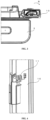
FIG. 8 , in thelocking mechanism 20, a projectingportion 23 is provided in thepost-side locking portion 21. The interference is caused by rotation of thepost-side locking portion 21 in a gap between thepost-side locking portion 21 and the door-side locking portion 22. When the gap has a size equal to or larger than a certain value, thepost-side locking portion 21 rotates greatly, and the positions of the protrudingportion 15 and theguide groove 13 do not coincide with each other. Therefore, by providing the projectingportion 23 in thepost-side locking portion 21, the gap is reduced, an angle by which themiddle post 10 can be rotated without releasing therelease mechanism 14 can be reduced, and the above-described interference can be prevented. - The projecting
portion 23 is formed to extend from thepost-side locking portion 21 towards the door-side locking portion 22. Thus, the gap between thepost-side locking portion 21 and the door-side locking portion 22 can be reduced. - In this way, by providing the projecting
portion 23 in thepost-side locking portion 21 serving as a part of theguide portion 16 used as one of the components of themiddle post 10, the kept position of themiddle post 10 can be adjusted by changing theguide portion 16 when required to be changed. Therefore, a number of components with shapes changed can be reduced. Furthermore, since theguide portion 16 is a relatively small component, the shape can be easily changed, and furthermore, an influence of the change in the shape on assembly can be reduced. - Preferably, the projecting
portion 23 is formed of a plurality of protrusions. Thus, when thefirst door 3 is in the open state and themiddle post 10 is at the first position, even when a force for rotating themiddle post 10 towards the second position is applied, the projectingportion 23 can be prevented from being easily deformed. - When the
middle post 10 is at the second position, the projectingportion 23 is located below the door-side locking portion 22. Then, when themiddle post 10 is switched from the second position to the first position, thepost-side locking portion 21 rotates while sliding relative to an upper portion of the projectingportion 23 and a lower portion of the door-side locking portion 22. Or, when the protrudingportion 15 is engaged with theguide groove 13 and pushed downwards to rotate themiddle post 10, the projectingportion 23 does not slide along with the door-side locking portion 22, and when the engagement between the protrudingportion 15 and theguide groove 13 is released, the protrudingportion 15 is released from downward pushing and slides upwards by the compression coil spring 19. - At this point, in the presence of interference, even when the
middle post 10 is switched to the first position, therelease mechanism 14 is kept released, and the protrudingportion 15 may not smoothly return to the specified position; the interference is friction caused by contact between the door-side locking portion 22 and the projectingportion 23 slightly before the switching to the first position, or contact between the door-side locking portion 22 and the projectingportion 23 during sliding. In this case, themiddle post 10 can be easily switched to the second position in the state where thefirst door 3 is opened. Furthermore, in the case of a shape in which the interference occurs, interference occurs also during switching from the first position to the second position, and when thefirst door 3 is closed, therelease mechanism 14 is not normally released, and thefirst door 3 may not be closed. Therefore, the projectingportion 23 is preferably shaped to allow therelease mechanism 14 to operate smoothly (that is, therelease mechanism 14 is released smoothly, or the release of therelease mechanism 14 is canceled smoothly). For example, as shown inFIG. 8 , preferably, at least an upper corner facing the door-side locking portion 22 is chamfered. Thus, the above-described interference can be reduced, and smooth switching from the second position to the first position or from the first position to the second position can be allowed. - The present invention is not limited to the illustrated embodiments, and various improvements and design changes can be made without departing from the scope of the present invention.
- As described above, the present invention can provide the refrigerator which can reduce the force required to close the door and can hold the required position when the door is closed, and therefore, the solution can be preferably applied to the industrial field of the refrigerator.
-
- 1
- refrigerator
- 2
- refrigerator body
- 3
- first door
- 4
- second door
- 5
- storage chamber
- 10
- middle post
- 12
- guide mechanism
- 13
- guide groove
- 14
- release mechanism
- 20
- locking mechanism
- 21
- post-side locking portion
- 22
- door-side locking portion
- 23
- projecting portion
Claims (10)
- A refrigerator, having side-by-side doors comprising a first door and a second door,wherein the first door has a rotatably provided middle post,the middle post has a locking mechanism for preventing rotation of the middle post,the locking mechanism has a release mechanism for releasing locking,the middle post is switched between a first position where the middle post is located when the first door is opened and a second position where the middle post is located when the first door is closed by opening and closing the first door, and the locking mechanism is released by the release mechanism during rotation from the first position to the second position, thus performing switching,the locking mechanism has a projecting portion, and the projecting portion reduces an amount of rotation of the middle post when the middle post is in the first position and the release mechanism is not released.
- The refrigerator according to claim 1,wherein the locking mechanism further has a post-side locking portion,the post-side locking portion comes into contact with a door-side locking portion provided on the first door when the middle post rotates, thereby preventing the rotation of the middle post,the projecting portion is configured to extend to a gap between the post-side locking portion and the door-side locking portion.
- The refrigerator according to claim 2, wherein an upper corner of the projecting portion facing the door-side locking portion has a chamfered shape.
- The refrigerator according to claim 2, wherein the projecting portion is formed to extend from the post-side locking portion towards the door-side locking portion.
- The refrigerator according to claim 2, wherein the projecting portion is formed of a plurality of protrusions.
- The refrigerator according to claim 1, wherein the middle post is kept at the first position by a torsion spiral spring when the first door is opened.
- The refrigerator according to claim 2, wherein the projecting portion is located below the door-side locking portion when the middle post is at the second position, and the post-side locking portion rotates while sliding relative to an upper portion of the projecting portion and a lower portion of the door-side locking portion when the middle post is switched from the second position to the first position.
- The refrigerator according to claim 2, wherein the refrigerator has a refrigerator body and a guide mechanism mounted to the refrigerator body, and when the middle post is engaged with the guide mechanism, the post-side locking portion moves downwards.
- The refrigerator according to claim 8, wherein the guide mechanism is provided therein with a guide groove, the release mechanism has a vertically slidable protruding portion protruding to an upper portion of the middle post, and a guide portion integrated with the protruding portion to slide, the guide portion has the locking mechanism, and when the protruding portion is engaged with the guide groove, the protruding portion is pushed downwards, and the guide portion and the post-side locking portion move downwards.
- The refrigerator according to claim 9, wherein the guide portion is mounted to a compression coil spring, and when the engagement between the protruding portion and the guide groove is released, the compression coil spring drives the guide portion and the protruding portion to slide upwards.
Applications Claiming Priority (2)
| Application Number | Priority Date | Filing Date | Title |
|---|---|---|---|
| JP2020146170A JP7542849B2 (en) | 2020-08-31 | 2020-08-31 | refrigerator |
| PCT/CN2021/115376 WO2022042725A1 (en) | 2020-08-31 | 2021-08-30 | Refrigerator |
Publications (3)
| Publication Number | Publication Date |
|---|---|
| EP4187182A1 true EP4187182A1 (en) | 2023-05-31 |
| EP4187182A4 EP4187182A4 (en) | 2023-12-27 |
| EP4187182B1 EP4187182B1 (en) | 2025-11-05 |
Family
ID=80354691
Family Applications (1)
| Application Number | Title | Priority Date | Filing Date |
|---|---|---|---|
| EP21860557.4A Active EP4187182B1 (en) | 2020-08-31 | 2021-08-30 | Refrigerator |
Country Status (6)
| Country | Link |
|---|---|
| US (1) | US12339056B2 (en) |
| EP (1) | EP4187182B1 (en) |
| JP (1) | JP7542849B2 (en) |
| CN (1) | CN116097055B (en) |
| AU (1) | AU2021330088B2 (en) |
| WO (1) | WO2022042725A1 (en) |
Family Cites Families (20)
| Publication number | Priority date | Publication date | Assignee | Title |
|---|---|---|---|---|
| CA2438766C (en) * | 2003-08-29 | 2008-12-30 | Maytag Corporation | Refrigerator incorporating french doors with rotating mullion bar |
| CN101135531B (en) * | 2006-08-28 | 2010-10-13 | 海尔集团公司 | Refrigerator with side-by-side door with movable center beam |
| CN101865592B (en) * | 2010-06-21 | 2012-11-28 | 广东奥马电器股份有限公司 | Left-right side-by-side refrigerator sealing center sill structure |
| CN103185441B (en) * | 2011-12-30 | 2016-09-07 | 博西华电器(江苏)有限公司 | Electric refrigerator including two doors |
| EP2741034B1 (en) * | 2012-12-10 | 2020-06-10 | LG Electronics, Inc. | Refrigerator |
| CN203572131U (en) * | 2013-07-31 | 2014-04-30 | 博西华电器(江苏)有限公司 | Refrigerator |
| CN104776676A (en) | 2015-05-04 | 2015-07-15 | 青岛海尔股份有限公司 | Middle beam structure for refrigerator and refrigerator comprising middle beam structure |
| CN105737489B (en) | 2016-04-18 | 2018-10-26 | 海信容声(广东)冰箱有限公司 | A kind of side by side combination refrigerator with flip beam |
| CN106352651B (en) | 2016-08-19 | 2019-08-02 | 海信(山东)冰箱有限公司 | A side-by-side refrigerator |
| CN206469575U (en) * | 2017-01-09 | 2017-09-05 | 南京创维家用电器有限公司 | A kind of door turns beam and its refrigerator |
| KR102705438B1 (en) * | 2017-01-23 | 2024-09-11 | 삼성전자주식회사 | Refrigerator |
| CN107664374B (en) * | 2017-10-13 | 2024-01-12 | 海尔智家股份有限公司 | A center beam structure and a refrigerator including the same |
| US10837695B2 (en) * | 2017-12-04 | 2020-11-17 | Electrolux Home Products, Inc. | Refrigerator assembly |
| JP6681555B2 (en) | 2018-08-24 | 2020-04-15 | パナソニックIpマネジメント株式会社 | refrigerator |
| CN208901713U (en) | 2018-08-28 | 2019-05-24 | 广东格兰仕集团有限公司 | The flip beam locking structure of refrigerator |
| US10907880B2 (en) * | 2018-12-17 | 2021-02-02 | Whirlpool Corporation | Refrigerator mullion assembly with anti-condensation features |
| KR102922660B1 (en) * | 2019-05-17 | 2026-02-05 | 삼성전자주식회사 | Refrigrator |
| US10995977B2 (en) * | 2019-08-28 | 2021-05-04 | Whirlpool Corporation | Mullion hinge assembly |
| CN114383351B (en) * | 2020-10-19 | 2022-11-18 | 合肥海尔电冰箱有限公司 | Refrigerator |
| US12078408B2 (en) * | 2022-10-26 | 2024-09-03 | Whirlpool Corporation | Refrigerator and mullion for a refrigerator |
-
2020
- 2020-08-31 JP JP2020146170A patent/JP7542849B2/en active Active
-
2021
- 2021-08-30 WO PCT/CN2021/115376 patent/WO2022042725A1/en not_active Ceased
- 2021-08-30 CN CN202180053416.8A patent/CN116097055B/en active Active
- 2021-08-30 EP EP21860557.4A patent/EP4187182B1/en active Active
- 2021-08-30 US US18/023,723 patent/US12339056B2/en active Active
- 2021-08-30 AU AU2021330088A patent/AU2021330088B2/en active Active
Also Published As
| Publication number | Publication date |
|---|---|
| EP4187182A4 (en) | 2023-12-27 |
| EP4187182B1 (en) | 2025-11-05 |
| US12339056B2 (en) | 2025-06-24 |
| JP7542849B2 (en) | 2024-09-02 |
| WO2022042725A1 (en) | 2022-03-03 |
| US20230341171A1 (en) | 2023-10-26 |
| JP2022041127A (en) | 2022-03-11 |
| CN116097055A (en) | 2023-05-09 |
| AU2021330088A1 (en) | 2023-03-23 |
| AU2021330088B2 (en) | 2024-05-09 |
| CN116097055B (en) | 2024-07-16 |
Similar Documents
| Publication | Publication Date | Title |
|---|---|---|
| US20240368929A1 (en) | Hinge assembly and refrigerator having the same | |
| US12055335B2 (en) | Hinge assembly with baffle and refrigerator having the same | |
| AU2020317147B2 (en) | Hinge assembly having decorative sheet, and refrigerator having hinge assembly | |
| WO2021037098A1 (en) | Refrigerator with wiring module | |
| WO2021037096A1 (en) | Refrigerator provided with switchable hinge assembly | |
| WO2021037095A1 (en) | Refrigerator with movable hinge assembly | |
| AU2020319114B2 (en) | Hinge assembly having movable plate, and refrigerator having hinge assembly | |
| US20060232176A1 (en) | Door opening and closing device for refrigerator | |
| EP3401626B1 (en) | Refrigerator | |
| EP4088170B1 (en) | Hinge with translatable axis | |
| CN218495583U (en) | Refrigerator with a door | |
| EP4187182B1 (en) | Refrigerator | |
| CN222703595U (en) | Refrigerator with a refrigerator body | |
| KR102592647B1 (en) | Refrigerator | |
| EP3401625B1 (en) | Refrigerator | |
| CN114136042B (en) | Refrigerator with lockable flip beam | |
| CN222335759U (en) | Refrigerator with a refrigerator body | |
| CN222335747U (en) | refrigerator | |
| CN222526083U (en) | Refrigerator door buffering structure and refrigerator | |
| CN222335754U (en) | Refrigerator with a refrigerator body | |
| CN114096181A (en) | Furniture component | |
| CN222335751U (en) | Refrigerator with a refrigerator body | |
| CN222418123U (en) | refrigerator | |
| WO2021037108A1 (en) | Refrigerator capable of inward shifting center of gravity | |
| CN116411757A (en) | Hinge and refrigeration device with the hinge |
Legal Events
| Date | Code | Title | Description |
|---|---|---|---|
| STAA | Information on the status of an ep patent application or granted ep patent |
Free format text: STATUS: THE INTERNATIONAL PUBLICATION HAS BEEN MADE |
|
| PUAI | Public reference made under article 153(3) epc to a published international application that has entered the european phase |
Free format text: ORIGINAL CODE: 0009012 |
|
| STAA | Information on the status of an ep patent application or granted ep patent |
Free format text: STATUS: REQUEST FOR EXAMINATION WAS MADE |
|
| 17P | Request for examination filed |
Effective date: 20230224 |
|
| AK | Designated contracting states |
Kind code of ref document: A1 Designated state(s): AL AT BE BG CH CY CZ DE DK EE ES FI FR GB GR HR HU IE IS IT LI LT LU LV MC MK MT NL NO PL PT RO RS SE SI SK SM TR |
|
| DAV | Request for validation of the european patent (deleted) | ||
| DAX | Request for extension of the european patent (deleted) | ||
| A4 | Supplementary search report drawn up and despatched |
Effective date: 20231128 |
|
| RIC1 | Information provided on ipc code assigned before grant |
Ipc: F25D 23/02 20060101ALI20231122BHEP Ipc: F25D 11/02 20060101AFI20231122BHEP |
|
| GRAP | Despatch of communication of intention to grant a patent |
Free format text: ORIGINAL CODE: EPIDOSNIGR1 |
|
| STAA | Information on the status of an ep patent application or granted ep patent |
Free format text: STATUS: GRANT OF PATENT IS INTENDED |
|
| INTG | Intention to grant announced |
Effective date: 20250701 |
|
| RIN1 | Information on inventor provided before grant (corrected) |
Inventor name: SHITARA, SHINSUKE |
|
| GRAS | Grant fee paid |
Free format text: ORIGINAL CODE: EPIDOSNIGR3 |
|
| GRAA | (expected) grant |
Free format text: ORIGINAL CODE: 0009210 |
|
| STAA | Information on the status of an ep patent application or granted ep patent |
Free format text: STATUS: THE PATENT HAS BEEN GRANTED |
|
| AK | Designated contracting states |
Kind code of ref document: B1 Designated state(s): AL AT BE BG CH CY CZ DE DK EE ES FI FR GB GR HR HU IE IS IT LI LT LU LV MC MK MT NL NO PL PT RO RS SE SI SK SM TR |
|
| REG | Reference to a national code |
Ref country code: CH Ref legal event code: F10 Free format text: ST27 STATUS EVENT CODE: U-0-0-F10-F00 (AS PROVIDED BY THE NATIONAL OFFICE) Effective date: 20251105 Ref country code: GB Ref legal event code: FG4D |
|
| REG | Reference to a national code |
Ref country code: DE Ref legal event code: R096 Ref document number: 602021041967 Country of ref document: DE |
|
| REG | Reference to a national code |
Ref country code: IE Ref legal event code: FG4D |
|
| REG | Reference to a national code |
Ref country code: NL Ref legal event code: MP Effective date: 20251105 |
|
| PG25 | Lapsed in a contracting state [announced via postgrant information from national office to epo] |
Ref country code: ES Free format text: LAPSE BECAUSE OF FAILURE TO SUBMIT A TRANSLATION OF THE DESCRIPTION OR TO PAY THE FEE WITHIN THE PRESCRIBED TIME-LIMIT Effective date: 20251105 |
|
| REG | Reference to a national code |
Ref country code: LT Ref legal event code: MG9D |
|
| PG25 | Lapsed in a contracting state [announced via postgrant information from national office to epo] |
Ref country code: NO Free format text: LAPSE BECAUSE OF FAILURE TO SUBMIT A TRANSLATION OF THE DESCRIPTION OR TO PAY THE FEE WITHIN THE PRESCRIBED TIME-LIMIT Effective date: 20260205 |
|
| PG25 | Lapsed in a contracting state [announced via postgrant information from national office to epo] |
Ref country code: HR Free format text: LAPSE BECAUSE OF FAILURE TO SUBMIT A TRANSLATION OF THE DESCRIPTION OR TO PAY THE FEE WITHIN THE PRESCRIBED TIME-LIMIT Effective date: 20251105 Ref country code: AT Free format text: LAPSE BECAUSE OF FAILURE TO SUBMIT A TRANSLATION OF THE DESCRIPTION OR TO PAY THE FEE WITHIN THE PRESCRIBED TIME-LIMIT Effective date: 20251105 Ref country code: FI Free format text: LAPSE BECAUSE OF FAILURE TO SUBMIT A TRANSLATION OF THE DESCRIPTION OR TO PAY THE FEE WITHIN THE PRESCRIBED TIME-LIMIT Effective date: 20251105 |
|
| REG | Reference to a national code |
Ref country code: AT Ref legal event code: MK05 Ref document number: 1854746 Country of ref document: AT Kind code of ref document: T Effective date: 20251105 |
|
| PG25 | Lapsed in a contracting state [announced via postgrant information from national office to epo] |
Ref country code: NL Free format text: LAPSE BECAUSE OF FAILURE TO SUBMIT A TRANSLATION OF THE DESCRIPTION OR TO PAY THE FEE WITHIN THE PRESCRIBED TIME-LIMIT Effective date: 20251105 |
|
| PG25 | Lapsed in a contracting state [announced via postgrant information from national office to epo] |
Ref country code: RS Free format text: LAPSE BECAUSE OF FAILURE TO SUBMIT A TRANSLATION OF THE DESCRIPTION OR TO PAY THE FEE WITHIN THE PRESCRIBED TIME-LIMIT Effective date: 20260205 |
|
| PG25 | Lapsed in a contracting state [announced via postgrant information from national office to epo] |
Ref country code: IS Free format text: LAPSE BECAUSE OF FAILURE TO SUBMIT A TRANSLATION OF THE DESCRIPTION OR TO PAY THE FEE WITHIN THE PRESCRIBED TIME-LIMIT Effective date: 20260305 |
|
| PG25 | Lapsed in a contracting state [announced via postgrant information from national office to epo] |
Ref country code: PT Free format text: LAPSE BECAUSE OF FAILURE TO SUBMIT A TRANSLATION OF THE DESCRIPTION OR TO PAY THE FEE WITHIN THE PRESCRIBED TIME-LIMIT Effective date: 20260305 |
|
| PG25 | Lapsed in a contracting state [announced via postgrant information from national office to epo] |
Ref country code: PL Free format text: LAPSE BECAUSE OF FAILURE TO SUBMIT A TRANSLATION OF THE DESCRIPTION OR TO PAY THE FEE WITHIN THE PRESCRIBED TIME-LIMIT Effective date: 20251105 |
|
| PG25 | Lapsed in a contracting state [announced via postgrant information from national office to epo] |
Ref country code: LV Free format text: LAPSE BECAUSE OF FAILURE TO SUBMIT A TRANSLATION OF THE DESCRIPTION OR TO PAY THE FEE WITHIN THE PRESCRIBED TIME-LIMIT Effective date: 20251105 |
|
| PG25 | Lapsed in a contracting state [announced via postgrant information from national office to epo] |
Ref country code: BG Free format text: LAPSE BECAUSE OF FAILURE TO SUBMIT A TRANSLATION OF THE DESCRIPTION OR TO PAY THE FEE WITHIN THE PRESCRIBED TIME-LIMIT Effective date: 20251105 |