EP4187181B1 - Storage device - Google Patents
Storage device Download PDFInfo
- Publication number
- EP4187181B1 EP4187181B1 EP21865892.0A EP21865892A EP4187181B1 EP 4187181 B1 EP4187181 B1 EP 4187181B1 EP 21865892 A EP21865892 A EP 21865892A EP 4187181 B1 EP4187181 B1 EP 4187181B1
- Authority
- EP
- European Patent Office
- Prior art keywords
- housing
- box body
- automatic door
- opening
- storage device
- Prior art date
- Legal status (The legal status is an assumption and is not a legal conclusion. Google has not performed a legal analysis and makes no representation as to the accuracy of the status listed.)
- Active
Links
Images




Classifications
-
- F—MECHANICAL ENGINEERING; LIGHTING; HEATING; WEAPONS; BLASTING
- F25—REFRIGERATION OR COOLING; COMBINED HEATING AND REFRIGERATION SYSTEMS; HEAT PUMP SYSTEMS; MANUFACTURE OR STORAGE OF ICE; LIQUEFACTION SOLIDIFICATION OF GASES
- F25D—REFRIGERATORS; COLD ROOMS; ICE-BOXES; COOLING OR FREEZING APPARATUS NOT OTHERWISE PROVIDED FOR
- F25D11/00—Self-contained movable devices, e.g. domestic refrigerators
-
- E—FIXED CONSTRUCTIONS
- E05—LOCKS; KEYS; WINDOW OR DOOR FITTINGS; SAFES
- E05F—DEVICES FOR MOVING WINGS INTO OPEN OR CLOSED POSITION; CHECKS FOR WINGS; WING FITTINGS NOT OTHERWISE PROVIDED FOR, CONCERNED WITH THE FUNCTIONING OF THE WING
- E05F15/00—Power-operated mechanisms for wings
- E05F15/60—Power-operated mechanisms for wings using electrical actuators
- E05F15/603—Power-operated mechanisms for wings using electrical actuators using rotary electromotors
- E05F15/611—Power-operated mechanisms for wings using electrical actuators using rotary electromotors for swinging wings
-
- E—FIXED CONSTRUCTIONS
- E05—LOCKS; KEYS; WINDOW OR DOOR FITTINGS; SAFES
- E05F—DEVICES FOR MOVING WINGS INTO OPEN OR CLOSED POSITION; CHECKS FOR WINGS; WING FITTINGS NOT OTHERWISE PROVIDED FOR, CONCERNED WITH THE FUNCTIONING OF THE WING
- E05F5/00—Braking devices, e.g. checks; Stops; Buffers
- E05F5/06—Buffers or stops limiting opening of swinging wings, e.g. floor or wall stops
-
- F—MECHANICAL ENGINEERING; LIGHTING; HEATING; WEAPONS; BLASTING
- F25—REFRIGERATION OR COOLING; COMBINED HEATING AND REFRIGERATION SYSTEMS; HEAT PUMP SYSTEMS; MANUFACTURE OR STORAGE OF ICE; LIQUEFACTION SOLIDIFICATION OF GASES
- F25D—REFRIGERATORS; COLD ROOMS; ICE-BOXES; COOLING OR FREEZING APPARATUS NOT OTHERWISE PROVIDED FOR
- F25D23/00—General constructional features
- F25D23/02—Doors; Covers
-
- E—FIXED CONSTRUCTIONS
- E05—LOCKS; KEYS; WINDOW OR DOOR FITTINGS; SAFES
- E05Y—INDEXING SCHEME ASSOCIATED WITH SUBCLASSES E05D AND E05F, RELATING TO CONSTRUCTION ELEMENTS, ELECTRIC CONTROL, POWER SUPPLY, POWER SIGNAL OR TRANSMISSION, USER INTERFACES, MOUNTING OR COUPLING, DETAILS, ACCESSORIES, AUXILIARY OPERATIONS NOT OTHERWISE PROVIDED FOR, APPLICATION THEREOF
- E05Y2201/00—Constructional elements; Accessories therefor
- E05Y2201/10—Covers; Housings
-
- E—FIXED CONSTRUCTIONS
- E05—LOCKS; KEYS; WINDOW OR DOOR FITTINGS; SAFES
- E05Y—INDEXING SCHEME ASSOCIATED WITH SUBCLASSES E05D AND E05F, RELATING TO CONSTRUCTION ELEMENTS, ELECTRIC CONTROL, POWER SUPPLY, POWER SIGNAL OR TRANSMISSION, USER INTERFACES, MOUNTING OR COUPLING, DETAILS, ACCESSORIES, AUXILIARY OPERATIONS NOT OTHERWISE PROVIDED FOR, APPLICATION THEREOF
- E05Y2201/00—Constructional elements; Accessories therefor
- E05Y2201/10—Covers; Housings
- E05Y2201/11—Covers
-
- E—FIXED CONSTRUCTIONS
- E05—LOCKS; KEYS; WINDOW OR DOOR FITTINGS; SAFES
- E05Y—INDEXING SCHEME ASSOCIATED WITH SUBCLASSES E05D AND E05F, RELATING TO CONSTRUCTION ELEMENTS, ELECTRIC CONTROL, POWER SUPPLY, POWER SIGNAL OR TRANSMISSION, USER INTERFACES, MOUNTING OR COUPLING, DETAILS, ACCESSORIES, AUXILIARY OPERATIONS NOT OTHERWISE PROVIDED FOR, APPLICATION THEREOF
- E05Y2201/00—Constructional elements; Accessories therefor
- E05Y2201/40—Motors; Magnets; Springs; Weights; Accessories therefor
- E05Y2201/404—Function thereof
- E05Y2201/422—Function thereof for opening
- E05Y2201/426—Function thereof for opening for the initial opening movement
-
- E—FIXED CONSTRUCTIONS
- E05—LOCKS; KEYS; WINDOW OR DOOR FITTINGS; SAFES
- E05Y—INDEXING SCHEME ASSOCIATED WITH SUBCLASSES E05D AND E05F, RELATING TO CONSTRUCTION ELEMENTS, ELECTRIC CONTROL, POWER SUPPLY, POWER SIGNAL OR TRANSMISSION, USER INTERFACES, MOUNTING OR COUPLING, DETAILS, ACCESSORIES, AUXILIARY OPERATIONS NOT OTHERWISE PROVIDED FOR, APPLICATION THEREOF
- E05Y2201/00—Constructional elements; Accessories therefor
- E05Y2201/60—Suspension or transmission members; Accessories therefor
- E05Y2201/622—Suspension or transmission members elements
- E05Y2201/624—Arms
-
- E—FIXED CONSTRUCTIONS
- E05—LOCKS; KEYS; WINDOW OR DOOR FITTINGS; SAFES
- E05Y—INDEXING SCHEME ASSOCIATED WITH SUBCLASSES E05D AND E05F, RELATING TO CONSTRUCTION ELEMENTS, ELECTRIC CONTROL, POWER SUPPLY, POWER SIGNAL OR TRANSMISSION, USER INTERFACES, MOUNTING OR COUPLING, DETAILS, ACCESSORIES, AUXILIARY OPERATIONS NOT OTHERWISE PROVIDED FOR, APPLICATION THEREOF
- E05Y2600/00—Mounting or coupling arrangements for elements provided for in this subclass
- E05Y2600/40—Mounting location; Visibility of the elements
- E05Y2600/45—Mounting location; Visibility of the elements in or on the fixed frame
-
- E—FIXED CONSTRUCTIONS
- E05—LOCKS; KEYS; WINDOW OR DOOR FITTINGS; SAFES
- E05Y—INDEXING SCHEME ASSOCIATED WITH SUBCLASSES E05D AND E05F, RELATING TO CONSTRUCTION ELEMENTS, ELECTRIC CONTROL, POWER SUPPLY, POWER SIGNAL OR TRANSMISSION, USER INTERFACES, MOUNTING OR COUPLING, DETAILS, ACCESSORIES, AUXILIARY OPERATIONS NOT OTHERWISE PROVIDED FOR, APPLICATION THEREOF
- E05Y2600/00—Mounting or coupling arrangements for elements provided for in this subclass
- E05Y2600/60—Mounting or coupling members; Accessories therefor
- E05Y2600/61—Threaded members
-
- E—FIXED CONSTRUCTIONS
- E05—LOCKS; KEYS; WINDOW OR DOOR FITTINGS; SAFES
- E05Y—INDEXING SCHEME ASSOCIATED WITH SUBCLASSES E05D AND E05F, RELATING TO CONSTRUCTION ELEMENTS, ELECTRIC CONTROL, POWER SUPPLY, POWER SIGNAL OR TRANSMISSION, USER INTERFACES, MOUNTING OR COUPLING, DETAILS, ACCESSORIES, AUXILIARY OPERATIONS NOT OTHERWISE PROVIDED FOR, APPLICATION THEREOF
- E05Y2600/00—Mounting or coupling arrangements for elements provided for in this subclass
- E05Y2600/60—Mounting or coupling members; Accessories therefor
- E05Y2600/62—Bolts
-
- E—FIXED CONSTRUCTIONS
- E05—LOCKS; KEYS; WINDOW OR DOOR FITTINGS; SAFES
- E05Y—INDEXING SCHEME ASSOCIATED WITH SUBCLASSES E05D AND E05F, RELATING TO CONSTRUCTION ELEMENTS, ELECTRIC CONTROL, POWER SUPPLY, POWER SIGNAL OR TRANSMISSION, USER INTERFACES, MOUNTING OR COUPLING, DETAILS, ACCESSORIES, AUXILIARY OPERATIONS NOT OTHERWISE PROVIDED FOR, APPLICATION THEREOF
- E05Y2900/00—Application of doors, windows, wings or fittings thereof
- E05Y2900/30—Application of doors, windows, wings or fittings thereof for domestic appliances
- E05Y2900/31—Application of doors, windows, wings or fittings thereof for domestic appliances for refrigerators
-
- F—MECHANICAL ENGINEERING; LIGHTING; HEATING; WEAPONS; BLASTING
- F25—REFRIGERATION OR COOLING; COMBINED HEATING AND REFRIGERATION SYSTEMS; HEAT PUMP SYSTEMS; MANUFACTURE OR STORAGE OF ICE; LIQUEFACTION SOLIDIFICATION OF GASES
- F25D—REFRIGERATORS; COLD ROOMS; ICE-BOXES; COOLING OR FREEZING APPARATUS NOT OTHERWISE PROVIDED FOR
- F25D23/00—General constructional features
- F25D23/02—Doors; Covers
- F25D23/028—Details
-
- F—MECHANICAL ENGINEERING; LIGHTING; HEATING; WEAPONS; BLASTING
- F25—REFRIGERATION OR COOLING; COMBINED HEATING AND REFRIGERATION SYSTEMS; HEAT PUMP SYSTEMS; MANUFACTURE OR STORAGE OF ICE; LIQUEFACTION SOLIDIFICATION OF GASES
- F25D—REFRIGERATORS; COLD ROOMS; ICE-BOXES; COOLING OR FREEZING APPARATUS NOT OTHERWISE PROVIDED FOR
- F25D2323/00—General constructional features not provided for in other groups of this subclass
- F25D2323/02—Details of doors or covers not otherwise covered
- F25D2323/021—French doors
Definitions
- the present invention relates to a storage device, and particularly to a storage device with an automatic door-opening device.
- a large refrigerator has a heavy door body, a door gasket has a large suction force, and in order to solve the problem that a user cannot open the door body easily, in the prior art, an automatic door-opening device is provided on a box body of the refrigerator to help the user open the door body.
- fixation of the automatic door-opening device requires that a mounting box is preset before the box body is foamed, and then, the automatic door-opening device is fixed in the mounting box.
- the arrangement of the mounting box reduces the thickness of a foamed heat insulation layer of the refrigerator to reduce the heat insulation performance of the box body, and requires that holes are punched in an outer box of the box body in advance to position and mount the automatic door-opening device and the mounting box, the process is complex, and the production cost is high.
- it is desirable to provide a storage device with an automatic door-opening device which has a simple process and a stable and reliable structure. Relevant prior art can be found in US 2008/083243A1 and US2019/169910A1 .
- An object of the present invention is to overcome at least one of the technical drawbacks of the prior art and provide a storage device with an automatic door-opening device.
- a further object of the present invention is to make a process simple.
- Another object of the present invention is to improve the stability of the automatic door-opening device.
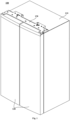
- Fig. 1 is a schematic isometric diagram of a storage device 100 according to an embodiment of the present invention
- Fig. 2 is a schematic partial sectional diagram of the storage device 100 shown in Fig. 1 taken along a vertical plane
- Fig. 3 is a schematic enlarged diagram of region A in Fig. 2 .
- the storage device 100 includes a box body 110 defining at least one storage compartment, at least one door body 120 for opening and closing the at least one storage compartment, and an automatic door-opening assembly for opening the at least one door body 120.
- the storage device 100 includes only two door bodies 120 distributed in a transverse direction.
- the automatic door-opening assembly is provided above the storage device 100 and used for automatically opening the two door bodies 120.
- the storage device 100 may include two door bodies hinged to an upper portion of the box body 110 and two door bodies hinged to a lower portion of the box body 110.
- Automatic door-opening assemblies can be provided above and below the storage device 100 respectively to automatically open the four door bodies.
- the automatic door-opening assembly includes a housing 130 and at least one automatic door-opening device 140.
- two automatic door-opening devices 140 may be provided to open the two door bodies 120 respectively.
- the automatic door-opening device 140 may include a motor 142 for providing a driving force for opening the door body 120, and a jacking rod in drive connection with the motor 142 and movable back and forth relative to the box body 110.
- each automatic door-opening device 140 may be at least partially provided on a side of the housing 130 close to the box body 110 and fixedly connected to the housing 130.
- the housing 130 can be configured to be fixedly connected to the box body 110 to indirectly fix the automatic door-opening device 140 to the box body 110, and compared with the solution that a mounting box is preset before the box body 110 is foamed, and then, the automatic door-opening device 140 is fixed in the mounting box, assembling is simple, a pre-perforation operation is avoided, the solution can also be applicable to storage devices 100 with different widths, the universality is strong, the influence of the production line process is small, and the production cost is reduced.
- the automatic door-opening assembly further includes a plurality of fasteners 150.
- the plurality of fasteners 150 are configured to fixedly connect the automatic door-opening device 140 to the housing 130, and to fixedly connect the housing 130 to the box body 110. That is, some fasteners 150 may be used to fixedly connect the automatic door-opening device 140 to the housing 130, and some fasteners 150 may be used to fixedly connect the housing 130 to the box body 110.
- the automatic door-opening device 140 is fixed to the housing 130 by the fasteners 150 in a direction away from the box body 110, so as to more firmly mount the automatic door-opening device 140.
- the fasteners 150 fix the automatic door-opening device 140 to the housing 130 from bottom to top.
- the housing 130 is fixed to the box body 110 by the fasteners 150 in a direction close to the box body 110.
- the fasteners 150 fix the housing 130 to the box body 110 from top to bottom.
- each automatic door-opening device 140 is provided with a plurality of through holes 141.
- the housing 130 is provided with a plurality of connecting protrusions 131 extending towards the box body 110, and each connecting protrusion 131 is configured to penetrate through one through hole 141.
- the fasteners 150 are configured to be fastened to the connecting protrusions 131 to improve the reliability of the automatic door-opening device 140.
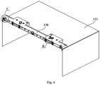
- Fig. 4 is a schematic partial sectional diagram of the storage device 100 shown in Fig. 1 taken along another vertical plane;
- Fig. 5 is a schematic enlarged diagram of region B in Fig. 4 .
- the automatic door-opening assembly may further include a plurality of limiting clamping sheets 170.
- the plurality of limiting clamping sheets 170 may be clamped and fixed at end portions, close to the box body 110, of the plurality of connecting protrusions 131 fixedly connected with the box body 110, and limit the motion of the at least one automatic door-opening device 140 in the axial direction of the through hole 141, so as to prevent the automatic door-opening device 140 from deflecting and affecting functions in the mounting process of the housing 130.
- the limiting clamping sheet 170 may be annular and have a wedge-shaped mounting opening.
- the end portion of the connecting protrusion 131 close to the box body 110 may be provided with a mounting groove, and the limiting clamping sheet 170 may be clamped and fixed in the mounting groove through the mounting opening.
- the fastener 150 may directly limit the motion of the automatic door-opening device 140 and the housing 130 in the axial direction of the through hole 141 by a head thereof. In some other embodiments, the fastener 150 may limit the motion of the automatic door-opening device 140 and the housing 130 in the axial direction of the through hole 141 by a gasket 155.
- Fig. 6 is a schematic isometric diagram of an elastic washer 160 in Figs. 3 and 5 .
- the automatic door-opening assembly may further include a plurality of elastic washers 160.
- the plurality of elastic washers 160 may be provided between the plurality of connecting protrusions 131 and the plurality of through holes 141 respectively, so as to improve the stability of the automatic door-opening device 140 and prevent the fasteners 150 from being loosened.
- Each elastic washer 160 may include two damping portions 161 and one connecting portion 162.
- the two damping portions 161 may be provided at the peripheral edge of the through hole 141 close to the box body 110 and the peripheral edge of the through hole close to the housing 130 respectively.
- the connecting portion 162 may be provided in the through hole 141 and connected with the two damping portions 161.
- the elastic washer 160 may be provided between the housing 130 and the gasket 155.
- the elastic washer 160 may be provided between the housing 130 and the limiting clamping sheet 170, such that the automatic door-opening assembly has high reliability both during transportation and after mounted to the box body 110.
- each elastic washer 160 may further include a plurality of spherical protrusions 163.
- the plurality of spherical protrusions 163 may be provided on the two damping portions 161 respectively, and protrude in a direction away from the connecting portion 162, so as to reduce a contact area between the elastic washer 160 and the housing 130 or the limiting clamping sheet 170 or the gasket 155, and improve the damping effect.
- some spherical protrusions 163 are in a compressed state.
- At least one avoiding hole 132 may be formed on a side wall of the housing 130 away from the box body 110.
- Each motor 142 may be partially provided within one avoiding hole 132 to reduce the space occupied by the automatic door-opening assembly in the vertical direction.
- the automatic door-opening assembly may further include at least one sealing ring 180.
- the at least one sealing ring 180 may be provided between the at least one avoiding hole 132 and the at least one motor 142 respectively. That is, each avoiding hole 132 is correspondingly provided with one sealing ring 180 to prevent dust from falling into the housing 130.
- the storage device 100 may be a refrigerator.
- the box body 110 may include an outer box 111, a liner, and a heat insulation layer provided between the outer box 111 and the liner to reduce cold leakage.
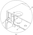
- Fig. 7 is a schematic enlarged diagram of region C in Fig. 4 .
- the box body 110 may further include a metal reinforcement 112 provided between the outer box 111 and the heat insulation layer.
- the housing 130 may be configured to be at least fixedly connected to the metal reinforcement 112 to improve the overall structural strength of the refrigerator and prevent the automatic door-opening assembly from being separated from the box body 110 due to a reaction force generated when the door body 120 is opened.
- the housing 130 is fixedly connected to the outer box 111, the metal reinforcement 112, and the heat insulation layer at the same time by the fasteners 150.
- the housing 130 can be configured to cover a hinge device connecting the box body 110 and the door body 120, so as to further simplify the process flow and save the cost.
- One of the metal reinforcement 112 and the housing 130 may be provided with a plurality of positioning protrusions 1121, and the other of the metal reinforcement 112 and the housing 130 may be provided with a plurality of annular protrusions 133.
- the plurality of positioning protrusions 1121 are provided in inner rings of the plurality of annular protrusions 133 respectively to limit the motion of the housing 130 in the radial direction of the annular protrusions 133, so as to position the automatic door-opening assembly, thereby avoiding that the door body 120 cannot pivot or the automatic door-opening device 140 fails.
Landscapes
- Engineering & Computer Science (AREA)
- Chemical & Material Sciences (AREA)
- Combustion & Propulsion (AREA)
- Physics & Mathematics (AREA)
- Mechanical Engineering (AREA)
- Thermal Sciences (AREA)
- General Engineering & Computer Science (AREA)
- Refrigerator Housings (AREA)
- Valve Device For Special Equipments (AREA)
- Vehicle Body Suspensions (AREA)
Description
- The present invention relates to a storage device, and particularly to a storage device with an automatic door-opening device.
- A large refrigerator has a heavy door body, a door gasket has a large suction force, and in order to solve the problem that a user cannot open the door body easily, in the prior art, an automatic door-opening device is provided on a box body of the refrigerator to help the user open the door body. However, fixation of the automatic door-opening device requires that a mounting box is preset before the box body is foamed, and then, the automatic door-opening device is fixed in the mounting box. The arrangement of the mounting box reduces the thickness of a foamed heat insulation layer of the refrigerator to reduce the heat insulation performance of the box body, and requires that holes are punched in an outer box of the box body in advance to position and mount the automatic door-opening device and the mounting box, the process is complex, and the production cost is high. In view of this, in design, it is desirable to provide a storage device with an automatic door-opening device, which has a simple process and a stable and reliable structure. Relevant prior art can be found in
US 2008/083243A1 andUS2019/169910A1 . - An object of the present invention is to overcome at least one of the technical drawbacks of the prior art and provide a storage device with an automatic door-opening device.
- A further object of the present invention is to make a process simple.
- Another object of the present invention is to improve the stability of the automatic door-opening device.
- According to the following detailed description of specific embodiments of the present invention in conjunction with drawings, those skilled in the art will better understand the aforementioned and other objects, advantages and features of the present invention. However, the claimed subject-matter is defined by independent claim 1. Further preferred embodiments are defined by the dependent claims.
- Some specific embodiments of the present invention will be described below in detail in an exemplary rather than restrictive manner with reference to the drawings. Identical reference numerals in the drawings represent identical or similar components or parts. Those skilled in the art should understand that these drawings are not necessarily drawn to scale. In the drawings:
-
Fig. 1 is a schematic isometric diagram of a storage device according to an embodiment of the present invention; -
Fig. 2 is a schematic partial sectional diagram of the storage device shown inFig. 1 taken along a vertical plane; -
Fig. 3 is a schematic enlarged diagram of region A inFig. 2 ; -
Fig. 4 is a schematic partial sectional diagram of the storage device shown inFig. 1 taken along another vertical plane; -
Fig. 5 is a schematic enlarged diagram of region B inFig. 4 ; -
Fig. 6 is a schematic isometric diagram of an elastic washer inFigs. 3 and5 ; and -
Fig. 7 is a schematic enlarged diagram of region C inFig. 4 . -
Fig. 1 is a schematic isometric diagram of astorage device 100 according to an embodiment of the present invention;Fig. 2 is a schematic partial sectional diagram of thestorage device 100 shown inFig. 1 taken along a vertical plane;Fig. 3 is a schematic enlarged diagram of region A inFig. 2 . Referring toFigs. 1 to 3 , thestorage device 100 includes abox body 110 defining at least one storage compartment, at least onedoor body 120 for opening and closing the at least one storage compartment, and an automatic door-opening assembly for opening the at least onedoor body 120. - In the illustrated embodiment, the
storage device 100 includes only twodoor bodies 120 distributed in a transverse direction. The automatic door-opening assembly is provided above thestorage device 100 and used for automatically opening the twodoor bodies 120. - In other embodiments, the
storage device 100 may include two door bodies hinged to an upper portion of thebox body 110 and two door bodies hinged to a lower portion of thebox body 110. Automatic door-opening assemblies can be provided above and below thestorage device 100 respectively to automatically open the four door bodies. - The automatic door-opening assembly includes a
housing 130 and at least one automatic door-opening device 140. In the illustrated embodiment, two automatic door-opening devices 140 may be provided to open the twodoor bodies 120 respectively. - Exemplarily, the automatic door-
opening device 140 may include amotor 142 for providing a driving force for opening thedoor body 120, and a jacking rod in drive connection with themotor 142 and movable back and forth relative to thebox body 110. - In particular, each automatic door-
opening device 140 may be at least partially provided on a side of thehousing 130 close to thebox body 110 and fixedly connected to thehousing 130. Thehousing 130 can be configured to be fixedly connected to thebox body 110 to indirectly fix the automatic door-openingdevice 140 to thebox body 110, and compared with the solution that a mounting box is preset before thebox body 110 is foamed, and then, the automatic door-openingdevice 140 is fixed in the mounting box, assembling is simple, a pre-perforation operation is avoided, the solution can also be applicable tostorage devices 100 with different widths, the universality is strong, the influence of the production line process is small, and the production cost is reduced. - The automatic door-opening assembly further includes a plurality of
fasteners 150. The plurality offasteners 150 are configured to fixedly connect the automatic door-openingdevice 140 to thehousing 130, and to fixedly connect thehousing 130 to thebox body 110. That is, somefasteners 150 may be used to fixedly connect the automatic door-opening device 140 to thehousing 130, and somefasteners 150 may be used to fixedly connect thehousing 130 to thebox body 110. - The automatic door-
opening device 140 is fixed to thehousing 130 by thefasteners 150 in a direction away from thebox body 110, so as to more firmly mount the automatic door-opening device 140. In the illustrated embodiment, thefasteners 150 fix the automatic door-openingdevice 140 to thehousing 130 from bottom to top. - The
housing 130 is fixed to thebox body 110 by thefasteners 150 in a direction close to thebox body 110. In the illustrated embodiment, thefasteners 150 fix thehousing 130 to thebox body 110 from top to bottom. - Specifically, each automatic door-
opening device 140 is provided with a plurality of throughholes 141. Thehousing 130 is provided with a plurality of connectingprotrusions 131 extending towards thebox body 110, and each connectingprotrusion 131 is configured to penetrate through one throughhole 141. Thefasteners 150 are configured to be fastened to the connectingprotrusions 131 to improve the reliability of the automatic door-openingdevice 140. -
Fig. 4 is a schematic partial sectional diagram of thestorage device 100 shown inFig. 1 taken along another vertical plane;Fig. 5 is a schematic enlarged diagram of region B inFig. 4 . Referring toFigs. 3 to 5 , the automatic door-opening assembly may further include a plurality of limitingclamping sheets 170. - The plurality of limiting
clamping sheets 170 may be clamped and fixed at end portions, close to thebox body 110, of the plurality of connectingprotrusions 131 fixedly connected with thebox body 110, and limit the motion of the at least one automatic door-opening device 140 in the axial direction of thethrough hole 141, so as to prevent the automatic door-openingdevice 140 from deflecting and affecting functions in the mounting process of thehousing 130. - The limiting
clamping sheet 170 may be annular and have a wedge-shaped mounting opening. The end portion of the connectingprotrusion 131 close to thebox body 110 may be provided with a mounting groove, and the limitingclamping sheet 170 may be clamped and fixed in the mounting groove through the mounting opening. - In some embodiments, the
fastener 150 may directly limit the motion of the automatic door-opening device 140 and thehousing 130 in the axial direction of thethrough hole 141 by a head thereof. In some other embodiments, thefastener 150 may limit the motion of the automatic door-opening device 140 and thehousing 130 in the axial direction of thethrough hole 141 by agasket 155. -
Fig. 6 is a schematic isometric diagram of anelastic washer 160 inFigs. 3 and5 . Referring toFigs. 3 ,5 and6 , in some embodiments, the automatic door-opening assembly may further include a plurality ofelastic washers 160. The plurality ofelastic washers 160 may be provided between the plurality of connectingprotrusions 131 and the plurality of throughholes 141 respectively, so as to improve the stability of the automatic door-openingdevice 140 and prevent thefasteners 150 from being loosened. - Each
elastic washer 160 may include twodamping portions 161 and one connectingportion 162. The two dampingportions 161 may be provided at the peripheral edge of the throughhole 141 close to thebox body 110 and the peripheral edge of the through hole close to thehousing 130 respectively. The connectingportion 162 may be provided in the throughhole 141 and connected with the two dampingportions 161. - For the
through hole 141 for fixedly connecting thehousing 130 and the automatic door-opening device 140, theelastic washer 160 may be provided between thehousing 130 and thegasket 155. For thethrough hole 141 for fixedly connecting thehousing 130 and thebox body 110, theelastic washer 160 may be provided between thehousing 130 and the limitingclamping sheet 170, such that the automatic door-opening assembly has high reliability both during transportation and after mounted to thebox body 110. - In some further embodiments, each
elastic washer 160 may further include a plurality ofspherical protrusions 163. The plurality ofspherical protrusions 163 may be provided on the two dampingportions 161 respectively, and protrude in a direction away from the connectingportion 162, so as to reduce a contact area between theelastic washer 160 and thehousing 130 or the limitingclamping sheet 170 or thegasket 155, and improve the damping effect. In the embodiment ofFigs. 3 and5 , somespherical protrusions 163 are in a compressed state. - Referring to
Figs. 3 and5 , at least one avoidinghole 132 may be formed on a side wall of thehousing 130 away from thebox body 110. Eachmotor 142 may be partially provided within one avoidinghole 132 to reduce the space occupied by the automatic door-opening assembly in the vertical direction. - The automatic door-opening assembly may further include at least one
sealing ring 180. The at least onesealing ring 180 may be provided between the at least one avoidinghole 132 and the at least onemotor 142 respectively. That is, each avoidinghole 132 is correspondingly provided with onesealing ring 180 to prevent dust from falling into thehousing 130. - In the present invention, the
storage device 100 may be a refrigerator. Thebox body 110 may include anouter box 111, a liner, and a heat insulation layer provided between theouter box 111 and the liner to reduce cold leakage. -
Fig. 7 is a schematic enlarged diagram of region C inFig. 4 . Referring toFigs. 5 and7 , in some embodiments, thebox body 110 may further include ametal reinforcement 112 provided between theouter box 111 and the heat insulation layer. Thehousing 130 may be configured to be at least fixedly connected to themetal reinforcement 112 to improve the overall structural strength of the refrigerator and prevent the automatic door-opening assembly from being separated from thebox body 110 due to a reaction force generated when thedoor body 120 is opened. - In the illustrated embodiment, the
housing 130 is fixedly connected to theouter box 111, themetal reinforcement 112, and the heat insulation layer at the same time by thefasteners 150. - In some embodiments, the
housing 130 can be configured to cover a hinge device connecting thebox body 110 and thedoor body 120, so as to further simplify the process flow and save the cost. - One of the
metal reinforcement 112 and thehousing 130 may be provided with a plurality ofpositioning protrusions 1121, and the other of themetal reinforcement 112 and thehousing 130 may be provided with a plurality ofannular protrusions 133. The plurality ofpositioning protrusions 1121 are provided in inner rings of the plurality ofannular protrusions 133 respectively to limit the motion of thehousing 130 in the radial direction of theannular protrusions 133, so as to position the automatic door-opening assembly, thereby avoiding that thedoor body 120 cannot pivot or the automatic door-openingdevice 140 fails.
Claims (8)
- A storage device (100), comprising:a box body (110) and at least one door body (120); andan automatic door-opening assembly for opening the at least one door body (120), the automatic door-opening assembly comprising:a housing (130) fixedly connected to the box body (110); andat least one automatic door-opening device (140), each automatic door-opening device (140) being at least partially provided on a side, close to the box body (110), of the housing (130), and fixedly connected to the housing (130), so as to fix the at least one automatic door-opening device (140), wherein the automatic door-opening assembly further comprises:a plurality of fasteners (150) configured to fixedly connect the at least one automatic door-opening device (140) to the housing (130) and to fixedly connect the housing (130) to the box body (110);the at least one automatic door-opening device (140) is fixed to the housing (130) by the fasteners (150) in a direction away from the box body (110); andthe housing (130) is fixed to the box body (110) by the fasteners (150) in a direction close to the box body (110),characterized in thateach automatic door-opening device (140) is provided with a plurality of through holes (141); andthe housing (130) is provided with a plurality of connecting protrusions (131) extending towards the box body (110), and each connecting protrusion is configured to penetrate through one through hole (141), wherein the fasteners (150) are configured to be fastened to the connecting protrusions (131).
- The storage device (100) according to claim 1, wherein the automatic door-opening assembly further comprises:
a plurality of elastic washers provided between the plurality of connecting protrusions (131) and the plurality of through holes (141) respectively; each elastic washer comprising:two damping portions provided at the peripheral edge of the through hole (141) close to the box body (110) and the peripheral edge of the through hole (141) close to the housing (130) respectively; anda connecting portion provided in the through hole (141) and connected with the two damping portions. - The storage device (100) according to claim 2, wherein each elastic washer further comprises:
a plurality of spherical protrusions provided on the two damping portions respectively and protruding in a direction away from the connecting portion. - The storage device (100) according to any one of claims 1 to 3, wherein the automatic door-opening assembly further comprises:
a plurality of limiting clamping sheets (170) which are clamped and fixed at end portions, close to the box body (110), of the plurality of connecting protrusions (131) fixedly connected with the box body (110), and limit the motion of the at least one automatic door-opening device (140) in the axial direction of the through hole (141). - The storage device (100) according to any one of claims 1 to 4, wherein each automatic door-opening device (140) comprises:a motor (142) configured to provide a driving force for opening the door body (120); anda side wall of the housing (130) away from the box body (110) is provided with at least one avoiding hole, and part of each motor (142) is provided in one avoiding hole.
- The storage device (100) according to claim 5, wherein the automatic door-opening assembly further comprises:
at least one sealing ring provided between the at least one avoiding hole and the at least one motor (142). - The storage device (100) according to any one of claims 1 to 6, wherein the box body (110) comprises:an outer box, a liner and a heat insulation layer provided between the outer box and the liner; anda metal reinforcement provided between the outer box and the heat insulation layer, the housing (130) being configured to be at least fixedly connected with the metal reinforcement.
- The storage device (100) according to claim 7, whereinthe housing (130) is configured to cover at least one hinge device connecting the box body (110) and the at least one door body (120); andone of the metal reinforcement and the housing (130) is provided with a plurality of positioning protrusions, the other of the metal reinforcement and the housing (130) is provided with a plurality of annular protrusions, and the plurality of positioning protrusions are provided in inner rings of the plurality of annular protrusions respectively, so as to restrict the motion of the housing (130) in the radial direction of the annular protrusions.
Applications Claiming Priority (2)
| Application Number | Priority Date | Filing Date | Title |
|---|---|---|---|
| CN202010961909.9A CN114183955B (en) | 2020-09-14 | 2020-09-14 | Storage |
| PCT/CN2021/115697 WO2022052837A1 (en) | 2020-09-14 | 2021-08-31 | Storage device |
Publications (3)
| Publication Number | Publication Date |
|---|---|
| EP4187181A1 EP4187181A1 (en) | 2023-05-31 |
| EP4187181A4 EP4187181A4 (en) | 2024-01-17 |
| EP4187181B1 true EP4187181B1 (en) | 2024-09-25 |
Family
ID=80538990
Family Applications (1)
| Application Number | Title | Priority Date | Filing Date |
|---|---|---|---|
| EP21865892.0A Active EP4187181B1 (en) | 2020-09-14 | 2021-08-31 | Storage device |
Country Status (6)
| Country | Link |
|---|---|
| US (1) | US12460465B2 (en) |
| EP (1) | EP4187181B1 (en) |
| JP (1) | JP7421688B2 (en) |
| CN (1) | CN114183955B (en) |
| AU (1) | AU2021341853B2 (en) |
| WO (1) | WO2022052837A1 (en) |
Family Cites Families (25)
| Publication number | Priority date | Publication date | Assignee | Title |
|---|---|---|---|---|
| JP3736120B2 (en) | 1998-05-29 | 2006-01-18 | 日立工機株式会社 | Electric tool |
| TW508426B (en) * | 1999-08-17 | 2002-11-01 | Toshiba Corp | Door opening device for storage apparatus |
| JP3966759B2 (en) * | 2002-04-10 | 2007-08-29 | シャープ株式会社 | Automatic door opening device and refrigerator using the same |
| US7014283B2 (en) * | 2002-07-16 | 2006-03-21 | Maytag Corporation | Localized reinforcement system for refrigerator cabinet |
| JP2005003320A (en) | 2003-06-13 | 2005-01-06 | Toshiba Corp | refrigerator |
| JP2007178078A (en) * | 2005-12-28 | 2007-07-12 | Matsushita Electric Ind Co Ltd | Automatic door opening device for refrigerator |
| US7819488B2 (en) * | 2006-10-09 | 2010-10-26 | Samsung Electronics Co., Ltd. | Door opening device and refrigerator having the same |
| KR101427269B1 (en) * | 2007-12-28 | 2014-08-06 | 엘지전자 주식회사 | Refrigerator |
| KR20110022849A (en) * | 2009-08-28 | 2011-03-08 | 삼성전자주식회사 | Refrigerator |
| KR102306955B1 (en) * | 2015-02-23 | 2021-10-01 | 삼성전자주식회사 | Refrigerator |
| WO2017192121A1 (en) * | 2016-05-03 | 2017-11-09 | Whirlpool Corporation | Hinge support assembly for a vacuum insulated appliance cabinet |
| EP3548816A4 (en) * | 2016-12-02 | 2020-07-01 | Whirlpool Corporation | HINGE HOLDING ARRANGEMENT |
| KR102308080B1 (en) * | 2017-04-05 | 2021-10-05 | 엘지전자 주식회사 | Refrigerator |
| KR102471873B1 (en) * | 2017-04-05 | 2022-11-29 | 주식회사 에스 씨디 | Door auxiliary device for refrigerator |
| DE102017206505A1 (en) * | 2017-04-18 | 2018-10-18 | BSH Hausgeräte GmbH | Refrigerating appliance with a damping disk |
| KR102490433B1 (en) * | 2017-04-24 | 2023-01-19 | 엘지전자 주식회사 | Refrigerator |
| KR102448499B1 (en) * | 2017-06-02 | 2022-09-29 | 삼성전자주식회사 | Refrigerator and refrigerator door control method |
| KR102494128B1 (en) * | 2017-12-01 | 2023-02-01 | 엘지전자 주식회사 | Refrigerator |
| KR102567057B1 (en) * | 2017-12-13 | 2023-08-16 | 엘지전자 주식회사 | Refrigerator |
| CN108692511A (en) * | 2018-08-10 | 2018-10-23 | 合肥美科制冷技术有限公司 | A kind of automatic door operator of side by side combination refrigerator |
| CN109373688A (en) * | 2018-11-26 | 2019-02-22 | 广东格兰仕集团有限公司 | A kind of refrigerator and its control method with automatic door operator |
| CN209761161U (en) | 2019-02-19 | 2019-12-10 | 南京中竞科电子科技有限公司 | automatic door opening device with clutch mechanism |
| JP7297563B2 (en) * | 2019-07-03 | 2023-06-26 | シャープ株式会社 | refrigerator |
| US11486629B2 (en) * | 2020-06-25 | 2022-11-01 | Whirlpool Corporation | Refrigeration appliance cabinet assembly |
| CN212378317U (en) * | 2020-09-14 | 2021-01-19 | 青岛海尔电冰箱有限公司 | Storage device |
-
2020
- 2020-09-14 CN CN202010961909.9A patent/CN114183955B/en active Active
-
2021
- 2021-08-31 AU AU2021341853A patent/AU2021341853B2/en active Active
- 2021-08-31 US US18/245,032 patent/US12460465B2/en active Active
- 2021-08-31 EP EP21865892.0A patent/EP4187181B1/en active Active
- 2021-08-31 JP JP2023515714A patent/JP7421688B2/en active Active
- 2021-08-31 WO PCT/CN2021/115697 patent/WO2022052837A1/en not_active Ceased
Also Published As
| Publication number | Publication date |
|---|---|
| WO2022052837A1 (en) | 2022-03-17 |
| CN114183955B (en) | 2024-07-12 |
| EP4187181A4 (en) | 2024-01-17 |
| JP7421688B2 (en) | 2024-01-24 |
| US20230340827A1 (en) | 2023-10-26 |
| US12460465B2 (en) | 2025-11-04 |
| JP2023541871A (en) | 2023-10-04 |
| EP4187181A1 (en) | 2023-05-31 |
| AU2021341853A1 (en) | 2023-05-11 |
| CN114183955A (en) | 2022-03-15 |
| AU2021341853B2 (en) | 2024-07-25 |
Similar Documents
| Publication | Publication Date | Title |
|---|---|---|
| US7065832B2 (en) | Upper hinge assembly for refrigerator door | |
| US20220194197A1 (en) | Assembly structure of battery case for electric vehicle | |
| US20070183864A1 (en) | Part mounting grommet | |
| US20100270300A1 (en) | Structure for fuel filling section of fuel tank | |
| US12460465B2 (en) | Storage device | |
| US6876515B2 (en) | Monolithically constituted gasket assembly with cover and hard disk drive unit | |
| CA2022303C (en) | Bezel | |
| CN212378317U (en) | Storage device | |
| CN214892017U (en) | storage device | |
| US12428880B2 (en) | Hood latch assembly | |
| AU2023258435A1 (en) | Explosion venting plate and energy storage cabinet | |
| JPH09257087A (en) | Anti-vibration mount | |
| JP3754146B2 (en) | Insulation box partition structure | |
| CN222116521U (en) | Battery pack mounting structure, battery pack and new energy automobile | |
| CN222720540U (en) | Fastener and battery pack | |
| KR100210104B1 (en) | Hinge structure of door for large refrigerator | |
| CN219550953U (en) | Refrigerator | |
| CN217545741U (en) | Electric machine | |
| CN222824596U (en) | Condenser assembly and refrigerator therefor | |
| CN220042088U (en) | Battery module support and battery module | |
| CN217767349U (en) | Memory unit mounting structure and electronic device | |
| CN221511677U (en) | Soybean milk machine | |
| JP2584943B2 (en) | Automotive door hinge mounting structure | |
| JP2512681B2 (en) | Ceiling panel mounting structure for the ceiling inspection port | |
| US20040119352A1 (en) | Electric motor shaft access cover |
Legal Events
| Date | Code | Title | Description |
|---|---|---|---|
| STAA | Information on the status of an ep patent application or granted ep patent |
Free format text: STATUS: THE INTERNATIONAL PUBLICATION HAS BEEN MADE |
|
| PUAI | Public reference made under article 153(3) epc to a published international application that has entered the european phase |
Free format text: ORIGINAL CODE: 0009012 |
|
| STAA | Information on the status of an ep patent application or granted ep patent |
Free format text: STATUS: REQUEST FOR EXAMINATION WAS MADE |
|
| 17P | Request for examination filed |
Effective date: 20230223 |
|
| AK | Designated contracting states |
Kind code of ref document: A1 Designated state(s): AL AT BE BG CH CY CZ DE DK EE ES FI FR GB GR HR HU IE IS IT LI LT LU LV MC MK MT NL NO PL PT RO RS SE SI SK SM TR |
|
| REG | Reference to a national code |
Ref country code: DE Ref legal event code: R079 Free format text: PREVIOUS MAIN CLASS: F25D0011000000 Ipc: F25D0023020000 Ref country code: DE Ref legal event code: R079 Ref document number: 602021019450 Country of ref document: DE Free format text: PREVIOUS MAIN CLASS: F25D0011000000 Ipc: F25D0023020000 |
|
| DAV | Request for validation of the european patent (deleted) | ||
| DAX | Request for extension of the european patent (deleted) | ||
| STAA | Information on the status of an ep patent application or granted ep patent |
Free format text: STATUS: EXAMINATION IS IN PROGRESS |
|
| A4 | Supplementary search report drawn up and despatched |
Effective date: 20231219 |
|
| RIC1 | Information provided on ipc code assigned before grant |
Ipc: F25D 23/02 20060101AFI20231213BHEP |
|
| 17Q | First examination report despatched |
Effective date: 20240108 |
|
| GRAP | Despatch of communication of intention to grant a patent |
Free format text: ORIGINAL CODE: EPIDOSNIGR1 |
|
| STAA | Information on the status of an ep patent application or granted ep patent |
Free format text: STATUS: GRANT OF PATENT IS INTENDED |
|
| RIC1 | Information provided on ipc code assigned before grant |
Ipc: E05F 5/06 20060101ALI20240523BHEP Ipc: E05F 15/611 20150101ALI20240523BHEP Ipc: F25D 23/02 20060101AFI20240523BHEP |
|
| INTG | Intention to grant announced |
Effective date: 20240618 |
|
| GRAS | Grant fee paid |
Free format text: ORIGINAL CODE: EPIDOSNIGR3 |
|
| GRAA | (expected) grant |
Free format text: ORIGINAL CODE: 0009210 |
|
| STAA | Information on the status of an ep patent application or granted ep patent |
Free format text: STATUS: THE PATENT HAS BEEN GRANTED |
|
| AK | Designated contracting states |
Kind code of ref document: B1 Designated state(s): AL AT BE BG CH CY CZ DE DK EE ES FI FR GB GR HR HU IE IS IT LI LT LU LV MC MK MT NL NO PL PT RO RS SE SI SK SM TR |
|
| REG | Reference to a national code |
Ref country code: GB Ref legal event code: FG4D |
|
| REG | Reference to a national code |
Ref country code: CH Ref legal event code: EP |
|
| REG | Reference to a national code |
Ref country code: DE Ref legal event code: R096 Ref document number: 602021019450 Country of ref document: DE |
|
| REG | Reference to a national code |
Ref country code: IE Ref legal event code: FG4D |
|
| REG | Reference to a national code |
Ref country code: LT Ref legal event code: MG9D |
|
| PG25 | Lapsed in a contracting state [announced via postgrant information from national office to epo] |
Ref country code: NO Free format text: LAPSE BECAUSE OF FAILURE TO SUBMIT A TRANSLATION OF THE DESCRIPTION OR TO PAY THE FEE WITHIN THE PRESCRIBED TIME-LIMIT Effective date: 20241225 |
|
| PG25 | Lapsed in a contracting state [announced via postgrant information from national office to epo] |
Ref country code: GR Free format text: LAPSE BECAUSE OF FAILURE TO SUBMIT A TRANSLATION OF THE DESCRIPTION OR TO PAY THE FEE WITHIN THE PRESCRIBED TIME-LIMIT Effective date: 20241226 Ref country code: FI Free format text: LAPSE BECAUSE OF FAILURE TO SUBMIT A TRANSLATION OF THE DESCRIPTION OR TO PAY THE FEE WITHIN THE PRESCRIBED TIME-LIMIT Effective date: 20240925 |
|
| PG25 | Lapsed in a contracting state [announced via postgrant information from national office to epo] |
Ref country code: BG Free format text: LAPSE BECAUSE OF FAILURE TO SUBMIT A TRANSLATION OF THE DESCRIPTION OR TO PAY THE FEE WITHIN THE PRESCRIBED TIME-LIMIT Effective date: 20240925 |
|
| PG25 | Lapsed in a contracting state [announced via postgrant information from national office to epo] |
Ref country code: LV Free format text: LAPSE BECAUSE OF FAILURE TO SUBMIT A TRANSLATION OF THE DESCRIPTION OR TO PAY THE FEE WITHIN THE PRESCRIBED TIME-LIMIT Effective date: 20240925 |
|
| PG25 | Lapsed in a contracting state [announced via postgrant information from national office to epo] |
Ref country code: RS Free format text: LAPSE BECAUSE OF FAILURE TO SUBMIT A TRANSLATION OF THE DESCRIPTION OR TO PAY THE FEE WITHIN THE PRESCRIBED TIME-LIMIT Effective date: 20241225 |
|
| REG | Reference to a national code |
Ref country code: NL Ref legal event code: MP Effective date: 20240925 |
|
| PG25 | Lapsed in a contracting state [announced via postgrant information from national office to epo] |
Ref country code: RS Free format text: LAPSE BECAUSE OF FAILURE TO SUBMIT A TRANSLATION OF THE DESCRIPTION OR TO PAY THE FEE WITHIN THE PRESCRIBED TIME-LIMIT Effective date: 20241225 Ref country code: NO Free format text: LAPSE BECAUSE OF FAILURE TO SUBMIT A TRANSLATION OF THE DESCRIPTION OR TO PAY THE FEE WITHIN THE PRESCRIBED TIME-LIMIT Effective date: 20241225 Ref country code: LV Free format text: LAPSE BECAUSE OF FAILURE TO SUBMIT A TRANSLATION OF THE DESCRIPTION OR TO PAY THE FEE WITHIN THE PRESCRIBED TIME-LIMIT Effective date: 20240925 Ref country code: GR Free format text: LAPSE BECAUSE OF FAILURE TO SUBMIT A TRANSLATION OF THE DESCRIPTION OR TO PAY THE FEE WITHIN THE PRESCRIBED TIME-LIMIT Effective date: 20241226 Ref country code: FI Free format text: LAPSE BECAUSE OF FAILURE TO SUBMIT A TRANSLATION OF THE DESCRIPTION OR TO PAY THE FEE WITHIN THE PRESCRIBED TIME-LIMIT Effective date: 20240925 Ref country code: BG Free format text: LAPSE BECAUSE OF FAILURE TO SUBMIT A TRANSLATION OF THE DESCRIPTION OR TO PAY THE FEE WITHIN THE PRESCRIBED TIME-LIMIT Effective date: 20240925 |
|
| REG | Reference to a national code |
Ref country code: AT Ref legal event code: MK05 Ref document number: 1726928 Country of ref document: AT Kind code of ref document: T Effective date: 20240925 |
|
| PG25 | Lapsed in a contracting state [announced via postgrant information from national office to epo] |
Ref country code: NL Free format text: LAPSE BECAUSE OF FAILURE TO SUBMIT A TRANSLATION OF THE DESCRIPTION OR TO PAY THE FEE WITHIN THE PRESCRIBED TIME-LIMIT Effective date: 20240925 |
|
| PG25 | Lapsed in a contracting state [announced via postgrant information from national office to epo] |
Ref country code: PT Free format text: LAPSE BECAUSE OF FAILURE TO SUBMIT A TRANSLATION OF THE DESCRIPTION OR TO PAY THE FEE WITHIN THE PRESCRIBED TIME-LIMIT Effective date: 20250127 Ref country code: IS Free format text: LAPSE BECAUSE OF FAILURE TO SUBMIT A TRANSLATION OF THE DESCRIPTION OR TO PAY THE FEE WITHIN THE PRESCRIBED TIME-LIMIT Effective date: 20250125 |
|
| PG25 | Lapsed in a contracting state [announced via postgrant information from national office to epo] |
Ref country code: RO Free format text: LAPSE BECAUSE OF FAILURE TO SUBMIT A TRANSLATION OF THE DESCRIPTION OR TO PAY THE FEE WITHIN THE PRESCRIBED TIME-LIMIT Effective date: 20240925 Ref country code: SM Free format text: LAPSE BECAUSE OF FAILURE TO SUBMIT A TRANSLATION OF THE DESCRIPTION OR TO PAY THE FEE WITHIN THE PRESCRIBED TIME-LIMIT Effective date: 20240925 |
|
| PG25 | Lapsed in a contracting state [announced via postgrant information from national office to epo] |
Ref country code: ES Free format text: LAPSE BECAUSE OF FAILURE TO SUBMIT A TRANSLATION OF THE DESCRIPTION OR TO PAY THE FEE WITHIN THE PRESCRIBED TIME-LIMIT Effective date: 20240925 |
|
| PG25 | Lapsed in a contracting state [announced via postgrant information from national office to epo] |
Ref country code: AT Free format text: LAPSE BECAUSE OF FAILURE TO SUBMIT A TRANSLATION OF THE DESCRIPTION OR TO PAY THE FEE WITHIN THE PRESCRIBED TIME-LIMIT Effective date: 20240925 Ref country code: EE Free format text: LAPSE BECAUSE OF FAILURE TO SUBMIT A TRANSLATION OF THE DESCRIPTION OR TO PAY THE FEE WITHIN THE PRESCRIBED TIME-LIMIT Effective date: 20240925 |
|
| PG25 | Lapsed in a contracting state [announced via postgrant information from national office to epo] |
Ref country code: PL Free format text: LAPSE BECAUSE OF FAILURE TO SUBMIT A TRANSLATION OF THE DESCRIPTION OR TO PAY THE FEE WITHIN THE PRESCRIBED TIME-LIMIT Effective date: 20240925 Ref country code: CZ Free format text: LAPSE BECAUSE OF FAILURE TO SUBMIT A TRANSLATION OF THE DESCRIPTION OR TO PAY THE FEE WITHIN THE PRESCRIBED TIME-LIMIT Effective date: 20240925 |
|
| PG25 | Lapsed in a contracting state [announced via postgrant information from national office to epo] |
Ref country code: SK Free format text: LAPSE BECAUSE OF FAILURE TO SUBMIT A TRANSLATION OF THE DESCRIPTION OR TO PAY THE FEE WITHIN THE PRESCRIBED TIME-LIMIT Effective date: 20240925 Ref country code: IT Free format text: LAPSE BECAUSE OF FAILURE TO SUBMIT A TRANSLATION OF THE DESCRIPTION OR TO PAY THE FEE WITHIN THE PRESCRIBED TIME-LIMIT Effective date: 20240925 |
|
| REG | Reference to a national code |
Ref country code: DE Ref legal event code: R097 Ref document number: 602021019450 Country of ref document: DE |
|
| PG25 | Lapsed in a contracting state [announced via postgrant information from national office to epo] |
Ref country code: DK Free format text: LAPSE BECAUSE OF FAILURE TO SUBMIT A TRANSLATION OF THE DESCRIPTION OR TO PAY THE FEE WITHIN THE PRESCRIBED TIME-LIMIT Effective date: 20240925 |
|
| PLBE | No opposition filed within time limit |
Free format text: ORIGINAL CODE: 0009261 |
|
| STAA | Information on the status of an ep patent application or granted ep patent |
Free format text: STATUS: NO OPPOSITION FILED WITHIN TIME LIMIT |
|
| 26N | No opposition filed |
Effective date: 20250626 |
|
| PG25 | Lapsed in a contracting state [announced via postgrant information from national office to epo] |
Ref country code: SE Free format text: LAPSE BECAUSE OF FAILURE TO SUBMIT A TRANSLATION OF THE DESCRIPTION OR TO PAY THE FEE WITHIN THE PRESCRIBED TIME-LIMIT Effective date: 20240925 |
|
| PGFP | Annual fee paid to national office [announced via postgrant information from national office to epo] |
Ref country code: DE Payment date: 20250812 Year of fee payment: 5 |
|
| PGFP | Annual fee paid to national office [announced via postgrant information from national office to epo] |
Ref country code: GB Payment date: 20250826 Year of fee payment: 5 |
|
| PGFP | Annual fee paid to national office [announced via postgrant information from national office to epo] |
Ref country code: FR Payment date: 20250828 Year of fee payment: 5 |
|
| PG25 | Lapsed in a contracting state [announced via postgrant information from national office to epo] |
Ref country code: HR Free format text: LAPSE BECAUSE OF FAILURE TO SUBMIT A TRANSLATION OF THE DESCRIPTION OR TO PAY THE FEE WITHIN THE PRESCRIBED TIME-LIMIT Effective date: 20240925 |
|
| REG | Reference to a national code |
Ref country code: CH Ref legal event code: H13 Free format text: ST27 STATUS EVENT CODE: U-0-0-H10-H13 (AS PROVIDED BY THE NATIONAL OFFICE) Effective date: 20260324 |
|
| PG25 | Lapsed in a contracting state [announced via postgrant information from national office to epo] |
Ref country code: MC Free format text: LAPSE BECAUSE OF FAILURE TO SUBMIT A TRANSLATION OF THE DESCRIPTION OR TO PAY THE FEE WITHIN THE PRESCRIBED TIME-LIMIT Effective date: 20240925 |
|
| PG25 | Lapsed in a contracting state [announced via postgrant information from national office to epo] |
Ref country code: LU Free format text: LAPSE BECAUSE OF NON-PAYMENT OF DUE FEES Effective date: 20250831 |
|
| PG25 | Lapsed in a contracting state [announced via postgrant information from national office to epo] |
Ref country code: CH Free format text: LAPSE BECAUSE OF NON-PAYMENT OF DUE FEES Effective date: 20250831 |
|
| REG | Reference to a national code |
Ref country code: BE Ref legal event code: MM Effective date: 20250831 |
|
| PG25 | Lapsed in a contracting state [announced via postgrant information from national office to epo] |
Ref country code: LT Free format text: LAPSE BECAUSE OF FAILURE TO SUBMIT A TRANSLATION OF THE DESCRIPTION OR TO PAY THE FEE WITHIN THE PRESCRIBED TIME-LIMIT Effective date: 20240925 |
|
| PG25 | Lapsed in a contracting state [announced via postgrant information from national office to epo] |
Ref country code: BE Free format text: LAPSE BECAUSE OF NON-PAYMENT OF DUE FEES Effective date: 20250831 Ref country code: IE Free format text: LAPSE BECAUSE OF NON-PAYMENT OF DUE FEES Effective date: 20250831 |