EP4187094A1 - Fluid device - Google Patents
Fluid device Download PDFInfo
- Publication number
- EP4187094A1 EP4187094A1 EP22203056.1A EP22203056A EP4187094A1 EP 4187094 A1 EP4187094 A1 EP 4187094A1 EP 22203056 A EP22203056 A EP 22203056A EP 4187094 A1 EP4187094 A1 EP 4187094A1
- Authority
- EP
- European Patent Office
- Prior art keywords
- flow channels
- channels
- oscillating
- housing
- feeding
- Prior art date
- Legal status (The legal status is an assumption and is not a legal conclusion. Google has not performed a legal analysis and makes no representation as to the accuracy of the status listed.)
- Granted
Links
Images







Classifications
-
- F—MECHANICAL ENGINEERING; LIGHTING; HEATING; WEAPONS; BLASTING
- F03—MACHINES OR ENGINES FOR LIQUIDS; WIND, SPRING, OR WEIGHT MOTORS; PRODUCING MECHANICAL POWER OR A REACTIVE PROPULSIVE THRUST, NOT OTHERWISE PROVIDED FOR
- F03C—POSITIVE-DISPLACEMENT ENGINES DRIVEN BY LIQUIDS
- F03C2/00—Rotary-piston engines
- F03C2/08—Rotary-piston engines of intermeshing-engagement type, i.e. with engagement of co- operating members similar to that of toothed gearing
-
- F—MECHANICAL ENGINEERING; LIGHTING; HEATING; WEAPONS; BLASTING
- F04—POSITIVE - DISPLACEMENT MACHINES FOR LIQUIDS; PUMPS FOR LIQUIDS OR ELASTIC FLUIDS
- F04C—ROTARY-PISTON, OR OSCILLATING-PISTON, POSITIVE-DISPLACEMENT MACHINES FOR LIQUIDS; ROTARY-PISTON, OR OSCILLATING-PISTON, POSITIVE-DISPLACEMENT PUMPS
- F04C2/00—Rotary-piston machines or pumps
- F04C2/08—Rotary-piston machines or pumps of intermeshing-engagement type, i.e. with engagement of co-operating members similar to that of toothed gearing
- F04C2/10—Rotary-piston machines or pumps of intermeshing-engagement type, i.e. with engagement of co-operating members similar to that of toothed gearing of internal-axis type with the outer member having more teeth or tooth-equivalents, e.g. rollers, than the inner member
-
- F—MECHANICAL ENGINEERING; LIGHTING; HEATING; WEAPONS; BLASTING
- F04—POSITIVE - DISPLACEMENT MACHINES FOR LIQUIDS; PUMPS FOR LIQUIDS OR ELASTIC FLUIDS
- F04C—ROTARY-PISTON, OR OSCILLATING-PISTON, POSITIVE-DISPLACEMENT MACHINES FOR LIQUIDS; ROTARY-PISTON, OR OSCILLATING-PISTON, POSITIVE-DISPLACEMENT PUMPS
- F04C14/00—Control of, monitoring of, or safety arrangements for, machines, pumps or pumping installations
-
- F—MECHANICAL ENGINEERING; LIGHTING; HEATING; WEAPONS; BLASTING
- F04—POSITIVE - DISPLACEMENT MACHINES FOR LIQUIDS; PUMPS FOR LIQUIDS OR ELASTIC FLUIDS
- F04C—ROTARY-PISTON, OR OSCILLATING-PISTON, POSITIVE-DISPLACEMENT MACHINES FOR LIQUIDS; ROTARY-PISTON, OR OSCILLATING-PISTON, POSITIVE-DISPLACEMENT PUMPS
- F04C2/00—Rotary-piston machines or pumps
- F04C2/08—Rotary-piston machines or pumps of intermeshing-engagement type, i.e. with engagement of co-operating members similar to that of toothed gearing
- F04C2/082—Details specially related to intermeshing engagement type machines or pumps
-
- F—MECHANICAL ENGINEERING; LIGHTING; HEATING; WEAPONS; BLASTING
- F05—INDEXING SCHEMES RELATING TO ENGINES OR PUMPS IN VARIOUS SUBCLASSES OF CLASSES F01-F04
- F05B—INDEXING SCHEME RELATING TO WIND, SPRING, WEIGHT, INERTIA OR LIKE MOTORS, TO MACHINES OR ENGINES FOR LIQUIDS COVERED BY SUBCLASSES F03B, F03D AND F03G
- F05B2260/00—Function
- F05B2260/60—Fluid transfer
Definitions
- the present invention relates to a fluid device.
- Patent Literature 1 discloses that oil channels for distributing hydraulic oil are provided on a spindle at different positions in the circumferential direction. Patent Literature 1 further discloses a restraining member 130 forming the oil channels for delivering the hydraulic oil.
- the restraining member 130 has grooves depressed from the outer peripheral surface of the restraining member 130 and through holes extending through the restraining member 130 in the axial direction and positioned inside the grooves in the radial direction. The grooves and through holes are selectively in communication with each other.
- the restraining member 130 is fitted with a cylindrical hole 186 using shrink-fitting, which radially externally surrounds the restraining member 130 around its entire circumference.
- Patent Literature 1 Japanese Patent Application Publication No. 2002-202069
- the oil channels are formed between the outer peripheral surface of the restraining member 130 and the inner peripheral surface of the cylindrical hole 186.
- a small axial size of the restraining member 130 may hinder the fluid device from operating by hydraulic oil fed thereto and discharged therefrom. Therefore, the fluid device faces difficulties in achieving a smaller thickness.
- the present invention provides a fluid device that, while being simply structured, can achieve a small size and save a space.
- the first and second flow channels are linked through the distributor plate having grooves on their end surfaces to serve as connecting groove flow channels, so that the fluid can branch and/or merge between the first flow channels and the second flow channels that are larger in number than the first flow channels.
- the thickness of the distributor plate In the direction from the first housing toward the second housing, it is only the thickness of the distributor plate that is required to cause the fluid to be distributed between the first flow channels and the second flow channels.
- the size of the device can be reduced in the direction from the first housing to the second housing.
- the fluid device can achieve a small axial size while being capable of operating by hydraulic oil fed thereto and discharged therefrom. In other words, the fluid device can accomplish a smaller thickness.
- the distributor plate can be manufactured simply by forming grooves on the end surfaces as the third flow channel. This means that cutting or casting can be used to make the distributor plate, thereby reducing the number of steps involved in and the time required for the manufacturing. Furthermore, since the necessary tight seal can be maintained simply by flattening the end surfaces of the distributor plate, there is no demand for excessively high machining accuracy. In this way, the necessary tight sealing can be accomplished while simplified manufacturing can be also achieved.
- the present invention can provide a fluid device that, while being simply configured, is capable of achieving a small size and saving a space, keeping tight sealing of the hydraulic oil, and preventing leakage of the hydraulic oil, thereby improving the operating efficiency.
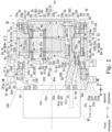
- Fig. 1 is a side view (partial sectional view) of a hydraulic motor, which is an example of a fluid device according to an embodiment of the invention.
- Fig. 2 is a sectional view along a line II-II in Fig. 1 .
- Fig. 3 is an enlarged view of a portion III of Fig. 1 .
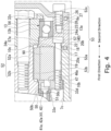
- Fig. 4 is an enlarged view of a portion IV of Fig. 1 .
- Fig. 5 is a sectional view along a line V-V in Fig. 1 .
- Fig. 6 is a sectional view along a line VI-VI in Fig. 1 .
- Fig. 1 is a side view (partial sectional view) of a hydraulic motor, which is an example of a fluid device according to an embodiment of the invention.
- Fig. 2 is a sectional view along a line II-II in Fig. 1 .
- Fig. 3 is an enlarged view of a portion III of Fig. 1
- FIG. 7 is a sectional view along the line VII-VII in Fig. 1 .
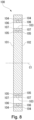
- Fig. 8 is a sectional view showing the distributor plate.
- Fig. 9 is a sectional view along a line IX-IX in Fig. 1 .
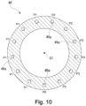
- Fig. 10 is a sectional view along a line X-X in Fig. 1 .
- Fig. 11 is a sectional view showing the flow channels in the hydraulic motor.
- the reference numeral 1 indicates the hydraulic motor.
- the following describes a fluid device relating to an embodiment of the present invention, taking a hydraulic motor as an example.
- the present embodiment is not limited to such, and the fluid device can be a hydraulic pump mechanism, for example.
- the hydraulic motor 1 includes a cylindrical oscillating housing part 2 and a rotatable part 3 that is rotatably supported on the inner peripheral surface of the oscillating housing part 2 via two bearings 12 and 13 (a first bearing 12 and a second bearing 13).
- the bearings 12 and 13 are angular ball bearings.
- the present embodiment is not limited to such, and the bearings 12 and 13 can be alternatively selected from a variety of bearings including other ball bearings such as deep groove ball bearings, or plain bearings, for example.
- the central axis of the oscillating housing part 2 coincides with the axis of rotation of the rotatable part 3.
- the central axis and the axis of rotation are collectively referred to as a first axis C1 (an example of an axis).
- the term "axial direction” may refer to a direction parallel to the first axis C1
- the term “circumferential direction” may refer to the direction of the rotation of the rotatable part 3
- the term “radial direction” may refer to the radial direction of the rotatable part 3.
- the oscillating housing part 2 is axially divided into a first oscillating housing 7 and a second oscillating housing 8.
- the first oscillating housing 7 faces a first direction (located on the left side in Fig. 1 ) in the axial direction.
- the second oscillating housing 8 faces a second direction opposite to the first direction (located on the right side in Fig. 1 ) in the axial direction.
- the oscillating housing part 2 is not necessarily axially divided, but may not be axially divided.
- the first oscillating housing 7 is shaped like a cylinder.
- An outer flange 9 projecting outward in the radial direction is formed on an outer peripheral surface 7a of the first oscillating housing 7 near a first end 7b that faces the first direction.
- the outer flange 9 is used to attach the hydraulic motor 1 to external equipment, which is not shown.
- a through hole 9a penetrates the outer flange 9 in the thickness direction (axial direction).
- a bolt (not shown) extends through the through hole 9a.
- a peripheral wall 7e of the first oscillating housing 7 has a thick portion 10 that is thicker than the other portion.
- the thick portion 10 extends from a second end 7d facing the second direction to the axial center of the first oscillating housing 7.
- a second end 10c of the thick portion 10, which faces the second direction, is on the same plane as the second end 7d of the first oscillating housing 7. Stated differently, the second end 10c of the thick portion 10 forms a part of the second end 7d of the first oscillating housing 7.
- An inner peripheral surface 10d of the thick portion 10 has a plurality of (for example, thirteen in this embodiment) pin grooves 10a.
- the pin grooves 10a extend in the axial direction along the entire thick portion 10, and are equally spaced away from each other in the circumferential direction.
- the pin grooves 10a have a semicircular shape when seen in the axial direction.
- Each pin groove 10a receives an internal tooth pin 90 (an example of an internal tooth) therein.
- the internal tooth pins 90 have a substantially cylindrical shape and are received in a rotatable manner.
- the internal tooth pins 90 radially inwardly protrude beyond the inner peripheral surface 10d of the thick portion 10 and the protruding portions of the internal tooth pins 90 are also shaped like a semicircle.
- the internal tooth pins 90 serve as internal teeth meshing with an oscillating gear 5, which will be described below.
- First through-holes 19 are formed in and extend through the outer peripheral portion of the thick portion 10 in the axial direction.
- the first through holes 19 are arranged between the pin grooves 10a and evenly spaced away from each other in the circumferential direction.
- the first through holes 19 receive shafts 20a of bolts 20 (introduced as an example of fastener parts and screws). Via the bolts 20, the first oscillating housing 7, the second oscillating housing 8, and a feeding and discharging plate 46, described below, are collectively tightened to form a single unit.
- a first bearing receiving part 11 is formed via a step part 11a so as to have a large inner diameter.
- the first bearing receiving part 11 is located on the first direction side with respect to the thick portion 10.
- An outer race 12a of the first bearing 12 is fitted into the first bearing receiving part 11.
- the first bearing 12 and the first oscillating housing 7 are accurately positioned relative to each other by allowing the outer race 12a to abut against the step part 11a.
- a seal receiving part 14 is formed via a step part 14a so as to have a large inner diameter.
- the seal receiving part 14 is located on the first direction side with respect to the first bearing receiving part 11.
- a sealing part 15 is partially fitted in the seal receiving part 14.
- the sealing part 15 provides sealing between the first oscillating housing 7 and the rotatable part 3.
- the sealing part 15 is a floating seal.
- the sealing part 15, however, is not limited to such, and various seals such as packing or mechanical seals can be alternatively used.
- a first-carrier first labyrinth part 16 is formed and has a greater inner diameter than the seal receiving part 14.
- the first-carrier first labyrinth part 16 forms a first labyrinth 38, when combined with the rotatable part 3.
- the first labyrinth 38 prevents dust and other particles from entering from the outside into the space between the first oscillating housing 7 and the rotatable part 3.
- the second end 7d of the first oscillating housing 7 defines a plane by which the first and second oscillating housings 7 and 8 are separated.
- the second end 7d of the first oscillating housing 7 has an entirely flat outer peripheral portion.
- An O-ring 18 is placed in the O-ring groove 17. The O-ring 18 provides for reliable sealing between the first and second oscillating housings 7 and 8.
- the second oscillating housing 8 is shaped like an annulus.
- a circumferential wall 8a of the second oscillating housing 8 has second through holes 22 formed therein.
- the second through holes 22 are positioned correspondingly to the first through holes 19 of the first oscillating housing 7 and in communication with the first through holes 19.
- the second through holes 22 have the same diameter as and coaxial with the first through holes 19.
- a large part of each second through hole 22 that faces the second direction forms a counterboring part 23.
- the counterboring part 23 receives a head 20b of a corresponding one of the bolts 20.
- a first end 8b of the second oscillating housing 8 that faces the first direction defines a plane by which the first and second oscillating housings 7 and 8 are separated.
- a press plate 21 is integrally formed on the first end 8b of the second oscillating housing 8 and extends radially inwardly from the inner peripheral surface 8c of the second oscillating housing 8.
- the press plate 21 has an annular shape when viewed in the axial direction.
- the press plate 21 closes, on the second direction side, working chambers 66a, 66b and 66c (see Fig. 11 ) formed between the inner peripheral surface 7c of the first oscillating housing 7 and the outer peripheral surface of the oscillating gear 5, which will be described below.
- the press plate 21 can be, for example, formed as being separated from the oscillating housing part 2.
- a second-carrier first labyrinth part 25 is formed in a large part of the inner peripheral surface 21a of the press plate 21, excluding its end facing the first direction.
- the second-carrier first labyrinth part 25 has, via a step part 25a, a greater inner diameter than the inner peripheral surface 21a of the press plate 21.
- the second-carrier first labyrinth part 25 forms a second labyrinth 40, when combined with the rotatable part 3.
- the second labyrinth 40 prevents the hydraulic oil from leaking out of the space between the second oscillating housing 8 and the rotatable part 3 (this will be described in detail below).
- a second bearing receiving part 24 is formed via a step part 24a so as to have a large inner diameter.
- the second bearing receiving part 24 is located on the second direction side with respect to the press plate 21.
- An outer race 13a of the second bearing 13 is fitted into the second bearing receiving part 24.
- the second bearing 13 and the second oscillating housing 8 are accurately positioned relative to each other by allowing the outer race 13a to abut against the step part 24a.
- An O-ring 27 is placed in the O-ring groove 26.
- the O-ring 27 provides for reliable sealing between the second oscillating housing 8 and a cover 29 described below.
- the second end 8d of the second oscillating housing 8 has a plurality of internally threaded parts 28.
- the internally threaded portions 28 are radially inside the O-ring groove 26 and evenly spaced away from each other in the circumferential direction.
- the internally threaded parts 28 are provided to secure the cover 29 onto the second oscillating housing 8.
- the cover 29 closes an opening 8e of the second oscillating housing 8 on the second-direction side.
- the cover 29 is made by, for example, subjecting a metal plate to stamping and has a central part a large part of which is swollen toward the second direction.
- the outer peripheral portion of the cover 29 forms an outer flange part 29a.
- the outer flange part 29a overlaps the second end 8d of the second oscillating housing 8.
- the outer flange part 29a has through holes 29b penetrating therethrough in the thickness direction of the cover 29.
- the through holes 29b are positioned correspondingly to the internally threaded portions 28 of the second oscillating housing 8.
- Bolts 30 are inserted into the through holes 29b from the second direction side. By tightening the bolts 30 into the internally threaded portions 28 of the second oscillating housing 8, the cover 29 is secured to the second oscillating housing 8.
- the feeding and discharging plate (port plate) 46 is securely held by the bolts 20 inserted into the first through holes 19 of the first oscillating housing 7 and the second through holes 22 of the second oscillating housing 8.
- the feeding and discharging plate 46 is located at a first end 10b of the thick portion 10, which is one of the ends of the thick portion 10.
- the feeding and discharging plate 46 is configured to feed hydraulic oil into and discharge hydraulic oil out of the working chambers 66a, 66b and 66c, which will be described below.
- the feeding and discharging plate 46 has an annular shape when viewed in the axial direction.
- the outer diameter of the feeding and discharging plate 46 is the same as or slightly less than the diameter of the inner peripheral surface 7c of the first oscillating housing 7. Therefore, the feeding and discharging plate 46 is fitted to the inner peripheral surface 7c of the first oscillating housing 7 and positioned at the first end 10b of the thick portion 10.
- the outer peripheral portion of the feeding and discharging plate 46 has internally threaded portions 47 that are positioned correspondingly to the first through holes 19 of the first oscillating housing 7.
- the bolts 20 are inserted, from the second oscillating housing 8 side, into the second through holes 22 and then into the first through holes 19 and finally tightened into the internally threaded portions 27 of the feeding and discharging plate 46. In this manner, via the bolts 20, the first oscillating housing 7, the second oscillating housing 8, and the feeding and discharging plate 46 are collectively tightened to form a single unit.
- a plurality of through holes 46a penetrating the feeding and discharging plate 46 in the thickness direction are formed.
- the through holes 46a can contribute to feed hydraulic oil into and discharge hydraulic oil out of the working chambers 66a, 66b and 66c, which will be described in detail below.
- the number of through holes 46a corresponds to the number of pin grooves 10a formed in the first oscillating housing 7. There are, for example, thirteen through holes 46a in the present embodiment.
- the through holes 46a feeding and discharging ports have openings facing the thick portion 10, which are arranged in the middle between adjacent ones of the pin grooves 10a arranged next to each other in the circumferential direction and positioned radially inside the inner peripheral surface 10d of the thick portion 10.
- a plate labyrinth part 48 is formed in a large part of the inner peripheral surface 46b of the feeding and discharging plate 46, excluding its end facing the second direction.
- the plate labyrinth part 48 has, via a step part 48a, a greater inner diameter than the inner peripheral surface 46b of the feeding and discharging plate 46.
- the plate labyrinth part 48 forms a third labyrinth 49, when combined with the rotatable part 3.
- the third labyrinth 49 prevents the hydraulic oil from leaking out of the space between the feeding and discharging plate 46 and the rotatable part 3 (this will be described in detail below).
- the rotatable part 3, which is rotatably held in the oscillating housing part 2, is mainly constituted by a carrier (rotatable member) 6, a plurality of (for example, in the present embodiment three) crankshafts 4, and an oscillating gear 5.
- the carrier 6 is rotatably supported via the bearings 12 and 13 on the respective sides in the axial direction, the crankshafts 4 are rotatably supported in the carrier 6, and the oscillating gear 5 is rotatably supported by the crankshafts 4.
- the carrier 6 is axially divided into a first carrier 31 and a second carrier 32.
- the first carrier 31 faces the first direction.
- the second carrier 32 faces the second direction.
- the first carrier 31 includes a disk-shaped substrate 33 and a plurality of (e.g., three in the present embodiment) pillars 34 protruding toward the second direction from a second end 33b of the substrate 33 that faces the second direction.
- the substrate 33 and pillars 34 are integrally molded.
- the outer peripheral surface 33c of the substrate 33 has a gradually increasing outer diameter, which is achieved by step parts, from the second end 33b toward the first end 33a that faces the first direction.
- the outer peripheral surface 33c of the substrate 33 is divided into a first outer peripheral surface 33d, a second outer peripheral surface 33e, a third outer peripheral surface 33f and a fourth outer peripheral surface 33g, which are arranged next to each other in the stated order starting from the second end 33b side.
- the second outer peripheral surface 33e is continuous from the first outer peripheral surface 33d via a large step part 33h and has a larger outer diameter than the first outer peripheral surface 33d.
- the third outer peripheral surface 33f is continuous from the second outer peripheral surface 33e via a small step part 33i and has a larger outer diameter than the second outer peripheral surface 33e.
- the fourth outer peripheral surface 33g is continuous from the third outer peripheral surface 33f via a medium step part 33j and has a larger outer diameter than the third outer peripheral surface 33f.
- the portion of the first carrier 31 where the first outer peripheral surface 33d is formed is accommodated in the plate labyrinth part 48 of the feeding and discharging plate 46.
- the outer diameter of the first outer peripheral surface 33d is slightly smaller than the inner diameter of the plate labyrinth part 48.
- the second end 33b of the first carrier 31 is located on the second direction side with respect to the step part 48a of the feeding and discharging plate 46.
- the first outer peripheral surface 33d and second end 33b of the first carrier 31 forms the third labyrinth 49 in conjunction with the plate labyrinth part 48 of the feeding and discharging plate 46.
- An inner race 12b of the first bearing 12 is fitted into the third outer peripheral surface 33f.
- the first bearing 12 and the first carrier 31 are accurately positioned relative to each other by allowing the inner race 12b to abut against the medium step part 33j. In this way, the first carrier 31 can be accurately positioned relative to the first oscillating housing 7. Furthermore, the first carrier 31 is rotatably supported by the first oscillating housing 7 via the first bearing 12.
- the fourth outer peripheral surface 33g of the first carrier 31 faces the sealing housing part 14 of the first oscillating housing 7 in the radial direction. This results in the sealing part 15 being positioned between the fourth outer peripheral surface 33g of the first carrier 31 and the sealing housing part 14 of the first oscillating housing 7.
- a disk 35 which is circular when viewed in the axial direction, is integrally formed on the end of the fourth outer peripheral surface 33g that faces the first direction.
- a second end 35b of the disk 35 which faces the second direction, faces the first end 7b of the first oscillating housing 7 in the axial direction.
- the outer diameter of the disk 35 is the same as the diameter of the outer peripheral surface 7a of the first oscillating housing 7.
- a sealing housing depression 36 which is annular when viewed in the axial direction, is formed on the second end 35b of the disk 35.
- the sealing housing depression 36 is smoothly continuous from the fourth outer peripheral surface 33g.
- the sealing part 15 is partially housed within the sealing housing depression 36. In this way, sealing is established between the first carrier 31 (the rotatable part 3) and the first oscillating housing 7.
- a first-carrier second labyrinth part 37 is formed and has a smaller outer diameter via a step.
- the first-carrier second labyrinth part 37 forms the first labyrinth 38 in conjunction with the first-carrier first labyrinth part 16 formed in the first oscillating housing 7. Since the first labyrinth 38 is positioned radially outside the sealing part 15, dust and other particles can be reliably prevented from entering from the outside into the space between the first oscillating housing 7 and the first carrier 31 (the rotatable part 3).
- An outer flange 39 projecting outward in the radial direction is formed on the outer peripheral surface 35c of the disk 35.
- the outer flange 39 is used to attach the hydraulic motor 1 to external equipment, which is not shown.
- a through hole 39a penetrates the outer flange 39 in the thickness direction (axial direction).
- a bolt (not shown) extends through the through hole 39a.
- a plurality of (for example, three in this embodiment) shaft supporting depressions 44 are formed in the second end 33b of the substrate 33 and arranged at equal intervals in the circumferential direction.
- the shaft supporting depressions 44 are formed near the outer peripheral portion of the second end 33b (radially inside the first outer peripheral surface 33d).
- the shaft supporting depressions 44 rotatably support the crankshafts 4.
- first bearings 59a are fitted to rotatably support the crankshafts 4.
- the first bearings 59a are, for example, plain bearings.
- the first bearings 59a are not limited to such, and various bearings such as ball bearings can be alternatively used.
- a plurality of feeding channels 41, a plurality of discharging channels 42, and a drain passage (tank channel) 43 are formed and extend over the entire axial length of the substrate 33.
- the feeding channels 41 are oil channels (flow channels) through which hydraulic oil is fed from a hydraulic pump (not shown).
- the feeding channels 41 open through the large step part 33h at their ends facing the second direction. In other words, each feeding channel 41 has a feeding opening 41a in the large step part 33h.
- the discharging channels 42 are oil channels (flow channels) through which hydraulic oil is discharged from inside the hydraulic motor 1.
- the discharging channels 42 also open through the large step part 33h at the ends facing the second direction. In other words, each discharging channel 42 has a discharging opening 42a in the large step part 33h.
- the numbers of feeding and discharging channels 41 and 42 are respectively different from the number of through holes 46a formed in the feeding and discharging plate 46 fixedly attached to the first oscillating housing 7.
- the numbers of feeding and discharging channels 41 and 42 are twelve, which is less by one than the number of through holes 46a in the feeding and discharging plate 46.
- the feeding openings 41a of the feeding channels 41 and the discharging openings 42a of the discharging channels 42 are alternately arranged in the circumferential direction on the same pitch circle.
- Each of the feeding openings 41a and a corresponding one of the discharging openings 42a form a pair, and the pairs of the feeding and discharging openings 41a and 42a are arranged at regular intervals in the circumferential direction.
- the drain passage 43 is a flow channel for returning leaking hydraulic oil in the hydraulic motor 1 back to a tank (not shown).
- the ends of the feeding channels 41, discharging channels 42 and drain passage 43 (the ends facing the first direction) are in communication with an oil distributor 45 via a distributor plate 100.
- the distributor plate 100 is provided at the first end 33a of the substrate 33.
- the distributor plate 100 has flow channels 103 to 107 for distributing the hydraulic oil into a plurality of flow channels.
- the oil distributor 45 has a plurality of flow channels 111 to 114, which will be described below.
- the distributor plate 100 is in contact with the first end 35a of the disk 35, which faces the first direction.
- the hydraulic oil from the hydraulic pump is fed to the flow channels 103 to 107. Then, through the distributing flow channels 103 to 107, the hydraulic oil from the flow channels 111 to 114 can be fed to the feeding channels 41.
- the hydraulic oil discharged into the discharging channels 42 is returned to a tank via the distributing flow channels 103 to 107 and the flow channels 111 to 114, or returned again back to the feeding channels 41.
- the hydraulic oil discharged into the drain passage 43 may also be returned to the tank via distributing flow channels (not shown). Note that how the hydraulic oil works will be described below in detail.
- a gap is created between the large step part 33h of the first carrier 31 and the feeding and discharging plate 46.
- a sliding plate (piston plate) 50 is disposed.
- the sliding plate 50 has an annular shape when viewed in the axial direction.
- the inner peripheral surface of the sliding plate 50 is fitted to the first outer peripheral surface 33d of the first carrier 31.
- the sliding plate 50 is non-rotatable relative to the first carrier 31 and slidable in the direction along the axis C1.
- the thickness of the sliding plate 50 is less than the gap between the large step part 33h and the feeding and discharging plate 46.
- the sliding plate 50 has a plurality of through holes (through ports) 50c correspondingly to the feeding openings 41a of the feeding channels 41 and the discharging openings 42a of the discharging channels 42.
- the through holes 50c corresponding to the feeding openings 41a are coaxially located with the feeding openings 41a.
- the through holes 50c corresponding to the discharging openings 42a are coaxially located with the discharging openings 42a.
- Each of the feeding and discharging openings 41a and 42a is provided with a cylindrical piston 51.
- the pistons 51 are slidable in the feeding and discharging channels 41 and 42.
- the pistons 51 are energized toward the sliding plate 50 by springs 51s provided in the feeding and discharging channels 41 and 42. Thus, the pistons 51 are pressed against the sliding plate 50.
- the thickness of the sliding plate 50 is less than the gap between the large step part 33h and the feeding and discharging plate 46. Therefore, due to the action of the springs 51s, the pistons 51 protrude beyond the large step part 33h to abut against the sliding plate 50. The surface 50b of the sliding plate 50 that faces the second direction is therefore pressed against the feeding and discharging plate 46. In this manner, via the pistons 51, the feeding channels 41 are in communication with the through holes 50c in the sliding plate 50. Furthermore, via the pistons 51, the discharging channels 42 are in communication with the through holes 50c of the sliding plate 50. In addition, the through holes 50c in the sliding plate 50 are in communication with the through holes 46a of the feeding and discharging plate 46.
- the pillars 34 of the first carrier 31 are formed as axially extending columns and shaped like a triangle when viewed in the axial direction.
- the pillars 34 are positioned, in the circumferential direction, between the shaft supporting depressions 44 of the substrate 33. This means that the pillars 34 are arranged at equal intervals in the circumferential direction on the second end 33b of the substrate 33.
- the diameter of the pitch circle of the pillars 34 is substantially the same as the diameter of the pitch circle of the shaft supporting depressions 44.
- the pillars 34 have flat ends 34a.
- the ends 34a of the pillars 34 are positioned on the same plane as the second end 7d of the first oscillating housing 7.
- the ends 34a of the pillars 34 have an internally threaded portion 52 for a reamer bolt.
- the internally threaded portion 52 has a mating depression 52a and a main body 52b.
- the mating depression 52a extends in the axial direction from the end 34a of the pillar 34 to the axially middle portion of the pillar 34.
- the main body 52b extends toward the first direction from the bottom of the mating depression 52a.
- the second carrier 32 is shaped like a circular plate.
- the second carrier 32 is positioned such that its first end 32a facing the first direction abuts against the ends 34a of the pillars 34 forming the first carrier 31 and remains in the position.
- a gap is thus left between the substrate 33 of the first carrier 31 and the second carrier 32.
- This gap is sized equally to the height of the pillars 34.
- This gap is surrounded by the thick portion 10 of the first oscillating housing 7, so that an oscillating gear housing part is formed to house the oscillating gear 5.
- the first end 32a of the second carrier 32 is entirely flat.
- the second carrier 32 has mating holes 54 penetrating therethrough in the thickness direction, which are positioned correspondingly to the internally threaded portions 52.
- Reamer bolts 53 are inserted into the mating holes 54 through the second carrier 32 from the second direction side.
- the first and second carriers 31 and 32 are integrally assembled together.
- the reamer bolts 53 are each divided into a shaft 53a, an externally threaded portion 53b and a head 53c.
- the externally threaded portion 53b protrudes from the first-direction-side end of the shaft 53a and coaxial with the shaft 53a.
- the head 53c is formed at the second-direction-side end of the shaft 53a.
- the second end 32b of the second carrier 32 that faces the second direction has counterboring parts 55 that are in communication with the mating holes 54.
- the counterboring parts 55 receive the heads 53c of the reamer bolts 53. This reduces the protruding height of the heads 53c of the reamer bolts 53 beyond the second end 32b of the second carrier 32.
- the outer peripheral surface 32c of the second carrier 32 has a diameter reduced part 56 via a step part 56a.
- the diameter reduced part 56 has a smaller outer diameter.
- An inner race 13b of the second bearing 13 is fitted into the diameter reduced part 56. In this manner, the second carrier 32 is rotatably supported by the second oscillating housing 8 via the second bearing 13.
- the diameter reduced part 56 has a second-carrier second labyrinth part 57, which is located on the first direction side with respect to the position where the second bearing 13 is fitted.
- the second-carrier second labyrinth part 57 has, via a step part 57a, a smaller outer diameter than the diameter reduced part 56.
- the outer diameter of the second-carrier second labyrinth part 57 is slightly smaller than the inner diameter of the second-carrier first labyrinth part 25 of the second oscillating housing 8.
- the end of the second-carrier second labyrinth part 57 is located on the second direction side with respect to the step part 25a of the second-carrier first labyrinth part 25.
- the second-carrier first labyrinth part 25 of the second oscillating housing 8 forms the second labyrinth 40 in conjunction with the second-carrier second labyrinth part 57 of the second carrier 33.
- a plurality of (for example, three in this embodiment) shaft supporting holes 58 are arranged at equal intervals in the circumferential direction and positioned radially inside the second-carrier second labyrinth part 57.
- the shaft supporting holes 58 rotatably support the crankshafts 4 (eccentric rotating members).
- the shaft supporting holes 58 and the shaft supporting depressions 44 of the first carrier 31 are coaxially arranged.
- second bearings 59b are fitted in the shaft supporting holes 58.
- the second bearings 59b are, for example, plain bearings.
- the second bearings 59b are not limited to such, and various bearings such as ball bearings can be alternatively used.
- crankshafts 4 are rotatably supported in the shaft supporting depressions 44 and shaft supporting holes 58 via the bearings 59a and 59b. In this manner, the crankshafts 4 are slidable and rotatable relative to the shaft supporting depressions 44 and shaft supporting holes 58 via the bearings 59a and 59b.
- the crankshafts 4 each have bearing parts 4a and 4b (first bearing part 4a and second bearing part 4b) and a cylindrical eccentric part 4c.
- the bearing parts 4a and 4b are rotatably supported in the shaft supporting depressions 44 and shaft supporting holes 58 via the bearings 59a and 59b.
- the eccentric part 4c is provided between and integrally formed with the bearing parts 4a and 4b.
- the axis of rotation of the crankshafts 4 (second axis C2) is parallel to the first axis C1.
- the second axis C2 is also the axes of the bearing parts 4a and 4b.
- the axial movement of the crankshafts 4 is restricted by thrust bearings 61a and 61b (first thrust bearing 61a and second thrust bearing 61b), a first collar 70a and a second collar 70b.
- the thrust bearings 61a and 61b are outside the bearing parts 4a and 4b in the axial direction.
- the first collars 70a are provided in the shaft supporting depressions 44 of the first carrier 31.
- the second collars 70b are provided in the shaft supporting holes 58 of the second carrier 58.
- the second thrust bearings 61b in the shaft supporting holes 58 of the second carrier 32 are restricted from moving toward the second direction by retaining rings 62 installed in the shaft supporting holes 58.
- the axial length of the eccentric part 4c is sized such that the eccentric part 4c can be housed within the axial width of the oscillating gear housing part. Specifically, the axial length of the eccentric part 4c is slightly less than the axial length of the thick portion 10 of the first oscillating housing 7. Accordingly, the second-direction-side end of the eccentric part 4c is substantially on the same plane as the first end 8b of the second oscillating housing 8.
- the axis of the eccentric part 4c (third axis C3) is shifted from the second axis C2 of the crankshaft 4.
- the eccentric parts 4c rotatably support the oscillating gear 5 via third bearings 59c.
- the third bearings 59c are, for example, plain bearings.
- the third bearings 59c are not limited to such, and various bearings such as ball bearings can be alternatively used.
- the outer diameter of the oscillating gear 5 is smaller than the diameter of the inner peripheral surface 10d of the thick portion 10, so that the oscillating gear 5 can be accommodated within the oscillating gear housing part.
- the axial thickness of the oscillating gear 5 is equivalent to that of the eccentric parts 4c, for example. Accordingly, the second-direction-side end of the oscillating gear 5 is substantially on the same plane as the first end 8b of the second oscillating housing 8.
- the oscillating gear 5 has support holes 63 that are positioned correspondingly to the crankshafts 4 and through which the eccentric parts 4c of the crankshafts 4 extend.
- the support holes 63 are arranged at equal intervals in the circumferential direction.
- third bearings 59c are provided in the support holes 63.
- the oscillating gear 5 is restricted from moving in the axial direction relative to the crankshafts 4, by retaining rings 67 provided at the respective axial ends of the third bearings 59c. In this way, the crankshafts 4 can allow the oscillating gear 5 to rotate only in an oscillatorily manner.
- the oscillating gear 5 has relief holes 64 that are positioned correspondingly to the pillars 34 of the first carrier 31 and through which the pillars 34 extend.
- the relief holes 64 are shaped like a triangle as viewed in the axial direction, so that the shape of the relief holes 64 corresponds to the shape of the pillars 34.
- the relief holes 64 are sufficiently larger than the size defined by the outer surface of the pillars 34, so that the pillars 34 do not intervene the oscillatory rotation of the oscillating gear 5.
- the outer peripheral surface of the oscillating gear 5 faces the internal tooth pins 90 of the first oscillating housing 7 in the radial direction.
- the outer peripheral surface of the oscillating gear 5 has external teeth 65 to mesh with the internal tooth pins 90.
- the number of external teeth 65 is different from the number of internal tooth pins 90.
- the number of external teeth 65 is 12 or smaller by one than the number of internal tooth pins 90. This number is the same as the numbers of feeding and discharging channels 41 and 42 formed in the first carrier 31.
- the oscillating gear 5 While oscillatorily rotating, the oscillating gear 5 constantly remains in contact with the internal tooth pins 90 at a portion between a tooth tip 65a and a tooth root 65b.
- the two working chambers 66a and 66b are line symmetrical to each other when seen in the axial direction. Between the working chambers 66a and 66b, a working chamber 66c is formed.
- the working chambers 66a and 66b are distinguished from each other according to the pressure during operation.
- the working chamber 66a refers to a space of high pressure that is in communication with the feeding channels 41
- the working chamber 66b refers to a space of low pressure that is in communication with the discharging channels 42.
- the working chamber 66c refers to a space of such a pressure that is connected to neither of the feeding channels 41 nor the discharging channels 42.
- the working chambers 66a and 66b are in communication with the through holes 46a in the feeding and discharging plate 46. Through the through holes 46a, the hydraulic oil can be fed to or discharged from the working chambers 66a and 66b. In this manner, the hydraulic motor 1 is rotated.
- the distributor plate 100 is sandwiched between the oil distributor 45 and the disk 35 in the thickness direction.
- the distributor plate 100 is positioned such that its end surfaces 101 and 102 are respectively in contact with the oil distributor 45 and the disk 35.
- the distributor plate 100 has third flow channels 103 to 107 connecting the first flow channels 111 to 114 and the feeding and discharging channels (second flow channels) 41 and 42.
- the distributor plate 100 is sandwiched between the oil distributor 45, which is a first housing, and the rotatable part 3 including the disk 35, which is a second housing, so that the third flow channels 103 to 107 allow the hydraulic oil (fluid) to branch and merge between the first flow channels 111 to 114 and the second flow channels 41 and 42.
- the end surface 101 of the distributor plate 100 that faces the first direction is in contact with the end surface 45a of the oil distributor 45.
- the end surface 102 of the distributor plate 100 that faces the second direction is in contact with the first end 35a of the disk 35.
- the distributor plate 100 can thus preserve tight sealing as the end surfaces 101 and 102 are pressed by the end surface 45a and the first end 35a.
- the oil distributor 45 and the disk 35 may be fastened together to press the distributor plate 100 on both sides.
- the distributor plate 100 has a plurality of through flow channels 103, which serve as the third flow channels.
- the through flow channels 103 extend through the distributor plate 100 in the thickness direction and are open at the end surfaces 101 and 102.
- the through flow channels 103 are arranged, on the end surfaces 101 and 102, along the same circle centered on the axis C1 and next to each other in the circumferential direction.
- the openings of the through flow channels 103 are separated from each other at equal intervals in the circumferential direction.
- the number of through flow channels 103 is equal to the total number of the feeding and discharging channels 41 and 42.
- the through flow channels 103 are positioned in correspondence with the pistons 51. In the present embodiment, 24 through flow channels 103 are arranged next to each other in the circumferential direction.
- the openings of the through flow channels 103 at the end surface 101 face the openings of the first flow channels 111 to 114 on the end surface 45a of the oil distributor 45. This allows the through flow channels 103 to be connected to the first flow channels 111 to 114. At the end surface 101, all of the through flow channels 103 do not necessarily need to face the first flow channels 111 to 114.
- the openings of the through flow channels 103 at the end surface 102 face the openings of the feeding and discharging channels 41 and 42 on the first end 35a of the disk 35. This allows the through flow channels 103 to be connected to the feeding and discharging channels 41 and 42. At the end surface 102, each of the through flow channels 103 faces a corresponding one of the feeding and discharging channels 41 and 42.
- the end surface 101 of the distributor plate 100 has, in the form of grooves, an outer circumferential connecting groove flow channel 104, an inner circumferential connecting groove flow channel 105, outward radial groove flow channels 106 and inward radial groove flow channels 107, which all serve as the third flow channels.
- the outer circumferential connecting groove flow channel 104, inner circumferential connecting groove flow channel 105, outward radial groove flow channels 106 and inward radial groove flow channels 107 serve as connecting groove flow channels for connecting together the through flow channels 103.
- the outer circumferential connecting groove flow channel 104 is shaped like an annulus along the circumferential direction of the distributor plate 100, and located radially outside the openings of the through flow channels 103 on the end surface 101.
- the outer circumferential connecting groove flow channel 104 has the same width and depth along the entire circumference.
- the inner circumferential connecting groove flow channel 105 is shaped like an annulus along the circumferential direction of the distributor plate 100, and located radially inside the openings of the through flow channels 103 on the end surface 101.
- the inner circumferential connecting groove flow channel 105 has the same width and depth along the entire circumference.
- the outer and inner circumferential connecting groove flow channels 104 and 105 have the same width and depth.
- the outer and inner circumferential connecting groove flow channels 104 and 105 are concentrically arranged around the axis C1.
- the outward radial groove flow channels 106 extend in the radial direction of the distributor plate 100, so that each outward radial groove flow channel 106 connects a predetermined through flow channel 103 of the through flow channels 103 next to each other in the circumferential direction, to the outer circumferential connecting groove flow channel 104.
- the inward radial groove flow channels 107 extend in the radial direction of the distributor plate 100, so that each inward radial groove flow channel 107 connects a predetermined through flow channel 103 of the through flow channels 103 next to each other in the circumferential direction, to the inner circumferential connecting groove flow channel 105.
- the end surface 102 of the distributor plate 100 also has, as the connecting groove flow channels for connecting together the through flow channels 103, an outer circumferential connecting groove flow channel 104, an inner circumferential connecting groove flow channel 105, outward radial groove flow channels 106 and inward radial groove flow channels 107.
- the outer and inner circumferential connecting groove flow channels 104 and 105 have substantially the same shape.
- the outer and inner circumferential connecting groove flow channels 104 and 105 in the end surfaces 101 and 102 are symmetrically arranged in the thickness direction.
- the outward and inward radial groove flow channels 106 and 107 have substantially the same shape. Note that the outward and inward radial groove flow channels 106 and 107 are differently positioned in the circumferential direction between the end surfaces 101 and 102.
- six through flow channels 103 are connected to the outer circumferential connecting groove flow channel 104 via the outward radial groove flow channels 106.
- six through flow channels 103 are connected to the inner circumferential connecting groove flow channel 105 via the inward radial groove flow channels 107.
- six through flow channels 103 are connected to the outer circumferential connecting groove flow channel 104 via the outward radial groove flow channels 106.
- six through flow channels 103 are connected to the inner circumferential connecting groove flow channel 105 via the inward radial groove flow channels 107.
- the outer circumferential connecting groove flow channel 104 formed on the end surface 101, the inner circumferential connecting groove flow channel 105 formed on the end surface 101, the outer circumferential connecting groove flow channel 104 formed on the end surface 102, and the inner circumferential connecting groove flow channel 105 formed on the end surface 102 form four separate and individual flow channels, in conjunction with the through flow channels 103 connected to these flow channels.
- These four flow channels provided in the distributor plate 100 correspond to the four first flow channels 111 to 114 formed in the oil distributor 45.
- Figs. 5 to 7 show how the four independent flow channels in the distributor plate 100 correspond to the four first flow channels 111 to 114.
- Each through flow channel 103 is connected to one of the four independent flow channels, specifically, one groove flow channel selected from among (i) one of the inward radial groove flow channels 107 formed on the end surface 101, (ii) one of the outward radial groove flow channels 106 formed on the end surface 101, (iii) one of the inward radial groove flow channels 107 formed on the end surface 102, and (iv) one of the outward radial groove flow channels 106 formed on the end surface 102.
- Each and single through flow channel 103 is not connected to two or more of the four independent flow channels, specifically, two or more groove flow channels from among (i) one of the inward radial groove flow channels 107 formed on the end surface 101, (ii) one of the outward radial groove flow channels 106 formed on the end surface 101, (iii) one of the inward radial groove flow channels 107 formed on the end surface 102, and (iv) one of the outward radial groove flow channels 106 formed on the end surface 102.
- adjacent four through flow channels 103 of the through flow channels 103 that are arranged next to each other in the circumferential direction respectively correspond to the outward and inward radial groove flow channels 106 and 107 formed on the end surfaces 101 and 102, and these adjacent four through flow channels 103 form one group.
- the corresponding orderly arrangement of the outward and inward radial groove flow channels 106 and 107 on the end surfaces 101 and 102 is repeated in the circumferential direction.
- one inward radial groove flow channel 107 formed on the end surface 101, one outward radial groove flow channel 106 formed on the end surface 101, one inward radial groove flow channel 107 formed on the end surface 102, and one outward radial groove flow channel 106 formed on the end surface 102 form one group, and the groups of groove flow channels 107 and 106 are arranged next to each other in the circumferential direction.
- one inward radial groove flow channel 107 formed on the end surface 101, one inward radial groove flow channel 107 formed on the end surface 102, one outward radial groove flow channel 106 formed on the end surface 101, and one outer radial groove flow channel 106 formed on the end surface 102 may form one group, and the groups of groove flow channels 107 and 106 may be arranged next to each other in the circumferential direction.
- the groups of inward and outward radial groove flow channels 107 and 106 may be arranged next to each other in the circumferential direction in the opposite direction, in other words, in the clockwise (or counterclockwise) direction when seen in plan view. In this way, a different pattern can be provided.
- the flow channel 111 is connected to the inward radial groove flow channels 107 that are formed on the end surface 102.
- the flow channel 112 is connected to the outward radial groove flow channels 106 that are formed on the end surface 102.
- the flow channel 113 is connected to the inward radial groove flow channels 107 that are formed on the end surface 101.
- the flow channel 114 is connected to the outward radial groove flow channels 106 that are formed on the end surface 101.
- the openings of the through flow channels 103 at the end surface 102 are connected to the feeding and discharging channels 41 and 42 formed in the substrate 33 and disk 35, which serve as the second housing 35.
- the feeding and discharging channels 41 and 42 formed in the substrate 33 and disk 35, which serve as the second housing 35.
- two of the independent flow channels are connected to the feeding channels 41, and the remaining two of the independent flow channels are connected to the discharging channels 42. Note that how the hydraulic oil works will be described below in detail. The following now describes in detail how the hydraulic motor 1 works.
- Hydraulic oil is fed from a hydraulic pump, which is not shown, to the hydraulic motor 1.
- the hydraulic oil is fed to the feeding channels 41 via the flow channels 111 and 113 of the oil distributor 45 and via the distributor plate 100.
- the hydraulic oil fed from the hydraulic pump is delivered through the flow channel 111 and flows into the distributor plate 100 through the openings at the end surface 45a of the oil distributor 45.
- the hydraulic oil flows, via one or more of the through flow channels 103, through the inward radial groove flow channels 107 formed on the end surface 101 and then into the inner circumferential connecting groove flow channel 105 formed on the end surface 101.
- the hydraulic oil flows through the inward radial groove flow channels 107 connected to the inner circumferential connecting groove flow channel 105, to be delivered into different one or more of the through flow channels 103.
- the hydraulic oil can be distributed into five through flow channels 103. After being distributed, the hydraulic oil then flows through these through flow channels 103 in the thickness direction of the distributor plate 100, so that the hydraulic oil can be fed to the feeding channels 41 via the openings of the through flow channels 103 on the end surface 102.
- the hydraulic oil fed from the hydraulic pump is delivered through the flow channel 113 and flows into the distributor plate 100 through the opening at the end surface 45a of the oil distributor 45. After flowing into the distributor plate 100, the hydraulic oil flows into the through flow channels 103 through the end surface 101 and flow through the through flow channels 103 in the thickness direction of the distributor plate 100. The hydraulic oil further flows through the inward radial groove flow channels 107 formed on the end surface 102 and finally into the inner circumferential connecting groove flow channel 105 formed on the end surface 102.
- the hydraulic oil flows through the inward radial groove flow channels 107 connected to the inner circumferential connecting groove flow channel 105, to branch into different one or more of the through flow channels 103.
- the hydraulic oil can be distributed into five through flow channels 103. After being distributed, the hydraulic oil is then fed to the feeding channels 41 via the openings of these through flow channels 103 on the end surface 102.
- the hydraulic oil is fed under the same pressure P1.
- the hydraulic oil (fluid) is fed at high pressure, which is indicated by the reference sign "P1.”
- the hydraulic oil is then fed to the working chambers 66a and 66b via the pistons 51 in the feeding openings 41a, the through holes 50c of the sliding plate 50, and the through holes 46a of the feeding and discharging plate 46.
- the sliding plate 50 which is configured to rotate integrally with the first carrier 31, is slidable together with the feeding and discharging plate 46, which is integrated with the oscillating housing part 2.
- the through holes 46a can be aligned with the through holes 50c.
- the hydraulic oil fed to the through holes 50c flows into the through holes 46a.
- the sliding plate 50 closes the through holes 46a and prevents the hydraulic oil from leaking or flowing back through the through holes 46a from the working chambers 66a and 66b.
- the number of feeding channels 41 (the number of feeding openings 41a and the number of through holes 50c in the sliding plate 50 in communication with the feeding openings 41a) is less by one than the number of through holes 46a of the feeding and discharging plate 46.
- the number of discharging channels 42 (the number of discharging openings 42a and the number of through holes 50c of the sliding plate 50 in communication with the discharging openings 42a) is less by one than the number of through holes 46a of the feeding and discharging plate 46. It is thus only the feeding channels 41 that are in communication through the through holes 46a of the feeding and discharging plate 46 with either one of the two working chambers 66a and 66b.
- the discharging channels 42 that are in communication through the through holes 46a of the feeding and discharging plate 46 with the other of the two working chambers 66a and 66b.
- the through holes 46a of the feeding and discharging plate 46 are not in communication with the through holes 50c of the sliding plate 50. Therefore, the feeding and discharging channels 41 and 42 are not in communication with the working chamber 66c.
- the pressure inside one of the two working chambers 66a and 66b is higher than the pressure inside the other of the two working chambers 66a and 66b.
- the following describes a case where the pressure P1 in the working chamber 66a (the left part in Fig. 2 ) is higher than the pressure P2 in the working chamber 66b (the right part in Fig. 2 ).
- the working chamber 66a with the higher pressure P1 will be referred to as the high-pressure working chamber 66a.
- the working chamber 66b with the lower pressure P2 than the high-pressure working chamber 66a is referred to as the low-pressure working chamber 66b.
- the high-pressure working chamber 66a is in communication with the feeding channels 41.
- the low-pressure working chamber 66b is in communication with the discharging channels 42. Through all of the discharging channels 42, the hydraulic oil flows under the same pressure P2. In Figs. 5 to 7 and 11 , the hydraulic oil (fluid) is discharged under a low pressure, which is indicated by the reference sign "P2.”
- the oscillating gear 5 As the hydraulic oil is fed to the high-pressure working chamber 66a, the oscillating gear 5 is pressed toward the low-pressure working chamber 66b (as indicated by the arrow Y1 in Fig. 2 ). The hydraulic oil is discharged from the low-pressure working chamber 66b through the discharging channels 42. As a result, on the low-pressure working chamber 66b side, the internal tooth pins 90 mesh with the external teeth 65 of the oscillating gear 5. Here, since the number of external teeth 65 is less by one than the number of internal tooth pins 90, the oscillating gear 5 is slightly shifted in the rotating direction.
- the carrier 6 accompanies the oscillating gear 5 via the crankshafts 4 and is shifted in the rotating direction.
- the rotatable part 3 is slightly rotated relative to the oscillating housing part 2.
- the sliding plate 50 is then rotated relative to the feeding and discharging plate 46. This changes the state of the communication between the through holes 50c in the sliding plate 50 and the through holes 46a of the feeding and discharging plate 46.
- the oscillating gear 5 oscillatorily rotates, the high-pressure working chamber 66a and the low-pressure working chamber 66b are both slightly shifted in the rotating direction.
- the through holes 46a can be aligned with the through holes 50c.
- the hydraulic oil is discharged from the low-pressure working chamber 66b into the through holes 50c.
- the sliding plate 50 closes the through holes 46a and prevents the hydraulic oil from being discharged through the through holes 46a from the working chambers 66a and 66b.
- the pistons 51 in the discharging openings 42a of the discharging channels 42 slide together with the sliding plate 50, which is configured to rotate integrally with the first carrier 31.
- the through holes 50c can be aligned with the pistons 51.
- the hydraulic oil discharged into the discharging channels 42 flows into the distributor plate 100 through the openings at the first end 35a of the disk 35.
- the hydraulic oil then flows into the through flow channels 103 through the openings on the end surface 102.
- the through flow channels 103 connected to the outer circumferential connecting groove flow channel 104 formed on the end surface 102 receive the hydraulic oil flowing from the corresponding discharging channels 42, and the hydraulic oil then flows, via the through flow channels 103, from the outward radial groove flow channels 106 on the end surface 102 into the outer circumferential connecting groove flow channel 104 on the end surface 102.
- the hydraulic oil which merges into the outer circumferential connecting groove flow channel 104 at the end surface 102, flows into the through flow channels 103 connected to the flow channel 112 at the end surface 101.
- the hydraulic oil flows, through the outer circumferential connecting groove flow channel 104 on the end surface 102, from five of the through flow channels 103 into the through flow channels 103 connected to the flow channel 112.
- the hydraulic oil then flows through the through flow channels 103 in the thickness direction of the distributor plate 100, so that the hydraulic oil can be discharged from the through flow channels 103 opening at the end surface 101 into the flow channels 112 via the openings on the end surface 45a.
- the through flow channels 103 receive the hydraulic oil flowing from the corresponding discharging channels 42, and the hydraulic oil then flows through the through flow channels 103 in the thickness direction of the distributor plate 100. After reaching the end surface 101, the hydraulic oil flows, through the through flow channels 103, from the outward radial groove flow channels 106 on the end surface 101 into the outer circumferential connecting groove flow channel 104 on the end surface 101.
- the hydraulic oil can flow from five of the through flow channels 103 into the through flow channels 103 connected to the flow channel 114, through the outer circumferential connecting groove flow channel 104 on the end surface 101.
- the hydraulic oil which merges into the outer circumferential connecting groove flow channel 104 at the end surface 101, flows into the through flow channels 103 connected to the flow channel 114 at the end surface 101.
- the hydraulic oil can then be discharged from the through flow channels 103 opening at the end surface 101 into the flow channel 114 via its opening on the end surface 45a.
- the hydraulic oil is discharged under the same pressure P2.
- the hydraulic oil (fluid) is discharged at low pressure, which is indicated by the reference sign "P2.”
- the hydraulic oil which is discharged from the working chamber 66b through the discharging channels 42, merges in the distributor plate 100 and is then discharged into the flow channels 112 and 114.
- the hydraulic motor 1 makes use of the difference between the number of feeding channels 41 (the number of feeding openings 41a and the number of through holes 50c in the sliding plate 50 in communication with the feeding openings 41a) and the number of through holes 46a in the feeding and discharging plate 46, and the difference between the number of discharging channels 42 (the number of discharging openings 42a and the number of through holes 50c in the sliding plate 50 in communication with the discharging openings 42a) and the number of through holes 46a in the feeding and discharging plate 46, such that the state of the communication between the through holes 50c in the sliding plate 50 and the through holes 46a in the feeding and discharging plate 46 is sequentially changed in the circumferential direction.
- the hydraulic oil is selectively fed to and discharged from the working chambers 66a and 66b through the through holes 46a in the feeding and discharging plate 46, so that the rotatable part 3 rotates.
- the carrier 6, which constitutes the rotatable part 3, is divided into the first carrier 31 and the second carrier 32.
- the first and second carriers 31 and 32 are fixedly coupled together using the reamer bolts 53. Therefore, power is transmitted between the first carrier 31 and the second carrier 32 through the reamer bolts 53.
- the shafts 53a of the reamer bolts 53 extend across the first and second carriers 31 and 32.
- the hydraulic oil fed to the working chambers 66a and 66b leak into the microgaps between the carriers 31 and 32 and the crankshafts 4 via the microgaps between the crankshafts 4 and the oscillating gear 5.
- the leaked hydraulic oil is discharged through the shaft supporting depressions 44 formed in the first carrier 31 into the drain passage 43 (tank channel).
- the hydraulic oil discharged into the drain passage 43 (tank channel) returns to the tank (not shown).
- the third labyrinth 49 is formed by the first outer peripheral surface 33d and the second end 33b of the first carrier 31 and the plate labyrinth part 48 of the feeding and discharging plate 46.
- the second labyrinth 40 is formed by the second-carrier first labyrinth part 25 of the second oscillating housing 8 and the second-carrier second labyrinth part 57 of the second carrier 32.
- the hydraulic oil may leak from the working chambers 66a and 66b through the microgaps between the crankshafts 4 and the oscillating gear 5, but hardly leak through the space between the first oscillating housing 7 and the first carrier 31 and through the space between the second oscillating housing 8 and the second carrier 32.
- the output can be provided by the rotatable part 3.
- it is an external device fixedly attached to the outer flange part 39 of the rotatable part 3 (first carrier 31) that is to be rotated.
- the rotatable part 3 may be stationary, and the output can be provided by the oscillating housing part 2.
- it is an external device fixedly attached to the outer flange part 9 of the oscillating housing part 2 (first oscillating housing 7) that is to be rotated.
- the hydraulic motor 1 has the internal tooth pins 90 in the first oscillating housing 7.
- the rotatable part 3 includes the carrier 6, the crankshafts 4 rotatably supported by the carrier 6, and the oscillating gear 5.
- the oscillating gear 5 is configured to oscillatorily rotate in response to the rotation of the crankshafts 4 and to mesh with the internal tooth pins 90.
- the hydraulic motor 1 can be rotated by feeding the hydraulic oil into and discharging the hydraulic oil from the working chambers 66a and 66b formed between the inner peripheral surface 7c of the first oscillating housing 7 and the outer peripheral surface of the oscillating gear 5.
- the rotation of the hydraulic motor 1 can produce high rotational torque.
- the oscillating housing part 2 which is constituted by separate parts, can be suitably used.
- the hydraulic motor 1 has the feeding and discharging plate 46 for selectively feeding the hydraulic oil to or discharging the hydraulic oil from the working chambers 66a and 66b.
- the feeding and discharging plate 46 is located at the first end 10b of the thick portion 10, which is one of the ends of the oscillating gear 5 that faces the first direction).
- the feeding and discharging plate 46 is fixedly attached to the first oscillating housing 7 using the bolts 20.
- the bolts 20 used to secure the first and second oscillating housings 7 and 8 are also used to secure the feeding and discharging plate 46. This can successfully reduce the number parts constituting the hydraulic motor 1.
- the hydraulic oil is fed from a hydraulic pump to the oil distributor 45, delivered through the flow channels 111 and 113, distributed by the distributor plate 100 into the feeding channels 41, and then fed to the working chambers 66a and 66b.
- the hydraulic oil is discharged from the working chambers 66a and 66b through the discharging channels 42, merged in the distributor plate 100 and then discharged into the flow channels 112 and 114.
- the distributor plate 100 has the through flow channels 103 connecting together the end surfaces 101 and 102 and the connecting groove flow channels 104 to 107 formed as grooves on the end surfaces 101 and 102. These third flow channels 103 to 107 are tightly sealed since the end surface 45a of the oil distributor 45, which is the first housing, tightly abut the end surface 101 and the first end 35a of the disk 35, which is the second housing, tightly abut the end surface 102. This facilitates the flow of the hydraulic oil (fluid) in the distributor plate 100.
- the distributor plate 100 thus connects the first flow channels 111 to 114 and the second flow channels 41 and 42. With such configurations, the distributor plate 100 can allow the hydraulic oil (fluid) to branch and merge between the first flow channels 111 to 114 and the second flow channels 41 and 42, which are larger in number than the first flow channels 111 to 114.
- the size of the hydraulic motor 1 can be reduced in the direction extending along the first axis C1. This means that, with the size remaining the same, the hydraulic motor 1 can produce increased output torque. Alternatively, with the output torque remaining the same, the hydraulic motor 1 can be reduced in size in the direction extending along the first axis C1, thereby saving the required space.
- the distributor plate 100 has the connecting groove flow channels 104 to 107 on the front and rear end surfaces 101 and 102. In this way, at most, four independent flow channels can be formed to allow the hydraulic oil to branch and merge. This allows for a first-speed operation according to which the hydraulic oil is fed from one flow channel 111 to the feeding channels 41 and a second-speed operation according to which the hydraulic oil is fed from the two flow channels 111 and 113 to the feeding channels 41.
- the hydraulic motor 1 employs the first-speed operation
- the hydraulic oil is discharged from the discharging channels 42 to the single flow channel 111.
- the hydraulic motor 1 employs the second-speed operation
- the hydraulic oil is discharged from the discharging channels 42 into the two flow channels 113.
- the end surfaces 101 and 102 have the connecting groove flow channels 104 to 107 formed therein, and tightly sealed flow channels can be formed simply by sandwiching the connecting groove flow channels 104 to 107 between two parts. This can provide for significantly improved sealing, when compared with the conventional technique where the grooves are formed on the circumferential surface.
- the through flow channels 103 arranged next to each other in the circumferential direction are spaced away from each other at equal intervals on the end surfaces 101 and 102. In this way, the through flow channels 103 can be connected to the feeding and discharging channels 41 and 42, which are alternately arranged in the circumferential direction in orbital motors.
- the outer and inner circumferential connecting groove flow channels 104 and 105 each connect more than one of the through flow channels 103.
- independent flow channels can be formed with selected ones of the through flow channels 103 at predetermined positions simply by processing a flat disk such that the through flow channels 103 extend through the flat disk and annular grooves are formed on the flat end surfaces to serve as the outer and inner circumferential connecting groove flow channels 104 and 105. Therefore, branching and merging can be easily accomplished even if the independent flow channels are subject to different pressures.
- the distributor plate 100 having the above features can be easily manufactured simply by cutting flat disks or through casting.
- the distributor plate 100 can remain highly reliably sealed by being sandwiched between the first and second housings, the end surfaces 101 and 102 do not need to be subject to very accurate machining.
- each through flow channel 103 can be selectively connected to one of the outer and inner circumferential connecting groove flow channels 104 and 105, since it is determined in advance which one of the outward and inward radial groove flow channels 106 and 107 is connected to each through flow channel 103. In this way, independent flow channels can be formed for branching and merging of the hydraulic oil.
- the distributor plate 100 is compatible with the second housing in which the feeding and discharging channels 41 and 42 under different pressures are adjacent to each other, and can accomplish branching and merging between the flow channels 111 to 114 and the feeding and discharging channels 41 and 42.
- the outward and inward radial groove flow channels 106 and 107 are connected to every other ones of the through flow channels 103 that are arranged next to each other in the circumferential direction. Therefore, of the feeding and discharging channels 41 and 42 subject to different pressures, the distributor plate 100 can establish connection between the flow channels 111 and 113 and the feeding channels 41 subject to a higher pressure for branching and merging. Furthermore, the distributor plate 100 can establish connection between the flow channels 112 and 114 and the discharging channels 42 subject to a lower pressure for branching and merging.
- branching and merging flow channels can be freely designed between the flow channels.
- the four independent flow channels can be freely designed and connected to the second flow channels simply by determining where the outward and inward radial groove flow channels 106 and 107 are formed.
- the outward and inward radial groove flow channels 106 and 107 are connected to four adjacent ones of the through flow channels 103 that are arranged next to each other in the circumferential direction, and these four through flow channels 103 form one group.
- the corresponding orderly arrangement of the outward and inward radial groove flow channels 106 and 107 is repeated in the circumferential direction.
- the four independent flow channels can be freely designed and connected to the second flow channels.
- the outward and inward radial groove flow channels 106 and 107 are connected to two adjacent ones of the through flow channels 103 that are arranged next to each other in the circumferential direction, and these two through flow channels 103 form one group.
- the bolts 20 are used as fixture parts for fixedly attaching together the first and second oscillating housings 7 and 8.
- the reamer bolts 53 are used as fixture parts for fixedly attaching together the first and second carriers 31 and 32.
- the present embodiment is not limited to such, and any parts can be used in place of the bots 20 and reamer bolts 53 as long as they can secure the oscillating housings 7 and 8 and the carriers 31 and 32.
- rivets and the like may be used as the fixture parts.
- the bolts 20 are used to secure the feeding and discharging plate 46 onto the first oscillating housing 7.
- the present embodiment is not limited to such, and different fixture members than the bolts 20 can be used to secure the feeding and discharging plate 46 onto the first oscillating housing 7.
- the feeding and discharging plate 46 does not need to be co-tightened with the first and second oscillating housings 7 and 8. If such is the case, each of the oscillating housings 7 and 8 may have, on the outer peripheral surface thereof, an outer flange part for securing the oscillating housings, and the oscillating housings 7 and 8 may be formed intro a single piece by securing the outer flange parts using bolts.
- the rotatable part 3 has three crankshafts 4, and these crankshafts 4 are used to restrict the rotation of the oscillating gear 5 to oscillatory rotation.
- the present embodiment is not limited to such, and the rotatable part 3 can be configured in any manner as long as it has at least one crankshaft 4.
- the second axis C2 of the crankshaft 4 is aligned with the first axis C1 of the rotatable part 3.
- a center crankshaft is employed. The center crankshaft restricts the rotation of the oscillating gear 5.
- the hydraulic oil can be subject to the high pressure P1 and low pressure P2.
- the first flow channels 111 to 114 are respectively subject to different pressures.
- the flow channels 111 to 114 may be respectively subject to pressures P1, P2, P3 and P4, and can be associated with four of the through flow channels 103 that are arranged next to each other in the circumferential direction in the distributor plate 100.
- the pressures P1, P2, P3 and P4 may be different from each other.
- two of them are the same and the remaining two are different from each other, so that three different pressures can be set.
- three of the pressures P1, P2, P3 and P4 are the same, so that two different pressures can be set.
Landscapes
- Engineering & Computer Science (AREA)
- Mechanical Engineering (AREA)
- General Engineering & Computer Science (AREA)
- Chemical & Material Sciences (AREA)
- Combustion & Propulsion (AREA)
- Hydraulic Motors (AREA)
- Rotary Pumps (AREA)
- Valve Housings (AREA)
Abstract
Description
- The present invention relates to a fluid device.
- Known hydraulic pump motors are disclosed in, for example, Patent Literature 1. Patent Literature 1 discloses that oil channels for distributing hydraulic oil are provided on a spindle at different positions in the circumferential direction. Patent Literature 1 further discloses a restraining member 130 forming the oil channels for delivering the hydraulic oil. The restraining member 130 has grooves depressed from the outer peripheral surface of the restraining member 130 and through holes extending through the restraining member 130 in the axial direction and positioned inside the grooves in the radial direction. The grooves and through holes are selectively in communication with each other. The restraining member 130 is fitted with a cylindrical hole 186 using shrink-fitting, which radially externally surrounds the restraining member 130 around its entire circumference.
- Patent Literature 1:
Japanese Patent Application Publication No. 2002-202069 - According to the conventional technique disclosed in Patent Literature 1, however, the oil channels are formed between the outer peripheral surface of the restraining member 130 and the inner peripheral surface of the cylindrical hole 186. This in turn means that a plurality of grooves are formed on the outer peripheral surface of the restraining member 130 and arranged next to each other in the axial direction. With such a structure, a small axial size of the restraining member 130 may hinder the fluid device from operating by hydraulic oil fed thereto and discharged therefrom. Therefore, the fluid device faces difficulties in achieving a smaller thickness.
- The present invention provides a fluid device that, while being simply structured, can achieve a small size and save a space.
- (1) A fluid device according to one aspect of the present invention has: a first housing having one or more first flow channels; a second housing having second flow channels that are larger in number than the first flow channels; and a distributor plate having a third flow channel connecting a predetermined one of the first flow channels and predetermined ones of the second flow channels. The distributor plate is sandwiched between the first housing and the second housing in a thickness direction of the distributor plate such that end surfaces of the distributor plate are in contact respectively with the first and second housings. The third flow channel includes: a plurality of through flow channels arranged next to each other in a circumferential direction, where the through flow channels open at the end surfaces; and one or more connecting groove flow channels extending in the circumferential direction, where the connecting groove flow channels connect together more than one of the through flow channels.
According to the fluid device relating to one aspect of the present invention, the first and second flow channels are linked through the distributor plate having grooves on their end surfaces to serve as connecting groove flow channels, so that the fluid can be distributed to the second flow channels that are larger in number than the first flow channels. In the direction from the first housing toward the second housing, it is only the thickness of the distributor plate that is required to distribute the fluid between the first flow channels and the second flow channels. When compared with the conventional art, the size of the device can be reduced in the direction extending from the first housing to the second housing. - (2) The connecting groove flow channels may be formed on respective one of the end surfaces of the distributor plate.
- (3) The through flow channels may be spaced away from each other at equal intervals in the circumferential direction on the end surfaces.
- (4) The connecting groove flow channels may include: an outer circumferential connecting groove flow channel located radially outside the through flow channels, where the outer circumferential connecting groove flow channel connects the through flow channels; and an inner circumferential connecting groove flow channel located radially inside the through flow channels, where the inner circumferential connecting groove flow channel connects together the through flow channels.
- (5) The third flow channel may further include: outward radial groove flow channels formed on the end surfaces and extending in a radial direction, where the outward radial groove flow channels radially connects the through flow channels and the outer circumferential connecting groove flow channel; and inward radial groove flow channels formed on the end surfaces and extending in the radial direction, where the inward radial groove flow channels radially connects the through flow channels and the inner circumferential connecting groove flow channel. The outward and inward radial groove flow channels may be connected to adjacent ones or every other ones of the through flow channels that are arranged next to each other in the circumferential direction.
- (6) The outward and inward radial groove flow channels may be arranged such that adjacent two or four of the through flow channels arranged next to each other in the circumferential direction form one group and the groups of the through flow channels are arranged next to each other in the circumferential direction.
- (7) The inner circumferential connecting groove flow channel, the through flow channels and the outer circumferential connecting groove flow channel may be arranged on concentric circles respectively on the end surfaces.
- (8) The second housing may include: an oscillating housing part extending along an axis; internal teeth formed on an inner peripheral surface of the oscillating housing part; a carrier supported on the oscillating housing part such that the carrier is rotatable around the axis, where the carrier is held with two bearings spaced away from each other in a direction extending along the axis of the oscillating housing part; a crankshaft supported on the carrier such that the crankshaft is rotatable around another axis parallel to the axis; an oscillating gear meshing with the internal teeth, where rotation of the oscillating gear is restricted by the crankshaft to oscillatory rotation; and a feeding and discharging plate having a plurality of feeding and discharging channels for feeding a working fluid to a space between the inner peripheral surface of the oscillating housing part and the oscillating gear and for discharging a working fluid from a space between the inner peripheral surface of the oscillating housing part and the oscillating gear. The feeding and discharging plate may be located on the oscillating gear to face the first housing in a direction extending along the axis, and the feeding and discharging channels may be in communication with the second flow channels.
- (9) The inner and outer circumferential connecting groove flow channels may be configured to feed and discharge a working fluid under different pressures or under a same pressure.
- (10) A fluid device according to another aspect of the present invention has a first housing having one or more first flow channels; a second housing having second flow channels that are larger in number than the first flow channels; and a distributor plate having a third flow channel connecting a predetermined one of the first flow channels and predetermined ones of the second flow channels. The distributor plate is sandwiched between the first housing and the second housing in a thickness direction of the distributor plate such that end surfaces of the distributor plate are in contact respectively with the first and second housings. The second housing includes: an oscillating housing part extending along an axis; internal teeth formed on an inner peripheral surface of the oscillating housing part; a carrier supported on the oscillating housing part such that the carrier is rotatable around the axis, where the carrier is held with two bearings spaced away from each other in a direction extending along the axis of the oscillating housing part; a crankshaft supported on the carrier such that the crankshaft is rotatable around another axis parallel to the axis; an oscillating gear meshing with the internal teeth, where rotation of the oscillating gear is restricted by the crankshaft to oscillatory rotation; and a feeding and discharging plate having a plurality of feeding and discharging channels for feeding a working fluid to a space between the inner peripheral surface of the oscillating housing part and the oscillating gear and for discharging a working fluid from a space between the inner peripheral surface of the oscillating housing part and the oscillating gear. The feeding and discharging plate is located on the oscillating gear to face the first housing in a direction extending along the axis, and the feeding and discharging channels are in communication with the second flow channels. The third flow channel includes: a plurality of through flow channels arranged next to each other in a circumferential direction, where the through flow channels open at the end surfaces; an outer circumferential connecting groove flow channel extending along the circumferential direction and formed on each of the end surfaces as a connecting groove flow channel connecting together the through flow channels, where the outer circumferential connecting groove flow channel is located outside the through flow channels in a radial direction and the outer circumferential connecting groove flow channel connecting the through flow channels; an inner circumferential connecting groove flow channel extending along the circumferential direction and formed on each of the end surfaces as the connecting groove flow channel, where the inner circumferential connecting groove flow channel is located inside the through flow channels in the radial direction and the inner circumferential connecting groove flow channel connects the through flow channels; outward radial groove flow channels formed on the end surfaces and extending in the radial direction, where the outward radial groove flow channels radially connects the through flow channels and the outer circumferential connecting groove flow channel; and inward radial groove flow channels formed on the end surfaces and extending in the radial direction, where the inward radial groove flow channels radially connects the through flow channels and the inner circumferential connecting groove flow channel. The outward and inward radial groove flow channels are connected to adjacent ones or every other ones of the through flow channels that are arranged next to each other in the circumferential direction, adjacent four of the through flow channels that are arranged next to each other in the circumferential direction form one group, and the outward and inward radial groove flow channels are arranged such that the groups of the through flow channels are arranged next to each other in the circumferential direction.
- With the configurations described above, the first and second flow channels are linked through the distributor plate having grooves on their end surfaces to serve as connecting groove flow channels, so that the fluid can branch and/or merge between the first flow channels and the second flow channels that are larger in number than the first flow channels. In the direction from the first housing toward the second housing, it is only the thickness of the distributor plate that is required to cause the fluid to be distributed between the first flow channels and the second flow channels. When compared with the conventional art, the size of the device can be reduced in the direction from the first housing to the second housing.
- Unlike the disclosure in Patent Literature 1, there is no need of forming multiple grooves depressed from the outer peripheral surface of the restraining member and arranged next to each other in the axial direction. Therefore, the fluid device can achieve a small axial size while being capable of operating by hydraulic oil fed thereto and discharged therefrom. In other words, the fluid device can accomplish a smaller thickness.
- The above-described configurations can provide improved sealing since the present invention can avoid the risk of leakage of the hydraulic oil caused by an accidental gap between the cylindrical hole and the restraining member providing the flow channels (oil channels), which is likely to be disadvantages of the configuration disclosed in Patent Literature 1. In addition, since the flat distributor plate is secured by being sandwiched between the first housing and the second housing, the distributor plate can remain pressed by a fastener or other members. This can provide for reliable tight sealing, thereby certainly improving the sealing.
- In addition, the distributor plate can be manufactured simply by forming grooves on the end surfaces as the third flow channel. This means that cutting or casting can be used to make the distributor plate, thereby reducing the number of steps involved in and the time required for the manufacturing. Furthermore, since the necessary tight seal can be maintained simply by flattening the end surfaces of the distributor plate, there is no demand for excessively high machining accuracy. In this way, the necessary tight sealing can be accomplished while simplified manufacturing can be also achieved.
- The present invention can provide a fluid device that, while being simply configured, is capable of achieving a small size and saving a space, keeping tight sealing of the hydraulic oil, and preventing leakage of the hydraulic oil, thereby improving the operating efficiency.
-
-
Fig. 1 is a side view (partial sectional view) of a hydraulic motor according to an embodiment of the invention. -
Fig. 2 is a sectional view along a line II-II inFig. 1 . -
Fig. 3 is an enlarged view of a portion III ofFig. 1 . -
Fig. 4 is an enlarged view of a portion VI ofFig. 1 . -
Fig. 5 is a sectional view along a line V-V inFig. 1 , showing flow channels in the hydraulic motor relating to the embodiment of the present invention. -
Fig. 6 is a sectional view along a line VI-VI ofFig. 1 , showing flow channels in a distributor plate relating to the embodiment of the present invention. -
Fig. 7 is a sectional view along a line VII-VII ofFig. 1 , showing the flow channels in the distributor plate relating to the embodiment of the present invention. -
Fig. 8 is a sectional view showing the distributor plate relating to the embodiment of the present invention. -
Fig. 9 is a sectional view along a line IX-IX inFig. 1 , showing the flow channels in the hydraulic motor relating to the embodiment of the present invention. -
Fig. 10 is a sectional view along a line X-X inFig. 1 , showing the flow channels in the hydraulic motor relating to the embodiment of the present invention. -
Fig. 11 is a sectional view showing the flow channels in the hydraulic motor relating to the embodiment of the present invention. -
Fig. 12 is a sectional view corresponding to the sectional view inFig. 7 , showing how different pressures are applied in the embodiment of the present invention. - A first embodiment of a fluid device according to the invention will be hereinafter described with reference to the accompanying drawings.
Fig. 1 is a side view (partial sectional view) of a hydraulic motor, which is an example of a fluid device according to an embodiment of the invention.Fig. 2 is a sectional view along a line II-II inFig. 1 .Fig. 3 is an enlarged view of a portion III ofFig. 1 .Fig. 4 is an enlarged view of a portion IV ofFig. 1 .Fig. 5 is a sectional view along a line V-V inFig. 1 .Fig. 6 is a sectional view along a line VI-VI inFig. 1 .Fig. 7 is a sectional view along the line VII-VII inFig. 1 .Fig. 8 is a sectional view showing the distributor plate.Fig. 9 is a sectional view along a line IX-IX inFig. 1 .Fig. 10 is a sectional view along a line X-X inFig. 1 .Fig. 11 is a sectional view showing the flow channels in the hydraulic motor. In the drawings, the reference numeral 1 indicates the hydraulic motor. - The following describes a fluid device relating to an embodiment of the present invention, taking a hydraulic motor as an example. The present embodiment, however, is not limited to such, and the fluid device can be a hydraulic pump mechanism, for example.
- As shown in
Figs. 1 to 4 , the hydraulic motor 1 includes a cylindricaloscillating housing part 2 and arotatable part 3 that is rotatably supported on the inner peripheral surface of theoscillating housing part 2 via twobearings 12 and 13 (afirst bearing 12 and a second bearing 13). Thebearings bearings - The central axis of the
oscillating housing part 2 coincides with the axis of rotation of therotatable part 3. In the following description, the central axis and the axis of rotation are collectively referred to as a first axis C1 (an example of an axis). In the following description, the term "axial direction" may refer to a direction parallel to the first axis C1, the term "circumferential direction" may refer to the direction of the rotation of therotatable part 3, and the term "radial direction" may refer to the radial direction of therotatable part 3. - As shown in
Figs. 1 to 4 , theoscillating housing part 2 is axially divided into a first oscillating housing 7 and a secondoscillating housing 8. The first oscillating housing 7 faces a first direction (located on the left side inFig. 1 ) in the axial direction. The secondoscillating housing 8 faces a second direction opposite to the first direction (located on the right side inFig. 1 ) in the axial direction. Theoscillating housing part 2 is not necessarily axially divided, but may not be axially divided. The first oscillating housing 7 is shaped like a cylinder. Anouter flange 9 projecting outward in the radial direction is formed on an outerperipheral surface 7a of the first oscillating housing 7 near afirst end 7b that faces the first direction. Theouter flange 9 is used to attach the hydraulic motor 1 to external equipment, which is not shown. A throughhole 9a penetrates theouter flange 9 in the thickness direction (axial direction). A bolt (not shown) extends through the throughhole 9a. - A
peripheral wall 7e of the first oscillating housing 7 has athick portion 10 that is thicker than the other portion. Thethick portion 10 extends from asecond end 7d facing the second direction to the axial center of the first oscillating housing 7. Asecond end 10c of thethick portion 10, which faces the second direction, is on the same plane as thesecond end 7d of the first oscillating housing 7. Stated differently, thesecond end 10c of thethick portion 10 forms a part of thesecond end 7d of the first oscillating housing 7. - An inner
peripheral surface 10d of thethick portion 10 has a plurality of (for example, thirteen in this embodiment)pin grooves 10a. Thepin grooves 10a extend in the axial direction along the entirethick portion 10, and are equally spaced away from each other in the circumferential direction. Thepin grooves 10a have a semicircular shape when seen in the axial direction. Eachpin groove 10a receives an internal tooth pin 90 (an example of an internal tooth) therein. The internal tooth pins 90 have a substantially cylindrical shape and are received in a rotatable manner. Since thepin grooves 10a have a semicircular shape when viewed in the axial direction, the internal tooth pins 90 radially inwardly protrude beyond the innerperipheral surface 10d of thethick portion 10 and the protruding portions of the internal tooth pins 90 are also shaped like a semicircle. The internal tooth pins 90 serve as internal teeth meshing with anoscillating gear 5, which will be described below. - First through-
holes 19 are formed in and extend through the outer peripheral portion of thethick portion 10 in the axial direction. The first throughholes 19 are arranged between thepin grooves 10a and evenly spaced away from each other in the circumferential direction. There are, for example, eight first through holes 19. The first throughholes 19 receiveshafts 20a of bolts 20 (introduced as an example of fastener parts and screws). Via thebolts 20, the first oscillating housing 7, the secondoscillating housing 8, and a feeding and dischargingplate 46, described below, are collectively tightened to form a single unit. - On the inner
peripheral surface 7c of the first oscillating housing 7, a first bearing receiving part 11 is formed via astep part 11a so as to have a large inner diameter. The first bearing receiving part 11 is located on the first direction side with respect to thethick portion 10. Anouter race 12a of thefirst bearing 12 is fitted into the first bearing receiving part 11. Thefirst bearing 12 and the first oscillating housing 7 are accurately positioned relative to each other by allowing theouter race 12a to abut against thestep part 11a. - On the inner
peripheral surface 7c of the first oscillating housing 7, aseal receiving part 14 is formed via astep part 14a so as to have a large inner diameter. Theseal receiving part 14 is located on the first direction side with respect to the first bearing receiving part 11. A sealingpart 15 is partially fitted in theseal receiving part 14. The sealingpart 15 provides sealing between the first oscillating housing 7 and therotatable part 3. For example, the sealingpart 15 is a floating seal. The sealingpart 15, however, is not limited to such, and various seals such as packing or mechanical seals can be alternatively used. - On the
first end 7b of the first oscillating housing 7, a first-carrierfirst labyrinth part 16 is formed and has a greater inner diameter than theseal receiving part 14. The first-carrierfirst labyrinth part 16 forms afirst labyrinth 38, when combined with therotatable part 3. Thefirst labyrinth 38 prevents dust and other particles from entering from the outside into the space between the first oscillating housing 7 and therotatable part 3. - The
second end 7d of the first oscillating housing 7 defines a plane by which the first and secondoscillating housings 7 and 8 are separated. Thesecond end 7d of the first oscillating housing 7 has an entirely flat outer peripheral portion. An O-ring groove 17, which is annular when viewed in the axial direction, is formed on thesecond end 7d between the first throughholes 19 and the outer peripheral portion. An O-ring 18 is placed in the O-ring groove 17. The O-ring 18 provides for reliable sealing between the first and secondoscillating housings 7 and 8. - The second
oscillating housing 8 is shaped like an annulus. A circumferential wall 8a of the secondoscillating housing 8 has second throughholes 22 formed therein. The second throughholes 22 are positioned correspondingly to the first throughholes 19 of the first oscillating housing 7 and in communication with the first through holes 19. The second throughholes 22 have the same diameter as and coaxial with the first through holes 19. A large part of each second throughhole 22 that faces the second direction forms acounterboring part 23. The counterboringpart 23 receives ahead 20b of a corresponding one of thebolts 20. - A
first end 8b of the secondoscillating housing 8 that faces the first direction defines a plane by which the first and secondoscillating housings 7 and 8 are separated. Apress plate 21 is integrally formed on thefirst end 8b of the secondoscillating housing 8 and extends radially inwardly from the innerperipheral surface 8c of the secondoscillating housing 8. Thepress plate 21 has an annular shape when viewed in the axial direction. Thepress plate 21 closes, on the second direction side, workingchambers Fig. 11 ) formed between the innerperipheral surface 7c of the first oscillating housing 7 and the outer peripheral surface of theoscillating gear 5, which will be described below. When the first and secondoscillating housings 7 and 8 are formed as a single unit, thepress plate 21 can be, for example, formed as being separated from theoscillating housing part 2. - In a large part of the inner
peripheral surface 21a of thepress plate 21, excluding its end facing the first direction, a second-carrierfirst labyrinth part 25 is formed. The second-carrierfirst labyrinth part 25 has, via astep part 25a, a greater inner diameter than the innerperipheral surface 21a of thepress plate 21. The second-carrierfirst labyrinth part 25 forms asecond labyrinth 40, when combined with therotatable part 3. Thesecond labyrinth 40 prevents the hydraulic oil from leaking out of the space between the secondoscillating housing 8 and the rotatable part 3 (this will be described in detail below). - On the inner
peripheral surface 8c of the secondoscillating housing 8, a secondbearing receiving part 24 is formed via a step part 24a so as to have a large inner diameter. The secondbearing receiving part 24 is located on the second direction side with respect to thepress plate 21. Anouter race 13a of thesecond bearing 13 is fitted into the secondbearing receiving part 24. Thesecond bearing 13 and the secondoscillating housing 8 are accurately positioned relative to each other by allowing theouter race 13a to abut against the step part 24a. - An O-
ring groove 26, which is annular when viewed in the axial direction, is formed on thesecond end 8d of the secondoscillating housing 8 that faces the second direction. An O-ring 27 is placed in the O-ring groove 26. The O-ring 27 provides for reliable sealing between the secondoscillating housing 8 and acover 29 described below. Thesecond end 8d of the secondoscillating housing 8 has a plurality of internally threadedparts 28. The internally threadedportions 28 are radially inside the O-ring groove 26 and evenly spaced away from each other in the circumferential direction. The internally threadedparts 28 are provided to secure thecover 29 onto the secondoscillating housing 8. - The
cover 29 closes anopening 8e of the secondoscillating housing 8 on the second-direction side. Thecover 29 is made by, for example, subjecting a metal plate to stamping and has a central part a large part of which is swollen toward the second direction. The outer peripheral portion of thecover 29 forms anouter flange part 29a. Theouter flange part 29a overlaps thesecond end 8d of the secondoscillating housing 8. - The
outer flange part 29a has throughholes 29b penetrating therethrough in the thickness direction of thecover 29. The throughholes 29b are positioned correspondingly to the internally threadedportions 28 of the secondoscillating housing 8.Bolts 30 are inserted into the throughholes 29b from the second direction side. By tightening thebolts 30 into the internally threadedportions 28 of the secondoscillating housing 8, thecover 29 is secured to the secondoscillating housing 8. - The feeding and discharging plate (port plate) 46 is securely held by the
bolts 20 inserted into the first throughholes 19 of the first oscillating housing 7 and the second throughholes 22 of the secondoscillating housing 8. The feeding and dischargingplate 46 is located at afirst end 10b of thethick portion 10, which is one of the ends of thethick portion 10. The feeding and dischargingplate 46 is configured to feed hydraulic oil into and discharge hydraulic oil out of the workingchambers - The feeding and discharging
plate 46 has an annular shape when viewed in the axial direction. The outer diameter of the feeding and dischargingplate 46 is the same as or slightly less than the diameter of the innerperipheral surface 7c of the first oscillating housing 7. Therefore, the feeding and dischargingplate 46 is fitted to the innerperipheral surface 7c of the first oscillating housing 7 and positioned at thefirst end 10b of thethick portion 10. - The outer peripheral portion of the feeding and discharging
plate 46 has internally threadedportions 47 that are positioned correspondingly to the first throughholes 19 of the first oscillating housing 7. Thebolts 20 are inserted, from the secondoscillating housing 8 side, into the second throughholes 22 and then into the first throughholes 19 and finally tightened into the internally threadedportions 27 of the feeding and dischargingplate 46. In this manner, via thebolts 20, the first oscillating housing 7, the secondoscillating housing 8, and the feeding and dischargingplate 46 are collectively tightened to form a single unit. - In a portion of the feeding and discharging
plate 46 that is radially inside of the internally threadedportions 47, a plurality of throughholes 46a (feeding and discharging ports) penetrating the feeding and dischargingplate 46 in the thickness direction are formed. The throughholes 46a can contribute to feed hydraulic oil into and discharge hydraulic oil out of the workingchambers holes 46a (feeding and discharging ports) corresponds to the number ofpin grooves 10a formed in the first oscillating housing 7. There are, for example, thirteen throughholes 46a in the present embodiment. The throughholes 46a (feeding and discharging ports) have openings facing thethick portion 10, which are arranged in the middle between adjacent ones of thepin grooves 10a arranged next to each other in the circumferential direction and positioned radially inside the innerperipheral surface 10d of thethick portion 10. - In a large part of the inner
peripheral surface 46b of the feeding and dischargingplate 46, excluding its end facing the second direction, aplate labyrinth part 48 is formed. Theplate labyrinth part 48 has, via astep part 48a, a greater inner diameter than the innerperipheral surface 46b of the feeding and dischargingplate 46. Theplate labyrinth part 48 forms athird labyrinth 49, when combined with therotatable part 3. Thethird labyrinth 49 prevents the hydraulic oil from leaking out of the space between the feeding and dischargingplate 46 and the rotatable part 3 (this will be described in detail below). - The
rotatable part 3, which is rotatably held in theoscillating housing part 2, is mainly constituted by a carrier (rotatable member) 6, a plurality of (for example, in the present embodiment three)crankshafts 4, and anoscillating gear 5. Thecarrier 6 is rotatably supported via thebearings crankshafts 4 are rotatably supported in thecarrier 6, and theoscillating gear 5 is rotatably supported by thecrankshafts 4. Thecarrier 6 is axially divided into afirst carrier 31 and asecond carrier 32. Thefirst carrier 31 faces the first direction. Thesecond carrier 32 faces the second direction. - The
first carrier 31 includes a disk-shapedsubstrate 33 and a plurality of (e.g., three in the present embodiment)pillars 34 protruding toward the second direction from asecond end 33b of thesubstrate 33 that faces the second direction. In thefirst carrier 31, thesubstrate 33 andpillars 34 are integrally molded. The outerperipheral surface 33c of thesubstrate 33 has a gradually increasing outer diameter, which is achieved by step parts, from thesecond end 33b toward thefirst end 33a that faces the first direction. - More specifically, the outer
peripheral surface 33c of thesubstrate 33 is divided into a first outerperipheral surface 33d, a second outerperipheral surface 33e, a third outerperipheral surface 33f and a fourth outerperipheral surface 33g, which are arranged next to each other in the stated order starting from thesecond end 33b side. The second outerperipheral surface 33e is continuous from the first outerperipheral surface 33d via alarge step part 33h and has a larger outer diameter than the first outerperipheral surface 33d. The third outerperipheral surface 33f is continuous from the second outerperipheral surface 33e via a small step part 33i and has a larger outer diameter than the second outerperipheral surface 33e. The fourth outerperipheral surface 33g is continuous from the third outerperipheral surface 33f via amedium step part 33j and has a larger outer diameter than the third outerperipheral surface 33f. - The portion of the
first carrier 31 where the first outerperipheral surface 33d is formed is accommodated in theplate labyrinth part 48 of the feeding and dischargingplate 46. The outer diameter of the first outerperipheral surface 33d is slightly smaller than the inner diameter of theplate labyrinth part 48. Thesecond end 33b of thefirst carrier 31 is located on the second direction side with respect to thestep part 48a of the feeding and dischargingplate 46. The first outerperipheral surface 33d andsecond end 33b of thefirst carrier 31 forms thethird labyrinth 49 in conjunction with theplate labyrinth part 48 of the feeding and dischargingplate 46. - An
inner race 12b of thefirst bearing 12 is fitted into the third outerperipheral surface 33f. Thefirst bearing 12 and thefirst carrier 31 are accurately positioned relative to each other by allowing theinner race 12b to abut against themedium step part 33j. In this way, thefirst carrier 31 can be accurately positioned relative to the first oscillating housing 7. Furthermore, thefirst carrier 31 is rotatably supported by the first oscillating housing 7 via thefirst bearing 12. - The fourth outer
peripheral surface 33g of thefirst carrier 31 faces the sealinghousing part 14 of the first oscillating housing 7 in the radial direction. This results in the sealingpart 15 being positioned between the fourth outerperipheral surface 33g of thefirst carrier 31 and the sealinghousing part 14 of the first oscillating housing 7. - A
disk 35, which is circular when viewed in the axial direction, is integrally formed on the end of the fourth outerperipheral surface 33g that faces the first direction. Asecond end 35b of thedisk 35, which faces the second direction, faces thefirst end 7b of the first oscillating housing 7 in the axial direction. The outer diameter of thedisk 35 is the same as the diameter of the outerperipheral surface 7a of the first oscillating housing 7. A sealinghousing depression 36, which is annular when viewed in the axial direction, is formed on thesecond end 35b of thedisk 35. The sealinghousing depression 36 is smoothly continuous from the fourth outerperipheral surface 33g. The sealingpart 15 is partially housed within the sealinghousing depression 36. In this way, sealing is established between the first carrier 31 (the rotatable part 3) and the first oscillating housing 7. - On the outer peripheral edge of the
second end 35b of thedisk 35, a first-carriersecond labyrinth part 37 is formed and has a smaller outer diameter via a step. The first-carriersecond labyrinth part 37 forms thefirst labyrinth 38 in conjunction with the first-carrierfirst labyrinth part 16 formed in the first oscillating housing 7. Since thefirst labyrinth 38 is positioned radially outside the sealingpart 15, dust and other particles can be reliably prevented from entering from the outside into the space between the first oscillating housing 7 and the first carrier 31 (the rotatable part 3). - An
outer flange 39 projecting outward in the radial direction is formed on the outerperipheral surface 35c of thedisk 35. Theouter flange 39 is used to attach the hydraulic motor 1 to external equipment, which is not shown. A throughhole 39a penetrates theouter flange 39 in the thickness direction (axial direction). A bolt (not shown) extends through the throughhole 39a. - A plurality of (for example, three in this embodiment) shaft supporting depressions 44 are formed in the
second end 33b of thesubstrate 33 and arranged at equal intervals in the circumferential direction. The shaft supporting depressions 44 are formed near the outer peripheral portion of thesecond end 33b (radially inside the first outerperipheral surface 33d). The shaft supporting depressions 44 rotatably support thecrankshafts 4. In the shaft supporting depressions 44,first bearings 59a are fitted to rotatably support thecrankshafts 4. Thefirst bearings 59a are, for example, plain bearings. Thefirst bearings 59a, however, are not limited to such, and various bearings such as ball bearings can be alternatively used. - In the portion of the
substrate 33 that is located radially inside the second outerperipheral surface 33e, a plurality of feeding channels 41, a plurality of discharging channels 42, and a drain passage (tank channel) 43 are formed and extend over the entire axial length of thesubstrate 33. The feeding channels 41 are oil channels (flow channels) through which hydraulic oil is fed from a hydraulic pump (not shown). The feeding channels 41 open through thelarge step part 33h at their ends facing the second direction. In other words, each feeding channel 41 has afeeding opening 41a in thelarge step part 33h. The discharging channels 42 are oil channels (flow channels) through which hydraulic oil is discharged from inside the hydraulic motor 1. The discharging channels 42 also open through thelarge step part 33h at the ends facing the second direction. In other words, each discharging channel 42 has a dischargingopening 42a in thelarge step part 33h. - The numbers of feeding and discharging channels 41 and 42 are respectively different from the number of through
holes 46a formed in the feeding and dischargingplate 46 fixedly attached to the first oscillating housing 7. For example, in the present embodiment, the numbers of feeding and discharging channels 41 and 42 are twelve, which is less by one than the number of throughholes 46a in the feeding and dischargingplate 46. Thefeeding openings 41a of the feeding channels 41 and the dischargingopenings 42a of the discharging channels 42 are alternately arranged in the circumferential direction on the same pitch circle. Each of thefeeding openings 41a and a corresponding one of the dischargingopenings 42a form a pair, and the pairs of the feeding and dischargingopenings - The
drain passage 43 is a flow channel for returning leaking hydraulic oil in the hydraulic motor 1 back to a tank (not shown). The ends of the feeding channels 41, discharging channels 42 and drain passage 43 (the ends facing the first direction) are in communication with anoil distributor 45 via adistributor plate 100. Thedistributor plate 100 is provided at thefirst end 33a of thesubstrate 33. Thedistributor plate 100 hasflow channels 103 to 107 for distributing the hydraulic oil into a plurality of flow channels. Theoil distributor 45 has a plurality offlow channels 111 to 114, which will be described below. Thedistributor plate 100 is in contact with thefirst end 35a of thedisk 35, which faces the first direction. - Through the
flow channels 111 to 114, the hydraulic oil from the hydraulic pump is fed to theflow channels 103 to 107. Then, through the distributingflow channels 103 to 107, the hydraulic oil from theflow channels 111 to 114 can be fed to the feeding channels 41. The hydraulic oil discharged into the discharging channels 42 is returned to a tank via the distributingflow channels 103 to 107 and theflow channels 111 to 114, or returned again back to the feeding channels 41. The hydraulic oil discharged into thedrain passage 43 may also be returned to the tank via distributing flow channels (not shown). Note that how the hydraulic oil works will be described below in detail. - A gap is created between the
large step part 33h of thefirst carrier 31 and the feeding and dischargingplate 46. In this gap, a sliding plate (piston plate) 50 is disposed. The slidingplate 50 has an annular shape when viewed in the axial direction. The inner peripheral surface of the slidingplate 50 is fitted to the first outerperipheral surface 33d of thefirst carrier 31. The slidingplate 50 is non-rotatable relative to thefirst carrier 31 and slidable in the direction along the axis C1. The thickness of the slidingplate 50 is less than the gap between thelarge step part 33h and the feeding and dischargingplate 46. - The sliding
plate 50 has a plurality of through holes (through ports) 50c correspondingly to thefeeding openings 41a of the feeding channels 41 and the dischargingopenings 42a of the discharging channels 42. The throughholes 50c corresponding to thefeeding openings 41a are coaxially located with thefeeding openings 41a. The throughholes 50c corresponding to the dischargingopenings 42a are coaxially located with the dischargingopenings 42a. - Each of the feeding and discharging
openings cylindrical piston 51. Thepistons 51 are slidable in the feeding and discharging channels 41 and 42. Thepistons 51 are energized toward the slidingplate 50 bysprings 51s provided in the feeding and discharging channels 41 and 42. Thus, thepistons 51 are pressed against the slidingplate 50. - The thickness of the sliding
plate 50 is less than the gap between thelarge step part 33h and the feeding and dischargingplate 46. Therefore, due to the action of thesprings 51s, thepistons 51 protrude beyond thelarge step part 33h to abut against the slidingplate 50. Thesurface 50b of the slidingplate 50 that faces the second direction is therefore pressed against the feeding and dischargingplate 46. In this manner, via thepistons 51, the feeding channels 41 are in communication with the throughholes 50c in the slidingplate 50. Furthermore, via thepistons 51, the discharging channels 42 are in communication with the throughholes 50c of the slidingplate 50. In addition, the throughholes 50c in the slidingplate 50 are in communication with the throughholes 46a of the feeding and dischargingplate 46. - The
pillars 34 of thefirst carrier 31 are formed as axially extending columns and shaped like a triangle when viewed in the axial direction. Thepillars 34 are positioned, in the circumferential direction, between the shaft supporting depressions 44 of thesubstrate 33. This means that thepillars 34 are arranged at equal intervals in the circumferential direction on thesecond end 33b of thesubstrate 33. The diameter of the pitch circle of thepillars 34 is substantially the same as the diameter of the pitch circle of the shaft supporting depressions 44. - The
pillars 34 haveflat ends 34a. The ends 34a of thepillars 34 are positioned on the same plane as thesecond end 7d of the first oscillating housing 7. The ends 34a of thepillars 34 have an internally threadedportion 52 for a reamer bolt. - The internally threaded
portion 52 has amating depression 52a and amain body 52b. Themating depression 52a extends in the axial direction from theend 34a of thepillar 34 to the axially middle portion of thepillar 34. Themain body 52b extends toward the first direction from the bottom of themating depression 52a. By tightening a reamer bolt (an example of another fastener) 53 into the internally threadedportion 52, the first andsecond carriers - The
second carrier 32 is shaped like a circular plate. Thesecond carrier 32 is positioned such that itsfirst end 32a facing the first direction abuts against theends 34a of thepillars 34 forming thefirst carrier 31 and remains in the position. A gap is thus left between thesubstrate 33 of thefirst carrier 31 and thesecond carrier 32. This gap is sized equally to the height of thepillars 34. This gap is surrounded by thethick portion 10 of the first oscillating housing 7, so that an oscillating gear housing part is formed to house theoscillating gear 5. - The
first end 32a of thesecond carrier 32 is entirely flat. Thesecond carrier 32 has mating holes 54 penetrating therethrough in the thickness direction, which are positioned correspondingly to the internally threadedportions 52.Reamer bolts 53 are inserted into the mating holes 54 through thesecond carrier 32 from the second direction side. By tightening thereamer bolts 53 into themain bodies 52b of the internally threadedportions 52 via themating depressions 52a of thepillars 34, the first andsecond carriers - The
reamer bolts 53 are each divided into ashaft 53a, an externally threadedportion 53b and ahead 53c. The externally threadedportion 53b protrudes from the first-direction-side end of theshaft 53a and coaxial with theshaft 53a. Thehead 53c is formed at the second-direction-side end of theshaft 53a. When thereamer bolts 53 are tightened into the internally threadedportions 52 designed for the reamer bolts, theshafts 53a of thereamer bolts 53 are fitted in themating depressions 52a of thepillars 34 and the mating holes 54 of thesecond carrier 32. In this manner, theshafts 53a of thereamer bolts 53 extend across the first andsecond carriers - The
second end 32b of thesecond carrier 32 that faces the second direction has counterboringparts 55 that are in communication with the mating holes 54. The counterboringparts 55 receive theheads 53c of thereamer bolts 53. This reduces the protruding height of theheads 53c of thereamer bolts 53 beyond thesecond end 32b of thesecond carrier 32. - The outer
peripheral surface 32c of thesecond carrier 32 has a diameter reducedpart 56 via astep part 56a. The diameter reducedpart 56 has a smaller outer diameter. Aninner race 13b of thesecond bearing 13 is fitted into the diameter reducedpart 56. In this manner, thesecond carrier 32 is rotatably supported by the secondoscillating housing 8 via thesecond bearing 13. - The diameter reduced
part 56 has a second-carriersecond labyrinth part 57, which is located on the first direction side with respect to the position where thesecond bearing 13 is fitted. The second-carriersecond labyrinth part 57 has, via astep part 57a, a smaller outer diameter than the diameter reducedpart 56. The outer diameter of the second-carriersecond labyrinth part 57 is slightly smaller than the inner diameter of the second-carrierfirst labyrinth part 25 of the secondoscillating housing 8. - The end of the second-carrier
second labyrinth part 57 is located on the second direction side with respect to thestep part 25a of the second-carrierfirst labyrinth part 25. The second-carrierfirst labyrinth part 25 of the secondoscillating housing 8 forms thesecond labyrinth 40 in conjunction with the second-carriersecond labyrinth part 57 of thesecond carrier 33. - A plurality of (for example, three in this embodiment)
shaft supporting holes 58 are arranged at equal intervals in the circumferential direction and positioned radially inside the second-carriersecond labyrinth part 57. Theshaft supporting holes 58 rotatably support the crankshafts 4 (eccentric rotating members). Theshaft supporting holes 58 and the shaft supporting depressions 44 of thefirst carrier 31 are coaxially arranged. In theshaft supporting holes 58,second bearings 59b are fitted. Thesecond bearings 59b are, for example, plain bearings. Thesecond bearings 59b, however, are not limited to such, and various bearings such as ball bearings can be alternatively used. - The
crankshafts 4 are rotatably supported in the shaft supporting depressions 44 andshaft supporting holes 58 via thebearings crankshafts 4 are slidable and rotatable relative to the shaft supporting depressions 44 andshaft supporting holes 58 via thebearings crankshafts 4. Thecrankshafts 4 each have bearingparts part 4a andsecond bearing part 4b) and a cylindricaleccentric part 4c. The bearingparts shaft supporting holes 58 via thebearings eccentric part 4c is provided between and integrally formed with the bearingparts - The axis of rotation of the crankshafts 4 (second axis C2) is parallel to the first axis C1. The second axis C2 is also the axes of the
bearing parts crankshafts 4 is restricted bythrust bearings 61a and 61b (first thrust bearing 61a and second thrust bearing 61b), afirst collar 70a and asecond collar 70b. Thethrust bearings 61a and 61b are outside the bearingparts first collars 70a are provided in the shaft supporting depressions 44 of thefirst carrier 31. Thesecond collars 70b are provided in theshaft supporting holes 58 of thesecond carrier 58. Of thethrust bearings 61a and 61b, thesecond thrust bearings 61b in theshaft supporting holes 58 of thesecond carrier 32 are restricted from moving toward the second direction by retainingrings 62 installed in the shaft supporting holes 58. - The axial length of the
eccentric part 4c is sized such that theeccentric part 4c can be housed within the axial width of the oscillating gear housing part. Specifically, the axial length of theeccentric part 4c is slightly less than the axial length of thethick portion 10 of the first oscillating housing 7. Accordingly, the second-direction-side end of theeccentric part 4c is substantially on the same plane as thefirst end 8b of the secondoscillating housing 8. The axis of theeccentric part 4c (third axis C3) is shifted from the second axis C2 of thecrankshaft 4. Theeccentric parts 4c rotatably support theoscillating gear 5 viathird bearings 59c. Thethird bearings 59c are, for example, plain bearings. Thethird bearings 59c, however, are not limited to such, and various bearings such as ball bearings can be alternatively used. - The outer diameter of the
oscillating gear 5 is smaller than the diameter of the innerperipheral surface 10d of thethick portion 10, so that theoscillating gear 5 can be accommodated within the oscillating gear housing part. The axial thickness of theoscillating gear 5 is equivalent to that of theeccentric parts 4c, for example. Accordingly, the second-direction-side end of theoscillating gear 5 is substantially on the same plane as thefirst end 8b of the secondoscillating housing 8. Theoscillating gear 5 has support holes 63 that are positioned correspondingly to thecrankshafts 4 and through which theeccentric parts 4c of thecrankshafts 4 extend. - The support holes 63 are arranged at equal intervals in the circumferential direction. In the support holes 63,
third bearings 59c are provided. Theoscillating gear 5 is restricted from moving in the axial direction relative to thecrankshafts 4, by retainingrings 67 provided at the respective axial ends of thethird bearings 59c. In this way, thecrankshafts 4 can allow theoscillating gear 5 to rotate only in an oscillatorily manner. - The
oscillating gear 5 hasrelief holes 64 that are positioned correspondingly to thepillars 34 of thefirst carrier 31 and through which thepillars 34 extend. The relief holes 64 are shaped like a triangle as viewed in the axial direction, so that the shape of the relief holes 64 corresponds to the shape of thepillars 34. The relief holes 64 are sufficiently larger than the size defined by the outer surface of thepillars 34, so that thepillars 34 do not intervene the oscillatory rotation of theoscillating gear 5. - The outer peripheral surface of the
oscillating gear 5 faces the internal tooth pins 90 of the first oscillating housing 7 in the radial direction. The outer peripheral surface of theoscillating gear 5 hasexternal teeth 65 to mesh with the internal tooth pins 90. The number ofexternal teeth 65 is different from the number of internal tooth pins 90. For example, in the present embodiment, the number ofexternal teeth 65 is 12 or smaller by one than the number of internal tooth pins 90. This number is the same as the numbers of feeding and discharging channels 41 and 42 formed in thefirst carrier 31. - While oscillatorily rotating, the
oscillating gear 5 constantly remains in contact with the internal tooth pins 90 at a portion between atooth tip 65a and atooth root 65b. This roughly creates two workingchambers chamber 66a and second workingchamber 66b) between (i) the innerperipheral surface 10d of thethick portion 10 of the first oscillating housing 7 and (ii) theexternal teeth 65 of theoscillating gear 5. The two workingchambers chambers chamber 66c is formed. The workingchambers chamber 66a refers to a space of high pressure that is in communication with the feeding channels 41, and the workingchamber 66b refers to a space of low pressure that is in communication with the discharging channels 42. Accordingly, the workingchamber 66c refers to a space of such a pressure that is connected to neither of the feeding channels 41 nor the discharging channels 42. - The working
chambers holes 46a in the feeding and dischargingplate 46. Through the throughholes 46a, the hydraulic oil can be fed to or discharged from the workingchambers - As shown in
Figs. 1 and5 to 8 , thedistributor plate 100 is sandwiched between theoil distributor 45 and thedisk 35 in the thickness direction. Thedistributor plate 100 is positioned such that itsend surfaces oil distributor 45 and thedisk 35. Thedistributor plate 100 hasthird flow channels 103 to 107 connecting thefirst flow channels 111 to 114 and the feeding and discharging channels (second flow channels) 41 and 42. Thedistributor plate 100 is sandwiched between theoil distributor 45, which is a first housing, and therotatable part 3 including thedisk 35, which is a second housing, so that thethird flow channels 103 to 107 allow the hydraulic oil (fluid) to branch and merge between thefirst flow channels 111 to 114 and the second flow channels 41 and 42. - The
end surface 101 of thedistributor plate 100 that faces the first direction is in contact with theend surface 45a of theoil distributor 45. Theend surface 102 of thedistributor plate 100 that faces the second direction is in contact with thefirst end 35a of thedisk 35. Thedistributor plate 100 can thus preserve tight sealing as the end surfaces 101 and 102 are pressed by theend surface 45a and thefirst end 35a. Alternatively, theoil distributor 45 and thedisk 35 may be fastened together to press thedistributor plate 100 on both sides. - The
distributor plate 100 has a plurality of throughflow channels 103, which serve as the third flow channels. The throughflow channels 103 extend through thedistributor plate 100 in the thickness direction and are open at the end surfaces 101 and 102. The throughflow channels 103 are arranged, on the end surfaces 101 and 102, along the same circle centered on the axis C1 and next to each other in the circumferential direction. The openings of the throughflow channels 103 are separated from each other at equal intervals in the circumferential direction. The number of throughflow channels 103 is equal to the total number of the feeding and discharging channels 41 and 42. The throughflow channels 103 are positioned in correspondence with thepistons 51. In the present embodiment, 24 throughflow channels 103 are arranged next to each other in the circumferential direction. - The openings of the through
flow channels 103 at theend surface 101 face the openings of thefirst flow channels 111 to 114 on theend surface 45a of theoil distributor 45. This allows the throughflow channels 103 to be connected to thefirst flow channels 111 to 114. At theend surface 101, all of the throughflow channels 103 do not necessarily need to face thefirst flow channels 111 to 114. The openings of the throughflow channels 103 at theend surface 102 face the openings of the feeding and discharging channels 41 and 42 on thefirst end 35a of thedisk 35. This allows the throughflow channels 103 to be connected to the feeding and discharging channels 41 and 42. At theend surface 102, each of the throughflow channels 103 faces a corresponding one of the feeding and discharging channels 41 and 42. - In addition, the
end surface 101 of thedistributor plate 100 has, in the form of grooves, an outer circumferential connectinggroove flow channel 104, an inner circumferential connectinggroove flow channel 105, outward radialgroove flow channels 106 and inward radialgroove flow channels 107, which all serve as the third flow channels. The outer circumferential connectinggroove flow channel 104, inner circumferential connectinggroove flow channel 105, outward radialgroove flow channels 106 and inward radialgroove flow channels 107 serve as connecting groove flow channels for connecting together the throughflow channels 103. The outer circumferential connectinggroove flow channel 104 is shaped like an annulus along the circumferential direction of thedistributor plate 100, and located radially outside the openings of the throughflow channels 103 on theend surface 101. The outer circumferential connectinggroove flow channel 104 has the same width and depth along the entire circumference. - The inner circumferential connecting
groove flow channel 105 is shaped like an annulus along the circumferential direction of thedistributor plate 100, and located radially inside the openings of the throughflow channels 103 on theend surface 101. The inner circumferential connectinggroove flow channel 105 has the same width and depth along the entire circumference. The outer and inner circumferential connectinggroove flow channels groove flow channels - The outward radial
groove flow channels 106 extend in the radial direction of thedistributor plate 100, so that each outward radialgroove flow channel 106 connects a predetermined throughflow channel 103 of the throughflow channels 103 next to each other in the circumferential direction, to the outer circumferential connectinggroove flow channel 104. The inward radialgroove flow channels 107 extend in the radial direction of thedistributor plate 100, so that each inward radialgroove flow channel 107 connects a predetermined throughflow channel 103 of the throughflow channels 103 next to each other in the circumferential direction, to the inner circumferential connectinggroove flow channel 105. - Like the
end surface 101, theend surface 102 of thedistributor plate 100 also has, as the connecting groove flow channels for connecting together the throughflow channels 103, an outer circumferential connectinggroove flow channel 104, an inner circumferential connectinggroove flow channel 105, outward radialgroove flow channels 106 and inward radialgroove flow channels 107. In the end surfaces 101 and 102, the outer and inner circumferential connectinggroove flow channels groove flow channels groove flow channels groove flow channels - In the present embodiment, on the
end surface 101, six throughflow channels 103 are connected to the outer circumferential connectinggroove flow channel 104 via the outward radialgroove flow channels 106. In addition, six throughflow channels 103 are connected to the inner circumferential connectinggroove flow channel 105 via the inward radialgroove flow channels 107. On theend surface 102, six throughflow channels 103 are connected to the outer circumferential connectinggroove flow channel 104 via the outward radialgroove flow channels 106. In addition, six throughflow channels 103 are connected to the inner circumferential connectinggroove flow channel 105 via the inward radialgroove flow channels 107. - The outer circumferential connecting
groove flow channel 104 formed on theend surface 101, the inner circumferential connectinggroove flow channel 105 formed on theend surface 101, the outer circumferential connectinggroove flow channel 104 formed on theend surface 102, and the inner circumferential connectinggroove flow channel 105 formed on theend surface 102 form four separate and individual flow channels, in conjunction with the throughflow channels 103 connected to these flow channels. These four flow channels provided in thedistributor plate 100 correspond to the fourfirst flow channels 111 to 114 formed in theoil distributor 45.Figs. 5 to 7 show how the four independent flow channels in thedistributor plate 100 correspond to the fourfirst flow channels 111 to 114. - Each through
flow channel 103 is connected to one of the four independent flow channels, specifically, one groove flow channel selected from among (i) one of the inward radialgroove flow channels 107 formed on theend surface 101, (ii) one of the outward radialgroove flow channels 106 formed on theend surface 101, (iii) one of the inward radialgroove flow channels 107 formed on theend surface 102, and (iv) one of the outward radialgroove flow channels 106 formed on theend surface 102. Each and single throughflow channel 103 is not connected to two or more of the four independent flow channels, specifically, two or more groove flow channels from among (i) one of the inward radialgroove flow channels 107 formed on theend surface 101, (ii) one of the outward radialgroove flow channels 106 formed on theend surface 101, (iii) one of the inward radialgroove flow channels 107 formed on theend surface 102, and (iv) one of the outward radialgroove flow channels 106 formed on theend surface 102. - In this manner, adjacent four through
flow channels 103 of the throughflow channels 103 that are arranged next to each other in the circumferential direction respectively correspond to the outward and inward radialgroove flow channels flow channels 103 form one group. The corresponding orderly arrangement of the outward and inward radialgroove flow channels groove flow channel 107 formed on theend surface 101, one outward radialgroove flow channel 106 formed on theend surface 101, one inward radialgroove flow channel 107 formed on theend surface 102, and one outward radialgroove flow channel 106 formed on theend surface 102 form one group, and the groups ofgroove flow channels groove flow channel 107 formed on theend surface 101, one inward radialgroove flow channel 107 formed on theend surface 102, one outward radialgroove flow channel 106 formed on theend surface 101, and one outer radialgroove flow channel 106 formed on theend surface 102 may form one group, and the groups ofgroove flow channels groove flow channels - In the present embodiment, the following features are described as an example. The
flow channel 111 is connected to the inward radialgroove flow channels 107 that are formed on theend surface 102. Theflow channel 112 is connected to the outward radialgroove flow channels 106 that are formed on theend surface 102. Theflow channel 113 is connected to the inward radialgroove flow channels 107 that are formed on theend surface 101. Theflow channel 114 is connected to the outward radialgroove flow channels 106 that are formed on theend surface 101. In this way, when theflow channels 111 to 114 are subject to different pressures, the four independent flow channels can be controlled to be subject to the corresponding pressures. - The openings of the through
flow channels 103 at theend surface 102 are connected to the feeding and discharging channels 41 and 42 formed in thesubstrate 33 anddisk 35, which serve as thesecond housing 35. Of the four independent flow channels described above, two of the independent flow channels are connected to the feeding channels 41, and the remaining two of the independent flow channels are connected to the discharging channels 42. Note that how the hydraulic oil works will be described below in detail. The following now describes in detail how the hydraulic motor 1 works. - The following describes how the hydraulic motor 1 works. Hydraulic oil is fed from a hydraulic pump, which is not shown, to the hydraulic motor 1. The hydraulic oil is fed to the feeding channels 41 via the
flow channels oil distributor 45 and via thedistributor plate 100. - Accordingly, as shown in
Figs. 5 to 7 , the hydraulic oil fed from the hydraulic pump is delivered through theflow channel 111 and flows into thedistributor plate 100 through the openings at theend surface 45a of theoil distributor 45. After flowing into thedistributor plate 100, the hydraulic oil flows, via one or more of the throughflow channels 103, through the inward radialgroove flow channels 107 formed on theend surface 101 and then into the inner circumferential connectinggroove flow channel 105 formed on theend surface 101. - In the
distributor plate 100, the hydraulic oil flows through the inward radialgroove flow channels 107 connected to the inner circumferential connectinggroove flow channel 105, to be delivered into different one or more of the throughflow channels 103. In thedistributor plate 100 of the present embodiment, the hydraulic oil can be distributed into five throughflow channels 103. After being distributed, the hydraulic oil then flows through these throughflow channels 103 in the thickness direction of thedistributor plate 100, so that the hydraulic oil can be fed to the feeding channels 41 via the openings of the throughflow channels 103 on theend surface 102. - Likewise, as shown in
Figs. 5 to 7 , the hydraulic oil fed from the hydraulic pump is delivered through theflow channel 113 and flows into thedistributor plate 100 through the opening at theend surface 45a of theoil distributor 45. After flowing into thedistributor plate 100, the hydraulic oil flows into the throughflow channels 103 through theend surface 101 and flow through the throughflow channels 103 in the thickness direction of thedistributor plate 100. The hydraulic oil further flows through the inward radialgroove flow channels 107 formed on theend surface 102 and finally into the inner circumferential connectinggroove flow channel 105 formed on theend surface 102. - In the
distributor plate 100, the hydraulic oil flows through the inward radialgroove flow channels 107 connected to the inner circumferential connectinggroove flow channel 105, to branch into different one or more of the throughflow channels 103. In thedistributor plate 100 of the present embodiment, the hydraulic oil can be distributed into five throughflow channels 103. After being distributed, the hydraulic oil is then fed to the feeding channels 41 via the openings of these throughflow channels 103 on theend surface 102. - Through the feeding channels 41 and
flow channels Figs. 5 to 7 and11 , the hydraulic oil (fluid) is fed at high pressure, which is indicated by the reference sign "P1." After fed to the feeding channels 41, the hydraulic oil is then fed to the workingchambers pistons 51 in thefeeding openings 41a, the throughholes 50c of the slidingplate 50, and the throughholes 46a of the feeding and dischargingplate 46. - While being energized toward the sliding
plate 50 by thesprings 51s, thepistons 51 in thefeeding openings 41a slide together with the slidingplate 50, which rotates integrally with thefirst carrier 31. As a result of the rotation of the slidingplate 50, the throughholes 50c can be aligned with thepistons 51. When this happens, the hydraulic oil fed to the feeding channels 41 flows into the throughholes 50c. - The sliding
plate 50, which is configured to rotate integrally with thefirst carrier 31, is slidable together with the feeding and dischargingplate 46, which is integrated with theoscillating housing part 2. As a result of the rotation of the slidingplate 50 and feeding and dischargingplate 46, the throughholes 46a can be aligned with the throughholes 50c. When this happens, the hydraulic oil fed to the throughholes 50c flows into the throughholes 46a. When the throughholes 46a are not in communication with the throughholes 50c, the slidingplate 50 closes the throughholes 46a and prevents the hydraulic oil from leaking or flowing back through the throughholes 46a from the workingchambers - The number of feeding channels 41 (the number of
feeding openings 41a and the number of throughholes 50c in the slidingplate 50 in communication with thefeeding openings 41a) is less by one than the number of throughholes 46a of the feeding and dischargingplate 46. In addition, the number of discharging channels 42 (the number of dischargingopenings 42a and the number of throughholes 50c of the slidingplate 50 in communication with the dischargingopenings 42a) is less by one than the number of throughholes 46a of the feeding and dischargingplate 46. It is thus only the feeding channels 41 that are in communication through the throughholes 46a of the feeding and dischargingplate 46 with either one of the two workingchambers holes 46a of the feeding and dischargingplate 46 with the other of the two workingchambers chamber 66c, the throughholes 46a of the feeding and dischargingplate 46 are not in communication with the throughholes 50c of the slidingplate 50. Therefore, the feeding and discharging channels 41 and 42 are not in communication with the workingchamber 66c. - Accordingly, the pressure inside one of the two working
chambers chambers chamber 66a (the left part inFig. 2 ) is higher than the pressure P2 in the workingchamber 66b (the right part inFig. 2 ). Furthermore, in the following description, the workingchamber 66a with the higher pressure P1 will be referred to as the high-pressure working chamber 66a. The workingchamber 66b with the lower pressure P2 than the high-pressure working chamber 66a is referred to as the low-pressure working chamber 66b. The high-pressure working chamber 66a is in communication with the feeding channels 41. The low-pressure working chamber 66b is in communication with the discharging channels 42. Through all of the discharging channels 42, the hydraulic oil flows under the same pressure P2. InFigs. 5 to 7 and11 , the hydraulic oil (fluid) is discharged under a low pressure, which is indicated by the reference sign "P2." - As the hydraulic oil is fed to the high-
pressure working chamber 66a, theoscillating gear 5 is pressed toward the low-pressure working chamber 66b (as indicated by the arrow Y1 inFig. 2 ). The hydraulic oil is discharged from the low-pressure working chamber 66b through the discharging channels 42. As a result, on the low-pressure working chamber 66b side, the internal tooth pins 90 mesh with theexternal teeth 65 of theoscillating gear 5. Here, since the number ofexternal teeth 65 is less by one than the number of internal tooth pins 90, theoscillating gear 5 is slightly shifted in the rotating direction. - Here, the
carrier 6 accompanies theoscillating gear 5 via thecrankshafts 4 and is shifted in the rotating direction. In other words, therotatable part 3 is slightly rotated relative to theoscillating housing part 2. The slidingplate 50 is then rotated relative to the feeding and dischargingplate 46. This changes the state of the communication between the throughholes 50c in the slidingplate 50 and the throughholes 46a of the feeding and dischargingplate 46. As theoscillating gear 5 oscillatorily rotates, the high-pressure working chamber 66a and the low-pressure working chamber 66b are both slightly shifted in the rotating direction. - Once the state of the communication between the through
holes 50c in the slidingplate 50 and the throughholes 46a of the feeding and dischargingplate 46 is changed, the hydraulic oil is again fed to the high-pressure working chamber 66a. In addition, the hydraulic oil is discharged from the low-pressure working chamber 66b. As this series of feeding and discharging repeatedly occurs, therotatable part 3 is rotated relative to theoscillating housing part 2. This rotation provides for output. - As a result of the rotation of the sliding
plate 50 and feeding and dischargingplate 46, the throughholes 46a can be aligned with the throughholes 50c. When this happens, the hydraulic oil is discharged from the low-pressure working chamber 66b into the throughholes 50c. When the throughholes 46a are not aligned and thus not in communication with the throughholes 50c, the slidingplate 50 closes the throughholes 46a and prevents the hydraulic oil from being discharged through the throughholes 46a from the workingchambers - While being energized toward the sliding
plate 50 by thesprings 51s, thepistons 51 in the dischargingopenings 42a of the discharging channels 42 slide together with the slidingplate 50, which is configured to rotate integrally with thefirst carrier 31. As a result of the rotation of the slidingplate 50, the throughholes 50c can be aligned with thepistons 51. When this happens, the hydraulic oil discharged through the throughholes 46a is discharged into the discharging channels 42 via thepistons 51 in the dischargingopenings 42a. The hydraulic oil discharged into the discharging channels 42 returns to the tank via thedistributor plate 100 and via theflow channels oil distributor 45. - In other words, as shown in
Figs. 5 to 7 , the hydraulic oil discharged into the discharging channels 42 flows into thedistributor plate 100 through the openings at thefirst end 35a of thedisk 35. The hydraulic oil then flows into the throughflow channels 103 through the openings on theend surface 102. - Of the through
flow channels 103, the throughflow channels 103 connected to the outer circumferential connectinggroove flow channel 104 formed on theend surface 102 receive the hydraulic oil flowing from the corresponding discharging channels 42, and the hydraulic oil then flows, via the throughflow channels 103, from the outward radialgroove flow channels 106 on theend surface 102 into the outer circumferential connectinggroove flow channel 104 on theend surface 102. In thedistributor plate 100, the hydraulic oil, which merges into the outer circumferential connectinggroove flow channel 104 at theend surface 102, flows into the throughflow channels 103 connected to theflow channel 112 at theend surface 101. In thedistributor plate 100 of the present embodiment, the hydraulic oil flows, through the outer circumferential connectinggroove flow channel 104 on theend surface 102, from five of the throughflow channels 103 into the throughflow channels 103 connected to theflow channel 112. - The hydraulic oil then flows through the through
flow channels 103 in the thickness direction of thedistributor plate 100, so that the hydraulic oil can be discharged from the throughflow channels 103 opening at theend surface 101 into theflow channels 112 via the openings on theend surface 45a. - Likewise, of the through
flow channels 103, the throughflow channels 103 connected to the outer circumferential connectinggroove flow channel 104 formed on theend surface 101 receive the hydraulic oil flowing from the corresponding discharging channels 42, and the hydraulic oil then flows through the throughflow channels 103 in the thickness direction of thedistributor plate 100. After reaching theend surface 101, the hydraulic oil flows, through the throughflow channels 103, from the outward radialgroove flow channels 106 on theend surface 101 into the outer circumferential connectinggroove flow channel 104 on theend surface 101. In thedistributor plate 100 of the present embodiment, the hydraulic oil can flow from five of the throughflow channels 103 into the throughflow channels 103 connected to theflow channel 114, through the outer circumferential connectinggroove flow channel 104 on theend surface 101. - In the
distributor plate 100, the hydraulic oil, which merges into the outer circumferential connectinggroove flow channel 104 at theend surface 101, flows into the throughflow channels 103 connected to theflow channel 114 at theend surface 101. The hydraulic oil can then be discharged from the throughflow channels 103 opening at theend surface 101 into theflow channel 114 via its opening on theend surface 45a. - Through the discharging channels 42 and
flow channels Figs. 5 to 7 and11 , the hydraulic oil (fluid) is discharged at low pressure, which is indicated by the reference sign "P2." As described, the hydraulic oil, which is discharged from the workingchamber 66b through the discharging channels 42, merges in thedistributor plate 100 and is then discharged into theflow channels - As described above, the hydraulic motor 1 makes use of the difference between the number of feeding channels 41 (the number of
feeding openings 41a and the number of throughholes 50c in the slidingplate 50 in communication with thefeeding openings 41a) and the number of throughholes 46a in the feeding and dischargingplate 46, and the difference between the number of discharging channels 42 (the number of dischargingopenings 42a and the number of throughholes 50c in the slidingplate 50 in communication with the dischargingopenings 42a) and the number of throughholes 46a in the feeding and dischargingplate 46, such that the state of the communication between the throughholes 50c in the slidingplate 50 and the throughholes 46a in the feeding and dischargingplate 46 is sequentially changed in the circumferential direction. In this way, the hydraulic oil is selectively fed to and discharged from the workingchambers holes 46a in the feeding and dischargingplate 46, so that therotatable part 3 rotates. - The
carrier 6, which constitutes therotatable part 3, is divided into thefirst carrier 31 and thesecond carrier 32. The first andsecond carriers reamer bolts 53. Therefore, power is transmitted between thefirst carrier 31 and thesecond carrier 32 through thereamer bolts 53. Theshafts 53a of thereamer bolts 53 extend across the first andsecond carriers parts 53b extend across the first andsecond carriers first carrier 31 and thesecond carrier 32. - The hydraulic oil fed to the working
chambers carriers crankshafts 4 via the microgaps between thecrankshafts 4 and theoscillating gear 5. The leaked hydraulic oil is discharged through the shaft supporting depressions 44 formed in thefirst carrier 31 into the drain passage 43 (tank channel). The hydraulic oil discharged into the drain passage 43 (tank channel) returns to the tank (not shown). - On the first-direction side of the
oscillating gear 5, thethird labyrinth 49 is formed by the first outerperipheral surface 33d and thesecond end 33b of thefirst carrier 31 and theplate labyrinth part 48 of the feeding and dischargingplate 46. On the second-direction side of theoscillating gear 5, thesecond labyrinth 40 is formed by the second-carrierfirst labyrinth part 25 of the secondoscillating housing 8 and the second-carriersecond labyrinth part 57 of thesecond carrier 32. In this way, the hydraulic oil may leak from the workingchambers crankshafts 4 and theoscillating gear 5, but hardly leak through the space between the first oscillating housing 7 and thefirst carrier 31 and through the space between the secondoscillating housing 8 and thesecond carrier 32. - In the hydraulic motor 1, since the
oscillating housing part 2 is stationary, the output can be provided by therotatable part 3. In this case, it is an external device fixedly attached to theouter flange part 39 of the rotatable part 3 (first carrier 31) that is to be rotated. Alternatively, therotatable part 3 may be stationary, and the output can be provided by theoscillating housing part 2. In this case, it is an external device fixedly attached to theouter flange part 9 of the oscillating housing part 2 (first oscillating housing 7) that is to be rotated. - The hydraulic motor 1 has the internal tooth pins 90 in the first oscillating housing 7. The
rotatable part 3 includes thecarrier 6, thecrankshafts 4 rotatably supported by thecarrier 6, and theoscillating gear 5. Theoscillating gear 5 is configured to oscillatorily rotate in response to the rotation of thecrankshafts 4 and to mesh with the internal tooth pins 90. With such configurations, the hydraulic motor 1 can be rotated by feeding the hydraulic oil into and discharging the hydraulic oil from the workingchambers peripheral surface 7c of the first oscillating housing 7 and the outer peripheral surface of theoscillating gear 5. The rotation of the hydraulic motor 1 can produce high rotational torque. To constitute the above-described hydraulic motor 1, theoscillating housing part 2, which is constituted by separate parts, can be suitably used. - The hydraulic motor 1 has the feeding and discharging
plate 46 for selectively feeding the hydraulic oil to or discharging the hydraulic oil from the workingchambers plate 46 is located at thefirst end 10b of thethick portion 10, which is one of the ends of theoscillating gear 5 that faces the first direction). The feeding and dischargingplate 46 is fixedly attached to the first oscillating housing 7 using thebolts 20. Thebolts 20 used to secure the first and secondoscillating housings 7 and 8 are also used to secure the feeding and dischargingplate 46. This can successfully reduce the number parts constituting the hydraulic motor 1. - In the hydraulic motor 1 of the above-described embodiment, the hydraulic oil is fed from a hydraulic pump to the
oil distributor 45, delivered through theflow channels distributor plate 100 into the feeding channels 41, and then fed to the workingchambers chambers distributor plate 100 and then discharged into theflow channels - According to the hydraulic motor 1, the
distributor plate 100 has the throughflow channels 103 connecting together the end surfaces 101 and 102 and the connectinggroove flow channels 104 to 107 formed as grooves on the end surfaces 101 and 102. Thesethird flow channels 103 to 107 are tightly sealed since theend surface 45a of theoil distributor 45, which is the first housing, tightly abut theend surface 101 and thefirst end 35a of thedisk 35, which is the second housing, tightly abut theend surface 102. This facilitates the flow of the hydraulic oil (fluid) in thedistributor plate 100. Thedistributor plate 100 thus connects thefirst flow channels 111 to 114 and the second flow channels 41 and 42. With such configurations, thedistributor plate 100 can allow the hydraulic oil (fluid) to branch and merge between thefirst flow channels 111 to 114 and the second flow channels 41 and 42, which are larger in number than thefirst flow channels 111 to 114. - In this way, in the first and second directions, it is only the thickness of the
distributor plate 100 that is required to cause the hydraulic oil to branch and merge between thefirst flow channels 111 to 114 and the second flow channels 41 and 42. Therefore, when compared with the conventional art described above, the size of the hydraulic motor 1 can be reduced in the direction extending along the first axis C1. This means that, with the size remaining the same, the hydraulic motor 1 can produce increased output torque. Alternatively, with the output torque remaining the same, the hydraulic motor 1 can be reduced in size in the direction extending along the first axis C1, thereby saving the required space. - The
distributor plate 100 has the connectinggroove flow channels 104 to 107 on the front and rear end surfaces 101 and 102. In this way, at most, four independent flow channels can be formed to allow the hydraulic oil to branch and merge. This allows for a first-speed operation according to which the hydraulic oil is fed from oneflow channel 111 to the feeding channels 41 and a second-speed operation according to which the hydraulic oil is fed from the twoflow channels - While the hydraulic motor 1 employs the first-speed operation, the hydraulic oil is discharged from the discharging channels 42 to the
single flow channel 111. While the hydraulic motor 1 employs the second-speed operation, the hydraulic oil is discharged from the discharging channels 42 into the twoflow channels 113. Thus, there is no restriction to be imposed on the amount of oil to be discharged. In addition, the end surfaces 101 and 102 have the connectinggroove flow channels 104 to 107 formed therein, and tightly sealed flow channels can be formed simply by sandwiching the connectinggroove flow channels 104 to 107 between two parts. This can provide for significantly improved sealing, when compared with the conventional technique where the grooves are formed on the circumferential surface. - In the
distributor plate 100, the throughflow channels 103 arranged next to each other in the circumferential direction are spaced away from each other at equal intervals on the end surfaces 101 and 102. In this way, the throughflow channels 103 can be connected to the feeding and discharging channels 41 and 42, which are alternately arranged in the circumferential direction in orbital motors. - In the
distributor plate 100, the outer and inner circumferential connectinggroove flow channels flow channels 103. With such configurations, independent flow channels can be formed with selected ones of the throughflow channels 103 at predetermined positions simply by processing a flat disk such that the throughflow channels 103 extend through the flat disk and annular grooves are formed on the flat end surfaces to serve as the outer and inner circumferential connectinggroove flow channels - As noted, the
distributor plate 100 having the above features can be easily manufactured simply by cutting flat disks or through casting. In addition, since thedistributor plate 100 can remain highly reliably sealed by being sandwiched between the first and second housings, the end surfaces 101 and 102 do not need to be subject to very accurate machining. - In the
distributor plate 100, each throughflow channel 103 can be selectively connected to one of the outer and inner circumferential connectinggroove flow channels groove flow channels flow channel 103. In this way, independent flow channels can be formed for branching and merging of the hydraulic oil. - It should be particularly noted that the outward and inward radial
groove flow channels flow channels 103 that are arranged next to each other in the circumferential direction. Therefore, thedistributor plate 100 is compatible with the second housing in which the feeding and discharging channels 41 and 42 under different pressures are adjacent to each other, and can accomplish branching and merging between theflow channels 111 to 114 and the feeding and discharging channels 41 and 42. - Alternatively, the outward and inward radial
groove flow channels flow channels 103 that are arranged next to each other in the circumferential direction. Therefore, of the feeding and discharging channels 41 and 42 subject to different pressures, thedistributor plate 100 can establish connection between theflow channels distributor plate 100 can establish connection between theflow channels - In the above-described manner, depending on where the outward and inward radial
groove flow channels groove flow channels - In this case, the outward and inward radial
groove flow channels flow channels 103 that are arranged next to each other in the circumferential direction, and these four throughflow channels 103 form one group. The corresponding orderly arrangement of the outward and inward radialgroove flow channels groove flow channels flow channels 103 that are arranged next to each other in the circumferential direction, and these two throughflow channels 103 form one group. The corresponding orderly arrangement of the outward and inward radialgroove flow channels distributor plate 10, and connected to the second flow channels. - In the above-described embodiment, the
bolts 20 are used as fixture parts for fixedly attaching together the first and secondoscillating housings 7 and 8. Thereamer bolts 53 are used as fixture parts for fixedly attaching together the first andsecond carriers bots 20 andreamer bolts 53 as long as they can secure theoscillating housings 7 and 8 and thecarriers - In the above-described embodiment, the
bolts 20 are used to secure the feeding and dischargingplate 46 onto the first oscillating housing 7. The present embodiment, however, is not limited to such, and different fixture members than thebolts 20 can be used to secure the feeding and dischargingplate 46 onto the first oscillating housing 7. The feeding and dischargingplate 46 does not need to be co-tightened with the first and secondoscillating housings 7 and 8. If such is the case, each of theoscillating housings 7 and 8 may have, on the outer peripheral surface thereof, an outer flange part for securing the oscillating housings, and theoscillating housings 7 and 8 may be formed intro a single piece by securing the outer flange parts using bolts. - In the above-described embodiment, the
rotatable part 3 has threecrankshafts 4, and thesecrankshafts 4 are used to restrict the rotation of theoscillating gear 5 to oscillatory rotation. The present embodiment, however, is not limited to such, and therotatable part 3 can be configured in any manner as long as it has at least onecrankshaft 4. In this case, the second axis C2 of thecrankshaft 4 is aligned with the first axis C1 of therotatable part 3. In other words, a center crankshaft is employed. The center crankshaft restricts the rotation of theoscillating gear 5. - In the embodiment described above, the hydraulic oil can be subject to the high pressure P1 and low pressure P2. It is also possible that the
first flow channels 111 to 114 are respectively subject to different pressures. For example, as shown inFig. 12 , theflow channels 111 to 114 may be respectively subject to pressures P1, P2, P3 and P4, and can be associated with four of the throughflow channels 103 that are arranged next to each other in the circumferential direction in thedistributor plate 100. In this case, the pressures P1, P2, P3 and P4, may be different from each other. Alternatively, two of them are the same and the remaining two are different from each other, so that three different pressures can be set. As yet another example, three of the pressures P1, P2, P3 and P4 are the same, so that two different pressures can be set. - The foregoing embodiments disclosed herein describe a plurality of physically separate constituent parts. They may be combined into a single part, and any one of them may be divided into a plurality of physically separate constituent parts. Irrespective of whether or not the constituent parts are integrated, they are acceptable as long as they are configured to solve the problems.
- 1...hydraulic motor (fluid device)
- 2...oscillating housing part (second housing)
- 3...rotatable part (second housing)
- 4...crankshaft (eccentric rotating member)
- 5...oscillating gear
- 6...carrier (rotatable member)
- 7...first oscillating housing
- 8...second oscillating housing
- 12, 13...bearing
- 31...first carrier (carrier)
- 32...second carrier (carrier)
- 33...substrate (second housing)
- 35...disk (second housing)
- 35a...first end
- 41 ...feeding channel (second flow channel)
- 41a... feeding opening
- 42...discharging channel (second flow channel)
- 42a...discharging opening
- 45...oil distributor (first housing)
- 45a...end surface
- 46...feeding and discharging plate (port plate)
- 46a...through hole (feeding and discharging port)
- 50...sliding plate (piston plate)
- 50c...through hole (penetrating port)
- 66a...high-pressure working chamber (first working chamber)
- 66b...low-pressure working chamber (second working chamber)
- 66c...working chamber
- 90...internal tooth pin
- 100...distributor plate
- 101,102...end surface
- 103 to 107...third flow channel
- 103...through flow channel
- 104...outer circumferential connecting groove flow channel (connecting groove flow channel)
- 105...inner circumferential connecting groove flow channel (connecting groove flow channel)
- 106...outward radial groove flow channel (connecting groove flow channel)
- 107...inward radial groove flow channel (connecting groove flow channel)
- 111 to 114...first flow channel
- C1...first axis (axis)
- P1 to P4...pressure
Claims (10)
- A fluid device (1) comprising:a first housing (45) having one or more first flow channels (111 to 114);a second housing (2, 3, 33, 35) having second flow channels (41 and 42) that are larger in number than the first flow channels (111 to 114); anda distributor plate (100) having a third flow channel connecting a predetermined one of the first flow channels (111 to 114) and corresponding ones of the second flow channels (41 and 42),wherein the distributor plate (100) is sandwiched between the first housing (45) and the second housing (2, 3, 33, 35) in a thickness direction of the distributor plate (100) such that end surfaces (101 and 102) of the distributor plate (100) are in contact respectively with the first and second housings (45 and 2, 3, 33, 35),wherein the third flow channel includes:a plurality of through flow channels (103) arranged next to each other in a circumferential direction, the through flow channels (103) opening at the end surfaces (101 and 102); andone or more connecting groove flow channels (104, 105, 106, 107) extending in the circumferential direction, the connecting groove flow channel (104, 105, 106, 107) connecting together more than one of the through flow channels (103).
- The fluid device (1) of claim 1, wherein the connecting groove flow channels (104, 105, 106, 107) include connecting groove flow channels formed on respective ones of the end surfaces (101 and 102) of the distributor plate (100).
- The fluid device (1) of claim 1 or 2, wherein the through flow channels (103) are spaced away from each other at equal intervals in the circumferential direction on the end surfaces (101 and 102).
- The fluid device (1) of any one of claims 1 to 3, wherein the connecting groove flow channel (104, 105, 106, 107) includes:an outer circumferential connecting groove flow channel (104) located radially outside the through flow channels (103), the outer circumferential connecting groove flow channel (104) connecting the through flow channels (103); andan inner circumferential connecting groove flow channel (105) located radially inside the through flow channels (103), the inner circumferential connecting groove flow channel (105) connecting together the through flow channels (103).
- The fluid device (1) of claim 4,
wherein the third flow channel further includes:outward radial groove flow channels (106) formed on the end surfaces (101 and 102) and extending in a radial direction, the outward radial groove flow channels (106) radially connecting the through flow channels (103) and the outer circumferential connecting groove flow channel (104); andinward radial groove flow channels (107) formed on the end surfaces (101 and 102) and extending in the radial direction, the inward radial groove flow channels (107) radially connecting the through flow channels (103) and the inner circumferential connecting groove flow channel (105), andwherein the outward and inward radial groove flow channels (106 and 107) are connected to adjacent ones or every other ones of the through flow channels (103) that are arranged next to each other in the circumferential direction. - The fluid device (1) of claim 5, wherein the outward and inward radial groove flow channels (106 and 107) are arranged such that adjacent two or four of the through flow channels (103) arranged next to each other in the circumferential direction form one group and the groups of the through flow channels (103) are arranged next to each other in the circumferential direction.
- The fluid device (1) of any one of claims 4 to 6, wherein the inner circumferential connecting groove flow channel (105), the through flow channels (103) and the outer circumferential connecting groove flow channel (104) are arranged on concentric circles respectively on the end surfaces (101 and 102).
- The fluid device (1) of any one of claims 4 to 7,
wherein the second housing (2, 3, 33, 35) includes:an oscillating housing part (2) extending along an axis (C1);internal teeth (90) formed on an inner peripheral surface of the oscillating housing part (2);a carrier (6) supported on the oscillating housing part (2) such that the carrier (6) is rotatable around the axis (C1), the carrier (6) being held with two bearings (12, 13) spaced away from each other in a direction extending along the axis (C1) of the oscillating housing part (2);a crankshaft (4) supported on the carrier (6) such that the crankshaft (4) is rotatable around another axis (C2) parallel to the axis (C1);an oscillating gear (5) meshing with the internal teeth (90), rotation of the oscillating gear (5) being restricted by the crankshaft (4) to oscillatory rotation; anda feeding and discharging plate (46) having a plurality of feeding and discharging channels (41 and 42) for feeding a working fluid to a space between the inner peripheral surface of the oscillating housing part (2) and the oscillating gear (5) and for discharging a working fluid from a space between the inner peripheral surface of the oscillating housing part (2) and the oscillating gear (5),wherein the feeding and discharging plate (46) is located on the oscillating gear (5) to face the first housing (45) in a direction extending along the axis (C1), and the feeding and discharging channels (41 and 42) are in communication with the second flow channels (41 and 42). - The fluid device (1) of claim 8, wherein the inner and outer circumferential connecting groove flow channels (104 and 105) are configured to feed and discharge a working fluid under different pressures or under a same pressure.
- A fluid device (1) comprising:a first housing (45) having one or more first flow channels (111 to 114);a second housing (2, 3, 33, 35) having second flow channels (41 and 42) that are larger in number than the first flow channels (111 to 114); anda distributor plate (100) having a third flow channel connecting a predetermined one of the first flow channels (111 to 114) and corresponding ones of the second flow channels (41 and 42),wherein the distributor plate (100) is sandwiched between the first housing (45) and the second housing (2, 3, 33, 35) in a thickness direction of the distributor plate (100) such that end surfaces (101 and 102) of the distributor plate (100) are in contact respectively with the first and second housings (45 and 2, 3, 33, 35),wherein the second housing (2, 3, 33, 35) includes:an oscillating housing part (2) extending along an axis (C1);internal teeth (90) formed on an inner peripheral surface of the oscillating housing part (2);a carrier (6) supported on the oscillating housing part (2) such that the carrier (6) is rotatable around the axis (C1), the carrier (6) being held with two bearings (12, 13) spaced away from each other in a direction extending along the axis (C1) of the oscillating housing part (2);a crankshaft (4) supported on the carrier (6) such that the crankshaft (4) is rotatable around another axis (C2) parallel to the axis (C1);an oscillating gear (5) meshing with the internal teeth (90), rotation of the oscillating gear (5) being restricted by the crankshaft (4) to oscillatory rotation; anda feeding and discharging plate (46) having a plurality of feeding and discharging channels (41 and 42) for feeding a working fluid to a space between the inner peripheral surface of the oscillating housing part (2) and the oscillating gear (5) and for discharging a working fluid from a space between the inner peripheral surface of the oscillating housing part (2) and the oscillating gear (5),wherein the feeding and discharging plate (46) is located on the oscillating gear (5) to face the first housing (45) in a direction extending along the axis (C1), and the feeding and discharging channels (41 and 42) are in communication with the second flow channels (41 and 42),wherein the third flow channel includes:a plurality of through flow channels (103) arranged next to each other in a circumferential direction, the through flow channels (103) opening at the end surfaces (101 and 102);one or more outer circumferential connecting groove flow channels (104) extending along the circumferential direction and formed on respective ones of the end surfaces (101 and 102) as connecting groove flow channels connecting together the through flow channels (103), the outer circumferential connecting groove flow channels (104) being located outside the through flow channels (103) in a radial direction, the outer circumferential connecting groove flow channels (104) connecting the through flow channels (103);one or more inner circumferential connecting groove flow channels (105) extending along the circumferential direction and formed on respective ones of the end surfaces (101 and 102) as the connecting groove flow channels, the inner circumferential connecting groove flow channels (105) being located inside the through flow channels (103) in the radial direction, the inner circumferential connecting groove flow channels (105) connecting the through flow channels (103);outward radial groove flow channels (106) formed on the end surfaces (101 and 102) and extending in the radial direction, the outward radial groove flow channels (106) radially connecting the through flow channels (103) and the outer circumferential connecting groove flow channels (104); andinward radial groove flow channels (107) formed on the end surfaces (101 and 102) and extending in the radial direction, the inward radial groove flow channels (107) radially connecting the through flow channels (103) and the inner circumferential connecting groove flow channels (105), andwherein the outward and inward radial groove flow channels (106 and 107) are connected to adjacent ones or every other ones of the through flow channels (103) that are arranged next to each other in the circumferential direction, adjacent four of the through flow channels (103) that are arranged next to each other in the circumferential direction form one group, and the outward and inward radial groove flow channels (106 and 107) are arranged such that the groups of the through flow channels (103) are arranged next to each other in the circumferential direction.
Applications Claiming Priority (1)
| Application Number | Priority Date | Filing Date | Title |
|---|---|---|---|
| JP2021193133A JP7734569B2 (en) | 2021-11-29 | 2021-11-29 | fluid equipment |
Publications (2)
| Publication Number | Publication Date |
|---|---|
| EP4187094A1 true EP4187094A1 (en) | 2023-05-31 |
| EP4187094B1 EP4187094B1 (en) | 2024-12-18 |
Family
ID=83994950
Family Applications (1)
| Application Number | Title | Priority Date | Filing Date |
|---|---|---|---|
| EP22203056.1A Active EP4187094B1 (en) | 2021-11-29 | 2022-10-21 | Fluid device |
Country Status (4)
| Country | Link |
|---|---|
| EP (1) | EP4187094B1 (en) |
| JP (1) | JP7734569B2 (en) |
| KR (1) | KR102718030B1 (en) |
| CN (1) | CN116181559A (en) |
Citations (4)
| Publication number | Priority date | Publication date | Assignee | Title |
|---|---|---|---|---|
| US6099280A (en) * | 1999-04-14 | 2000-08-08 | Eaton Corporation | Two speed geroter motor with external pocket recirculation |
| JP2002202069A (en) | 2000-12-28 | 2002-07-19 | Eaton Hydraulics Co Ltd | Hydraulic pump motor |
| DE602004000544T2 (en) * | 2003-06-06 | 2007-02-01 | Eaton Corp., Cleveland | Method for controlling the switching of a two-speed motor |
| US7695259B2 (en) * | 2006-09-21 | 2010-04-13 | Eaton Corporation | Rotary fluid pressure device with modular multi-speed control mechanism |
Family Cites Families (7)
| Publication number | Priority date | Publication date | Assignee | Title |
|---|---|---|---|---|
| US4872819A (en) * | 1978-05-26 | 1989-10-10 | White Hollis Newcomb Jun | Rotary gerotor hydraulic device with fluid control passageways through the rotor |
| JPS5941688A (en) * | 1982-09-01 | 1984-03-07 | Tokyo Keiki Co Ltd | Hydraulic rotary unit |
| US6062835A (en) * | 1997-01-14 | 2000-05-16 | Eaton Corporation | Gerotor motor and parking lock assembly therefor |
| DK1184573T3 (en) * | 2000-08-28 | 2014-06-30 | Eaton Corp | Hydraulic motor with multiple gear ratios |
| JP3793022B2 (en) * | 2000-12-28 | 2006-07-05 | イートン機器株式会社 | Flat contact valve mechanism and hydraulic pump / motor |
| US20030227140A1 (en) * | 2002-06-11 | 2003-12-11 | Eaton Corporation | Vented high pressure shaft seal |
| JP5541012B2 (en) * | 2010-09-02 | 2014-07-09 | トヨタ自動車株式会社 | Oil pump structure of power transmission device and processing method of pump cover |
-
2021
- 2021-11-29 JP JP2021193133A patent/JP7734569B2/en active Active
-
2022
- 2022-10-21 EP EP22203056.1A patent/EP4187094B1/en active Active
- 2022-10-21 KR KR1020220136177A patent/KR102718030B1/en active Active
- 2022-10-25 CN CN202211312579.6A patent/CN116181559A/en active Pending
Patent Citations (4)
| Publication number | Priority date | Publication date | Assignee | Title |
|---|---|---|---|---|
| US6099280A (en) * | 1999-04-14 | 2000-08-08 | Eaton Corporation | Two speed geroter motor with external pocket recirculation |
| JP2002202069A (en) | 2000-12-28 | 2002-07-19 | Eaton Hydraulics Co Ltd | Hydraulic pump motor |
| DE602004000544T2 (en) * | 2003-06-06 | 2007-02-01 | Eaton Corp., Cleveland | Method for controlling the switching of a two-speed motor |
| US7695259B2 (en) * | 2006-09-21 | 2010-04-13 | Eaton Corporation | Rotary fluid pressure device with modular multi-speed control mechanism |
Also Published As
| Publication number | Publication date |
|---|---|
| KR20230080306A (en) | 2023-06-07 |
| JP7734569B2 (en) | 2025-09-05 |
| JP2023079597A (en) | 2023-06-08 |
| EP4187094B1 (en) | 2024-12-18 |
| KR102718030B1 (en) | 2024-10-17 |
| CN116181559A (en) | 2023-05-30 |
Similar Documents
| Publication | Publication Date | Title |
|---|---|---|
| US11274782B2 (en) | Multiple passage rotary union | |
| US7214157B2 (en) | Gear unit lubrication | |
| JP6033398B2 (en) | Gear pump with asymmetric double bearing | |
| US6669372B1 (en) | Turbocharger thrust bearing | |
| US7513232B2 (en) | Adjustable camshaft, in particular for internal combustion engines for motor vehicles having a hydraulic adjusting device | |
| GB2445570A (en) | Two piece component for rotary hydraulic coupling | |
| KR20120099748A (en) | Swinging internal engagement type planetary gear device | |
| JPH063121B2 (en) | Rotary fluid machine | |
| US20050063851A1 (en) | Gerotor pumps and methods of manufacture therefor | |
| US9784107B2 (en) | Hydraulic motor | |
| EP4187094B1 (en) | Fluid device | |
| KR20090054439A (en) | Fluid machine | |
| JP2023105478A (en) | transmission | |
| EP0046293B1 (en) | Rotary fluid pressure device and valve-seating mechanism therefor | |
| EP3499087B1 (en) | Planetary gear device | |
| US20050058566A1 (en) | Gear motor start up control | |
| US6783339B2 (en) | Hydraulic motor with a separate spool valve | |
| EP2582992B1 (en) | Rolling bearing assembly for rotational shaft with oil passage | |
| EP4098907A1 (en) | Speed reducer | |
| US20060024187A1 (en) | Hydraulic pump | |
| JP2023079598A (en) | rotating equipment | |
| US20060073027A1 (en) | Vane pump | |
| JP2023079596A (en) | Rotating apparatus and method for assembling rotating apparatus | |
| US11326517B2 (en) | Oil distribution device for a rotating planet carrier of a mechanical reduction gear of a turbomachine | |
| JP2001132803A (en) | Transmission |
Legal Events
| Date | Code | Title | Description |
|---|---|---|---|
| PUAI | Public reference made under article 153(3) epc to a published international application that has entered the european phase |
Free format text: ORIGINAL CODE: 0009012 |
|
| STAA | Information on the status of an ep patent application or granted ep patent |
Free format text: STATUS: REQUEST FOR EXAMINATION WAS MADE |
|
| 17P | Request for examination filed |
Effective date: 20221021 |
|
| AK | Designated contracting states |
Kind code of ref document: A1 Designated state(s): AL AT BE BG CH CY CZ DE DK EE ES FI FR GB GR HR HU IE IS IT LI LT LU LV MC ME MK MT NL NO PL PT RO RS SE SI SK SM TR |
|
| P01 | Opt-out of the competence of the unified patent court (upc) registered |
Effective date: 20230615 |
|
| RBV | Designated contracting states (corrected) |
Designated state(s): AL AT BE BG CH CY CZ DE DK EE ES FI FR GB GR HR HU IE IS IT LI LT LU LV MC ME MK MT NL NO PL PT RO RS SE SI SK SM TR |
|
| GRAP | Despatch of communication of intention to grant a patent |
Free format text: ORIGINAL CODE: EPIDOSNIGR1 |
|
| STAA | Information on the status of an ep patent application or granted ep patent |
Free format text: STATUS: GRANT OF PATENT IS INTENDED |
|
| INTG | Intention to grant announced |
Effective date: 20240806 |
|
| GRAS | Grant fee paid |
Free format text: ORIGINAL CODE: EPIDOSNIGR3 |
|
| GRAA | (expected) grant |
Free format text: ORIGINAL CODE: 0009210 |
|
| STAA | Information on the status of an ep patent application or granted ep patent |
Free format text: STATUS: THE PATENT HAS BEEN GRANTED |
|
| AK | Designated contracting states |
Kind code of ref document: B1 Designated state(s): AL AT BE BG CH CY CZ DE DK EE ES FI FR GB GR HR HU IE IS IT LI LT LU LV MC ME MK MT NL NO PL PT RO RS SE SI SK SM TR |
|
| REG | Reference to a national code |
Ref country code: CH Ref legal event code: EP |
|
| REG | Reference to a national code |
Ref country code: DE Ref legal event code: R096 Ref document number: 602022008806 Country of ref document: DE |
|
| REG | Reference to a national code |
Ref country code: IE Ref legal event code: FG4D |
|
| REG | Reference to a national code |
Ref country code: LT Ref legal event code: MG9D |
|
| PG25 | Lapsed in a contracting state [announced via postgrant information from national office to epo] |
Ref country code: HR Free format text: LAPSE BECAUSE OF FAILURE TO SUBMIT A TRANSLATION OF THE DESCRIPTION OR TO PAY THE FEE WITHIN THE PRESCRIBED TIME-LIMIT Effective date: 20241218 |
|
| PG25 | Lapsed in a contracting state [announced via postgrant information from national office to epo] |
Ref country code: FI Free format text: LAPSE BECAUSE OF FAILURE TO SUBMIT A TRANSLATION OF THE DESCRIPTION OR TO PAY THE FEE WITHIN THE PRESCRIBED TIME-LIMIT Effective date: 20241218 |
|
| PG25 | Lapsed in a contracting state [announced via postgrant information from national office to epo] |
Ref country code: BG Free format text: LAPSE BECAUSE OF FAILURE TO SUBMIT A TRANSLATION OF THE DESCRIPTION OR TO PAY THE FEE WITHIN THE PRESCRIBED TIME-LIMIT Effective date: 20241218 |
|
| PG25 | Lapsed in a contracting state [announced via postgrant information from national office to epo] |
Ref country code: NO Free format text: LAPSE BECAUSE OF FAILURE TO SUBMIT A TRANSLATION OF THE DESCRIPTION OR TO PAY THE FEE WITHIN THE PRESCRIBED TIME-LIMIT Effective date: 20250318 |
|
| REG | Reference to a national code |
Ref country code: NL Ref legal event code: MP Effective date: 20241218 |
|
| PG25 | Lapsed in a contracting state [announced via postgrant information from national office to epo] |
Ref country code: LV Free format text: LAPSE BECAUSE OF FAILURE TO SUBMIT A TRANSLATION OF THE DESCRIPTION OR TO PAY THE FEE WITHIN THE PRESCRIBED TIME-LIMIT Effective date: 20241218 Ref country code: GR Free format text: LAPSE BECAUSE OF FAILURE TO SUBMIT A TRANSLATION OF THE DESCRIPTION OR TO PAY THE FEE WITHIN THE PRESCRIBED TIME-LIMIT Effective date: 20250319 |
|
| PG25 | Lapsed in a contracting state [announced via postgrant information from national office to epo] |
Ref country code: RS Free format text: LAPSE BECAUSE OF FAILURE TO SUBMIT A TRANSLATION OF THE DESCRIPTION OR TO PAY THE FEE WITHIN THE PRESCRIBED TIME-LIMIT Effective date: 20250318 |
|
| PG25 | Lapsed in a contracting state [announced via postgrant information from national office to epo] |
Ref country code: NL Free format text: LAPSE BECAUSE OF FAILURE TO SUBMIT A TRANSLATION OF THE DESCRIPTION OR TO PAY THE FEE WITHIN THE PRESCRIBED TIME-LIMIT Effective date: 20241218 |
|
| REG | Reference to a national code |
Ref country code: AT Ref legal event code: MK05 Ref document number: 1752412 Country of ref document: AT Kind code of ref document: T Effective date: 20241218 |
|
| PG25 | Lapsed in a contracting state [announced via postgrant information from national office to epo] |
Ref country code: SM Free format text: LAPSE BECAUSE OF FAILURE TO SUBMIT A TRANSLATION OF THE DESCRIPTION OR TO PAY THE FEE WITHIN THE PRESCRIBED TIME-LIMIT Effective date: 20241218 |
|
| PG25 | Lapsed in a contracting state [announced via postgrant information from national office to epo] |
Ref country code: PL Free format text: LAPSE BECAUSE OF FAILURE TO SUBMIT A TRANSLATION OF THE DESCRIPTION OR TO PAY THE FEE WITHIN THE PRESCRIBED TIME-LIMIT Effective date: 20241218 |
|
| PG25 | Lapsed in a contracting state [announced via postgrant information from national office to epo] |
Ref country code: ES Free format text: LAPSE BECAUSE OF FAILURE TO SUBMIT A TRANSLATION OF THE DESCRIPTION OR TO PAY THE FEE WITHIN THE PRESCRIBED TIME-LIMIT Effective date: 20241218 |
|
| PG25 | Lapsed in a contracting state [announced via postgrant information from national office to epo] |
Ref country code: IS Free format text: LAPSE BECAUSE OF FAILURE TO SUBMIT A TRANSLATION OF THE DESCRIPTION OR TO PAY THE FEE WITHIN THE PRESCRIBED TIME-LIMIT Effective date: 20250418 |
|
| PG25 | Lapsed in a contracting state [announced via postgrant information from national office to epo] |
Ref country code: PT Free format text: LAPSE BECAUSE OF FAILURE TO SUBMIT A TRANSLATION OF THE DESCRIPTION OR TO PAY THE FEE WITHIN THE PRESCRIBED TIME-LIMIT Effective date: 20250421 |
|
| PG25 | Lapsed in a contracting state [announced via postgrant information from national office to epo] |
Ref country code: EE Free format text: LAPSE BECAUSE OF FAILURE TO SUBMIT A TRANSLATION OF THE DESCRIPTION OR TO PAY THE FEE WITHIN THE PRESCRIBED TIME-LIMIT Effective date: 20241218 |
|
| PG25 | Lapsed in a contracting state [announced via postgrant information from national office to epo] |
Ref country code: AT Free format text: LAPSE BECAUSE OF FAILURE TO SUBMIT A TRANSLATION OF THE DESCRIPTION OR TO PAY THE FEE WITHIN THE PRESCRIBED TIME-LIMIT Effective date: 20241218 Ref country code: RO Free format text: LAPSE BECAUSE OF FAILURE TO SUBMIT A TRANSLATION OF THE DESCRIPTION OR TO PAY THE FEE WITHIN THE PRESCRIBED TIME-LIMIT Effective date: 20241218 |
|
| PG25 | Lapsed in a contracting state [announced via postgrant information from national office to epo] |
Ref country code: SK Free format text: LAPSE BECAUSE OF FAILURE TO SUBMIT A TRANSLATION OF THE DESCRIPTION OR TO PAY THE FEE WITHIN THE PRESCRIBED TIME-LIMIT Effective date: 20241218 |
|
| PG25 | Lapsed in a contracting state [announced via postgrant information from national office to epo] |
Ref country code: CZ Free format text: LAPSE BECAUSE OF FAILURE TO SUBMIT A TRANSLATION OF THE DESCRIPTION OR TO PAY THE FEE WITHIN THE PRESCRIBED TIME-LIMIT Effective date: 20241218 |
|
| PG25 | Lapsed in a contracting state [announced via postgrant information from national office to epo] |
Ref country code: SE Free format text: LAPSE BECAUSE OF FAILURE TO SUBMIT A TRANSLATION OF THE DESCRIPTION OR TO PAY THE FEE WITHIN THE PRESCRIBED TIME-LIMIT Effective date: 20241218 |
|
| REG | Reference to a national code |
Ref country code: DE Ref legal event code: R097 Ref document number: 602022008806 Country of ref document: DE |
|
| PG25 | Lapsed in a contracting state [announced via postgrant information from national office to epo] |
Ref country code: DK Free format text: LAPSE BECAUSE OF FAILURE TO SUBMIT A TRANSLATION OF THE DESCRIPTION OR TO PAY THE FEE WITHIN THE PRESCRIBED TIME-LIMIT Effective date: 20241218 |
|
| PLBE | No opposition filed within time limit |
Free format text: ORIGINAL CODE: 0009261 |
|
| STAA | Information on the status of an ep patent application or granted ep patent |
Free format text: STATUS: NO OPPOSITION FILED WITHIN TIME LIMIT |
|
| 26N | No opposition filed |
Effective date: 20250919 |
|
| PGFP | Annual fee paid to national office [announced via postgrant information from national office to epo] |
Ref country code: DE Payment date: 20251021 Year of fee payment: 4 |
|
| PGFP | Annual fee paid to national office [announced via postgrant information from national office to epo] |
Ref country code: IT Payment date: 20251031 Year of fee payment: 4 |
|
| PGFP | Annual fee paid to national office [announced via postgrant information from national office to epo] |
Ref country code: FR Payment date: 20251030 Year of fee payment: 4 |
|
| REG | Reference to a national code |
Ref country code: DE Ref legal event code: R081 Ref document number: 602022008806 Country of ref document: DE Owner name: COMTESCO CORPORATION, FUWA-GUN, JP Free format text: FORMER OWNER: NABTESCO CORPORATION, TOKYO, JP |
|
| REG | Reference to a national code |
Ref country code: GB Ref legal event code: 732E Free format text: REGISTERED BETWEEN 20260305 AND 20260311 |