EP4187053A1 - Condensation water draining device for a high speed sliding roll-up door interposed between two rooms at different temperatures - Google Patents
Condensation water draining device for a high speed sliding roll-up door interposed between two rooms at different temperatures Download PDFInfo
- Publication number
- EP4187053A1 EP4187053A1 EP22020578.5A EP22020578A EP4187053A1 EP 4187053 A1 EP4187053 A1 EP 4187053A1 EP 22020578 A EP22020578 A EP 22020578A EP 4187053 A1 EP4187053 A1 EP 4187053A1
- Authority
- EP
- European Patent Office
- Prior art keywords
- curtain
- condensation water
- door
- rectilinear portion
- rooms
- Prior art date
- Legal status (The legal status is an assumption and is not a legal conclusion. Google has not performed a legal analysis and makes no representation as to the accuracy of the status listed.)
- Granted
Links
Images
Classifications
-
- E—FIXED CONSTRUCTIONS
- E06—DOORS, WINDOWS, SHUTTERS, OR ROLLER BLINDS IN GENERAL; LADDERS
- E06B—FIXED OR MOVABLE CLOSURES FOR OPENINGS IN BUILDINGS, VEHICLES, FENCES OR LIKE ENCLOSURES IN GENERAL, e.g. DOORS, WINDOWS, BLINDS, GATES
- E06B7/00—Special arrangements or measures in connection with doors or windows
- E06B7/14—Measures for draining-off condensed water or water leaking-in frame members for draining off condensation water, throats at the bottom of a sash
-
- E—FIXED CONSTRUCTIONS
- E06—DOORS, WINDOWS, SHUTTERS, OR ROLLER BLINDS IN GENERAL; LADDERS
- E06B—FIXED OR MOVABLE CLOSURES FOR OPENINGS IN BUILDINGS, VEHICLES, FENCES OR LIKE ENCLOSURES IN GENERAL, e.g. DOORS, WINDOWS, BLINDS, GATES
- E06B9/00—Screening or protective devices for wall or similar openings, with or without operating or securing mechanisms; Closures of similar construction
- E06B9/02—Shutters, movable grilles, or other safety closing devices, e.g. against burglary
- E06B9/08—Roll-type closures
- E06B9/11—Roller shutters
- E06B9/17—Parts or details of roller shutters, e.g. suspension devices, shutter boxes, wicket doors, ventilation openings
- E06B9/17007—Shutter boxes; Details or component parts thereof
-
- E—FIXED CONSTRUCTIONS
- E06—DOORS, WINDOWS, SHUTTERS, OR ROLLER BLINDS IN GENERAL; LADDERS
- E06B—FIXED OR MOVABLE CLOSURES FOR OPENINGS IN BUILDINGS, VEHICLES, FENCES OR LIKE ENCLOSURES IN GENERAL, e.g. DOORS, WINDOWS, BLINDS, GATES
- E06B9/00—Screening or protective devices for wall or similar openings, with or without operating or securing mechanisms; Closures of similar construction
- E06B9/02—Shutters, movable grilles, or other safety closing devices, e.g. against burglary
- E06B9/08—Roll-type closures
- E06B9/11—Roller shutters
- E06B9/13—Roller shutters with closing members of one piece, e.g. of corrugated sheet metal
-
- E—FIXED CONSTRUCTIONS
- E06—DOORS, WINDOWS, SHUTTERS, OR ROLLER BLINDS IN GENERAL; LADDERS
- E06B—FIXED OR MOVABLE CLOSURES FOR OPENINGS IN BUILDINGS, VEHICLES, FENCES OR LIKE ENCLOSURES IN GENERAL, e.g. DOORS, WINDOWS, BLINDS, GATES
- E06B9/00—Screening or protective devices for wall or similar openings, with or without operating or securing mechanisms; Closures of similar construction
- E06B9/02—Shutters, movable grilles, or other safety closing devices, e.g. against burglary
- E06B9/08—Roll-type closures
- E06B9/11—Roller shutters
- E06B9/17—Parts or details of roller shutters, e.g. suspension devices, shutter boxes, wicket doors, ventilation openings
-
- E—FIXED CONSTRUCTIONS
- E06—DOORS, WINDOWS, SHUTTERS, OR ROLLER BLINDS IN GENERAL; LADDERS
- E06B—FIXED OR MOVABLE CLOSURES FOR OPENINGS IN BUILDINGS, VEHICLES, FENCES OR LIKE ENCLOSURES IN GENERAL, e.g. DOORS, WINDOWS, BLINDS, GATES
- E06B9/00—Screening or protective devices for wall or similar openings, with or without operating or securing mechanisms; Closures of similar construction
- E06B9/56—Operating, guiding or securing devices or arrangements for roll-type closures; Spring drums; Tape drums; Counterweighting arrangements therefor
- E06B9/58—Guiding devices
Definitions
- the present invention refers in general to a high speed sliding roll-up doors for industrial use, which comprise a flexible curtain which, in the open condition of the door, is intended to be received in a shelter area placed above a portal structure which delimits a passage formed in a wall separating two adjacent rooms isolated by the door.
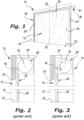
- FIGS 1 to 3 of the attached drawings show a roll-up door for industrial use according to the known prior art, indicated 10 as a whole.
- the roll-up door 10 of the so-called "high speed sliding" type, allows to close or open a passage 12 formed in a wall 14 by means of a flexible curtain 16 typically made of a plastic material or of a plasticized textile material.
- the aforementioned passage 12 which extends vertically between an upper crosspiece 20 and a lower base plane 22, or floor, as well as laterally between a pair of opposite vertical uprights 24 provided with respective straight and vertical guide rails 26 intended to be engaged slidably by the side edges of the curtain 16, allows two rooms to communicate upstream and downstream, respectively, of a portal structure 18 which delimits the passage 12.
- a roll-up door 10 of the type described above is used to close a room downstream the portal structure 18, in which a predetermined temperature significantly lower than the temperature of the room upstream of the portal structure 18, i.e. of the outer environment, as in the case of a cold room, in which the used curtain 16 may have a thermal insulation cavity.
- a roll-up door 10 of this type is frequently subject to the formation of a layer of moisture consisting of micro-droplets of water or a film of liquid on the surface of the curtain 16 facing the outer environment with a higher temperature, as a result of the condensation of the water vapor present in the air of this environment.
- the condensation water existing on the vertical portion of the curtain 16 flows by gravity towards the lower transversal edge of the curtain 16, when the latter rises and is wrapped up in the shelter area 28, causing an annoying fall of water on the floor below the roller shutter box 30 at the portal structure 18.
- the invention relates to a device for draining condensation water from a high speed sliding roll-up door interposed between two environments at different temperatures, of the type defined in the preamble of the attached claim 1.
- the object of the invention is to propose a simple and reliable device which allows to avoid the fall of the condensation water from the curtain towards the floor.
- the guide rails of the curtain comprise an upper rectilinear portion close to said shelter area, and a lower rectilinear portion offset with respect to the upper rectilinear portion, between which an S-shaped inclined portion is interposed, which is connected upstream and downstream with said upper and lower rectilinear portions by means of respective curved sections, a gutter formation being arranged below said upper rectilinear portion to receive by gravity the condensation water coming from the surface of said curtain during its raising step towards said shelter area.
- the inclined portion is inclined with respect to said upper and lower rectilinear portions by an angle between about 20° and 40°, preferably about 30°.
- the uprights of the portal structure can be made with a thickness only slightly greater than the thickness of the uprights of the traditional roll-up doors, so that the invention can be easily applied to roll-up doors which initially have the traditional structure, with just a few modifications within the reach of a skilled operator, during a periodic maintenance operation.
- the gutter formation consists of a substantially horizontal hollow section bar having a concavity facing upwards, the length of which is at least equal to the width of said curtain. This makes it possible to keep simple the structure of the gutter formation, and therefore of the entire condensation water draining device of the roll-up door.
- the center of the concavity of the section bar of the gutter formation is positioned substantially on the vertical axis of said upper rectilinear portion of said guide rails of the curtain. In this manner, the best operating efficiency of the condensation water draining device of the invention is obtained.
- Each of the side uprights 24 of the portal structure 18, in which a respective side edge of the curtain 16 is slidably mounted includes a respective guide rail 26 which comprises an upper rectilinear portion 26a, substantially vertical and close to the shelter area 28, and a lower rectilinear portion 26b substantially vertical and offset with respect to the upper rectilinear portion 26a, the portions 26a and 26b being substantially parallel and spaced apart.
- an inclined guide rail portion indicated by 26c having a general S-shape, being connected upstream with the respective upper rectilinear portion 26a, and downstream with the respective lower rectilinear portion 26b, by means of respective curved portions 26d and 26e.
- the inclined portion 26c forms an angle ⁇ between about 20° and 40°, preferably about 30°, with respect to the vertical of the upper rectilinear portion 26a, and of the lower rectilinear portion 26b which, as stated above, is substantially parallel to the upper portion 26a, so as not to significantly slow down the sliding speed of the curtain 16.
- a gutter formation 34 made by means of a hollow section bar, for example of metal or plastic material, arranged substantially horizontal and having the concavity facing upwards to receive by gravity the condensation water coming from the surface of the curtain 16, in particular during its raising step towards the shelter area 28.
- the gutter formation 34 which has a length at least equal to the width of the curtain 16, comprises a connection plate 34a which extends along one of its longitudinal sides to allow it to be fixed to the wall 14 facing the environment downstream with respect to the portal structure 18, by means of preferably removable fixing means 34b, such as nails or screws and relative anchors.
- the gutter formation 34 is conveniently arranged in such a manner that the center of the concavity of the relevant section bar is positioned substantially on the vertical of the upper rectilinear portion 26a of the guide rails 26, as shown in Figure 4 , in order to effectively collect the condensation water coming from this upper portion 26a.
- At least one longitudinal end portion of the gutter formation 34 is associated with a downspout 36 for draining the condensation water collected by the curtain 16 to the ground.
- the downpipe 36 can be made in such a way as to discharge the condensation water collected by the gutter formation 34, inside the lower rectilinear portion 26b of one or both of the drainage rails. guide 26.
- the motorized shaft arranged inside the "roller shutter box” 30 is actuated to wind the curtain 16 of the roll-up door 10a in the shelter area 28, dragging it towards its raised condition starting from the lowered condition shown in Figure 4 , so as to open the passage 12 defined by the portal structure 18.
- the condensation water in the gutter formation 34 can be easily discharged to the ground through one or more downspouts 36 made up of pipes of plastic or metal material.
- the curtain 16 At the end of the winding step of the curtain 16 as well as in the subsequent step of its unwinding from the shelter area 28, when it is lowered to close the passage 12 defined by the portal structure 18, the curtain 16 remains completely dry, which allows to avoid its damage over time due to moisture, and therefore to extend its service life.
Landscapes
- Engineering & Computer Science (AREA)
- Structural Engineering (AREA)
- Civil Engineering (AREA)
- Architecture (AREA)
- Operating, Guiding And Securing Of Roll- Type Closing Members (AREA)
- Processing Of Solid Wastes (AREA)
Abstract
Description
- The present invention refers in general to a high speed sliding roll-up doors for industrial use, which comprise a flexible curtain which, in the open condition of the door, is intended to be received in a shelter area placed above a portal structure which delimits a passage formed in a wall separating two adjacent rooms isolated by the door.
-
Figures 1 to 3 of the attached drawings show a roll-up door for industrial use according to the known prior art, indicated 10 as a whole. The roll-updoor 10, of the so-called "high speed sliding" type, allows to close or open apassage 12 formed in awall 14 by means of aflexible curtain 16 typically made of a plastic material or of a plasticized textile material. Theaforementioned passage 12, which extends vertically between anupper crosspiece 20 and alower base plane 22, or floor, as well as laterally between a pair of oppositevertical uprights 24 provided with respective straight andvertical guide rails 26 intended to be engaged slidably by the side edges of thecurtain 16, allows two rooms to communicate upstream and downstream, respectively, of aportal structure 18 which delimits thepassage 12. - Above the
portal structure 18 there is a shelter area for thecurtain 16, indicated by thereference number 28, delimited by a box-shaped cover casing 30, commonly called "roller shutter box", in which thecurtain 16 is stored in the its wrapped configuration, when thedoor 10 is in its open condition. For this purpose, in theshelter area 28 there is a rotatably mounted motorizedwinding shaft 32 parallel to theupper crossbar 20 of thestructure 18, on which thecurtain 16 is wound during its raising in the opening step of the roll-updoor 10. - Often, a roll-up
door 10 of the type described above is used to close a room downstream theportal structure 18, in which a predetermined temperature significantly lower than the temperature of the room upstream of theportal structure 18, i.e. of the outer environment, as in the case of a cold room, in which the usedcurtain 16 may have a thermal insulation cavity. - A roll-
up door 10 of this type is frequently subject to the formation of a layer of moisture consisting of micro-droplets of water or a film of liquid on the surface of thecurtain 16 facing the outer environment with a higher temperature, as a result of the condensation of the water vapor present in the air of this environment. - The condensation water existing on the vertical portion of the
curtain 16 flows by gravity towards the lower transversal edge of thecurtain 16, when the latter rises and is wrapped up in theshelter area 28, causing an annoying fall of water on the floor below theroller shutter box 30 at theportal structure 18. - More particularly, the invention relates to a device for draining condensation water from a high speed sliding roll-up door interposed between two environments at different temperatures, of the type defined in the preamble of the attached claim 1.
- The object of the invention is to propose a simple and reliable device which allows to avoid the fall of the condensation water from the curtain towards the floor.
- This object is achieved by a device having the features defined in the appended claims.
- In particular, according to the invention, the guide rails of the curtain comprise an upper rectilinear portion close to said shelter area, and a lower rectilinear portion offset with respect to the upper rectilinear portion, between which an S-shaped inclined portion is interposed, which is connected upstream and downstream with said upper and lower rectilinear portions by means of respective curved sections, a gutter formation being arranged below said upper rectilinear portion to receive by gravity the condensation water coming from the surface of said curtain during its raising step towards said shelter area. By virtue of these features, it is possible to almost completely eliminate the fallout of condensation water from the curtain of the roll-up closure to the floor, below the roller shutter box for sheltering the curtain.
- According to a preferred feature of the invention, the inclined portion is inclined with respect to said upper and lower rectilinear portions by an angle between about 20° and 40°, preferably about 30°.
- In this manner, the uprights of the portal structure can be made with a thickness only slightly greater than the thickness of the uprights of the traditional roll-up doors, so that the invention can be easily applied to roll-up doors which initially have the traditional structure, with just a few modifications within the reach of a skilled operator, during a periodic maintenance operation.
- According to another preferred feature of the invention, the gutter formation consists of a substantially horizontal hollow section bar having a concavity facing upwards, the length of which is at least equal to the width of said curtain. This makes it possible to keep simple the structure of the gutter formation, and therefore of the entire condensation water draining device of the roll-up door.
- Preferably, and according to yet another preferred feature of the invention, the center of the concavity of the section bar of the gutter formation is positioned substantially on the vertical axis of said upper rectilinear portion of said guide rails of the curtain. In this manner, the best operating efficiency of the condensation water draining device of the invention is obtained.
- Further characteristics and advantages of the invention will become clearer from the following detailed description, provided by way of nonlimiting example and referred to the attached drawings in which:
-
Figure 1 is a schematic perspective view of a roll-up door according to the prior art with its curtain in the completely lowered condition in which it closes a passage delimited by a portal structure associated with a wall separating two rooms at different temperatures, -
Figure 2 is a schematic side elevation view of the door ofFigure 1 from the side of line II-II, in which the surface of the curtain facing the outer environment has a layer of condensation water, -
Figure 3 is a view similar toFigure 2 showing the related roll-up door with its curtain in the raised condition at the end of the raising step of the curtain and its rolling up in the shelter area, -
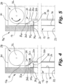
Figure 4 is a view similar to that ofFigure 2 , showing a roll-up door provided with the device of the invention with its curtain in the fully lowered condition, and -
Figure 5 is a view similar to that ofFigure 3 , of a roll-up door provided with the device of the invention, with its curtain in the fully raised condition. - In
Figures 4 and 5 of the drawings, in which reference numbers equal or similar to those employed above forFigures 1 to 3 have been used to indicate parts equal or similar to them, a highspeed roll-up door indicated byreference 10a is shown, which is placed between two environments at different temperatures and provided with a device for draining the condensation water according to the invention. In particular, the elements ofFigures 4 and 5 already described for a roll-up door of the prior art will generally not be described again. - Each of the side uprights 24 of the
portal structure 18, in which a respective side edge of thecurtain 16 is slidably mounted, includes arespective guide rail 26 which comprises an upperrectilinear portion 26a, substantially vertical and close to theshelter area 28, and a lowerrectilinear portion 26b substantially vertical and offset with respect to the upperrectilinear portion 26a, theportions - Between the
rectilinear portions rectilinear portion 26a, and downstream with the respective lowerrectilinear portion 26b, by means of respectivecurved portions inclined portion 26c forms an angle α between about 20° and 40°, preferably about 30°, with respect to the vertical of the upperrectilinear portion 26a, and of the lowerrectilinear portion 26b which, as stated above, is substantially parallel to theupper portion 26a, so as not to significantly slow down the sliding speed of thecurtain 16. - Below the upper
rectilinear portion 26a of therails 26 there is agutter formation 34 made by means of a hollow section bar, for example of metal or plastic material, arranged substantially horizontal and having the concavity facing upwards to receive by gravity the condensation water coming from the surface of thecurtain 16, in particular during its raising step towards theshelter area 28. - The
gutter formation 34, which has a length at least equal to the width of thecurtain 16, comprises aconnection plate 34a which extends along one of its longitudinal sides to allow it to be fixed to thewall 14 facing the environment downstream with respect to theportal structure 18, by means of preferably removable fixing means 34b, such as nails or screws and relative anchors. - The
gutter formation 34 is conveniently arranged in such a manner that the center of the concavity of the relevant section bar is positioned substantially on the vertical of the upperrectilinear portion 26a of theguide rails 26, as shown inFigure 4 , in order to effectively collect the condensation water coming from thisupper portion 26a. - Preferably, at least one longitudinal end portion of the
gutter formation 34 is associated with adownspout 36 for draining the condensation water collected by thecurtain 16 to the ground. - As an alternative, and according to a modification not shown in the figures, the
downpipe 36 can be made in such a way as to discharge the condensation water collected by thegutter formation 34, inside the lowerrectilinear portion 26b of one or both of the drainage rails.guide 26. - In the operation of the device of the invention, the motorized shaft arranged inside the "roller shutter box" 30 is actuated to wind the
curtain 16 of the roll-updoor 10a in theshelter area 28, dragging it towards its raised condition starting from the lowered condition shown inFigure 4 , so as to open thepassage 12 defined by theportal structure 18. - When on the surface of the
curtain 16, in its lowered configuration closing thepassage 12, there is condensation water, in particular on its surface facing the outer environment, this falls from thecurtain 16 by gravity and accumulates on thegutter formation 34. - Although a small part of the condensation water present on the
curtain 16 can descend in the direction identified by the lowerrectilinear portion 26b of therails 26 when thecurtain 16 is in the lowered condition, the raising step of thecurtain 16 is so rapid that practically thecurtain 16 almost instantaneously moves to the raised condition shown inFigure 5 , in which the portion of thecurtain 16 not wound on the winding shaft of the "roller shutter box" 30 is entirely above thegutter formation 34, whereby this condensation water falls by gravity into the gutter formation 34 (seeFigure 5 ). - The condensation water in the
gutter formation 34 can be easily discharged to the ground through one ormore downspouts 36 made up of pipes of plastic or metal material. - At the end of the winding step of the
curtain 16 as well as in the subsequent step of its unwinding from theshelter area 28, when it is lowered to close thepassage 12 defined by theportal structure 18, thecurtain 16 remains completely dry, which allows to avoid its damage over time due to moisture, and therefore to extend its service life.
Claims (9)
- Condensation water draining device for a high speed sliding roll-up door interposed between two rooms at different temperatures, which roll-up door (10) includes a flexible curtain (16) for closing or opening a passage (12) formed in a wall (14) separating said rooms and delimited by a portal structure (18) including a pair of side uprights (24) provided with guide rails (26) for the curtain (16), and an upper crosspiece (20), said curtain (16) having side edges adapted to slidably engage said guide rails (26) and being intended to be received, in the open condition of the door (10), in a shelter area (28) arranged above the portal structure (18),
characterized in that said guide rails (26) of the curtain (16) comprise an upper rectilinear portion (26a) close to said shelter area (28), and a lower rectilinear portion (26b) offset with respect to the upper rectilinear portion (26a), between which an S-shaped inclined portion (26c) is interposed, which is connected upstream and downstream with said upper and lower rectilinear portions (26a, 26b) by means of respective curved sections (26d, 26e), a gutter formation (34) being arranged below the upper rectilinear portion (26a) to receive by gravity the condensation water coming from the surface of said curtain (16) during its raising step towards said shelter area (28). - Device according to claim 1, characterized in that said upper and lower rectilinear portions (26a, 26b) of the guide rails (26) for the curtain (16) are parallel and vertical.
- Device according to claim 1 or 2, characterized in that said inclined portion (26c) is inclined with respect to said upper and lower rectilinear portions (26a, 26b) by an angle (α) comprised between about 20° and 40°, preferably of about 30°.
- Device according to any one of claims 1 to 3, characterized in that said gutter formation (34) consists of a substantially horizontal hollow section bar having a concavity facing upwards, the length of which is at least equal to the width of said curtain (16).
- Device according to claim 4, characterized in that said gutter formation (34) has a connection plate (34a) to be connected to said wall (14) for separating said rooms, by means of preferably removable fastening means (34b).
- Device according to claim 4 or 5, characterized in that the center of the concavity of the section bar of said gutter formation (34) is positioned substantially on the vertical axis of said upper rectilinear portion (26a) of said guide rails (26) of the curtain (16).
- Device according to any one of claims 1 to 6, characterized in that it comprises at least one downspout (36) for draining to the ground the condensation water collected into said gutter formation (34).
- Device according to claim 7, characterized in that said downspout (36) is made in such a manner as to drain the condensation water collected by said gutter formation (34) inside said lower rectilinear portion (26b) of at least one guide rail (26).
- High speed sliding roll-up door interposed between two rooms at different temperatures, having a condensation water draining device according to any one of claims 1 to 8.
Applications Claiming Priority (1)
| Application Number | Priority Date | Filing Date | Title |
|---|---|---|---|
| IT102021000030011A IT202100030011A1 (en) | 2021-11-26 | 2021-11-26 | CONDENSATION WATER DISPOSAL DEVICE OF A QUICK SLIDING ROLLER DOOR PLACED BETWEEN TWO ROOMS WITH DIFFERENT TEMPERATURES |
Publications (2)
| Publication Number | Publication Date |
|---|---|
| EP4187053A1 true EP4187053A1 (en) | 2023-05-31 |
| EP4187053B1 EP4187053B1 (en) | 2025-06-11 |
Family
ID=80225332
Family Applications (1)
| Application Number | Title | Priority Date | Filing Date |
|---|---|---|---|
| EP22020578.5A Active EP4187053B1 (en) | 2021-11-26 | 2022-11-24 | High speed sliding roll-up door interposed between two rooms at different temperatures with a condensation water draining device |
Country Status (5)
| Country | Link |
|---|---|
| US (1) | US12276157B2 (en) |
| EP (1) | EP4187053B1 (en) |
| ES (1) | ES3037260T3 (en) |
| IT (1) | IT202100030011A1 (en) |
| PT (1) | PT4187053T (en) |
Families Citing this family (2)
| Publication number | Priority date | Publication date | Assignee | Title |
|---|---|---|---|---|
| JP7615556B2 (en) * | 2020-07-31 | 2025-01-17 | 積水ハウス株式会社 | Building structure |
| US12612822B1 (en) * | 2024-03-22 | 2026-04-28 | Michael Murray | Adjustable screen hood assembly for sloped roof structures |
Citations (3)
| Publication number | Priority date | Publication date | Assignee | Title |
|---|---|---|---|---|
| DE202009011324U1 (en) * | 2009-08-20 | 2009-12-17 | Adolf Seuster Gmbh & Co. Kg | Gate with gully |
| US20110283620A1 (en) * | 2009-01-28 | 2011-11-24 | Rytec Corporation | Method and device for preventing contamination from a door which opens vertically |
| US20180119482A1 (en) * | 2016-08-05 | 2018-05-03 | Osi Industries, Llc | Drainage assembly for an automatic door |
Family Cites Families (31)
| Publication number | Priority date | Publication date | Assignee | Title |
|---|---|---|---|---|
| US3292685A (en) * | 1963-09-09 | 1966-12-20 | Guaranteed Weather Inc | Weatherproof retractable wall |
| US3734161A (en) * | 1970-08-26 | 1973-05-22 | E Pierce | Door construction |
| US4018259A (en) * | 1971-01-25 | 1977-04-19 | Dynamit Nobel Aktiengesellschaft | Jalousie element |
| US3840061A (en) * | 1971-01-25 | 1974-10-08 | G Herms | Jalousie element |
| US4524814A (en) * | 1983-06-22 | 1985-06-25 | Deziel Edward W | Enclosure assembly |
| US5027494A (en) | 1989-06-05 | 1991-07-02 | Martin Door Manufacturing, Inc. | Method of adjustably applying tension to a garage door |
| AU624505B2 (en) * | 1990-01-22 | 1992-06-11 | Sanwa Shutter Corporation | Shutter assembly for a bay window |
| DE4015214A1 (en) * | 1990-05-11 | 1991-11-14 | Efaflex Transport Lager | Lifting gate |
| US5484007A (en) * | 1990-05-11 | 1996-01-16 | Rejc; Gabrijel | Vertical lift gate with strip cladding in guideways |
| GB2299021B (en) * | 1995-03-22 | 1999-08-25 | Rasontec Nv | Curtain,end bar and guide bar |
| ES2194831T3 (en) * | 1997-07-25 | 2003-12-01 | Rytec Corp | DOOR-ELEVATED CURTAIN COIL FOR SANITARY APPLICATIONS. |
| US20030213180A1 (en) * | 2002-05-20 | 2003-11-20 | Shiro Ueda | Waterproof device for a rolling barrier |
| US8302353B2 (en) * | 2004-10-15 | 2012-11-06 | Thomas Bren | Water intrusion prevention method and apparatus |
| US7464743B1 (en) | 2005-10-24 | 2008-12-16 | Berger Jr Allen | Roll formed roll-up door guide with double wind bar end |
| US8627606B2 (en) | 2005-12-30 | 2014-01-14 | Tyto Life LLC | Combined sealing system for garage door |
| EP1956179A1 (en) * | 2007-02-07 | 2008-08-13 | Dynaco International S.A. | Device with a shutter that can roll around a drum. |
| US9440100B2 (en) | 2007-06-22 | 2016-09-13 | Mckeon Rolling Steel Door Co., Inc. | Fire and/or smoke blocking device |
| WO2012009022A2 (en) | 2010-07-16 | 2012-01-19 | Mortier Lester L | Overhead door with spring-loaded roller hinges |
| DE102012104039A1 (en) | 2012-05-08 | 2013-11-14 | Efaflex Inzeniring D.O.O. Ljubljana | Hubtoranordnung and Torsturz-sealing device for this purpose |
| US9428955B2 (en) * | 2013-03-15 | 2016-08-30 | Jacob Fleischman | Retractable wall system |
| CA2902241A1 (en) * | 2013-03-15 | 2014-09-18 | Jacob FLEISCHMAN | Retractable wall system and adaptor components |
| US9022089B1 (en) * | 2013-05-20 | 2015-05-05 | William S. Dau | Window with retractable barrier assembly |
| AU2015281286B2 (en) * | 2014-06-26 | 2019-05-16 | Assa Abloy Entrance Systems Ab | Sealing device for sealing a gap between a lintel and a roller shutter and a roller shutter with such a sealing device |
| FR3024177B1 (en) | 2014-07-25 | 2016-08-05 | Somfy Sas | METHOD FOR CONTROLLING THE OPERATION OF A MOTORIZED DRIVE DEVICE OF A DOMOTIC CLOSURE OR SOLAR PROTECTION INSTALLATION AND DEVICE THEREFOR |
| FR3046685A1 (en) | 2016-01-08 | 2017-07-14 | Somfy Sas | DOMOTIC INSTALLATION AND CONTROL METHOD THEREFOR |
| US11725453B2 (en) | 2018-02-28 | 2023-08-15 | John Koshar | Pest barricade |
| US11719040B2 (en) | 2018-04-05 | 2023-08-08 | Seuster Kg | Door comprising a guide arrangement |
| US10851544B1 (en) * | 2020-01-07 | 2020-12-01 | Dee Volin | Multi-function wind-directing leaf-separating-and-discharging rainwater-sealing automatic-multi-screen-raising-and-lowering multi-screen-securing fruit-drying-and-sorting truck-tonneau-covering rainwater-channeling-and-collecting leaf-filtering height-and-angle-adjustable louvered pergola |
| US11873678B2 (en) | 2020-11-03 | 2024-01-16 | Andrew S. Hoezee | Magnetic smart seal for overhead garage door |
| IT202000027621A1 (en) * | 2020-11-18 | 2022-05-18 | Bmpeurope S R L | RAPID-SLIDING ROLLER DOOR INTENDED TO BE INTERPOSED BETWEEN TWO ROOMS WITH DIFFERENT TEMPERATURES. |
| IT202100029690A1 (en) * | 2021-11-24 | 2023-05-24 | Bmpeurope S R L | IMPROVEMENTS OF AN AIR SEAL DEVICE FOR A LIFTING CLOSURE |
-
2021
- 2021-11-26 IT IT102021000030011A patent/IT202100030011A1/en unknown
-
2022
- 2022-11-15 US US17/987,430 patent/US12276157B2/en active Active
- 2022-11-24 EP EP22020578.5A patent/EP4187053B1/en active Active
- 2022-11-24 ES ES22020578T patent/ES3037260T3/en active Active
- 2022-11-24 PT PT220205785T patent/PT4187053T/en unknown
Patent Citations (3)
| Publication number | Priority date | Publication date | Assignee | Title |
|---|---|---|---|---|
| US20110283620A1 (en) * | 2009-01-28 | 2011-11-24 | Rytec Corporation | Method and device for preventing contamination from a door which opens vertically |
| DE202009011324U1 (en) * | 2009-08-20 | 2009-12-17 | Adolf Seuster Gmbh & Co. Kg | Gate with gully |
| US20180119482A1 (en) * | 2016-08-05 | 2018-05-03 | Osi Industries, Llc | Drainage assembly for an automatic door |
Also Published As
| Publication number | Publication date |
|---|---|
| US20230167677A1 (en) | 2023-06-01 |
| US12276157B2 (en) | 2025-04-15 |
| ES3037260T3 (en) | 2025-09-30 |
| PT4187053T (en) | 2025-07-25 |
| IT202100030011A1 (en) | 2023-05-26 |
| EP4187053B1 (en) | 2025-06-11 |
Similar Documents
| Publication | Publication Date | Title |
|---|---|---|
| EP4187053B1 (en) | High speed sliding roll-up door interposed between two rooms at different temperatures with a condensation water draining device | |
| JP2541394Y2 (en) | Thermal insulation shutter device | |
| US3503169A (en) | Self-draining window sill | |
| US9957749B2 (en) | Sealing device for sealing a gap between a lintel and a roller shutter and a roller shutter with such a sealing device | |
| EP0495682A2 (en) | Sliding door sill construction | |
| US20180010387A1 (en) | Hidden Insect Screen System for Double Hung, Tilt-to-Clean Windows | |
| CN101684716A (en) | Roll-up shutter with tiltable slots | |
| EP3214236A1 (en) | Kit for making a panel structure for an external side wall or a covering of a building, and building provided with such panel structure | |
| US1823514A (en) | Storm sash construction | |
| KR200331502Y1 (en) | Window Frame | |
| NL1034948C2 (en) | Greenhouse, has gutter comprising second profile for rainwater drainage and third profile above it for roof inspection walkway or window washing device transport rail | |
| KR20190062810A (en) | Gasket assembling structure for smooth drainage and draft protection of the door frame with sliding door opening system | |
| US1659786A (en) | Ventilator | |
| BE1015475A5 (en) | Device for shading and ventilation. | |
| PL228158B1 (en) | Window set, in particular roof window, with the fresh air diffuser | |
| JP5739389B2 (en) | Houses for continuous cultivation | |
| KR101158808B1 (en) | Ventilating control system for a roof | |
| JP7621188B2 (en) | Switchgear mounting structure and switchgear rainwater collector | |
| KR101877331B1 (en) | Sliding window comprising guide member | |
| EP2090735A1 (en) | Thermal insulation device for inbuilt rolling shutters | |
| RU182562U1 (en) | FIRE DOOR ROLL DOORS | |
| KR20060043153A (en) | Flat sash | |
| JPH0336702Y2 (en) | ||
| JP2500366Y2 (en) | Drainage device for shutter | |
| JP3745699B2 (en) | Greenhouse skylight |
Legal Events
| Date | Code | Title | Description |
|---|---|---|---|
| PUAI | Public reference made under article 153(3) epc to a published international application that has entered the european phase |
Free format text: ORIGINAL CODE: 0009012 |
|
| STAA | Information on the status of an ep patent application or granted ep patent |
Free format text: STATUS: THE APPLICATION HAS BEEN PUBLISHED |
|
| AK | Designated contracting states |
Kind code of ref document: A1 Designated state(s): AL AT BE BG CH CY CZ DE DK EE ES FI FR GB GR HR HU IE IS IT LI LT LU LV MC ME MK MT NL NO PL PT RO RS SE SI SK SM TR |
|
| P01 | Opt-out of the competence of the unified patent court (upc) registered |
Effective date: 20230603 |
|
| STAA | Information on the status of an ep patent application or granted ep patent |
Free format text: STATUS: REQUEST FOR EXAMINATION WAS MADE |
|
| 17P | Request for examination filed |
Effective date: 20231124 |
|
| RBV | Designated contracting states (corrected) |
Designated state(s): AL AT BE BG CH CY CZ DE DK EE ES FI FR GB GR HR HU IE IS IT LI LT LU LV MC ME MK MT NL NO PL PT RO RS SE SI SK SM TR |
|
| GRAP | Despatch of communication of intention to grant a patent |
Free format text: ORIGINAL CODE: EPIDOSNIGR1 |
|
| STAA | Information on the status of an ep patent application or granted ep patent |
Free format text: STATUS: GRANT OF PATENT IS INTENDED |
|
| INTG | Intention to grant announced |
Effective date: 20250107 |
|
| GRAS | Grant fee paid |
Free format text: ORIGINAL CODE: EPIDOSNIGR3 |
|
| GRAA | (expected) grant |
Free format text: ORIGINAL CODE: 0009210 |
|
| STAA | Information on the status of an ep patent application or granted ep patent |
Free format text: STATUS: THE PATENT HAS BEEN GRANTED |
|
| AK | Designated contracting states |
Kind code of ref document: B1 Designated state(s): AL AT BE BG CH CY CZ DE DK EE ES FI FR GB GR HR HU IE IS IT LI LT LU LV MC ME MK MT NL NO PL PT RO RS SE SI SK SM TR |
|
| REG | Reference to a national code |
Ref country code: GB Ref legal event code: FG4D |
|
| REG | Reference to a national code |
Ref country code: CH Ref legal event code: EP |
|
| REG | Reference to a national code |
Ref country code: DE Ref legal event code: R096 Ref document number: 602022015681 Country of ref document: DE |
|
| REG | Reference to a national code |
Ref country code: IE Ref legal event code: FG4D |
|
| REG | Reference to a national code |
Ref country code: PT Ref legal event code: SC4A Ref document number: 4187053 Country of ref document: PT Date of ref document: 20250725 Kind code of ref document: T Free format text: AVAILABILITY OF NATIONAL TRANSLATION Effective date: 20250721 |
|
| PGFP | Annual fee paid to national office [announced via postgrant information from national office to epo] |
Ref country code: NL Payment date: 20250716 Year of fee payment: 4 |
|
| REG | Reference to a national code |
Ref country code: NL Ref legal event code: FP |
|
| REG | Reference to a national code |
Ref country code: ES Ref legal event code: FG2A Ref document number: 3037260 Country of ref document: ES Kind code of ref document: T3 Effective date: 20250930 |
|
| PG25 | Lapsed in a contracting state [announced via postgrant information from national office to epo] |
Ref country code: FI Free format text: LAPSE BECAUSE OF FAILURE TO SUBMIT A TRANSLATION OF THE DESCRIPTION OR TO PAY THE FEE WITHIN THE PRESCRIBED TIME-LIMIT Effective date: 20250611 |
|
| PGFP | Annual fee paid to national office [announced via postgrant information from national office to epo] |
Ref country code: PT Payment date: 20250801 Year of fee payment: 4 |
|
| REG | Reference to a national code |
Ref country code: LT Ref legal event code: MG9D |
|
| PG25 | Lapsed in a contracting state [announced via postgrant information from national office to epo] |
Ref country code: GR Free format text: LAPSE BECAUSE OF FAILURE TO SUBMIT A TRANSLATION OF THE DESCRIPTION OR TO PAY THE FEE WITHIN THE PRESCRIBED TIME-LIMIT Effective date: 20250912 Ref country code: NO Free format text: LAPSE BECAUSE OF FAILURE TO SUBMIT A TRANSLATION OF THE DESCRIPTION OR TO PAY THE FEE WITHIN THE PRESCRIBED TIME-LIMIT Effective date: 20250911 |
|
| PGFP | Annual fee paid to national office [announced via postgrant information from national office to epo] |
Ref country code: TR Payment date: 20250730 Year of fee payment: 4 |
|
| PG25 | Lapsed in a contracting state [announced via postgrant information from national office to epo] |
Ref country code: BG Free format text: LAPSE BECAUSE OF FAILURE TO SUBMIT A TRANSLATION OF THE DESCRIPTION OR TO PAY THE FEE WITHIN THE PRESCRIBED TIME-LIMIT Effective date: 20250611 |
|
| PG25 | Lapsed in a contracting state [announced via postgrant information from national office to epo] |
Ref country code: HR Free format text: LAPSE BECAUSE OF FAILURE TO SUBMIT A TRANSLATION OF THE DESCRIPTION OR TO PAY THE FEE WITHIN THE PRESCRIBED TIME-LIMIT Effective date: 20250611 |
|
| PG25 | Lapsed in a contracting state [announced via postgrant information from national office to epo] |
Ref country code: RS Free format text: LAPSE BECAUSE OF FAILURE TO SUBMIT A TRANSLATION OF THE DESCRIPTION OR TO PAY THE FEE WITHIN THE PRESCRIBED TIME-LIMIT Effective date: 20250911 |
|
| PG25 | Lapsed in a contracting state [announced via postgrant information from national office to epo] |
Ref country code: LV Free format text: LAPSE BECAUSE OF FAILURE TO SUBMIT A TRANSLATION OF THE DESCRIPTION OR TO PAY THE FEE WITHIN THE PRESCRIBED TIME-LIMIT Effective date: 20250611 |
|
| REG | Reference to a national code |
Ref country code: CH Ref legal event code: U11 Free format text: ST27 STATUS EVENT CODE: U-0-0-U10-U11 (AS PROVIDED BY THE NATIONAL OFFICE) Effective date: 20251201 |
|
| REG | Reference to a national code |
Ref country code: AT Ref legal event code: MK05 Ref document number: 1802405 Country of ref document: AT Kind code of ref document: T Effective date: 20250611 |
|
| PG25 | Lapsed in a contracting state [announced via postgrant information from national office to epo] |
Ref country code: IS Free format text: LAPSE BECAUSE OF FAILURE TO SUBMIT A TRANSLATION OF THE DESCRIPTION OR TO PAY THE FEE WITHIN THE PRESCRIBED TIME-LIMIT Effective date: 20251011 |
|
| PGFP | Annual fee paid to national office [announced via postgrant information from national office to epo] |
Ref country code: DE Payment date: 20251128 Year of fee payment: 4 |
|
| PG25 | Lapsed in a contracting state [announced via postgrant information from national office to epo] |
Ref country code: AT Free format text: LAPSE BECAUSE OF FAILURE TO SUBMIT A TRANSLATION OF THE DESCRIPTION OR TO PAY THE FEE WITHIN THE PRESCRIBED TIME-LIMIT Effective date: 20250611 Ref country code: SM Free format text: LAPSE BECAUSE OF FAILURE TO SUBMIT A TRANSLATION OF THE DESCRIPTION OR TO PAY THE FEE WITHIN THE PRESCRIBED TIME-LIMIT Effective date: 20250611 |
|
| PGFP | Annual fee paid to national office [announced via postgrant information from national office to epo] |
Ref country code: IT Payment date: 20251201 Year of fee payment: 4 |
|
| PGFP | Annual fee paid to national office [announced via postgrant information from national office to epo] |
Ref country code: FR Payment date: 20251120 Year of fee payment: 4 |
|
| PGFP | Annual fee paid to national office [announced via postgrant information from national office to epo] |
Ref country code: BE Payment date: 20251124 Year of fee payment: 4 |
|
| PGFP | Annual fee paid to national office [announced via postgrant information from national office to epo] |
Ref country code: CH Payment date: 20251201 Year of fee payment: 4 |
|
| PG25 | Lapsed in a contracting state [announced via postgrant information from national office to epo] |
Ref country code: CZ Free format text: LAPSE BECAUSE OF FAILURE TO SUBMIT A TRANSLATION OF THE DESCRIPTION OR TO PAY THE FEE WITHIN THE PRESCRIBED TIME-LIMIT Effective date: 20250611 |
|
| PG25 | Lapsed in a contracting state [announced via postgrant information from national office to epo] |
Ref country code: PL Free format text: LAPSE BECAUSE OF FAILURE TO SUBMIT A TRANSLATION OF THE DESCRIPTION OR TO PAY THE FEE WITHIN THE PRESCRIBED TIME-LIMIT Effective date: 20250611 |
|
| PG25 | Lapsed in a contracting state [announced via postgrant information from national office to epo] |
Ref country code: EE Free format text: LAPSE BECAUSE OF FAILURE TO SUBMIT A TRANSLATION OF THE DESCRIPTION OR TO PAY THE FEE WITHIN THE PRESCRIBED TIME-LIMIT Effective date: 20250611 |
|
| PG25 | Lapsed in a contracting state [announced via postgrant information from national office to epo] |
Ref country code: SK Free format text: LAPSE BECAUSE OF FAILURE TO SUBMIT A TRANSLATION OF THE DESCRIPTION OR TO PAY THE FEE WITHIN THE PRESCRIBED TIME-LIMIT Effective date: 20250611 |
|
| PGFP | Annual fee paid to national office [announced via postgrant information from national office to epo] |
Ref country code: ES Payment date: 20251203 Year of fee payment: 4 |
|
| PG25 | Lapsed in a contracting state [announced via postgrant information from national office to epo] |
Ref country code: RO Free format text: LAPSE BECAUSE OF FAILURE TO SUBMIT A TRANSLATION OF THE DESCRIPTION OR TO PAY THE FEE WITHIN THE PRESCRIBED TIME-LIMIT Effective date: 20250611 |
|
| REG | Reference to a national code |
Ref country code: DE Ref legal event code: R097 Ref document number: 602022015681 Country of ref document: DE |
|
| PG25 | Lapsed in a contracting state [announced via postgrant information from national office to epo] |
Ref country code: DK Free format text: LAPSE BECAUSE OF FAILURE TO SUBMIT A TRANSLATION OF THE DESCRIPTION OR TO PAY THE FEE WITHIN THE PRESCRIBED TIME-LIMIT Effective date: 20250611 |
|
| PLBE | No opposition filed within time limit |
Free format text: ORIGINAL CODE: 0009261 |
|
| STAA | Information on the status of an ep patent application or granted ep patent |
Free format text: STATUS: NO OPPOSITION FILED WITHIN TIME LIMIT |
|
| REG | Reference to a national code |
Ref country code: CH Ref legal event code: L10 Free format text: ST27 STATUS EVENT CODE: U-0-0-L10-L00 (AS PROVIDED BY THE NATIONAL OFFICE) Effective date: 20260423 |
|
| 26N | No opposition filed |
Effective date: 20260312 |
|
| PG25 | Lapsed in a contracting state [announced via postgrant information from national office to epo] |
Ref country code: LT Free format text: LAPSE BECAUSE OF FAILURE TO SUBMIT A TRANSLATION OF THE DESCRIPTION OR TO PAY THE FEE WITHIN THE PRESCRIBED TIME-LIMIT Effective date: 20250611 |
|
| PG25 | Lapsed in a contracting state [announced via postgrant information from national office to epo] |
Ref country code: MC Free format text: LAPSE BECAUSE OF FAILURE TO SUBMIT A TRANSLATION OF THE DESCRIPTION OR TO PAY THE FEE WITHIN THE PRESCRIBED TIME-LIMIT Effective date: 20250611 |
|
| PG25 | Lapsed in a contracting state [announced via postgrant information from national office to epo] |
Ref country code: LU Free format text: LAPSE BECAUSE OF NON-PAYMENT OF DUE FEES Effective date: 20251124 |
|
| PG25 | Lapsed in a contracting state [announced via postgrant information from national office to epo] |
Ref country code: SE Free format text: LAPSE BECAUSE OF FAILURE TO SUBMIT A TRANSLATION OF THE DESCRIPTION OR TO PAY THE FEE WITHIN THE PRESCRIBED TIME-LIMIT Effective date: 20250611 |