EP4186796B1 - Trennstreifen für einstellbares eisschutzsystem - Google Patents
Trennstreifen für einstellbares eisschutzsystem Download PDFInfo
- Publication number
- EP4186796B1 EP4186796B1 EP22210025.7A EP22210025A EP4186796B1 EP 4186796 B1 EP4186796 B1 EP 4186796B1 EP 22210025 A EP22210025 A EP 22210025A EP 4186796 B1 EP4186796 B1 EP 4186796B1
- Authority
- EP
- European Patent Office
- Prior art keywords
- parting strip
- strip section
- section
- airflow
- heating
- Prior art date
- Legal status (The legal status is an assumption and is not a legal conclusion. Google has not performed a legal analysis and makes no representation as to the accuracy of the status listed.)
- Active
Links
Images




Classifications
-
- B—PERFORMING OPERATIONS; TRANSPORTING
- B64—AIRCRAFT; AVIATION; COSMONAUTICS
- B64D—EQUIPMENT FOR FITTING IN OR TO AIRCRAFT; FLIGHT SUITS; PARACHUTES; ARRANGEMENT OR MOUNTING OF POWER PLANTS OR PROPULSION TRANSMISSIONS IN AIRCRAFT
- B64D15/00—De-icing or preventing icing on exterior surfaces of aircraft
- B64D15/12—De-icing or preventing icing on exterior surfaces of aircraft by electric heating
-
- B—PERFORMING OPERATIONS; TRANSPORTING
- B64—AIRCRAFT; AVIATION; COSMONAUTICS
- B64D—EQUIPMENT FOR FITTING IN OR TO AIRCRAFT; FLIGHT SUITS; PARACHUTES; ARRANGEMENT OR MOUNTING OF POWER PLANTS OR PROPULSION TRANSMISSIONS IN AIRCRAFT
- B64D15/00—De-icing or preventing icing on exterior surfaces of aircraft
- B64D15/12—De-icing or preventing icing on exterior surfaces of aircraft by electric heating
- B64D15/14—De-icing or preventing icing on exterior surfaces of aircraft by electric heating controlled cyclically along length of surface
-
- B—PERFORMING OPERATIONS; TRANSPORTING
- B64—AIRCRAFT; AVIATION; COSMONAUTICS
- B64D—EQUIPMENT FOR FITTING IN OR TO AIRCRAFT; FLIGHT SUITS; PARACHUTES; ARRANGEMENT OR MOUNTING OF POWER PLANTS OR PROPULSION TRANSMISSIONS IN AIRCRAFT
- B64D15/00—De-icing or preventing icing on exterior surfaces of aircraft
- B64D15/20—Means for detecting icing or initiating de-icing
Definitions
- the present disclosure relates to de-icing systems for aircraft, and more particularly, to aircraft electrothermal ice protection systems.
- Aircrafts implement de-icing systems to remove ice accumulation on a critical surface of the aircraft such as for example, a wing, horizontal stabilizer, engine, pylons, and/or a blade to name a few surfaces.
- An example of an aircraft de-icing system includes an electrothermal ice protection system (IPS), which utilizes one or more high-watt density parting strips disposed at one or more ice stagnation areas of the critical surface.
- IPS electrothermal ice protection system
- the parting strips can be heated in response to receiving electrical current, thereby facilitating anti-icing (e.g., prevent the formation of ice) and/or removal of accumulated ice, ideally from an area of maximum dynamic pressure location on the leading edge of the critical surface.
- anti-icing e.g., prevent the formation of ice
- removal of accumulated ice ideally from an area of maximum dynamic pressure location on the leading edge of the critical surface.
- aerodynamic forces realized by the critical surface during aircraft flight assists to remove or "shed” remaining portions of accumulated ice from locations of the critical surface farther aft, thereby allowing for a reduction of ice-removing electrothermal power (de-icing) and enhancing shedding performance in those other zones of ice protection.
- EP 0 680 878 A1 describes an electrothermal deicing system.
- GB 2 479 943 A describes a method of calibrating a heater system.
- US 2008/029648 A2 describes an aircraft wing with electrothermal deicing.
- An electrothermal ice protection system (IPS) installed on an aircraft is defined in claim 1 and includes a sensor, a parting strip assembly, and a controller.
- the sensor monitors a direction of a local incident airflow that is imparted on the sensor.
- the parting strip assembly is coupled to the critical surface and includes a plurality of heating sections.
- the controller is in signal communication with the sensor and the parting strip assembly. The controller determines a direction of surface airflow incident on a critical surface of the aircraft based on the local incident airflow and selectively concentrates power to at least one targeted heating section among the plurality of heating sections with respect to non-targeted heating sections among the plurality of heating sections based on the direction of the airflow.
- a parting strip assembly is configured to be installed at one or more critical surfaces of an aircraft.
- the parting strip assembly comprises a middle parting strip section, a lower parting strip section, and an upper parting strip section.
- the middle parting strip is configured to contact a middle portion of the critical surface
- the lower parting strip section is configured to contact a lower portion of the critical surface
- the upper parting strip section is configured to an upper portion of the critical surface.
- the middle parting strip section, the lower parting strip section, and the upper parting strip section are activated in response to receiving a concentration of power, wherein the at least one middle parting strip section, the at least one lower parting strip section, and the at least one upper parting strip section are configured to be activated independently from one another.
- a method of de-icing a critical surface of an aircraft comprises determining a plurality of heating zones on a critical surface of the aircraft and coupling a parting strip to the critical surface such that a plurality of heating section of the parting strip correspond to the plurality of heating zones.
- the method further comprises monitoring, via a sensor, a direction of a local airflow imparted on the sensor and determining, via a controller, a direction of surface airflow incident on the critical surface based on the direction of the local airflow imparted on the sensor.
- the method further comprises selectively activating, via the controller, the plurality of heating sections independently from one another by concentrating electrical power to at least one targeted heating section among the plurality of heating sections with respect to non-targeted heating sections among the plurality of heating sections based on the direction of the airflow.
- a conventional electrical or electrical mechanical IPS utilizes a single strip at a fixed location, sometimes referred to as a "parting strip zone".
- the parting strip or multiple heaters are all energized together simultaneously so as to uniformly heat the parting strip zone, regardless as to the actual location of accumulated ice. Consequently, conventional IPS designs do not optimize power consumption.
- a parting strip assembly that includes multiple parting strips that define respective parting strip zones.
- One or more targeted parting strip zones can be heated independently from one another based on the angle of airflow with respect to the critical surface. Accordingly, a targeted parting strip zone can be selected to be heated and can dynamically change based on changes to the location of maximum dynamic pressure as it varies with aircraft angle of attack (AOA), the airspeed, the configuration of high-lift devices, and/or other parameters.
- AOA aircraft angle of attack
- one or more non-limiting embodiments allows for selectively heating targeted parting strips without heating other parting strips, thereby providing an optimized electrothermal IPS capable of operating with improved power efficiency.
- an aircraft 10 equipped with an optimized electrothermal ice protection system (IPS) 14 is illustrated according to a non-limiting embodiment.
- the aircraft 10 includes a critical surface 12 that can be heated by the electrothermal IPS 14.
- the critical surface 12 is described going forward as a wing, for example, it should be appreciated that the critical surface may also include, but is not limited to, an airfoil, a blade or any curved leading edge surface.
- the electrothermal IPS 14 includes one or more sensors 22, a parting strip assembly 15, and a controller 50.
- the electrothermal IPS 14 is configured to remove ice from a leading edge 18 of wing 12.
- the electrothermal IPS 14 provides heat to leading edge 18 so as to melt ice accreted thereto.
- leading edge 18 of wing 12 is depicted as being ice free, due to the ice removal capability of the electrothermal IPS 14, ice accumulation 20 is shown at stagnation areas located aft of the electrothermal IPS 14.
- sensors 22 can perform various types of sensing functions and measurements including, but not limited to, temperature measurement, atmospheric pressure measurement, airflow speed measurement, and airflow direction measurement.
- the sensors 22 include a probe that extends out from the aircraft 10 (e.g., the side of the fuselage), thereby exposing the surface region to the atmosphere adjacent to the aircraft 10.
- Various technologies can be used to detect ice accumulation on the exposed sensors 22.
- a resonant probe can be used to detect ice accumulation upon these surface regions.
- the resonant probe can have a resonant frequency change that is indicative of ice accumulation upon the surface region of sensor 22 which correlates to ice accumulation on the critical surfaces of the aircraft 10.
- two adjacent conductors can be located on the surface regions of parting strip assembly 15 such that the conductors are exposed to the atmosphere adjacent to wing 12. When water or ice accretes on the surface region and spans two adjacent conductors, the conductivity therebetween can be indicative of such conditions.
- a temperature sensor located in proximity to the surface sensor can be used to differentiate between detection of water and ice.
- the sensors 22 are configured to monitor a direction of incident airflow correlated to the direction of airflow incident on a critical surface 12 of the aircraft 10.
- the incidence travel can be described as the variation of the incidence along the critical surface 12 (e.g., wing) during flight of the aircraft 10.
- airflow angles close to the surfaces of an aircraft 10 are affected by boundary layer effects and may not be the same as the true airflow angle of the aircraft 10 relative to free stream conditions.
- Some sensors 22 may be capable of sensing what is known as a local AOA or local airflow angle (i.e., the airflow angle at the localized area of the sensor) but may not be capable of provide an accurate measurement of the local airflow angle at other critical locations on the aircraft 10. Therefore, an accurate determination of the local airflow angle at other critical locations on the aircraft may involve determining a correlation between the local sensed airflow angle and the local critical surface airflow angle. Accordingly, the sensors 22 can operate together with the controller to provide a local and specific information of the incidence.
- the airflow angle at the localized area of a sensor 22 can be delivered to the controller 50, which then determines a correlation (e.g., through arithmetic calculations and/or using a predetermined look-up table stored in memory) between the local airflow angle and the direction of airflow incident on a critical surface 12 of the aircraft 10.
- a correlation e.g., through arithmetic calculations and/or using a predetermined look-up table stored in memory
- the electrothermal IPS 14, parting strip assembly 15, and sensors 22 are in signal communication with a controller 50.
- the controller 50 can control various operations of the electrothermal IPS 14.
- the controller 50 controls operation of the parting strip assembly 15 based on one or more signals provided by the sensors 22.
- the controller can control a power supply (not depicted) to output electrical current to the parting strip assembly 15 based on a signal indicating ice accumulation detected by one or more of the sensors 22.
- the current induces the parting strip assembly 15 to emit heat, thereby melting the ice.
- the sensors 22 can determine a direction of airflow with respect to wing 12.
- the controller 50 can activate a section of the parting strip assembly 15 to heat a targeted zone of the wing 12, while deactivating other sections of the parting strip assembly 15. In this manner, the power efficiency of the electrothermal IPS 14 can be improved as described in greater detail below.
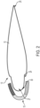
- FIGS. 2 and 3 collectively illustrate a parting strip assembly 15 capable of heating a critical surface such as wing 12.
- the wing 12 has a main body 13 extending between a trailing edge 25 and a leading edge 27.
- the main body 13 has a recess 29 can be formed gradually by tapering, or can alternatively be formed by a step in the reduction of thickness.
- the parting strip assembly 15 is configured to be disposed against an outer surface 30 of the leading edge 27 of the wing 12.
- the parting strip assembly 15 can be sized and shaped so that it fits snugly within this recessed section 29 of the main body 13.
- the outer surface of the parting strip assembly 15 is flush with the outer surface 30 of the wing 12 so that the surfaces are flush with each other and there is no step between their outer surfaces.
- the parting strip assembly 15 covers at least part of the leading edge 27 of the wing 12.
- the part of the wing 12 covered by the parting strip assembly 15 can include an expected ice stagnation area.
- the parting strip assembly 15 covers the upper surface, middle surface and lower surface of the wing 12 to define a heating zone 100 as shown in FIG. 3 .
- the parting strip assembly 15 includes one or more parting strips, where each parting strip serves as a heating element.
- the parting strips are embedded in a resin or other matrix that provides anti-erosion protection and also serves as a thermal insulation layer.
- one or more of the parting strips include a strip of metallic foil that is resistive and generates heat when connected to an electric power supply by the Joule Effect.
- Other heating elements and matrices can be employed without departing from the scope of the invention.
- the parting strip assembly 15 includes a plurality of individual parting strip sections.
- the parting strip assembly 15 includes a lower parting strip section 102, a middle parting strip section 104, and an upper parting strip section 106.
- the lower parting strip section 102 can define a lower heating zone
- the middle parting strip section 104 can define a middle heating zone
- the upper parting strip section 106 can define an upper heating zone.
- the lower parting strip section 102, middle parting strip section 104, and upper parting strip section 106 are in signal communication with the controller 50 and each can be independently activated and deactivated with respect to one another.
- a given parting strip section 102, 104 106 can be activated by concentrating power to the given section given section 102, 104 106.
- the controller 50 can activate the middle parting strip section 104 without activating the lower parting strip section 102 and the upper parting strip section 106.
- the controller 50 can activate a combination of the parting strip sections 102, 104 and 106.
- the controller 50 can activate the lower parting strip section 102 and the middle parting strip section 104 without activating the upper parting strip section 106. If necessary, the controller 50 can activate all of the lower parting strip section 102, the middle parting strip section 104, and the upper parting strip section 106 simultaneously.
- the controller 50 can provide a higher power level to one parting strip section 102, 104, 106, while providing a lower power level to one or more of the other parting strip sections 102, 104, 106.
- the controller 50 can adjust the power levels (e.g., the power density) for a given parting strip section 102, 104, 106 based on the local AOA at the parting strip, while one or more targeted parting strip sections 102, 104, 106 to be controlled (e.g., thermally adjusted) for power optimization.
- the range of incident airflow angles over the flight envelope of the aircraft is used to locate and size the different parting strips.
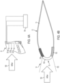
- the parting strip assembly 15 is illustrated heating a middle heating zone 105 in response to detecting airflow 150 incident to the wing 12 at a first direction (e.g., in a forward direction) according to a non-limiting embodiment.
- a first direction e.g., in a forward direction
- the controller 50 can receive the output signal from the sensor 22 to determine the direction of the airflow 150 at any given moment during the flight of the aircraft.
- the forward direction of the airflow 150 incident on the middle of the middle area of the wing 12 is often the area of maximum dynamic pressure during typical flight conditions of an aircraft. Accordingly, the middle heating zone 105 is determined to be the optimum zone to be heated based on the current location of maximum dynamic pressure applied by the airflow 150. As described herein, the controller 50 can selectively heat the middle heating zone 105 by activating the middle parting strip section 104 (e.g., by delivering electrical current to the middle parting strip section 104) while deactivating the lower parting strip section 102 and the upper parting strip section 106 (e.g., by refraining from delivering current to the lower and upper parting strip sections 102 and 106).
- the middle parting strip section 104 e.g., by delivering electrical current to the middle parting strip section 104
- deactivating the lower parting strip section 102 and the upper parting strip section 106 e.g., by refraining from delivering current to the lower and upper parting strip sections 102 and 106.
- the parting strip assembly 15 is illustrated heating the lower heating zone 103 in response to detecting airflow 150 incident to the wing 12 at a second direction (e.g., in an upward direction) according to a non-limiting embodiment.
- the direction of the airflow 150 actively changes from the forward direction shown in FIGS. 4A and 4B to the upward direction 150 shown in FIG. 5 during the flight of the aircraft. This scenario is typical during a "hold condition" or during descent and/or landing events. Accordingly, the location of maximum dynamic pressure moves to a lower location on the wing 12.
- the controller can dynamically determine that the optimum zone to be heated is the lower heating zone 103. In this manner, the controller can dynamically stop heating the middle heating zone 105 by deactivating the middle parting strip section 104 (e.g., stopping current flow thereto), and initiate heating of the lower heating zone 103 by activating the lower parting strip section 102 (e.g., delivering current flow thereto), while deactivating the middle parting strip section 104 and the upper parting strip section 106 (e.g., by refraining from delivering current to the middle and upper parting strip sections 104 and 106).
- the controller can dynamically stop heating the middle heating zone 105 by deactivating the middle parting strip section 104 (e.g., stopping current flow thereto), and initiate heating of the lower heating zone 103 by activating the lower parting strip section 102 (e.g., delivering current flow thereto), while deactivating the middle parting strip section 104 and the upper parting strip section 106 (e.g., by refraining from delivering current to
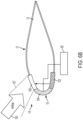
- the parting strip assembly 15 is illustrated heating the upper heating zone 107 in response to detecting airflow 150 incident to the wing 12 at a third direction (e.g., in a downward direction) according to a non-limiting embodiment.
- the direction of the airflow 150 actively changes direction (e.g., from the forward direction shown in FIGS. 4A and 4B ) to the downward direction 150 shown in FIGS. 6A and 6B during the flight of the aircraft. This scenario is typical during a descent. Accordingly, the location of maximum dynamic pressure moves to an upper location on the wing 12.
- the controller 50 can dynamically determine that the optimum zone to be heated is the upper heating zone 107. In this manner, the controller 50 can dynamically initiate heating of the upper heating zone 107 by activating the upper parting strip section 106 (e.g., delivering current flow thereto), while deactivating the lower parting strip section 102 and the middle parting strip section 104 (e.g., by refraining from delivering current to the lower and middle parting strip sections 102 and 104).
- the controller 50 can dynamically initiate heating of the upper heating zone 107 by activating the upper parting strip section 106 (e.g., delivering current flow thereto), while deactivating the lower parting strip section 102 and the middle parting strip section 104 (e.g., by refraining from delivering current to the lower and middle parting strip sections 102 and 104).
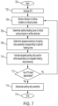
- the method begins at operation 700, and at operation 702 an electrothermal IPS installed on an aircraft is activated.
- a direction of airflow incident on a critical surface of an aircraft is monitored.
- the critical surface can include, but is not limited to, a wing, airfoil, and/or a blade.
- an optimal heating zone of the critical surface is determined based on the direction of the airflow.
- one or more targeted sections of a parting strip assembly are determined based on the optimal heating zone.
- the targeted section(s) of the parting strip assembly are activated while non-targeted sections of the parting strip assembly are de-activated or reduced in power. Accordingly, the optimal heating zone is heating using the activated sections of the parting strip assembly.
- a determination is made as to whether the electrothermal IPS has been deactivated. When the electrothermal IPS has been deactivated, the parting strip assembly is deactivated at operation 714 (e.g., current is halted to the targeted sections of the parting strip assembly), and the method ends at operation 716.
- the method returns to operation 704 and continues monitoring the direction of the airflow incident on the critical surface. It is typical for the aircraft to change direction, thus dynamically changing the direction of the airflow incident on the critical surface as described herein. For example, the direction of the airflow may change from a forward direction to an upward direction as the aircraft transitions from a cruise flight phase to a climb flight phase.
- a change in the direction of the airflow is determined at operation 704, a new optimal heating zone can be determined at operation 706, and one or more different targeted sections of the parting strip assembly can be dynamically activated based on the newly determined optimal heating zone. Accordingly, the new targeted sections of the parting strip can be activated to account for the change in the airflow direction, and the method continues to operation 712 as described above.
- various non-limiting embodiments of the present disclosure provides an electrothermal IPS capable of determining optimum heating zones, and in response selectively activating sections of a parting strip assembly as the location of maximum dynamic pressure varies with aircraft angle of attack (AOA), airspeed, configuration of high-lift devices, or other parameters.
- AOA aircraft angle of attack
- the electrothermal IPS facilitates optimized heating efficiency while reducing overall power consumption during the flight of the aircraft.
Landscapes
- Engineering & Computer Science (AREA)
- Aviation & Aerospace Engineering (AREA)
- Control Of Resistance Heating (AREA)
- Radiation Pyrometers (AREA)
Claims (11)
- Elektrothermisches Eisschutzsystem "IPS", das an einem Flugzeug installiert ist, wobei das elektrothermische IPS Folgendes umfasst:einen Sensor (22), der dazu konfiguriert ist, eine Richtung eines lokalen einfallenden Luftstroms, der auf den Sensor (22) einwirkt, zu überwachen;eine Trennstreifenanordnung, die an eine kritische Oberfläche einer Anströmkante eines Flügels des Flugzeugs gekoppelt ist, wobei die Trennstreifenanordnung eine Vielzahl von Heizbereichen beinhaltet; undeine Steuerung (50) in Signalverbindung mit dem Sensor (22) und der Trennstreifenanordnung, wobei die Steuerung (50) dazu konfiguriert ist, eine Richtung eines auf eine kritische Oberfläche des Flugzeugs einfallenden Oberflächenluftstroms basierend auf dem lokalen einfallenden Luftstrom zu bestimmen und basierend auf der Richtung des Oberflächenluftstroms selektiv Leistung auf mindestens einen anvisierten Heizbereich unter der Vielzahl von Heizbereichen in Bezug auf nicht anvisierte Heizbereiche unter der Vielzahl von Heizbereichen zu konzentrieren.
- Elektrothermisches IPS nach Anspruch 1, wobei die Steuerung (50) eine optimale Heizzone der kritischen Oberfläche basierend auf einem oder beiden von der Richtung des Oberflächenluftstroms und einer Eisstagnationsfläche der kritischen Oberfläche bestimmt und ein erstes Leistungsniveau an den mindestens einen anvisierten Bereich abgibt, um die optimale Heizzone zu erwärmen, während ein zweites Leistungsniveau, das niedriger ist als das erste Leistungsniveau, an mindestens einen der nicht anvisierten Bereiche abgegeben wird.
- Elektrothermisches IPS nach Anspruch 2, wobei die Vielzahl von Heizbereichen Folgendes umfasst:mindestens einen mittleren Trennstreifenbereich, der einen mittleren Abschnitt der kritischen Oberfläche berührt;mindestens einen unteren Trennstreifenbereich, der einen unteren Abschnitt der kritischen Oberfläche berührt; undmindestens einen oberen Trennstreifenbereich, der einen oberen Abschnitt der kritischen Oberfläche berührt.
- Elektrothermisches IPS nach Anspruch 3, wobei die Steuerung (50) basierend auf der Richtung des Oberflächenluftstroms mindestens einen von dem mittleren Trennstreifenbereich, dem mindestens einen unteren Trennstreifenbereich und dem mindestens einen oberen Trennstreifenbereich aktiviert, während mindestens einer von dem verbleibenden mittleren Trennstreifenbereich, dem mindestens einen unteren Trennstreifenbereich und dem mindestens einen oberen Trennstreifenbereich deaktiviert ist.
- Elektrothermisches IPS nach Anspruch 4, wobei die Steuerung (50) als Reaktion auf Erfassen des auf den mittleren Abschnitt der kritischen Oberfläche einfallenden Oberflächenluftstroms den mindestens einen mittleren Trennstreifenbereich aktiviert, während mindestens einer von dem unteren Trennstreifenbereich und dem mindestens einen oberen Trennstreifenbereich deaktiviert ist.
- Elektrothermisches IPS nach Anspruch 4, wobei die Steuerung (50) als Reaktion auf Erfassen des auf den unteren Abschnitt der kritischen Oberfläche einfallenden Oberflächenluftstroms den mindestens einen unteren Trennstreifenbereich aktiviert, während mindestens einer von dem mittleren Trennstreifenbereich und dem mindestens einen oberen Trennstreifenbereich deaktiviert ist.
- Elektrothermisches IPS nach Anspruch 4, wobei die Steuerung (50) als Reaktion auf Erfassen des auf den oberen Abschnitt der kritischen Oberfläche einfallenden Oberflächenluftstroms den mindestens einen oberen Trennstreifenbereich aktiviert, während mindestens einer von dem mittleren Trennstreifenbereich und dem mindestens einen oberen Trennstreifenbereich deaktiviert ist.
- Elektrothermisches IPS nach Anspruch 2, wobei die Steuerung (50) die Ausgabe von elektrischem Strom an den mindestens einen anvisierten Bereich steuert, um die Leistung an dem mindestens einen anvisierten Bereich zu konzentrieren, während die Ausgabe von elektrischem Strom an den mindestens einen der nicht anvisierten Bereiche blockiert ist, um den mindestens einen nicht anvisierten Bereich zu deaktivieren.
- Verfahren zum Enteisen eines Flugzeugs, wobei das Verfahren Folgendes umfasst:Bestimmen einer Vielzahl von Heizzonen an einer kritischen Oberfläche einer Anströmkante eines Flügels des Flugzeugs und Koppeln eines Trennstreifens an die kritische Oberfläche, sodass eine Vielzahl von Heizbereichen des Trennstreifens der Vielzahl von Heizzonen entspricht;Überwachen, über einen Sensor (22), einer Richtung eines auf den Sensor (22) einwirkenden lokalen Luftstroms; undBestimmen einer Richtung des auf die kritische Oberfläche einfallenden Oberflächenluftstroms über eine Steuerung (50) basierend auf der Richtung des auf den Sensor (22) einwirkenden lokalen Luftstroms; undselektives Aktivieren der Vielzahl von Heizbereichen unabhängig voneinander über die Steuerung (50) durch Konzentrieren von elektrischer Leistung auf mindestens einen anvisierten Heizbereich unter der Vielzahl von Heizbereichen in Bezug auf nicht anvisierte Heizbereiche unter der Vielzahl von Heizbereichen basierend auf der Richtung des Luftstroms.
- Verfahren nach Anspruch 9, wobei das selektive Aktivieren der Vielzahl von Heizbereichen unabhängig voneinander ferner Folgendes umfasst:Bestimmen einer optimalen Heizzone der kritischen Oberfläche basierend auf der Richtung des Oberflächenluftstroms und einer Stagnationsstelle; undAktivieren des mindestens einen anvisierten Bereichs zum Erwärmen der optimalen Heizzone bei gleichzeitigem Deaktivieren oder Bereitstellen einer geringeren Leistung an mindestens einen der nicht anvisierten Bereiche, oderwobei das selektive Aktivieren der Vielzahl von Heizbereichen unabhängig voneinander ferner Folgendes umfasst:
Aktivieren mindestens eines von dem mittleren Trennstreifenbereich, dem mindestens einen unteren Trennstreifenbereich und dem mindestens einen oberen Trennstreifenbereich, während mindestens einer von dem verbleibenden mittleren Trennstreifenbereich, dem mindestens einen unteren Trennstreifenbereich und dem mindestens einen oberen Trennstreifenbereich deaktiviert wird, basierend auf der Richtung des Oberflächenluftstroms, oder wobei das selektive Aktivieren der Vielzahl von Heizbereichen unabhängig voneinander ferner Folgendes umfasst:
Aktivieren des mindestens einen mittleren Trennstreifenbereichs, während mindestens ein unterer Trennstreifenbereich und der mindestens eine obere Trennstreifenbereich deaktiviert werden, als Reaktion auf Bestimmen des auf den mittleren Abschnitt der kritischen Oberfläche einfallenden Oberflächenluftstroms, oder wobei das selektive Aktivieren der Vielzahl von Heizbereichen unabhängig voneinander ferner Folgendes umfasst:
Aktivieren des mindestens einen unteren Trennstreifenbereichs, während mindestens ein mittlerer Trennstreifenbereich und der mindestens eine obere Trennstreifenbereich deaktiviert werden, als Reaktion auf Bestimmen des auf den unteren Abschnitt der kritischen Oberfläche einfallenden Oberflächenluftstroms, oder wobei das selektive Aktivieren der Vielzahl von Heizbereichen unabhängig voneinander ferner Folgendes umfasst:
Aktivieren des mindestens einen oberen Trennstreifenbereichs, während mindestens ein mittlerer Trennstreifenbereich und der mindestens eine untere Trennstreifenbereich deaktiviert werden, als Reaktion auf Bestimmen des auf den oberen Abschnitt der kritischen Oberfläche einfallenden Oberflächenluftstroms. - Verfahren nach Anspruch 9 oder 10, wobei das selektive Aktivieren der Vielzahl von Heizbereichen unabhängig voneinander ferner Ausgeben von elektrischem Strom über eine Steuerung (50) an den mindestens einen anvisierten Bereich umfasst, um die Leistung an dem mindestens einen anvisierten Bereich zu konzentrieren, während die Ausgabe von elektrischem Strom an den mindestens einen der nicht anvisierten Abschnitte blockiert wird, um den mindestens einen nicht anvisierten Bereich zu deaktivieren.
Applications Claiming Priority (1)
| Application Number | Priority Date | Filing Date | Title |
|---|---|---|---|
| US17/537,611 US11926425B2 (en) | 2021-11-30 | 2021-11-30 | Adjustable ice protection system parting strip |
Publications (2)
| Publication Number | Publication Date |
|---|---|
| EP4186796A1 EP4186796A1 (de) | 2023-05-31 |
| EP4186796B1 true EP4186796B1 (de) | 2025-01-29 |
Family
ID=84363789
Family Applications (1)
| Application Number | Title | Priority Date | Filing Date |
|---|---|---|---|
| EP22210025.7A Active EP4186796B1 (de) | 2021-11-30 | 2022-11-28 | Trennstreifen für einstellbares eisschutzsystem |
Country Status (3)
| Country | Link |
|---|---|
| US (2) | US11926425B2 (de) |
| EP (1) | EP4186796B1 (de) |
| CN (1) | CN116198729A (de) |
Families Citing this family (2)
| Publication number | Priority date | Publication date | Assignee | Title |
|---|---|---|---|---|
| US11926425B2 (en) | 2021-11-30 | 2024-03-12 | Goodrich Corporation | Adjustable ice protection system parting strip |
| CN117302546B (zh) * | 2023-11-15 | 2026-02-17 | 中航通飞华南飞机工业有限公司 | 一种具备测压功能的气囊除冰系统冰风洞试验装置及方法 |
Family Cites Families (14)
| Publication number | Priority date | Publication date | Assignee | Title |
|---|---|---|---|---|
| EP0459216A3 (en) | 1990-06-01 | 1993-03-17 | The Bfgoodrich Company | Electrical heater de-icer |
| CA2147084A1 (en) | 1994-04-13 | 1995-10-14 | Tommy Maurice Wilson, Jr. | Electrothermal deicing system |
| US6237874B1 (en) | 1997-09-22 | 2001-05-29 | Northcoast Technologies | Zoned aircraft de-icing system and method |
| US7278610B2 (en) | 2004-03-03 | 2007-10-09 | Goodrich Corporation | Aircraft wing with electrothermal deicing and/or anti-icing device |
| US7246773B2 (en) | 2004-05-06 | 2007-07-24 | Goodrich Coporation | Low power, pulsed, electro-thermal ice protection system |
| GB2450503A (en) * | 2007-06-26 | 2008-12-31 | Ultra Electronics Ltd | Ice protection system with plural heating elements |
| US7938368B2 (en) | 2008-04-07 | 2011-05-10 | United Technologies Corporation | Nosecone ice protection system for a gas turbine engine |
| GB0823121D0 (en) * | 2008-12-18 | 2009-01-28 | Penny & Giles Controls Ltd | Ice detection system |
| GB2479943B (en) | 2010-04-30 | 2015-03-11 | Ultra Electronics Ltd | Method of calibrating a heater system |
| CA2964260C (en) * | 2016-06-28 | 2025-08-26 | Rosemount Aerospace Inc. | AIR DATA DETECTION PROBE USING AN ICING STATE DETECTOR |
| US10775504B2 (en) * | 2016-09-29 | 2020-09-15 | Honeywell International Inc. | Laser air data sensor mounting and operation for eye safety |
| US11169173B2 (en) * | 2019-05-15 | 2021-11-09 | Rosemount Aerospace Inc. | Air data system architectures including laser air data and acoustic air data sensors |
| GB2589368B (en) * | 2019-11-29 | 2022-06-01 | Ultra Electronics Ltd | Apparatus and method for detecting water or ice |
| US11926425B2 (en) | 2021-11-30 | 2024-03-12 | Goodrich Corporation | Adjustable ice protection system parting strip |
-
2021
- 2021-11-30 US US17/537,611 patent/US11926425B2/en active Active
-
2022
- 2022-10-21 CN CN202211293234.0A patent/CN116198729A/zh active Pending
- 2022-11-28 EP EP22210025.7A patent/EP4186796B1/de active Active
-
2024
- 2024-03-11 US US18/601,353 patent/US12325524B2/en active Active
Also Published As
| Publication number | Publication date |
|---|---|
| US20230166849A1 (en) | 2023-06-01 |
| US11926425B2 (en) | 2024-03-12 |
| US12325524B2 (en) | 2025-06-10 |
| US20240217664A1 (en) | 2024-07-04 |
| EP4186796A1 (de) | 2023-05-31 |
| CN116198729A (zh) | 2023-06-02 |
Similar Documents
| Publication | Publication Date | Title |
|---|---|---|
| US12325524B2 (en) | Adjustable ice protection system parting strip | |
| EP2389314B1 (de) | Vereisungssensorsystem und verfahren | |
| US10018580B2 (en) | Apparatus and method for detecting water or ice | |
| EP2004488B1 (de) | Eisschutzsystem | |
| US9676485B2 (en) | Ice detection system and method | |
| EP3738882B1 (de) | Aerodynamikverbesserungsvorrichtung für ein flugzeug mit solch einer vorrichtung ausgestattetes flugzeug | |
| US9346550B2 (en) | Ice detection and mitigation device | |
| US7854412B2 (en) | Energy-efficient electro-thermal and electro-mechanical ice-protection method | |
| EP4065470B1 (de) | Vorrichtung und verfahren zur erkennung von wasser oder eis | |
| EP0749894A2 (de) | Elektrothermische Enteisungsvorrichtung | |
| US20160009400A1 (en) | Ice protection system | |
| WO2019160843A1 (en) | Ice formation detection and removal system for an aerial vehicle and method | |
| CA2822630A1 (en) | Ice protection system | |
| US11390387B2 (en) | De-icing system and method | |
| HK40042013A (en) | Apparatus and method for detecting water or ice |
Legal Events
| Date | Code | Title | Description |
|---|---|---|---|
| PUAI | Public reference made under article 153(3) epc to a published international application that has entered the european phase |
Free format text: ORIGINAL CODE: 0009012 |
|
| STAA | Information on the status of an ep patent application or granted ep patent |
Free format text: STATUS: THE APPLICATION HAS BEEN PUBLISHED |
|
| AK | Designated contracting states |
Kind code of ref document: A1 Designated state(s): AL AT BE BG CH CY CZ DE DK EE ES FI FR GB GR HR HU IE IS IT LI LT LU LV MC ME MK MT NL NO PL PT RO RS SE SI SK SM TR |
|
| P01 | Opt-out of the competence of the unified patent court (upc) registered |
Effective date: 20230922 |
|
| STAA | Information on the status of an ep patent application or granted ep patent |
Free format text: STATUS: REQUEST FOR EXAMINATION WAS MADE |
|
| 17P | Request for examination filed |
Effective date: 20231130 |
|
| RBV | Designated contracting states (corrected) |
Designated state(s): AL AT BE BG CH CY CZ DE DK EE ES FI FR GB GR HR HU IE IS IT LI LT LU LV MC ME MK MT NL NO PL PT RO RS SE SI SK SM TR |
|
| GRAP | Despatch of communication of intention to grant a patent |
Free format text: ORIGINAL CODE: EPIDOSNIGR1 |
|
| STAA | Information on the status of an ep patent application or granted ep patent |
Free format text: STATUS: GRANT OF PATENT IS INTENDED |
|
| RIC1 | Information provided on ipc code assigned before grant |
Ipc: B64D 15/20 20060101ALI20240809BHEP Ipc: B64D 15/12 20060101AFI20240809BHEP |
|
| INTG | Intention to grant announced |
Effective date: 20240827 |
|
| GRAS | Grant fee paid |
Free format text: ORIGINAL CODE: EPIDOSNIGR3 |
|
| GRAA | (expected) grant |
Free format text: ORIGINAL CODE: 0009210 |
|
| STAA | Information on the status of an ep patent application or granted ep patent |
Free format text: STATUS: THE PATENT HAS BEEN GRANTED |
|
| AK | Designated contracting states |
Kind code of ref document: B1 Designated state(s): AL AT BE BG CH CY CZ DE DK EE ES FI FR GB GR HR HU IE IS IT LI LT LU LV MC ME MK MT NL NO PL PT RO RS SE SI SK SM TR |
|
| REG | Reference to a national code |
Ref country code: GB Ref legal event code: FG4D |
|
| REG | Reference to a national code |
Ref country code: CH Ref legal event code: EP |
|
| REG | Reference to a national code |
Ref country code: DE Ref legal event code: R096 Ref document number: 602022010074 Country of ref document: DE |
|
| REG | Reference to a national code |
Ref country code: IE Ref legal event code: FG4D |
|
| REG | Reference to a national code |
Ref country code: NL Ref legal event code: MP Effective date: 20250129 |
|
| PG25 | Lapsed in a contracting state [announced via postgrant information from national office to epo] |
Ref country code: NL Free format text: LAPSE BECAUSE OF FAILURE TO SUBMIT A TRANSLATION OF THE DESCRIPTION OR TO PAY THE FEE WITHIN THE PRESCRIBED TIME-LIMIT Effective date: 20250129 |
|
| PG25 | Lapsed in a contracting state [announced via postgrant information from national office to epo] |
Ref country code: RS Free format text: LAPSE BECAUSE OF FAILURE TO SUBMIT A TRANSLATION OF THE DESCRIPTION OR TO PAY THE FEE WITHIN THE PRESCRIBED TIME-LIMIT Effective date: 20250429 |
|
| PG25 | Lapsed in a contracting state [announced via postgrant information from national office to epo] |
Ref country code: FI Free format text: LAPSE BECAUSE OF FAILURE TO SUBMIT A TRANSLATION OF THE DESCRIPTION OR TO PAY THE FEE WITHIN THE PRESCRIBED TIME-LIMIT Effective date: 20250129 |
|
| PG25 | Lapsed in a contracting state [announced via postgrant information from national office to epo] |
Ref country code: PL Free format text: LAPSE BECAUSE OF FAILURE TO SUBMIT A TRANSLATION OF THE DESCRIPTION OR TO PAY THE FEE WITHIN THE PRESCRIBED TIME-LIMIT Effective date: 20250129 |
|
| PG25 | Lapsed in a contracting state [announced via postgrant information from national office to epo] |
Ref country code: ES Free format text: LAPSE BECAUSE OF FAILURE TO SUBMIT A TRANSLATION OF THE DESCRIPTION OR TO PAY THE FEE WITHIN THE PRESCRIBED TIME-LIMIT Effective date: 20250129 |
|
| REG | Reference to a national code |
Ref country code: LT Ref legal event code: MG9D |
|
| PG25 | Lapsed in a contracting state [announced via postgrant information from national office to epo] |
Ref country code: NO Free format text: LAPSE BECAUSE OF FAILURE TO SUBMIT A TRANSLATION OF THE DESCRIPTION OR TO PAY THE FEE WITHIN THE PRESCRIBED TIME-LIMIT Effective date: 20250429 Ref country code: IS Free format text: LAPSE BECAUSE OF FAILURE TO SUBMIT A TRANSLATION OF THE DESCRIPTION OR TO PAY THE FEE WITHIN THE PRESCRIBED TIME-LIMIT Effective date: 20250529 |
|
| REG | Reference to a national code |
Ref country code: AT Ref legal event code: MK05 Ref document number: 1763238 Country of ref document: AT Kind code of ref document: T Effective date: 20250129 |
|
| PG25 | Lapsed in a contracting state [announced via postgrant information from national office to epo] |
Ref country code: HR Free format text: LAPSE BECAUSE OF FAILURE TO SUBMIT A TRANSLATION OF THE DESCRIPTION OR TO PAY THE FEE WITHIN THE PRESCRIBED TIME-LIMIT Effective date: 20250129 |
|
| PG25 | Lapsed in a contracting state [announced via postgrant information from national office to epo] |
Ref country code: LV Free format text: LAPSE BECAUSE OF FAILURE TO SUBMIT A TRANSLATION OF THE DESCRIPTION OR TO PAY THE FEE WITHIN THE PRESCRIBED TIME-LIMIT Effective date: 20250129 Ref country code: PT Free format text: LAPSE BECAUSE OF FAILURE TO SUBMIT A TRANSLATION OF THE DESCRIPTION OR TO PAY THE FEE WITHIN THE PRESCRIBED TIME-LIMIT Effective date: 20250529 |
|
| PG25 | Lapsed in a contracting state [announced via postgrant information from national office to epo] |
Ref country code: BG Free format text: LAPSE BECAUSE OF FAILURE TO SUBMIT A TRANSLATION OF THE DESCRIPTION OR TO PAY THE FEE WITHIN THE PRESCRIBED TIME-LIMIT Effective date: 20250129 Ref country code: GR Free format text: LAPSE BECAUSE OF FAILURE TO SUBMIT A TRANSLATION OF THE DESCRIPTION OR TO PAY THE FEE WITHIN THE PRESCRIBED TIME-LIMIT Effective date: 20250430 |
|
| PG25 | Lapsed in a contracting state [announced via postgrant information from national office to epo] |
Ref country code: AT Free format text: LAPSE BECAUSE OF FAILURE TO SUBMIT A TRANSLATION OF THE DESCRIPTION OR TO PAY THE FEE WITHIN THE PRESCRIBED TIME-LIMIT Effective date: 20250129 |
|
| PG25 | Lapsed in a contracting state [announced via postgrant information from national office to epo] |
Ref country code: SE Free format text: LAPSE BECAUSE OF FAILURE TO SUBMIT A TRANSLATION OF THE DESCRIPTION OR TO PAY THE FEE WITHIN THE PRESCRIBED TIME-LIMIT Effective date: 20250129 |
|
| PG25 | Lapsed in a contracting state [announced via postgrant information from national office to epo] |
Ref country code: SM Free format text: LAPSE BECAUSE OF FAILURE TO SUBMIT A TRANSLATION OF THE DESCRIPTION OR TO PAY THE FEE WITHIN THE PRESCRIBED TIME-LIMIT Effective date: 20250129 |
|
| PG25 | Lapsed in a contracting state [announced via postgrant information from national office to epo] |
Ref country code: DK Free format text: LAPSE BECAUSE OF FAILURE TO SUBMIT A TRANSLATION OF THE DESCRIPTION OR TO PAY THE FEE WITHIN THE PRESCRIBED TIME-LIMIT Effective date: 20250129 |
|
| PG25 | Lapsed in a contracting state [announced via postgrant information from national office to epo] |
Ref country code: IT Free format text: LAPSE BECAUSE OF FAILURE TO SUBMIT A TRANSLATION OF THE DESCRIPTION OR TO PAY THE FEE WITHIN THE PRESCRIBED TIME-LIMIT Effective date: 20250129 |
|
| PG25 | Lapsed in a contracting state [announced via postgrant information from national office to epo] |
Ref country code: CZ Free format text: LAPSE BECAUSE OF FAILURE TO SUBMIT A TRANSLATION OF THE DESCRIPTION OR TO PAY THE FEE WITHIN THE PRESCRIBED TIME-LIMIT Effective date: 20250129 Ref country code: EE Free format text: LAPSE BECAUSE OF FAILURE TO SUBMIT A TRANSLATION OF THE DESCRIPTION OR TO PAY THE FEE WITHIN THE PRESCRIBED TIME-LIMIT Effective date: 20250129 |
|
| PG25 | Lapsed in a contracting state [announced via postgrant information from national office to epo] |
Ref country code: RO Free format text: LAPSE BECAUSE OF FAILURE TO SUBMIT A TRANSLATION OF THE DESCRIPTION OR TO PAY THE FEE WITHIN THE PRESCRIBED TIME-LIMIT Effective date: 20250129 |
|
| PG25 | Lapsed in a contracting state [announced via postgrant information from national office to epo] |
Ref country code: SK Free format text: LAPSE BECAUSE OF FAILURE TO SUBMIT A TRANSLATION OF THE DESCRIPTION OR TO PAY THE FEE WITHIN THE PRESCRIBED TIME-LIMIT Effective date: 20250129 |
|
| REG | Reference to a national code |
Ref country code: DE Ref legal event code: R097 Ref document number: 602022010074 Country of ref document: DE |
|
| PLBE | No opposition filed within time limit |
Free format text: ORIGINAL CODE: 0009261 |
|
| STAA | Information on the status of an ep patent application or granted ep patent |
Free format text: STATUS: NO OPPOSITION FILED WITHIN TIME LIMIT |
|
| 26N | No opposition filed |
Effective date: 20251030 |
|
| PGFP | Annual fee paid to national office [announced via postgrant information from national office to epo] |
Ref country code: DE Payment date: 20251022 Year of fee payment: 4 |
|
| PGFP | Annual fee paid to national office [announced via postgrant information from national office to epo] |
Ref country code: FR Payment date: 20251022 Year of fee payment: 4 |