EP4186758A1 - Control method for hydraulic retarder, and control system - Google Patents
Control method for hydraulic retarder, and control system Download PDFInfo
- Publication number
- EP4186758A1 EP4186758A1 EP20946026.0A EP20946026A EP4186758A1 EP 4186758 A1 EP4186758 A1 EP 4186758A1 EP 20946026 A EP20946026 A EP 20946026A EP 4186758 A1 EP4186758 A1 EP 4186758A1
- Authority
- EP
- European Patent Office
- Prior art keywords
- vehicle
- denotes
- hydraulic retarder
- ahead
- oil
- Prior art date
- Legal status (The legal status is an assumption and is not a legal conclusion. Google has not performed a legal analysis and makes no representation as to the accuracy of the status listed.)
- Granted
Links
Images

Classifications
-
- B—PERFORMING OPERATIONS; TRANSPORTING
- B60—VEHICLES IN GENERAL
- B60T—VEHICLE BRAKE CONTROL SYSTEMS OR PARTS THEREOF; BRAKE CONTROL SYSTEMS OR PARTS THEREOF, IN GENERAL; ARRANGEMENT OF BRAKING ELEMENTS ON VEHICLES IN GENERAL; PORTABLE DEVICES FOR PREVENTING UNWANTED MOVEMENT OF VEHICLES; VEHICLE MODIFICATIONS TO FACILITATE COOLING OF BRAKES
- B60T10/00—Control or regulation for continuous braking making use of fluid or powdered medium, e.g. for use when descending a long slope
-
- B—PERFORMING OPERATIONS; TRANSPORTING
- B60—VEHICLES IN GENERAL
- B60T—VEHICLE BRAKE CONTROL SYSTEMS OR PARTS THEREOF; BRAKE CONTROL SYSTEMS OR PARTS THEREOF, IN GENERAL; ARRANGEMENT OF BRAKING ELEMENTS ON VEHICLES IN GENERAL; PORTABLE DEVICES FOR PREVENTING UNWANTED MOVEMENT OF VEHICLES; VEHICLE MODIFICATIONS TO FACILITATE COOLING OF BRAKES
- B60T1/00—Arrangements of braking elements, i.e. of those parts where braking effect occurs specially for vehicles
- B60T1/02—Arrangements of braking elements, i.e. of those parts where braking effect occurs specially for vehicles acting by retarding wheels
- B60T1/08—Arrangements of braking elements, i.e. of those parts where braking effect occurs specially for vehicles acting by retarding wheels using fluid or powdered medium
- B60T1/087—Arrangements of braking elements, i.e. of those parts where braking effect occurs specially for vehicles acting by retarding wheels using fluid or powdered medium in hydrodynamic, i.e. non-positive displacement, retarders
-
- B—PERFORMING OPERATIONS; TRANSPORTING
- B60—VEHICLES IN GENERAL
- B60K—ARRANGEMENT OR MOUNTING OF PROPULSION UNITS OR OF TRANSMISSIONS IN VEHICLES; ARRANGEMENT OR MOUNTING OF PLURAL DIVERSE PRIME-MOVERS IN VEHICLES; AUXILIARY DRIVES FOR VEHICLES; INSTRUMENTATION OR DASHBOARDS FOR VEHICLES; ARRANGEMENTS IN CONNECTION WITH COOLING, AIR INTAKE, GAS EXHAUST OR FUEL SUPPLY OF PROPULSION UNITS IN VEHICLES
- B60K31/00—Vehicle fittings, acting on a single sub-unit only, for automatically controlling vehicle speed, i.e. preventing speed from exceeding an arbitrarily established velocity or maintaining speed at a particular velocity, as selected by the vehicle operator
- B60K31/06—Vehicle fittings, acting on a single sub-unit only, for automatically controlling vehicle speed, i.e. preventing speed from exceeding an arbitrarily established velocity or maintaining speed at a particular velocity, as selected by the vehicle operator including fluid pressure actuated servomechanism in which the vehicle velocity affecting element is actuated by fluid pressure
-
- B—PERFORMING OPERATIONS; TRANSPORTING
- B60—VEHICLES IN GENERAL
- B60T—VEHICLE BRAKE CONTROL SYSTEMS OR PARTS THEREOF; BRAKE CONTROL SYSTEMS OR PARTS THEREOF, IN GENERAL; ARRANGEMENT OF BRAKING ELEMENTS ON VEHICLES IN GENERAL; PORTABLE DEVICES FOR PREVENTING UNWANTED MOVEMENT OF VEHICLES; VEHICLE MODIFICATIONS TO FACILITATE COOLING OF BRAKES
- B60T10/00—Control or regulation for continuous braking making use of fluid or powdered medium, e.g. for use when descending a long slope
- B60T10/02—Control or regulation for continuous braking making use of fluid or powdered medium, e.g. for use when descending a long slope with hydrodynamic brake
-
- F—MECHANICAL ENGINEERING; LIGHTING; HEATING; WEAPONS; BLASTING
- F16—ENGINEERING ELEMENTS AND UNITS; GENERAL MEASURES FOR PRODUCING AND MAINTAINING EFFECTIVE FUNCTIONING OF MACHINES OR INSTALLATIONS; THERMAL INSULATION IN GENERAL
- F16D—COUPLINGS FOR TRANSMITTING ROTATION; CLUTCHES; BRAKES
- F16D57/00—Liquid-resistance brakes; Brakes using the internal friction of fluids or fluid-like media, e.g. powders
- F16D57/02—Liquid-resistance brakes; Brakes using the internal friction of fluids or fluid-like media, e.g. powders with blades or like members braked by the fluid
-
- F—MECHANICAL ENGINEERING; LIGHTING; HEATING; WEAPONS; BLASTING
- F16—ENGINEERING ELEMENTS AND UNITS; GENERAL MEASURES FOR PRODUCING AND MAINTAINING EFFECTIVE FUNCTIONING OF MACHINES OR INSTALLATIONS; THERMAL INSULATION IN GENERAL
- F16D—COUPLINGS FOR TRANSMITTING ROTATION; CLUTCHES; BRAKES
- F16D57/00—Liquid-resistance brakes; Brakes using the internal friction of fluids or fluid-like media, e.g. powders
- F16D57/04—Liquid-resistance brakes; Brakes using the internal friction of fluids or fluid-like media, e.g. powders with blades causing a directed flow, e.g. Föttinger type
-
- B—PERFORMING OPERATIONS; TRANSPORTING
- B60—VEHICLES IN GENERAL
- B60T—VEHICLE BRAKE CONTROL SYSTEMS OR PARTS THEREOF; BRAKE CONTROL SYSTEMS OR PARTS THEREOF, IN GENERAL; ARRANGEMENT OF BRAKING ELEMENTS ON VEHICLES IN GENERAL; PORTABLE DEVICES FOR PREVENTING UNWANTED MOVEMENT OF VEHICLES; VEHICLE MODIFICATIONS TO FACILITATE COOLING OF BRAKES
- B60T2201/00—Particular use of vehicle brake systems; Special systems using also the brakes; Special software modules within the brake system controller
- B60T2201/04—Hill descent control
-
- B—PERFORMING OPERATIONS; TRANSPORTING
- B60—VEHICLES IN GENERAL
- B60T—VEHICLE BRAKE CONTROL SYSTEMS OR PARTS THEREOF; BRAKE CONTROL SYSTEMS OR PARTS THEREOF, IN GENERAL; ARRANGEMENT OF BRAKING ELEMENTS ON VEHICLES IN GENERAL; PORTABLE DEVICES FOR PREVENTING UNWANTED MOVEMENT OF VEHICLES; VEHICLE MODIFICATIONS TO FACILITATE COOLING OF BRAKES
- B60T2210/00—Detection or estimation of road or environment conditions; Detection or estimation of road shapes
- B60T2210/20—Road shapes
-
- B—PERFORMING OPERATIONS; TRANSPORTING
- B60—VEHICLES IN GENERAL
- B60W—CONJOINT CONTROL OF VEHICLE SUB-UNITS OF DIFFERENT TYPE OR DIFFERENT FUNCTION; CONTROL SYSTEMS SPECIALLY ADAPTED FOR HYBRID VEHICLES; ROAD VEHICLE DRIVE CONTROL SYSTEMS FOR PURPOSES NOT RELATED TO THE CONTROL OF A PARTICULAR SUB-UNIT
- B60W10/00—Conjoint control of vehicle sub-units of different type or different function
- B60W10/18—Conjoint control of vehicle sub-units of different type or different function including control of braking systems
- B60W10/196—Conjoint control of vehicle sub-units of different type or different function including control of braking systems acting within the driveline, e.g. retarders
-
- B—PERFORMING OPERATIONS; TRANSPORTING
- B60—VEHICLES IN GENERAL
- B60W—CONJOINT CONTROL OF VEHICLE SUB-UNITS OF DIFFERENT TYPE OR DIFFERENT FUNCTION; CONTROL SYSTEMS SPECIALLY ADAPTED FOR HYBRID VEHICLES; ROAD VEHICLE DRIVE CONTROL SYSTEMS FOR PURPOSES NOT RELATED TO THE CONTROL OF A PARTICULAR SUB-UNIT
- B60W2552/00—Input parameters relating to infrastructure
- B60W2552/15—Road slope, i.e. the inclination of a road segment in the longitudinal direction
-
- B—PERFORMING OPERATIONS; TRANSPORTING
- B60—VEHICLES IN GENERAL
- B60W—CONJOINT CONTROL OF VEHICLE SUB-UNITS OF DIFFERENT TYPE OR DIFFERENT FUNCTION; CONTROL SYSTEMS SPECIALLY ADAPTED FOR HYBRID VEHICLES; ROAD VEHICLE DRIVE CONTROL SYSTEMS FOR PURPOSES NOT RELATED TO THE CONTROL OF A PARTICULAR SUB-UNIT
- B60W2710/00—Output or target parameters relating to a particular sub-units
- B60W2710/18—Braking system
-
- B—PERFORMING OPERATIONS; TRANSPORTING
- B60—VEHICLES IN GENERAL
- B60Y—INDEXING SCHEME RELATING TO ASPECTS CROSS-CUTTING VEHICLE TECHNOLOGY
- B60Y2300/00—Purposes or special features of road vehicle drive control systems
- B60Y2300/18—Propelling the vehicle
- B60Y2300/18008—Propelling the vehicle related to particular drive situations
- B60Y2300/181—Hill climbing or descending
-
- B—PERFORMING OPERATIONS; TRANSPORTING
- B60—VEHICLES IN GENERAL
- B60Y—INDEXING SCHEME RELATING TO ASPECTS CROSS-CUTTING VEHICLE TECHNOLOGY
- B60Y2300/00—Purposes or special features of road vehicle drive control systems
- B60Y2300/18—Propelling the vehicle
- B60Y2300/18008—Propelling the vehicle related to particular drive situations
- B60Y2300/18108—Braking
-
- B—PERFORMING OPERATIONS; TRANSPORTING
- B60—VEHICLES IN GENERAL
- B60Y—INDEXING SCHEME RELATING TO ASPECTS CROSS-CUTTING VEHICLE TECHNOLOGY
- B60Y2400/00—Special features of vehicle units
- B60Y2400/81—Braking systems
Definitions
- the present invention relates to the field of vehicle control, in particular to a control method for a hydraulic retarder, and a control system.
- Retarders are another type of braking system on heavy trucks, especially hydraulic retarders, which have the advantage of conducting braking heat in time and are simple in structure, safe and convenient.
- the hydraulic retarders which require the process of filling the retarders with braking fluid to produce a braking force, have a lag effect in response time, and are therefore not suitable for real-time or emergency braking.
- a hydraulic retarder is generally started manually by a driver, and is used mostly for long downhill segments, in order to reduce the wear on a friction braking system.
- most drivers are still accustomed to only applying brakes, and it is difficult to ensure that the hydraulic retarder may be started correctly only by relying on subjective operations of persons.
- opening and closing of the hydraulic retarder are combined with the depth of a brake pedal.
- this simple combined control method is prone to false triggering, affecting the economic efficiency and manoeuverability.
- the main objective of the present invention is to provide a control method for a hydraulic retarder, and a control system, which perform prediction and advanced control based on road ahead road ahead information to start the hydraulic retarder at a proper time, thereby lowering the wear of brake pads, and reducing the waste of vehicle running costs.
- the present invention adopts the following technical solution:
- the present invention provides a control method for a hydraulic retarder.
- the method includes:
- step 1.7 further includes: when the vehicle ends traveling on the downhill road segment ahead, ending braking by the hydraulic retarder.
- step 1.3 specifically includes:
- the calibrated speeds, required braking forces and corresponding oil amounts are stored in the form of a data table, a graph, or a curve.
- the present invention provides a control system, including a road ahead information acquisition module, a braking controller, and a hydraulic retarder;
- the road ahead information acquisition module is implemented through an electronic horizon.
- the control method for the hydraulic retarder and the control system according to the present invention are suitable for a cruising state with a steady vehicle speed, perform prediction and advanced control based on the information of the road ahead, and start the hydraulic retarder at the proper time, thus avoiding false triggering of an existing control method and alleviating the response lag of the hydraulic retarder.
- the time for applying a brake for braking when the terrain changes may be shortened, thus lowering the wear of brake pads, reducing the waste of vehicle running costs, and having good economic efficiency.
- the execution subject of a method according to this embodiment is a braking controller of a vehicle, and an execution program and/or a database program of the method according to this embodiment may be installed to the braking controller of the vehicle, which is not specifically limited by the present invention.
- step identifiers involved in the claims and description of the present application are merely to make the document clearer, and during specific implementations, the order of the steps may be adjusted accordingly according to requirements.
- Embodiment 1 As shown in FIG. 1 , a control method for a hydraulic retarder includes:
- the method further includes: when the vehicle ends traveling on the downhill road segment, end braking by the hydraulic retarder.
- the method further includes: while the vehicle travels downhill, if it is detected that the slope of the downhill road segment changes and the absolute value of the slope of the downhill road segment is smaller than the absolute value of the slope for which the braking force is not required, end braking by the hydraulic retarder.
- a current resultant force applied to the vehicle is equal to the difference between a forward force provided by an engine and the external resistance to the vehicle.
- predicting the required braking force for the vehicle to travel, at the steady speed, on the slope of the downhill road segment ahead, and the oil amount required for the braking force may further include: Calibrate required braking forces for the vehicle to travel, at different speeds, on the slope of the downhill road segment ahead, and corresponding oil amounts.
- the calibrated data include the calibrated speeds, required braking forces and corresponding oil amounts.
- the calibrated speeds, required braking forces and corresponding oil amounts are stored in the form of a data table, a MAP graph, or a curve.
- a series of different braking torques T r to be achieved at different speeds V , and required oil amounts Q respectively may be pre-calibrated through the calibration method. Then, in this step, the required oil amount Q may be queried from the calibrated data based on Tr and the speeds V.
- calibration tables for a plurality of speeds may be integrated to generate a three-dimensional calibration MAP with three axes: T r , V and Q .
- a value Q is found from values of the V and T r axes.
- Offset Vt
- t the oil filling time
- V the steady traveling speed of the vehicle
- the braking controller determines that the vehicle reaches a position Offset away from the downhill position, cruising at a steady speed is kept, and the hydraulic retarder starts oil filling.
- the engine may not output torque
- the hydraulic retarder plays the braking role
- the vehicle may keep the original cruising speed to travel at a constant speed on the condition that the engine does not output force.
- oil consumption is reduced, the wear on brake pads is avoided, and good economic efficiency is achieved.
- Embodiment 2 As shown in FIG. 2 , a control system for a hydraulic retarder includes a road ahead information acquisition module 201, a braking controller 202, and the hydraulic retarder 203.
- the road ahead information acquisition module 201 is configured to acquire information of a road ahead of a vehicle and send the information of the road ahead to the braking controller 202.
- the information of the road ahead includes a slope of a downhill road segment ahead of the vehicle and a distance between a current position of the vehicle and an origin of the downhill road segment ahead.
- the braking controller 202 receives the information from the road ahead information acquisition module 201 for implementing the control method for the hydraulic retarder in Embodiment 1.
- the hydraulic retarder 203 is controlled by the braking controller 202 to perform corresponding actions.
- the actions include starting oil filling, ending oil filling, starting braking, or ending braking.
- the braking controller 202 further includes a storage module configured to store calibrated speeds, required braking forces and corresponding oil amounts in the form of a data table, a MAP graph, or a curve.
- the road ahead information acquisition module 201 may be an electronic horizon configured to acquire the information of the road ahead of the vehicle.
- the road ahead information acquisition module may also be implemented by other devices, as long as the function of the road ahead information acquisition module may be realized, which is not specifically limited by the present invention.
- the control method for the hydraulic retarder and the control system according to the present invention are suitable for a cruising state with a steady vehicle speed, perform prediction and advanced control based on the information of the road ahead, and start the hydraulic retarder at the proper time, thus avoiding false triggering of an existing control method and alleviating the response lag of the hydraulic retarder.
- the time for applying a brake for braking when the terrain changes may be shortened, thus lowering the wear of brake pads, reducing the waste of vehicle running costs, and having good economic efficiency.
Landscapes
- Engineering & Computer Science (AREA)
- Mechanical Engineering (AREA)
- Transportation (AREA)
- General Engineering & Computer Science (AREA)
- Physics & Mathematics (AREA)
- Fluid Mechanics (AREA)
- Chemical & Material Sciences (AREA)
- Combustion & Propulsion (AREA)
- Transmission Of Braking Force In Braking Systems (AREA)
- Regulating Braking Force (AREA)
- Electric Propulsion And Braking For Vehicles (AREA)
Abstract
Description
- The present invention relates to the field of vehicle control, in particular to a control method for a hydraulic retarder, and a control system.
- The wear on brake pads of heavy trucks during braking is very serious, and physical friction braking may have the problem of thermal failure. Retarders are another type of braking system on heavy trucks, especially hydraulic retarders, which have the advantage of conducting braking heat in time and are simple in structure, safe and convenient. However, the hydraulic retarders, which require the process of filling the retarders with braking fluid to produce a braking force, have a lag effect in response time, and are therefore not suitable for real-time or emergency braking.
- At present, a hydraulic retarder is generally started manually by a driver, and is used mostly for long downhill segments, in order to reduce the wear on a friction braking system. But most drivers are still accustomed to only applying brakes, and it is difficult to ensure that the hydraulic retarder may be started correctly only by relying on subjective operations of persons. In order to achieve automatic control over the hydraulic retarder, in the Chinese Patent No.
CN201510321728 - The main objective of the present invention is to provide a control method for a hydraulic retarder, and a control system, which perform prediction and advanced control based on road ahead road ahead information to start the hydraulic retarder at a proper time, thereby lowering the wear of brake pads, and reducing the waste of vehicle running costs.
- The present invention adopts the following technical solution:
The present invention provides a control method for a hydraulic retarder. The method includes: - 1.1 acquiring a slope of a downhill road segment ahead of a vehicle;
- 1.2 determining whether an absolute value of the slope of the downhill road segment ahead of the vehicle is greater than an absolute value of a slope for which a braking force is not required;
- 1.3 if the absolute value of the slope of the downhill road segment ahead of the vehicle is greater than the absolute value of the slope for which the braking force is not required, predicting a required braking force for the vehicle to travel, at a steady speed, on the downhill road segment ahead, and an oil amount required for the braking force;
- 1.4 predicting corresponding oil filling time according to the required oil amount;
- 1.5 predicting, according to the oil filling time, a distance between the vehicle and an origin of the downhill road segment ahead at the start time of oil filling of the hydraulic retarder;
- 1.6 in the case that the actual distance between the vehicle and the origin of the downhill road segment ahead is equal to a predicted distance, controlling the hydraulic retarder to start oil filling; and
- 1.7 upon the vehicle reaching the origin of the downhill road segment ahead, controlling the hydraulic retarder to start braking.
- Preferably, step 1.7 further includes:
when the vehicle ends traveling on the downhill road segment ahead, ending braking by the hydraulic retarder. - Preferably, a calculation formula of the slope for which the braking force is not required is as follows:

- Preferably, step 1.3 specifically includes:
predicting the required braking force Tr for the vehicle to travel, at the steady speed, on the slope of the downhill road segment ahead according to the following calculation formula:
- where m denotes the mass of the vehicle and the load carried, g denotes the acceleration of gravity, θ denotes the slope of the downhill road segment ahead of the vehicle, and θmin denotes the slope for which the braking force is not required; and
- calculating the oil amount Q required for the braking force according to the required braking force as follows:

- where v 1 denotes a flow velocity of oil at an inlet of a rotor impeller of the hydraulic retarder; v3 denotes a flow velocity of the oil at the inlet of the rotor impeller; R1 denotes a radius of the oil inlet of the rotor impeller; R3 denotes a radius of an oil outlet of the rotor impeller; and ρ denotes an oil density.
- Preferably, step 1.3 specifically includes:
- calibrating required braking forces for the vehicle to travel, at different speeds, on the downhill road segment ahead, and corresponding oil amounts; and
- acquiring a current traveling speed of the vehicle, and acquiring, based on the calibrated data, the required braking force Tr for the vehicle to travel on the downhill road segment ahead, and the oil amount Q required for the braking force, the calibrated data including the calibrated speeds, required braking forces and corresponding oil amounts.
- Preferably, the calibrated speeds, required braking forces and corresponding oil amounts are stored in the form of a data table, a graph, or a curve.
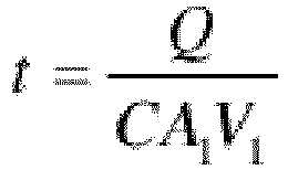
- Preferably, a calculation formula for predicting the oil filling time in step 1.4 is as follows:

- Preferably, a calculation formula for predicting the distance in step 1.5 is as follows:

- The present invention provides a control system, including a road ahead information acquisition module, a braking controller, and a hydraulic retarder;
- the road ahead information acquisition module is configured to acquire information of a road ahead of a vehicle and send the information of the road ahead to the braking controller, the information of the road ahead including a slope of a downhill road segment ahead of the vehicle and a distance between the vehicle and an origin of the downhill road segment ahead;
- the braking controller receives the information from the road ahead information acquisition module for implementing the control method for the hydraulic retarder according to any one of claims 1 to 8; and
- the hydraulic retarder is controlled by the braking controller to perform corresponding actions, the actions including starting oil filling, ending oil filling, starting braking or ending braking.
- Preferably, the road ahead information acquisition module is implemented through an electronic horizon.
- Compared with the prior art, the present invention has the following beneficial effects:
The control method for the hydraulic retarder and the control system according to the present invention are suitable for a cruising state with a steady vehicle speed, perform prediction and advanced control based on the information of the road ahead, and start the hydraulic retarder at the proper time, thus avoiding false triggering of an existing control method and alleviating the response lag of the hydraulic retarder. At the same time, by starting the hydraulic retarder for braking, the time for applying a brake for braking when the terrain changes may be shortened, thus lowering the wear of brake pads, reducing the waste of vehicle running costs, and having good economic efficiency. -
-
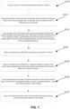
FIG. 1 is a schematic flow diagram of a method according to the present invention; and -
FIG. 2 is a schematic structural diagram of a system according to the present invention. - For clearer descriptions of the objectives, technical solutions, and advantages of the present invention, implementations of the present invention will be described hereinafter in detail with reference to the accompanying drawings.
- The execution subject of a method according to this embodiment is a braking controller of a vehicle, and an execution program and/or a database program of the method according to this embodiment may be installed to the braking controller of the vehicle, which is not specifically limited by the present invention.
- It is to be noted that step identifiers involved in the claims and description of the present application are merely to make the document clearer, and during specific implementations, the order of the steps may be adjusted accordingly according to requirements.
- Embodiment 1: As shown in
FIG. 1 , a control method for a hydraulic retarder includes: - S101: Acquire a slope of a downhill road segment ahead of a vehicle.
- S102: Determine whether an absolute value of the slope of the downhill road segment ahead of the vehicle is greater than an absolute value of a slope for which a braking force is not required.
- S103: If the absolute value of the slope of the downhill road segment ahead of the vehicle is greater than the absolute value of the slope for which the braking force is not required, predict a required braking force for the vehicle to travel, at a steady speed, on the downhill road segment ahead, and an oil amount required for the required braking force.
- S104: Predict corresponding oil filling time according to the required oil amount.
- S105: Predict, according to the oil filling time, a distance between a position of the vehicle and an origin of the downhill road segment ahead at the start time of oil filling of the hydraulic retarder.
- S106: In the case that the actual distance between the position of the vehicle and the origin of the downhill road segment ahead is equal to a predicted distance, control the hydraulic retarder to start oil filling.
- S107: Upon the vehicle reaching the origin of the downhill road segment ahead, control the hydraulic retarder to start braking.
- After step S107, the method further includes: when the vehicle ends traveling on the downhill road segment, end braking by the hydraulic retarder. Alternatively, after step S107, the method further includes: while the vehicle travels downhill, if it is detected that the slope of the downhill road segment changes and the absolute value of the slope of the downhill road segment is smaller than the absolute value of the slope for which the braking force is not required, end braking by the hydraulic retarder.
- In this embodiment, in calculation of the slope in step S102, a calculation formula of the slope for which the braking force is not required is as follows:

- Specifically, according to the force stationary equation of vehicle dynamics, a current resultant force applied to the vehicle is equal to the difference between a forward force provided by an engine and the external resistance to the vehicle. A calculation formula of the current resultant force applied to the vehicle is as follows:

- Further, the external resistance to the vehicle may be obtained respectively by the following calculation formulas:


- Since the vehicle is in the cruising state, the acceleration α of the vehicle is 0, and Fα and Facc are equal to 0.
- When θ=θmin , the braking force is not required, in this case, the engine output is 0, which may just maintain a current cruising speed, such that F is also equal to 0.
- Thus, the above formula Fa = F - Frol - Fslope - Facc - Fwin may be converted to:



- In one embodiment, in prediction of the braking force and the oil amount in step S103 (a monitoring method), predicting the required braking force for the vehicle to travel, at the steady speed, on the slope of the downhill road segment ahead, and the oil amount required for the braking force specifically includes:
Predict the required braking force Tr for the vehicle to travel, at the steady speed, on the slope of the downhill road segment ahead as follows:
- Acquire the oil amount Q required for the braking force as follows:

- In another embodiment, in prediction of the braking force and the oil amount in step S103 (a calibration method), predicting the required braking force for the vehicle to travel, at the steady speed, on the slope of the downhill road segment ahead, and the oil amount required for the braking force may further include:
Calibrate required braking forces for the vehicle to travel, at different speeds, on the slope of the downhill road segment ahead, and corresponding oil amounts. - Acquire a current traveling speed of the vehicle, and acquire, based on the calibrated data, the required braking force Tr for the vehicle to travel on the slope of the downhill road section ahead, and the oil amount Q required for the braking force. The calibrated data include the calibrated speeds, required braking forces and corresponding oil amounts.
- The calibrated speeds, required braking forces and corresponding oil amounts are stored in the form of a data table, a MAP graph, or a curve.
- Specifically, a series of different braking torques Tr to be achieved at different speeds V, and required oil amounts Q respectively may be pre-calibrated through the calibration method. Then, in this step, the required oil amount Q may be queried from the calibrated data based on Tr and the speeds V.
- For example, when V=50km/h, the corresponding relationship between the braking force Tr and the oil amount Q is shown in Table 1 below (Nmax denotes the maximum braking force at the speed, and Qmax denotes the maximum oil filling amount at the speed):
Table 1 Tr (N) Q(L) 1 0.7 1.5 1.3 2 2.2 ······ ······ Nmax Qmax - In addition, calibration tables for a plurality of speeds may be integrated to generate a three-dimensional calibration MAP with three axes: Tr, V and Q. In the three-dimensional calibration MAP, a value Q is found from values of the V and Tr axes.
- For prediction of the oil filling time in step S104, predicting the corresponding oil filling time according to the required oil amount is as follows:

- For prediction of the distance in step S105, predicting, according to the oil filling time, the distance between the position of the vehicle and the origin of the downhill road segment ahead at the start time of oil filling of the hydraulic retarder is as follows:

- In this embodiment, when the braking controller determines that the vehicle reaches a position Offset away from the downhill position, cruising at a steady speed is kept, and the hydraulic retarder starts oil filling. In this way, when the vehicle reaches the downhill position, the engine may not output torque, the hydraulic retarder plays the braking role, and the vehicle may keep the original cruising speed to travel at a constant speed on the condition that the engine does not output force. Thus, oil consumption is reduced, the wear on brake pads is avoided, and good economic efficiency is achieved.
- Embodiment 2: As shown in
FIG. 2 , a control system for a hydraulic retarder includes a road aheadinformation acquisition module 201, abraking controller 202, and thehydraulic retarder 203. - The road ahead
information acquisition module 201 is configured to acquire information of a road ahead of a vehicle and send the information of the road ahead to thebraking controller 202. The information of the road ahead includes a slope of a downhill road segment ahead of the vehicle and a distance between a current position of the vehicle and an origin of the downhill road segment ahead. - The
braking controller 202 receives the information from the road aheadinformation acquisition module 201 for implementing the control method for the hydraulic retarder in Embodiment 1. - The
hydraulic retarder 203 is controlled by thebraking controller 202 to perform corresponding actions. The actions include starting oil filling, ending oil filling, starting braking, or ending braking. - The
braking controller 202 further includes a storage module configured to store calibrated speeds, required braking forces and corresponding oil amounts in the form of a data table, a MAP graph, or a curve. - In this embodiment, the road ahead
information acquisition module 201 may be an electronic horizon configured to acquire the information of the road ahead of the vehicle. Of course, the road ahead information acquisition module may also be implemented by other devices, as long as the function of the road ahead information acquisition module may be realized, which is not specifically limited by the present invention. - The above are only specific implementations of the present invention, but the design concept of the present invention is not limited thereto. Any non-substantial modification of the present invention based on this concept shall fall within the scope of protection of the present invention.
- The control method for the hydraulic retarder and the control system according to the present invention are suitable for a cruising state with a steady vehicle speed, perform prediction and advanced control based on the information of the road ahead, and start the hydraulic retarder at the proper time, thus avoiding false triggering of an existing control method and alleviating the response lag of the hydraulic retarder. At the same time, by starting the hydraulic retarder for braking, the time for applying a brake for braking when the terrain changes may be shortened, thus lowering the wear of brake pads, reducing the waste of vehicle running costs, and having good economic efficiency.
Claims (11)
- A control method for a hydraulic retarder, characterized by comprising:1.1 acquiring a slope of a downhill road segment ahead of a vehicle;1.2 determining whether an absolute value of the slope of the downhill road segment ahead of the vehicle is greater than an absolute value of a slope for which a braking force is not required;1.3 if the absolute value of the slope of the downhill road segment ahead of the vehicle is greater than the absolute value of the slope for which the braking force is not required, predicting a required braking force for the vehicle to travel, at a steady speed, on the downhill road segment ahead, and an oil amount required for the braking force;1.4 predicting corresponding oil filling time according to the required oil amount;1.5 predicting, according to the oil filling time, a distance between the vehicle and an origin of the downhill road segment ahead at the start time of oil filling of the hydraulic retarder;1.6 in the case that the actual distance between the vehicle and the origin of the downhill road segment ahead is equal to a predicted distance, controlling the hydraulic retarder to start oil filling; and1.7 upon the vehicle reaching the origin of the downhill road segment ahead, controlling the hydraulic retarder to start braking.
- The control method for a hydraulic retarder according to claim 1, characterized in that after step 1.7, the method further comprises:
when the vehicle ends traveling on the downhill road segment ahead, ending braking by the hydraulic retarder. - The control method for a hydraulic retarder according to claim 1, characterized in that a calculation formula of the slope for which the braking force is not required in step 1.2 is as follows:

- The control method for a hydraulic retarder according to claim 1 or 3, characterized in that step 1.3 specifically comprises:predicting the required braking force Tr for the vehicle to travel, at the steady speed, on the slope of the downhill road segment ahead according to the following calculation formula:
 wherein m denotes the mass of the vehicle and the load carried, g denotes the acceleration of gravity, θ denotes the slope of the downhill road segment ahead of the vehicle, and θmin denotes the slope for which the braking force is not required; andcalculating the oil amount Q required for the braking force according to the required braking force as follows:
 wherein v1 denotes a flow velocity of oil at an inlet of a rotor impeller of the hydraulic retarder; v3 denotes a flow velocity of the oil at the inlet of the rotor impeller; R1 denotes a radius of the oil inlet of the rotor impeller; R3 denotes a radius of an oil outlet of the rotor impeller; and ρ denotes an oil density.
 - The control method for a hydraulic retarder according to claim 1 or 3, characterized in that step 1.3 specifically comprises:calibrating required braking forces for the vehicle to travel, at different speeds, on the downhill road segment ahead, and corresponding oil amounts; andacquiring a current traveling speed of the vehicle, and acquiring, based on the calibrated data, the required braking force Tr for the vehicle to travel on the downhill road section ahead, and the oil amount Q required for the braking force, the calibrated data comprising the calibrated speeds, required braking forces and corresponding oil amounts.
- The control method for a hydraulic retarder according to claim 5, characterized in that the calibrated speeds, required braking forces and corresponding oil amounts are stored in the form of a data table, a graph, or a curve.
- The control method for a hydraulic retarder according to claim 4 or 6, characterized in that a calculation formula for predicting the oil filling time in step 1.4 is as follows:
- The control method for a hydraulic retarder according to claim 1 or 7, characterized in that a calculation formula for predicting the distance in step 1.5 is as follows:

- A control system, characterized by comprising a road ahead information acquisition module, a braking controller, and a hydraulic retarder;the road ahead information acquisition module is configured to acquire information of a road ahead of a vehicle and send the information of the road ahead to the braking controller, the information of the road ahead comprising a slope of a downhill road segment ahead of the vehicle and a distance between the vehicle and an origin of the downhill road segment ahead;the braking controller receives the information from the road ahead information acquisition module for implementing the control method for the hydraulic retarder according to any one of claims 1 to 8; andthe hydraulic retarder is controlled by the braking controller to perform corresponding actions, the actions comprising starting oil filling, ending oil filling, starting braking or ending braking.
- The control system according to claim 9, characterized in that the road ahead information acquisition module is implemented through an electronic horizon.
- The control system according to claim 9, characterized in that the braking controller further comprises a storage module configured to store pre-calibrated speeds, required braking forces and corresponding oil amounts in the form of a data table, a MAP graph or a curve.
Applications Claiming Priority (2)
| Application Number | Priority Date | Filing Date | Title |
|---|---|---|---|
| CN202010705074.0A CN113954798B (en) | 2020-07-21 | 2020-07-21 | Control method and control system of hydraulic retarder |
| PCT/CN2020/139955 WO2022016807A1 (en) | 2020-07-21 | 2020-12-28 | Control method for hydraulic retarder, and control system |
Publications (4)
| Publication Number | Publication Date |
|---|---|
| EP4186758A1 true EP4186758A1 (en) | 2023-05-31 |
| EP4186758A4 EP4186758A4 (en) | 2024-08-21 |
| EP4186758C0 EP4186758C0 (en) | 2025-11-12 |
| EP4186758B1 EP4186758B1 (en) | 2025-11-12 |
Family
ID=79459958
Family Applications (1)
| Application Number | Title | Priority Date | Filing Date |
|---|---|---|---|
| EP20946026.0A Active EP4186758B1 (en) | 2020-07-21 | 2020-12-28 | Control method for hydraulic retarder, and control system |
Country Status (4)
| Country | Link |
|---|---|
| US (1) | US12337806B2 (en) |
| EP (1) | EP4186758B1 (en) |
| CN (1) | CN113954798B (en) |
| WO (1) | WO2022016807A1 (en) |
Families Citing this family (2)
| Publication number | Priority date | Publication date | Assignee | Title |
|---|---|---|---|---|
| CN115214563B (en) * | 2022-07-04 | 2024-01-02 | 一汽解放汽车有限公司 | A retarder control method, device, electronic equipment and storage medium |
| CN119239531B (en) * | 2024-11-04 | 2025-10-28 | 一汽解放汽车有限公司 | On-off type hydraulic retarder control method and device and computer equipment |
Family Cites Families (18)
| Publication number | Priority date | Publication date | Assignee | Title |
|---|---|---|---|---|
| JP3743692B2 (en) * | 1997-03-26 | 2006-02-08 | 株式会社小松製作所 | Retarder automatic control device |
| DE19833891A1 (en) * | 1998-07-28 | 2000-02-03 | Zahnradfabrik Friedrichshafen | Hydrodynamic retarder for motor vehicle has control system with regulating valve to deliver contents of pressurized accumulator to retarder, and which controls both emptying and replenishment of accumulator |
| US8401753B2 (en) | 2009-11-23 | 2013-03-19 | Caterpillar Inc. | Automatic downhill speed control system |
| DE102012004985A1 (en) * | 2012-03-14 | 2013-09-19 | Voith Patent Gmbh | Method for adjusting the braking torque of a hydrodynamic retarder |
| US8924119B2 (en) * | 2013-03-08 | 2014-12-30 | Caterpillar Inc. | Retarding downshift management |
| DE102013009535A1 (en) * | 2013-06-07 | 2014-12-11 | Voith Patent Gmbh | Method for controlling a hydrodynamic retarder which can be decoupled via a separating clutch |
| JP6424229B2 (en) * | 2014-01-28 | 2018-11-14 | ボルボトラックコーポレーション | Vehicle driver feedback system, vehicle equipped with the system, method for providing vehicle driver feedback, computer program, computer readable medium and control device |
| CN104773151B (en) | 2015-03-17 | 2017-07-28 | 吉林大学 | The fill ratio automatic obtaining method and device of Retarder |
| CN104908728B (en) | 2015-06-12 | 2019-01-22 | 宁波华盛汽车部件有限公司 | Control system and control method of hydraulic retarder |
| CN105480217A (en) * | 2015-11-30 | 2016-04-13 | 宁波华盛汽车部件有限公司 | Control system and control method for hydraulic retarder of vehicle |
| CN105752062A (en) | 2016-05-18 | 2016-07-13 | 苏州特速安机电科技有限公司 | Servo control system for hydraulic retarder |
| CN106994966A (en) | 2017-01-05 | 2017-08-01 | 宁波华盛联合制动科技有限公司 | A kind of Retarder control device and method |
| WO2018197586A1 (en) * | 2017-04-26 | 2018-11-01 | Dana Belgium N.V. | Hydrodynamic retarder system and method of controlling a hydrodynamic retarder system |
| US10948064B2 (en) * | 2017-06-09 | 2021-03-16 | Volvo Truck Corporation | Method for controlling a differential braking arrangement |
| KR102383233B1 (en) * | 2017-09-07 | 2022-04-05 | 현대자동차 주식회사 | Oil drain protecting device for continuously variable valve timing apparatus |
| CN107738579B (en) * | 2017-11-14 | 2024-05-07 | 长安大学 | A safety control method for heavy trucks going down a long slope |
| SE542825C2 (en) | 2018-04-26 | 2020-07-14 | Scania Cv Ab | A method for controlling a motor vehicle |
| US11427168B2 (en) * | 2020-01-13 | 2022-08-30 | Caterpillar Sarl | Brake system for a vehicle |
-
2020
- 2020-07-21 CN CN202010705074.0A patent/CN113954798B/en active Active
- 2020-12-28 WO PCT/CN2020/139955 patent/WO2022016807A1/en not_active Ceased
- 2020-12-28 US US18/006,419 patent/US12337806B2/en active Active
- 2020-12-28 EP EP20946026.0A patent/EP4186758B1/en active Active
Also Published As
| Publication number | Publication date |
|---|---|
| CN113954798A (en) | 2022-01-21 |
| EP4186758A4 (en) | 2024-08-21 |
| WO2022016807A1 (en) | 2022-01-27 |
| US20230347856A1 (en) | 2023-11-02 |
| CN113954798B (en) | 2025-11-28 |
| EP4186758C0 (en) | 2025-11-12 |
| EP4186758B1 (en) | 2025-11-12 |
| US12337806B2 (en) | 2025-06-24 |
Similar Documents
| Publication | Publication Date | Title |
|---|---|---|
| US10328915B2 (en) | Vehicle stability control system and method | |
| EP2507104B1 (en) | Method and system for controlling a vehicle cruise control | |
| CN112622872B (en) | A kind of energy recovery control method and device | |
| JP5207953B2 (en) | Auto cruise control device for hybrid vehicle and automatic braking control device for vehicle | |
| US20120089313A1 (en) | System and method for reducing brake fade | |
| JP2018509706A (en) | How to control the distance between cars | |
| EP4186758B1 (en) | Control method for hydraulic retarder, and control system | |
| CN103223936A (en) | Auxiliary electricity and liquid composite braking control method applied for hybrid vehicle to go downhill | |
| CN109017441B (en) | New energy automobile self-adaptive ramp control method | |
| CN101578209A (en) | A method for controlling cooling of an auxiliary brake | |
| KR20190003096A (en) | Vehicle having electric motor and method of controlling coasting torque for the same | |
| CN117341692A (en) | A vehicle cruise control method, cruise control device, equipment and storage medium | |
| JP6855178B2 (en) | A method for driving a vehicle-specific braking system with an electric motor, and a control device for at least one electric motor of the vehicle-specific braking system. | |
| CN115675460A (en) | Control method, device and equipment of cruise brake system and storage medium | |
| JP5237599B2 (en) | vehicle | |
| US11345345B2 (en) | Method for operating a motor vehicle, and corresponding motor vehicle | |
| US11660967B2 (en) | Closed-loop control of regenerative braking | |
| TW201819222A (en) | Energy-conservation vehicle driving control system | |
| CN114590251A (en) | Safe and energy-saving driving auxiliary device and auxiliary driving method for new energy automobile | |
| CN115649168A (en) | Vehicle stabilization control method, device, equipment and storage medium | |
| JP7279279B2 (en) | Braking control device | |
| CN119319831B (en) | Method and device for controlling vehicle braking system, vehicle and storage medium | |
| CN118991757A (en) | Vehicle self-adaptive cruise control method and device based on exhaust brake | |
| CN120792801A (en) | Drivability control method for automatic parking vehicle | |
| CN120422858A (en) | Vehicle control method and device, vehicle and storage medium |
Legal Events
| Date | Code | Title | Description |
|---|---|---|---|
| STAA | Information on the status of an ep patent application or granted ep patent |
Free format text: STATUS: THE INTERNATIONAL PUBLICATION HAS BEEN MADE |
|
| PUAI | Public reference made under article 153(3) epc to a published international application that has entered the european phase |
Free format text: ORIGINAL CODE: 0009012 |
|
| STAA | Information on the status of an ep patent application or granted ep patent |
Free format text: STATUS: REQUEST FOR EXAMINATION WAS MADE |
|
| 17P | Request for examination filed |
Effective date: 20230221 |
|
| AK | Designated contracting states |
Kind code of ref document: A1 Designated state(s): AL AT BE BG CH CY CZ DE DK EE ES FI FR GB GR HR HU IE IS IT LI LT LU LV MC MK MT NL NO PL PT RO RS SE SI SK SM TR |
|
| DAV | Request for validation of the european patent (deleted) | ||
| DAX | Request for extension of the european patent (deleted) | ||
| A4 | Supplementary search report drawn up and despatched |
Effective date: 20240723 |
|
| RIC1 | Information provided on ipc code assigned before grant |
Ipc: F16D 57/00 20060101ALI20240718BHEP Ipc: B60T 10/00 20060101AFI20240718BHEP |
|
| RAP3 | Party data changed (applicant data changed or rights of an application transferred) |
Owner name: XIAMEN YAXON ZHILIAN TECHNOLOGY CO., LTD. |
|
| GRAP | Despatch of communication of intention to grant a patent |
Free format text: ORIGINAL CODE: EPIDOSNIGR1 |
|
| STAA | Information on the status of an ep patent application or granted ep patent |
Free format text: STATUS: GRANT OF PATENT IS INTENDED |
|
| INTG | Intention to grant announced |
Effective date: 20250530 |
|
| GRAS | Grant fee paid |
Free format text: ORIGINAL CODE: EPIDOSNIGR3 |
|
| GRAA | (expected) grant |
Free format text: ORIGINAL CODE: 0009210 |
|
| STAA | Information on the status of an ep patent application or granted ep patent |
Free format text: STATUS: THE PATENT HAS BEEN GRANTED |
|
| AK | Designated contracting states |
Kind code of ref document: B1 Designated state(s): AL AT BE BG CH CY CZ DE DK EE ES FI FR GB GR HR HU IE IS IT LI LT LU LV MC MK MT NL NO PL PT RO RS SE SI SK SM TR |
|
| REG | Reference to a national code |
Ref country code: CH Ref legal event code: F10 Free format text: ST27 STATUS EVENT CODE: U-0-0-F10-F00 (AS PROVIDED BY THE NATIONAL OFFICE) Effective date: 20251112 Ref country code: GB Ref legal event code: FG4D |
|
| REG | Reference to a national code |
Ref country code: IE Ref legal event code: FG4D |
|
| REG | Reference to a national code |
Ref country code: DE Ref legal event code: R096 Ref document number: 602020062281 Country of ref document: DE |
|
| U01 | Request for unitary effect filed |
Effective date: 20251212 |
|
| U07 | Unitary effect registered |
Designated state(s): AT BE BG DE DK EE FI FR IT LT LU LV MT NL PT RO SE SI Effective date: 20260122 |
|
| PGFP | Annual fee paid to national office [announced via postgrant information from national office to epo] |
Ref country code: GB Payment date: 20260331 Year of fee payment: 6 |
|
| PG25 | Lapsed in a contracting state [announced via postgrant information from national office to epo] |
Ref country code: ES Free format text: LAPSE BECAUSE OF FAILURE TO SUBMIT A TRANSLATION OF THE DESCRIPTION OR TO PAY THE FEE WITHIN THE PRESCRIBED TIME-LIMIT Effective date: 20251112 |
|
| PG25 | Lapsed in a contracting state [announced via postgrant information from national office to epo] |
Ref country code: NO Free format text: LAPSE BECAUSE OF FAILURE TO SUBMIT A TRANSLATION OF THE DESCRIPTION OR TO PAY THE FEE WITHIN THE PRESCRIBED TIME-LIMIT Effective date: 20260212 |
|
| PG25 | Lapsed in a contracting state [announced via postgrant information from national office to epo] |
Ref country code: HR Free format text: LAPSE BECAUSE OF FAILURE TO SUBMIT A TRANSLATION OF THE DESCRIPTION OR TO PAY THE FEE WITHIN THE PRESCRIBED TIME-LIMIT Effective date: 20251112 |
|
| PG25 | Lapsed in a contracting state [announced via postgrant information from national office to epo] |
Ref country code: RS Free format text: LAPSE BECAUSE OF FAILURE TO SUBMIT A TRANSLATION OF THE DESCRIPTION OR TO PAY THE FEE WITHIN THE PRESCRIBED TIME-LIMIT Effective date: 20260212 |
|
| PG25 | Lapsed in a contracting state [announced via postgrant information from national office to epo] |
Ref country code: IS Free format text: LAPSE BECAUSE OF FAILURE TO SUBMIT A TRANSLATION OF THE DESCRIPTION OR TO PAY THE FEE WITHIN THE PRESCRIBED TIME-LIMIT Effective date: 20260312 |
|
| PG25 | Lapsed in a contracting state [announced via postgrant information from national office to epo] |
Ref country code: PL Free format text: LAPSE BECAUSE OF FAILURE TO SUBMIT A TRANSLATION OF THE DESCRIPTION OR TO PAY THE FEE WITHIN THE PRESCRIBED TIME-LIMIT Effective date: 20251112 |