EP4186748A1 - International standards organization fix (isofix) mechanism and safety seat comprising same - Google Patents
International standards organization fix (isofix) mechanism and safety seat comprising same Download PDFInfo
- Publication number
- EP4186748A1 EP4186748A1 EP22189207.8A EP22189207A EP4186748A1 EP 4186748 A1 EP4186748 A1 EP 4186748A1 EP 22189207 A EP22189207 A EP 22189207A EP 4186748 A1 EP4186748 A1 EP 4186748A1
- Authority
- EP
- European Patent Office
- Prior art keywords
- locking member
- locking
- fastening member
- sleeve
- limiting
- Prior art date
- Legal status (The legal status is an assumption and is not a legal conclusion. Google has not performed a legal analysis and makes no representation as to the accuracy of the status listed.)
- Pending
Links
- 230000007246 mechanism Effects 0.000 title claims abstract description 60
- 230000008520 organization Effects 0.000 title description 2
- 238000000034 method Methods 0.000 description 6
- 230000008569 process Effects 0.000 description 6
- 238000010586 diagram Methods 0.000 description 5
- 230000009471 action Effects 0.000 description 4
- 238000003780 insertion Methods 0.000 description 3
- 230000037431 insertion Effects 0.000 description 3
- 230000009286 beneficial effect Effects 0.000 description 1
- 238000004891 communication Methods 0.000 description 1
- 230000007423 decrease Effects 0.000 description 1
- 230000004069 differentiation Effects 0.000 description 1
- 230000010354 integration Effects 0.000 description 1
- 230000002452 interceptive effect Effects 0.000 description 1
- 238000012986 modification Methods 0.000 description 1
- 230000004048 modification Effects 0.000 description 1
Images


Classifications
-
- B—PERFORMING OPERATIONS; TRANSPORTING
- B60—VEHICLES IN GENERAL
- B60N—SEATS SPECIALLY ADAPTED FOR VEHICLES; VEHICLE PASSENGER ACCOMMODATION NOT OTHERWISE PROVIDED FOR
- B60N2/00—Seats specially adapted for vehicles; Arrangement or mounting of seats in vehicles
- B60N2/24—Seats specially adapted for vehicles; Arrangement or mounting of seats in vehicles for particular purposes or particular vehicles
- B60N2/26—Seats specially adapted for vehicles; Arrangement or mounting of seats in vehicles for particular purposes or particular vehicles for children
- B60N2/28—Seats readily mountable on, and dismountable from, existing seats or other parts of the vehicle
- B60N2/2887—Fixation to a transversal anchorage bar, e.g. isofix
Definitions
- the present invention relates to the technical field of safety seats, and particularly to an International Standards Organization FIX (ISOFIX) mechanism and a safety seat including the same.
- ISOFIX International Standards Organization FIX
- ISOFIX refers to a connection structure between a child restraint system and a vehicle.
- the locking member in the ISOFIX mechanism is used to lock the shell relative to the sleeve.
- a spring is adopted to act on the locking member to maintain the locking of the shell relative to the sleeve, the locking member will be unlocked when being squeezed or collided by an external force, and consequently the shell can slide relative to the sleeve, leading to a technical problem that the length dimension of the ISOFIX mechanism cannot be locked.
- An objective of the present invention is to provide an ISOFIX mechanism and a safety seat including the same, to alleviate the technical problem in the prior art that the length dimension of the ISOFIX mechanism cannot be locked when the ISOFIX mechanism is squeezed or collided.
- the present invention provides an ISOFIX mechanism, including a sleeve, a shell, a fastening member, a connecting rod, and a locking member.
- the shell is slidably connected in the sleeve.
- the connecting rod includes a first pushing portion and a limiting portion.
- the fastening member, the connecting rod, and the locking member are each movably connected in the shell.
- the fastening member In an unlocked state, the fastening member is in a non-engaging state, the locking member is locked on the sleeve, the first pushing portion abuts against the fastening member, and the limiting portion abuts against the locking member to prevent the locking member from detaching from the sleeve.
- the connecting rod further includes a second abutting portion, and when an external force acts on the connecting rod in a lock releasing direction, the ISOFIX mechanism switches from the unlocked state to a lock released state, the limiting portion gives a way to the locking member, and the second abutting portion abuts against the locking member and causes the locking member to be unlocked relative to the sleeve.
- a release operating member is mounted on the connecting rod, and the release operating member passes through the shell and the sleeve to extend to an outside of the sleeve, the sleeve and/or the shell are/is provided with a sliding groove, and the release operating member is slidably engaged in the sliding groove.
- a first elastic device is mounted on the shell, and the first elastic device is connected to the locking member, and the first elastic device has a tendency to lock the locking member to the sleeve.
- a second elastic device is mounted in the shell, the second elastic device is connected to the fastening member, and the second elastic device has a tendency of causing the fastening member to switch from an engaging state to the non-engaging state.
- the second elastic device is connected between the fastening member and the connecting rod, and the second elastic device has a tendency to cause the connecting rod to move opposite to a lock releasing direction and causes the connecting rod to abut against the fastening member to abut or lock the fastening member.
- the fastening member is rotatably connected in the shell, and the fastening member includes a first contact surface
- the first pushing portion abuts against the arc surface.
- an end surface of the limiting portion facing toward the locking member is inclined in a direction avoiding the locking member.
- the sleeve is provided with a plurality of locking slots, and the plurality of locking slots are arranged at intervals, and the locking member is provided with a locking protrusion matching with each of the locking slots.
- the locking member further includes a first protruding portion; in the unlocked state, the limiting portion abuts against the first protruding portion; and in a lock released state or a locked state, the limiting portion is staggered from the first protruding portion.
- the locking member is provided with a clearance groove, and the clearance groove is located on a side of the first protruding portion away from the fastening member; from the unlocked state to the locked state, the limiting portion moves relative to the first protruding portion toward a direction away from the clearance groove; and from the unlocked state to the lock released state, the limiting portion moves relative to the first protruding portion toward an inside of the clearance groove.
- the locking member further includes a second protruding portion; and from the unlocked state to the lock released state, the connecting rod abuts against the second protruding portion, and causes the locking protrusion to detach from each of the locking slots.
- a shaft rod is mounted on the shell, the locking member is rotatably connected to the shaft rod, the first protruding portion and the second protruding portion are arranged at intervals around the shaft rod, and the clearance groove is formed between the first protruding portion and the second protruding portion.
- a limiting member is mounted on the shell, the locking member is provided with a limiting groove, and the limiting member is located in the limiting groove.
- the locking member further includes an eccentric protrusion, the second protruding portion is spaced apart from the eccentric protrusion, and the limiting groove is formed between the second protruding portion and the eccentric protrusion;
- the present invention provides a safety seat, including the ISOFIX mechanism according to the first aspect.
- the embodiments of the present invention have the following beneficial effects.
- the shell is slidably connected in the sleeve.
- the connecting rod includes the first pushing portion and the limiting portion.
- the fastening member, the connecting rod, and the locking member are each movably connected in the shell.
- the fastening member In the unlocked state, the fastening member is in the non-engaging state, the locking member is locked on the sleeve, the first pushing portion abuts against the fastening member, and the limiting portion abuts against the locking member to prevent the locking member from detaching from the sleeve.
- the limiting portion can prevent the locking member from getting loosened relative to the sleeve, so that the shell remains locked relative to the sleeve, thereby avoiding the technical problem that the length dimension of the ISOFIX mechanism cannot be locked when the locking member is squeezed or collided.
- orientation or positional relationships indicated by the terms “center”, “upper”, “lower”, “left”, “right”, “vertical”, “horizontal”, “inner”, “outer”, etc. are based on the orientation or positional relationships shown in the drawings, and are only for the convenience of describing the present invention and simplifying the description, rather than indicating or implying that the apparatus or element described must have a specific orientation or be constructed and operated in a specific orientation, and therefore are not to be construed as limiting the present invention.
- first and “second” are used herein for purposes of description, and are not intended to indicate or imply relative importance.
- a physical quantity in a formula if not marked separately, should be understood as a basic quantity of a basic unit of the International System of Units, or a derived quantity derived from the basic quantity through mathematical operations such as multiplication, division, differentiation, or integration.
- the terms "mount”, “connect”, “couple”, and variants thereof should be interpreted in a broad sense, for example, may be a fixed connection, a detachable connection, or an integral connection; may be a mechanical connection or an electrical connection; or may be a direct connection, an indirectly connection via an intermediate medium, or communication between the interiors of two components.
- the specific meanings of the above terms in the present invention can be understood according to specific circumstances.
- this embodiment of the present invention provides an ISOFIX mechanism, including a sleeve 001, a shell 002, a fastening member 003, a connecting rod 004, and a locking member 005.
- the shell 002 is slidably connected in the sleeve 001.
- the connecting rod 004 includes a first pushing portion 401 and a limiting portion 402, and the fastening member 003, the connecting rod 004, and the locking member 005 are each movably connected in the shell 002.
- the fastening member 003 are in a non-engaging state, the locking member 005 is locked on the sleeve 001, the first pushing portion 401 abuts against the fastening member 003, and the limiting portion 402 abuts against the locking member 005 to prevent the locking member 005 from detaching from the sleeve 001.
- the position of the connecting rod 004 can be kept stable, that is, the connecting rod 004 cannot move toward the right side in FIG. 1 , so as to prevent the limiting portion 402 from deviating relative to the locking member 005. Therefore, the limiting portion 402 remains in the state of abutting against the locking member 005.
- the pushing action of the limiting portion 402 prevents the locking member 005 from detaching from the sleeve 001, which can ensure that the locking member 005 is always locked on the sleeve 001 to limit the sliding of the shell 002 along the sleeve 001, providing a function of locking the length dimension of the ISOFIX mechanism.
- the locking member 005 in the unlocked state, is limited by the limiting portion 402, which can prevent the locking member 005 from detaching from the sleeve 001 due to squeezing or collision, thereby fixing the shell 002 relative to the sleeve 001.
- the length dimension of the ISOFIX mechanism is locked, and the ISOFIX mechanism can be connected to an anchor point on a vehicle by pushing and pressing. After the ISOFIX mechanism is connected to the anchor point on the vehicle, the fastening member 003 is switched to the engaging state.
- the connecting rod 004 further includes a second abutting portion 403.
- the ISOFIX mechanism switches from the unlocked state to a lock released state
- the limiting portion 402 gives a way to the locking member 005
- the second abutting portion 403 abuts against the locking member 005 and causes the locking member 005 to be unlocked relative to the sleeve 001.
- the fastening member 003 is always kept in the non-engaging state.
- a release operating member 404 is mounted on the connecting rod 004, and the release operating member 404 passes through the shell 002 and the sleeve 001 to extend to an outside of the sleeve 001, the sleeve 001 and/or the shell 002 are/is provided with a sliding groove, and the release operating member 404 is slidably engaged in the sliding groove.
- one of the sleeve 001 and the shell 002 is provided with a sliding groove, and the other is provided with a groove opening, and the sliding groove is opposite to the groove opening.
- the release operating member 404 extends to the outside of the sleeve 001 through the sliding groove and the groove opening, and the release operating member 404 is slidable along the sliding groove. An operator may touch the release operating member 404 outside the sleeve 001, and operate the release operating member 404 to slide in the x-direction in FIG. 1 .
- the sleeve 001 and the shell 002 are respectively provided with two sliding grooves, the two sliding grooves are arranged opposite to each other, the release operating member 404 extends to the outside of the sleeve 001 through the two sliding grooves, and the release operating member 404 is slidable along the sliding grooves.
- the release operating member 404 When the release operating member 404 is manually operated to slide toward the left side in FIG. 1 , the second abutting portion 403 pushes against the locking member 005 and causes the locking member 005 to be unlocked relative to the sleeve 001, and the connecting rod 004 pulls the fastening member 003 through the second elastic device 008, so that the fastening member 003 can be switched to the non-engaging state.
- the ISOFIX mechanism is switched to a locked state.
- the locking member 005 is locked on the sleeve 001
- the limiting portion 402 gives a way to the locking member 005, so that the locking member 005 is no longer locked.
- the fastening member 003 is switched to the engaging state, and the first pushing portion 401 is inserted into a locking portion of the fastening member 003, so that the fastening member 003 is locked in the engaging state.
- a first elastic device 007 is mounted on the shell 002, and the first elastic device 007 is connected to the locking member 005.
- the first elastic device 007 has a tendency to lock the locking member 005 to the sleeve 001.
- the locking member 005 is slidably connected to the shell 002, to achieve insertion/removal of the locking protrusion 510 into/from a locking slot 101.
- a shaft rod 006 is mounted on the shell 002, and the locking member 005 is rotatably connected to the shaft rod 006.
- the locking member 005 is provided with a shaft hole 540, and the shaft rod 006 is inserted into the shaft hole 540, so that the locking member 005 can rotate about the shaft rod 006, to achieve insertion/removal of the locking protrusion 510 into/from the locking slot 101.
- the first elastic device 007 includes a tension spring or a torsion spring
- the locking member 005 is provided with a limiting hole 551
- an end of the first elastic device 007 is inserted into the limiting hole 551
- an elastic force of the first elastic device 007 acts on the locking member 005, so that the locking protrusion 510 of the locking member 005 remains in a state of being inserted in the locking slot 101.
- the second abutting portion 403 is arranged on an end of the connecting rod 004 away from the first pushing portion 401.
- the locking member 005 overcomes the elastic force of the first elastic device 007 and rotates about the shaft rod 006, so that the locking protrusion 510 can be pulled out from the locking slot 101.
- a second elastic device 008 is mounted in the shell 002, the second elastic device 008 is connected to the fastening member 003, and the second elastic device 008 has a tendency of causing the fastening member 003 to switch from an engaging state to the non-engaging state.
- the second elastic device 008 includes a tension spring or a torsion spring, an end of the second elastic device 008 is connected to the fastening member 003, and an elastic force of the second elastic device 008 acts on the fastening member 003, so that the fastening member 003 can be kept in the non-engaging state.
- the fastening member 003 is provided with a hooking groove 303.
- a locking pin is pushed against the fastening member 003 and is inserted into the hooking groove 303, to push the fastening member 003 to switch from the non-engaging state to the engaging state, so that the locking pin can be limited in the hooking groove 303.
- the fastening member 003 is provided with a mounting hole 304, a pin shaft is mounted on the shell 002, and the mounting hole 304 is sleeved on the pin shaft, so that the fastening member 003 can rotate about the pin shaft.
- a locking pin of the anchor point on the vehicle is pushed against the fastening member 003, so that the fastening member 003 rotates around the pin shaft, to cause the locking pin to be limited in the hooking groove 303, thereby achieving the switching of the fastening member 003 from the non-engaging state to the engaging state.
- the second elastic device 008 is connected between the fastening member 003 and the connecting rod 004, and the second elastic device 008 has a tendency to cause the connecting rod 004 to move opposite to the lock releasing direction x and causes the connecting rod 004 to abut against the fastening member 003 to abut or lock the fastening member 003.
- the second elastic device 008 has an elastic force that pulls the fastening member 003 and the connecting rod 004 to move toward each other.
- the fastening member 003 not only tends to maintain the non-engaging state, but also can elastically pull the connecting rod 004 to move opposite to the lock releasing direction x.
- the first pushing portion 401 abuts against the fastening member 003, and the fastening member 003 can prevent the connecting rod 004 from moving opposite to the lock releasing direction x, i.e., from moving toward the right side of FIG. 1 .
- the first pushing portion 401 is inserted into the locking portion of the fastening member 003, to lock the fastening member 003 in the engaging state.
- the sleeve 001 is provided with a plurality of locking slots 101, and the plurality of locking slots 101 are arranged at intervals along an extending direction of the sleeve 001.
- the locking member 005 is provided with a locking protrusion 510 matching with each of the locking slots 101.
- the locking member 005 When the locking protrusion 510 is inserted in a locking slot 101 of the locking slots 101, the locking member 005 is locked on the sleeve 001, so that the shell 002 can be fixed relative to the sleeve 001, thereby locking the length dimension of the ISOFIX mechanism.
- the shell 002 When the locking protrusion 510 is detached from the locking slot 101, the shell 002 can slide relative to the sleeve 001, and the shell 002 can be extended or retracted relative to the sleeve 001, so that the length dimension of the ISOFIX mechanism can be adjusted.
- the locking member 005 further includes a first protruding portion 520.
- the limiting portion 402 In the unlocked state, the limiting portion 402 abuts against the first protruding portion 520, thereby completely locking the locking member 005.
- the limiting portion 402 In a lock released state or a locked state, the limiting portion 402 is staggered from the first protruding portion 520.
- the locked state the locking protrusion 510 is inserted in the locking slot 101, but the limiting portion 402 is staggered from the first protruding portion 520, and the locking member 005 is not locked by the limiting portion 402, so that the locking member 005 is semi-locked.
- the second abutting portion 403 pushes against the locking member 005 and causes the locking protrusion 510 to be pulled out from the locking slot 101.
- the limiting portion 402 is staggered from the first protruding portion 520, so that the locking member 005 can be unlocked relative to the sleeve 001.
- the locking member 005 is provided with a clearance groove 501, and the clearance groove 501 is located on a side of the first protruding portion 520 away from the fastening member 003. From the unlocked state to the locked state, the limiting portion 402 moves relative to the first protruding portion 520 toward a direction away from the clearance groove 501. From the unlocked state to the lock released state, the limiting portion 402 moves relative to the first protruding portion 520 toward an inside of the clearance groove 501.
- the locking member 005 further includes a second protruding portion 530. From the unlocked state to the lock released state, the connecting rod 004 abuts against the second protruding portion 530, and causes the locking protrusion 510 to detach from each of the locking slots 101.
- a shaft rod 006 is mounted on the shell 002, the locking member 005 is rotatably connected to the shaft rod 006, the first protruding portion 520 and the second protruding portion 530 are arranged at intervals around the shaft rod 006, and the clearance groove 501 is formed between the first protruding portion 520 and the second protruding portion 530.
- the locking member 005 is provided with a shaft hole 540, and the shaft rod 006 is inserted into the shaft hole 540, so that the locking member 005 can rotate about the shaft rod 006, to achieve insertion/removal of the locking protrusion 510 into/from the locking slot 101.
- the locking protrusion 510, the second protruding portion 530, and the eccentric protrusion 550 are each arranged on the locking member 005, and the locking protrusion 510, the second protruding portion 530, and the eccentric protrusion 550 are arranged at intervals around the shaft hole 540.
- the first protruding portion 520 faces away from the locking protrusion 510, and the clearance groove 501 is located between the first protruding portion 520 and the second protruding portion 530.
- the fastening member 003 is rotatably connected in the shell 002, and the fastening member 003 includes a first contact surface 301.
- the first contact surface 301 includes an arc surface.
- the arc surface is coaxial with a rotating shaft of the fastening member 003, and the connecting rod 004 keeps its position unchanged during the fastening member 003 switching from the engaging state to the non-engaging state.
- the locking pin at the anchor point on the vehicle is pushed against the fastening member 003 to cause the fastening member 003 to swing.
- the elastic force of the second elastic device 008 causes the first pushing portion 401 to abut against the arc surface, so that the connecting rod 004 does not move along the lock releasing direction x, and the limiting portion 402 can keep abutting against the first protruding portion 520 of the locking member 005.
- an axis of the arc surface is spaced from an axis of the rotating shaft of the fastening member 003, so that during the fastening member 003 switching from the non-engaging state to the engaging state, the connecting rod 004 has a headroom to move opposite to the lock releasing direction.
- the first pushing portion 401 abuts against the arc surface.
- the second elastic device 008 pulls the connecting rod 004 to move opposite to the lock releasing direction x (toward the right side in FIG. 1 ), so that the first pushing portion 401 always abuts against the arc surface.
- the first elastic device 007 causes the locking member 005 to keep being locked to the sleeve 001, i.e., the locking member 005 is kept in the locked state by the elastic force of the first elastic device 007, thereby maintaining the state in which the locking protrusion 510 is inserted in the locking slot 101.
- an end surface of the limiting portion 402 facing toward the locking member 005 is inclined in a direction avoiding the locking member 005.
- an end surface of the limiting portion 402 facing toward the first protruding portion 520 is inclined in a direction away from the first protruding portion 520.
- the connecting rod 004 always abuts against the first contact surface 301.
- the connecting rod 004 moves opposite to the lock releasing direction x, i.e., toward the right side in FIG.
- the limiting portion 402 abuts against the first protruding portion 520, and the first protruding portion 520 can prevent the connecting rod 004 from moving along the lock releasing direction x.
- the fastening member 003 does not push the connecting rod 004 to move along the lock releasing direction x, thereby ensuring the smooth rotation of the fastening member 003.
- a limiting member 009 is mounted on the shell 002, the locking member 005 is provided with a limiting groove 502, and the limiting member 009 is located in the limiting groove 502.
- the limiting member 009 is limited in the limiting groove 502, so that the locking member 005 is limited during switching between working positions.
- the locking member 005 further includes an eccentric protrusion 550, the second protruding portion 530 is spaced apart from the eccentric protrusion 550, and the limiting groove 502 is formed between the second protruding portion 530 and the eccentric protrusion 550.
- the limiting member 009 abuts against the eccentric protrusion 550.
- the locking member 005 is unlocked relative to the sleeve 001, the limiting member 009 abuts against the second protruding portion 530.
- a gap is provided between the limiting member 009 and the end surface of the limiting groove 502 facing toward the limiting member 009, so that during rotation of the locking member 005 about the shaft rod 006, no friction occurs between the locking member 005 and the limiting member 009.
- the end surface of the limiting groove 502 facing toward the limiting member 009 is configured as an arc-shaped surface, and the arc-shaped surface is coaxial with the shaft rod 006.
- the limiting member 009 is rotatably connected to a limiting shaft rod on the shell 002. During the rotation of the locking member 005 about the shaft rod 006, the arc-shaped surface rubs the limiting shaft rod and causes the limiting shaft rod to rotate about its own axis, thereby reducing the frictional resistance received by the locking member 005.
- the eccentric protrusion 550 is provided with a limiting hole 551
- the first elastic device 007 is a tension spring, one end of the tension spring is connected to the shell 002, and the other end of the tension spring is connected into the limiting hole 551.
- the first elastic device 007 drives the locking member 005 to rotate about the shaft rod 006 and causes the locking protrusion 510 to tend to be inserted into the locking slot 101.
- the locking protrusion 510 has a first limiting end surface 511 and a second limiting end surface 512, and the first limiting end surface 511 is opposite to the second limiting end surface 512.
- the first limiting end surface 511 and the second limiting end surface 512 are both limited in the locking slot 101, so that the shell 002 cannot slide relative to the sleeve 001, thereby fixing the length dimension of the ISOFIX mechanism.
- the first limiting end surface 511 abuts against an inner wall surface of the locking slot 101, which can prevent the shell 002 from retracting toward inside of the sleeve 001, thereby preventing the length dimension of the ISOFIX mechanism from being shortened.
- the second limiting end surface 512 abuts against the inner wall surface of the locking slot 101, which can prevent the shell 002 from being stretched toward the outside of the sleeve 001, thereby fixing the length dimension of the ISOFIX mechanism.
- the fastening member 003 has a second contact surface 302, and the first contact surface 301 and the second contact surface 302 are arranged at intervals around a circumferential direction of the mounting hole 304.
- the first pushing portion 401 abuts against the first contact surface 301, to prevent the connecting rod 004 from moving toward the right side in FIG. 1 .
- the fastening member 003 rotates about an axis of the mounting hole 304 and causes the first pushing portion 401 to detach from the first contact surface 301, and then under a pulling force of the second elastic device 008, the connecting rod 004 slides toward the fastening member 003 and causes the first pushing portion 401 to abut against the second contact surface 302.
- the second contact surface 302 extends along a radial direction of the first contact surface 301.
- This embodiment of the present invention provides a safety seat, including the ISOFIX mechanism provided in the above implementations.
- the ISOFIX mechanism Before use, first, the ISOFIX mechanism is placed in a lock released position shown in FIG. 1 , and the limiting portion 402 abuts against the locking member 005, so that the locking member 005 is in a fully locked state, i.e., the locking member 005 is locked in the locking slot 101, and the locking member 005 can be prevented from detaching from the locking slot 101, thereby fixing the length dimension of the ISOFIX mechanism.
- the elastic force of the second elastic device acts on the fastening member 003, so that the fastening member 003 is kept in the non-engaging state.
- the ISOFIX mechanism When the safety seat is mounted on a vehicle, the ISOFIX mechanism is operated to connect to an anchor point on the vehicle, and the locking pin at the anchor point on the vehicle abuts against the fastening member 003, so as to push the fastening member 003 to switch from the non-engaging state to the engaging state.
- the second elastic device 008 pulls the connecting rod 004, to cause the first pushing portion 401 to abut against the second contact surface 302, so that the fastening member 003 can be limited in the engaging state.
- the locking member 005 is in a semi-locked state, and the elastic force of the first elastic device 007 acts on the locking member 005, so as to cause the locking protrusion 510 to be inserted into the locking slot 101.
- the connecting rod 004 is deviated in a direction away from the locking member 005, so that the limiting portion 402 is staggered from the first protruding portion 520. At this time, the connecting rod 004 no longer has the function of locking the locking member 005. Referring to FIG. 3 , FIG. 5 , and FIG.
- the fastening member 003 is kept in the non-engaging state under the elastic force of the second elastic device 008.
- the second elastic device 008 pulls the connecting rod 004 and causes the first pushing portion 401 to abut against the first contact surface 301.
- the elastic force of the first elastic device 007 acts on the locking member 005 and causes the locking protrusion 510 to be inserted into the locking slot 101, and the limiting portion 402 abuts against the first protruding portion 520, thereby automatically returning to the locked state shown in FIG. 1 .
Landscapes
- Engineering & Computer Science (AREA)
- Health & Medical Sciences (AREA)
- Child & Adolescent Psychology (AREA)
- General Health & Medical Sciences (AREA)
- Aviation & Aerospace Engineering (AREA)
- Transportation (AREA)
- Mechanical Engineering (AREA)
- Lock And Its Accessories (AREA)
- Seats For Vehicles (AREA)
- Mutual Connection Of Rods And Tubes (AREA)
Abstract
The present invention provides an ISOFIX mechanism and a safety seat including the same, and relates to the technical field of safety seats. The ISOFIX mechanism provided by the present invention includes a sleeve, a shell, a fastening member, a connecting rod, and a locking member. The shell is slidably connected in the sleeve. The connecting rod includes a first pushing portion and a limiting portion. The fastening member, the connecting rod, and the locking member are each movably connected in the shell. In an unlocked state, the fastening member is in a non-engaging state, the locking member is locked on the sleeve, the first pushing portion abuts against the fastening member, and the limiting portion abuts against the locking member to prevent the locking member from detaching from the sleeve. In the ISOFIX mechanism and the safety seat provided by the present invention, the locking member can be completely locked in the unlocked state, which alleviates the technical problem that the length dimension of the ISOFIX mechanism cannot be locked when the ISOFIX mechanism is squeezed or collided.
Description
- The present invention relates to the technical field of safety seats, and particularly to an International Standards Organization FIX (ISOFIX) mechanism and a safety seat including the same.
- ISOFIX refers to a connection structure between a child restraint system and a vehicle. The locking member in the ISOFIX mechanism is used to lock the shell relative to the sleeve. When a spring is adopted to act on the locking member to maintain the locking of the shell relative to the sleeve, the locking member will be unlocked when being squeezed or collided by an external force, and consequently the shell can slide relative to the sleeve, leading to a technical problem that the length dimension of the ISOFIX mechanism cannot be locked.
- An objective of the present invention is to provide an ISOFIX mechanism and a safety seat including the same, to alleviate the technical problem in the prior art that the length dimension of the ISOFIX mechanism cannot be locked when the ISOFIX mechanism is squeezed or collided.
- According to a first aspect, the present invention provides an ISOFIX mechanism, including a sleeve, a shell, a fastening member, a connecting rod, and a locking member.
- The shell is slidably connected in the sleeve.
- The connecting rod includes a first pushing portion and a limiting portion. The fastening member, the connecting rod, and the locking member are each movably connected in the shell.
- In an unlocked state, the fastening member is in a non-engaging state, the locking member is locked on the sleeve, the first pushing portion abuts against the fastening member, and the limiting portion abuts against the locking member to prevent the locking member from detaching from the sleeve.
- With reference to the first aspect, in a first possible implementation of the first aspect of the present invention, the connecting rod further includes a second abutting portion, and
when an external force acts on the connecting rod in a lock releasing direction, the ISOFIX mechanism switches from the unlocked state to a lock released state, the limiting portion gives a way to the locking member, and the second abutting portion abuts against the locking member and causes the locking member to be unlocked relative to the sleeve. - With reference to the first aspect, in a second possible implementation of the first aspect of the present invention, a release operating member is mounted on the connecting rod, and the release operating member passes through the shell and the sleeve to extend to an outside of the sleeve, the sleeve and/or the shell are/is provided with a sliding groove, and the release operating member is slidably engaged in the sliding groove.
- With reference to the first aspect, in a third possible implementation of the first aspect of the present invention, a first elastic device is mounted on the shell, and the first elastic device is connected to the locking member, and
the first elastic device has a tendency to lock the locking member to the sleeve. - With reference to the first aspect, in a fourth possible implementation of the first aspect of the present invention, a second elastic device is mounted in the shell, the second elastic device is connected to the fastening member, and the second elastic device has a tendency of causing the fastening member to switch from an engaging state to the non-engaging state.
- With reference to the fourth possible implementation of the first aspect, in a fifth possible implementation of the first aspect of the present invention, the second elastic device is connected between the fastening member and the connecting rod, and the second elastic device has a tendency to cause the connecting rod to move opposite to a lock releasing direction and causes the connecting rod to abut against the fastening member to abut or lock the fastening member.
- With reference to the first aspect, in a sixth possible implementation of the first aspect of the present invention, the fastening member is rotatably connected in the shell, and the fastening member includes a first contact surface;
- the first contact surface includes an arc surface;
- the arc surface is coaxial with a rotating shaft of the fastening member;
- alternatively, an axis of the arc surface is spaced from an axis of the rotating shaft of the fastening member, so that during the fastening member switching from the non-engaging state to an engaging state, the connecting rod has a headroom to move opposite to a lock releasing direction.
- With reference to the sixth possible implementation of the first aspect, in a seventh possible implementation of the first aspect of the present invention, during the fastening member switching from the non-engaging state to the engaging state, the first pushing portion abuts against the arc surface.
- With reference to the sixth possible implementation of the first aspect, in an eighth possible implementation of the first aspect of the present invention, in the lock releasing direction, an end surface of the limiting portion facing toward the locking member is inclined in a direction avoiding the locking member.
- With reference to the first aspect, in a ninth possible implementation of the first aspect of the present invention, the sleeve is provided with a plurality of locking slots, and the plurality of locking slots are arranged at intervals, and
the locking member is provided with a locking protrusion matching with each of the locking slots. - With reference to the ninth possible implementation of the first aspect, in a tenth possible implementation of the first aspect of the present invention, the locking member further includes a first protruding portion; in the unlocked state, the limiting portion abuts against the first protruding portion; and in a lock released state or a locked state, the limiting portion is staggered from the first protruding portion.
- With reference to the tenth possible implementation of the first aspect, in an eleventh possible implementation of the first aspect of the present invention, the locking member is provided with a clearance groove, and the clearance groove is located on a side of the first protruding portion away from the fastening member; from the unlocked state to the locked state, the limiting portion moves relative to the first protruding portion toward a direction away from the clearance groove; and from the unlocked state to the lock released state, the limiting portion moves relative to the first protruding portion toward an inside of the clearance groove.
- With reference to the eleventh possible implementation of the first aspect, in a twelfth possible implementation of the first aspect of the present invention, the locking member further includes a second protruding portion; and from the unlocked state to the lock released state, the connecting rod abuts against the second protruding portion, and causes the locking protrusion to detach from each of the locking slots.
- With reference to the twelfth possible implementation of the first aspect, in a thirteenth possible implementation of the first aspect of the present invention, a shaft rod is mounted on the shell, the locking member is rotatably connected to the shaft rod, the first protruding portion and the second protruding portion are arranged at intervals around the shaft rod, and the clearance groove is formed between the first protruding portion and the second protruding portion.
- With reference to the twelfth possible implementation of the first aspect, in a fourteenth possible implementation of the first aspect of the present invention, a limiting member is mounted on the shell, the locking member is provided with a limiting groove, and the limiting member is located in the limiting groove.
- With reference to the fourteenth possible implementation of the first aspect, in a fifteenth possible implementation of the first aspect of the present invention, the locking member further includes an eccentric protrusion, the second protruding portion is spaced apart from the eccentric protrusion, and the limiting groove is formed between the second protruding portion and the eccentric protrusion;
- when the locking member is locked on the sleeve, the limiting member abuts against the eccentric protrusion; and
- when the locking member is unlocked relative to the sleeve, the limiting member abuts against the second protruding portion.
- According to a second aspect, the present invention provides a safety seat, including the ISOFIX mechanism according to the first aspect.
- The embodiments of the present invention have the following beneficial effects. The shell is slidably connected in the sleeve. The connecting rod includes the first pushing portion and the limiting portion. The fastening member, the connecting rod, and the locking member are each movably connected in the shell. In the unlocked state, the fastening member is in the non-engaging state, the locking member is locked on the sleeve, the first pushing portion abuts against the fastening member, and the limiting portion abuts against the locking member to prevent the locking member from detaching from the sleeve. The limiting portion can prevent the locking member from getting loosened relative to the sleeve, so that the shell remains locked relative to the sleeve, thereby avoiding the technical problem that the length dimension of the ISOFIX mechanism cannot be locked when the locking member is squeezed or collided.
- To make the objectives, features and advantages of the present invention clearer and more comprehensible, a detailed description is given below by way of preferred embodiments accompanied with figures.
- In order to more clearly explain the technical solutions in the specific embodiments of the present invention or in the related art, the drawings used in the description of the specific embodiments or the related art will be briefly described below. Obviously, the drawings depicted below are merely some embodiments of the present invention, and those skilled in the art can obtain other drawings based on these drawings without any creative efforts.
-
FIG. 1 is a schematic diagram of an ISOFIX mechanism in an unlocked state according to an embodiment of the present invention. -
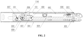
FIG. 2 is a schematic diagram of an ISOFIX mechanism in a locked state according to an embodiment of the present invention. -
FIG. 3 is a schematic diagram of an ISOFIX mechanism in a lock released state according to an embodiment of the present invention. -
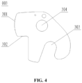
FIG. 4 is a schematic diagram of a fastening member of an ISOFIX mechanism according to an embodiment of the present invention. -
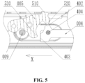
FIG. 5 is a partially enlarged schematic view of an ISOFIX mechanism according to an embodiment of the present invention. -
FIG. 6 is a schematic diagram of a locking member of an ISOFIX mechanism according to an embodiment of the present invention. - Reference numerals: 001 - sleeve; 101 - locking slot; 002 - shell; 003 - fastening member; 301 - first contact surface; 302 - second contact surface; 303 - hooking groove; 304 - mounting hole; 004 - connecting rod; 401 - first pushing portion; 402 - limiting portion; 403 - second abutting portion; 404 - release operating member; 005 - locking member; 501 - clearance groove; 502 - limiting groove; 510 - locking protrusion; 511 - first limiting end surface; 512 - second limiting end surface; 520 - first protruding portion; 530 - second protruding portion; 540 - shaft hole; 550 - eccentric protrusion; 551 - limiting hole; 006 - shaft rod; 007 - first elastic device; 008 - second elastic device; 009 - limiting member.
- The technical solutions of the present invention will be described clearly and fully with reference to the accompanying drawings. Apparently, the embodiments described are some preferred embodiments, rather than all of the embodiments of the present invention. All other embodiments obtained by a person of ordinary skill in the art without creative efforts based on the embodiments of the present invention shall fall within the protection scope of the present invention.
- In the description of the present invention, it should be noted that the orientation or positional relationships indicated by the terms "center", "upper", "lower", "left", "right", "vertical", "horizontal", "inner", "outer", etc. are based on the orientation or positional relationships shown in the drawings, and are only for the convenience of describing the present invention and simplifying the description, rather than indicating or implying that the apparatus or element described must have a specific orientation or be constructed and operated in a specific orientation, and therefore are not to be construed as limiting the present invention. In addition, the terms "first" and "second" are used herein for purposes of description, and are not intended to indicate or imply relative importance. A physical quantity in a formula, if not marked separately, should be understood as a basic quantity of a basic unit of the International System of Units, or a derived quantity derived from the basic quantity through mathematical operations such as multiplication, division, differentiation, or integration.
- In the description of the present invention, it should be noted that, unless otherwise clearly specified and defined, the terms "mount", "connect", "couple", and variants thereof should be interpreted in a broad sense, for example, may be a fixed connection, a detachable connection, or an integral connection; may be a mechanical connection or an electrical connection; or may be a direct connection, an indirectly connection via an intermediate medium, or communication between the interiors of two components. For those of ordinary skill in the art, the specific meanings of the above terms in the present invention can be understood according to specific circumstances.
- As shown in
FIG. 1 , this embodiment of the present invention provides an ISOFIX mechanism, including asleeve 001, ashell 002, afastening member 003, a connectingrod 004, and alocking member 005. Theshell 002 is slidably connected in thesleeve 001. The connectingrod 004 includes a first pushingportion 401 and a limitingportion 402, and thefastening member 003, the connectingrod 004, and the lockingmember 005 are each movably connected in theshell 002. - In an unlocked state, the
fastening member 003 are in a non-engaging state, the lockingmember 005 is locked on thesleeve 001, the first pushingportion 401 abuts against thefastening member 003, and the limitingportion 402 abuts against the lockingmember 005 to prevent the lockingmember 005 from detaching from thesleeve 001. - Specifically, under the condition that the first pushing
portion 401 abuts against thefastening member 003, the position of the connectingrod 004 can be kept stable, that is, the connectingrod 004 cannot move toward the right side inFIG. 1 , so as to prevent the limitingportion 402 from deviating relative to the lockingmember 005. Therefore, the limitingportion 402 remains in the state of abutting against the lockingmember 005. The pushing action of the limitingportion 402 prevents the lockingmember 005 from detaching from thesleeve 001, which can ensure that the lockingmember 005 is always locked on thesleeve 001 to limit the sliding of theshell 002 along thesleeve 001, providing a function of locking the length dimension of the ISOFIX mechanism. - It should be noted that, in the unlocked state, the locking
member 005 is limited by the limitingportion 402, which can prevent the lockingmember 005 from detaching from thesleeve 001 due to squeezing or collision, thereby fixing theshell 002 relative to thesleeve 001. In this way, the length dimension of the ISOFIX mechanism is locked, and the ISOFIX mechanism can be connected to an anchor point on a vehicle by pushing and pressing. After the ISOFIX mechanism is connected to the anchor point on the vehicle, thefastening member 003 is switched to the engaging state. - As shown in
FIG. 1 andFIG. 3 , the connectingrod 004 further includes a secondabutting portion 403. When an external force acts on the connectingrod 004 in a lock releasing direction (x direction inFIG. 1 ), the ISOFIX mechanism switches from the unlocked state to a lock released state, the limitingportion 402 gives a way to the lockingmember 005, and the second abuttingportion 403 abuts against the lockingmember 005 and causes the lockingmember 005 to be unlocked relative to thesleeve 001. In the unlocked state and the lock released state, thefastening member 003 is always kept in the non-engaging state. - It should be noted that a
release operating member 404 is mounted on the connectingrod 004, and therelease operating member 404 passes through theshell 002 and thesleeve 001 to extend to an outside of thesleeve 001, thesleeve 001 and/or theshell 002 are/is provided with a sliding groove, and therelease operating member 404 is slidably engaged in the sliding groove. - In an implementation, one of the
sleeve 001 and theshell 002 is provided with a sliding groove, and the other is provided with a groove opening, and the sliding groove is opposite to the groove opening. Therelease operating member 404 extends to the outside of thesleeve 001 through the sliding groove and the groove opening, and therelease operating member 404 is slidable along the sliding groove. An operator may touch therelease operating member 404 outside thesleeve 001, and operate therelease operating member 404 to slide in the x-direction inFIG. 1 . - In another implementation, the
sleeve 001 and theshell 002 are respectively provided with two sliding grooves, the two sliding grooves are arranged opposite to each other, therelease operating member 404 extends to the outside of thesleeve 001 through the two sliding grooves, and therelease operating member 404 is slidable along the sliding grooves. - When the
release operating member 404 is manually operated to slide toward the left side inFIG. 1 , the second abuttingportion 403 pushes against the lockingmember 005 and causes the lockingmember 005 to be unlocked relative to thesleeve 001, and the connectingrod 004 pulls thefastening member 003 through the secondelastic device 008, so that thefastening member 003 can be switched to the non-engaging state. - As shown in
FIG. 2 , the ISOFIX mechanism is switched to a locked state. In this case, although the lockingmember 005 is locked on thesleeve 001, the limitingportion 402 gives a way to the lockingmember 005, so that the lockingmember 005 is no longer locked. In addition, thefastening member 003 is switched to the engaging state, and the first pushingportion 401 is inserted into a locking portion of thefastening member 003, so that thefastening member 003 is locked in the engaging state. - As shown in
FIG. 1 ,FIG. 2 ,FIG. 3 , andFIG. 6 , a firstelastic device 007 is mounted on theshell 002, and the firstelastic device 007 is connected to the lockingmember 005. The firstelastic device 007 has a tendency to lock the lockingmember 005 to thesleeve 001. - In an implementation, the locking
member 005 is slidably connected to theshell 002, to achieve insertion/removal of the lockingprotrusion 510 into/from alocking slot 101. - In this implementation, a
shaft rod 006 is mounted on theshell 002, and the lockingmember 005 is rotatably connected to theshaft rod 006. The lockingmember 005 is provided with ashaft hole 540, and theshaft rod 006 is inserted into theshaft hole 540, so that the lockingmember 005 can rotate about theshaft rod 006, to achieve insertion/removal of the lockingprotrusion 510 into/from thelocking slot 101. - Specifically, the first
elastic device 007 includes a tension spring or a torsion spring, the lockingmember 005 is provided with a limitinghole 551, an end of the firstelastic device 007 is inserted into the limitinghole 551, and an elastic force of the firstelastic device 007 acts on the lockingmember 005, so that the lockingprotrusion 510 of the lockingmember 005 remains in a state of being inserted in thelocking slot 101. The secondabutting portion 403 is arranged on an end of the connectingrod 004 away from the first pushingportion 401. When the second abuttingportion 403 pushes the second protrudingportion 530, the lockingmember 005 overcomes the elastic force of the firstelastic device 007 and rotates about theshaft rod 006, so that the lockingprotrusion 510 can be pulled out from thelocking slot 101. - As shown in
FIG. 1 ,FIG. 2 , andFIG. 3 , a secondelastic device 008 is mounted in theshell 002, the secondelastic device 008 is connected to thefastening member 003, and the secondelastic device 008 has a tendency of causing thefastening member 003 to switch from an engaging state to the non-engaging state. - Specifically, the second
elastic device 008 includes a tension spring or a torsion spring, an end of the secondelastic device 008 is connected to thefastening member 003, and an elastic force of the secondelastic device 008 acts on thefastening member 003, so that thefastening member 003 can be kept in the non-engaging state. - As shown in
FIG. 1 ,FIG. 2 ,FIG. 3 , andFIG. 4 , thefastening member 003 is provided with a hookinggroove 303. When the ISOFIX mechanism is connected to an anchor point on a vehicle, a locking pin is pushed against thefastening member 003 and is inserted into the hookinggroove 303, to push thefastening member 003 to switch from the non-engaging state to the engaging state, so that the locking pin can be limited in the hookinggroove 303. - The
fastening member 003 is provided with a mountinghole 304, a pin shaft is mounted on theshell 002, and the mountinghole 304 is sleeved on the pin shaft, so that thefastening member 003 can rotate about the pin shaft. When the ISOFIX mechanism is connected to an anchor point on a vehicle, a locking pin of the anchor point on the vehicle is pushed against thefastening member 003, so that thefastening member 003 rotates around the pin shaft, to cause the locking pin to be limited in the hookinggroove 303, thereby achieving the switching of thefastening member 003 from the non-engaging state to the engaging state. - As shown in
FIG. 1 ,FIG. 2 ,FIG. 3 , andFIG. 4 , the secondelastic device 008 is connected between the fasteningmember 003 and the connectingrod 004, and the secondelastic device 008 has a tendency to cause the connectingrod 004 to move opposite to the lock releasing direction x and causes the connectingrod 004 to abut against thefastening member 003 to abut or lock thefastening member 003. - Specifically, the second
elastic device 008 has an elastic force that pulls thefastening member 003 and the connectingrod 004 to move toward each other. Under the action of the elastic force of the secondelastic device 008, thefastening member 003 not only tends to maintain the non-engaging state, but also can elastically pull the connectingrod 004 to move opposite to the lock releasing direction x. When thefastening member 003 is in the non-engaging state, the first pushingportion 401 abuts against thefastening member 003, and thefastening member 003 can prevent the connectingrod 004 from moving opposite to the lock releasing direction x, i.e., from moving toward the right side ofFIG. 1 . When the fastening member is in the engaging state, the first pushingportion 401 is inserted into the locking portion of thefastening member 003, to lock thefastening member 003 in the engaging state. - As shown in
FIG. 1 ,FIG. 2 ,FIG. 3 ,FIG. 5 , andFIG. 6 , thesleeve 001 is provided with a plurality of lockingslots 101, and the plurality of lockingslots 101 are arranged at intervals along an extending direction of thesleeve 001. The lockingmember 005 is provided with a lockingprotrusion 510 matching with each of the lockingslots 101. When theshell 002 slides along thesleeve 001, the length dimension of the ISOFIX mechanism increases or decreases. When the lockingprotrusion 510 is inserted in alocking slot 101 of the lockingslots 101, the lockingmember 005 is locked on thesleeve 001, so that theshell 002 can be fixed relative to thesleeve 001, thereby locking the length dimension of the ISOFIX mechanism. When the lockingprotrusion 510 is detached from thelocking slot 101, theshell 002 can slide relative to thesleeve 001, and theshell 002 can be extended or retracted relative to thesleeve 001, so that the length dimension of the ISOFIX mechanism can be adjusted. - As shown in
FIG. 1 ,FIG. 2 ,FIG. 3 ,FIG. 5 , andFIG. 6 , the lockingmember 005 further includes a first protrudingportion 520. In the unlocked state, the limitingportion 402 abuts against the first protrudingportion 520, thereby completely locking the lockingmember 005. In a lock released state or a locked state, the limitingportion 402 is staggered from the first protrudingportion 520. In the locked state, the lockingprotrusion 510 is inserted in thelocking slot 101, but the limitingportion 402 is staggered from the first protrudingportion 520, and the lockingmember 005 is not locked by the limitingportion 402, so that the lockingmember 005 is semi-locked. In the lock released state, the second abuttingportion 403 pushes against the lockingmember 005 and causes the lockingprotrusion 510 to be pulled out from thelocking slot 101. During this process, the limitingportion 402 is staggered from the first protrudingportion 520, so that the lockingmember 005 can be unlocked relative to thesleeve 001. - Further, the locking
member 005 is provided with aclearance groove 501, and theclearance groove 501 is located on a side of the first protrudingportion 520 away from thefastening member 003. From the unlocked state to the locked state, the limitingportion 402 moves relative to the first protrudingportion 520 toward a direction away from theclearance groove 501. From the unlocked state to the lock released state, the limitingportion 402 moves relative to the first protrudingportion 520 toward an inside of theclearance groove 501. - Further, the locking
member 005 further includes a second protrudingportion 530. From the unlocked state to the lock released state, the connectingrod 004 abuts against the second protrudingportion 530, and causes the lockingprotrusion 510 to detach from each of the lockingslots 101. - In this implementation, a
shaft rod 006 is mounted on theshell 002, the lockingmember 005 is rotatably connected to theshaft rod 006, the first protrudingportion 520 and the second protrudingportion 530 are arranged at intervals around theshaft rod 006, and theclearance groove 501 is formed between the first protrudingportion 520 and the second protrudingportion 530. The lockingmember 005 is provided with ashaft hole 540, and theshaft rod 006 is inserted into theshaft hole 540, so that the lockingmember 005 can rotate about theshaft rod 006, to achieve insertion/removal of the lockingprotrusion 510 into/from thelocking slot 101. The lockingprotrusion 510, the second protrudingportion 530, and theeccentric protrusion 550 are each arranged on the lockingmember 005, and the lockingprotrusion 510, the second protrudingportion 530, and theeccentric protrusion 550 are arranged at intervals around theshaft hole 540. The first protrudingportion 520 faces away from the lockingprotrusion 510, and theclearance groove 501 is located between the first protrudingportion 520 and the second protrudingportion 530. With the arrangement of theclearance groove 501 between the first protrudingportion 520 and the second protrudingportion 530, in the lock released state, an external force is applied to drive the connectingrod 004 to move along the lock releasing direction x, and the limitingportion 402 is staggered from the first protrudingportion 520. When the second abuttingportion 403 pushes against the second protrudingportion 530 and causes the lockingmember 005 to rotate about theshaft rod 006, the lockingprotrusion 510 can be detached from thelocking slot 101 and the limitingportion 402 can enter into theclearance groove 501. - As shown in
FIG. 1 ,FIG. 2 ,FIG. 3 , andFIG. 4 , thefastening member 003 is rotatably connected in theshell 002, and thefastening member 003 includes afirst contact surface 301. Thefirst contact surface 301 includes an arc surface. - In an implementation, the arc surface is coaxial with a rotating shaft of the
fastening member 003, and the connectingrod 004 keeps its position unchanged during thefastening member 003 switching from the engaging state to the non-engaging state. During the process of thefastening member 003 being gradually connected to the anchor point on the vehicle, the locking pin at the anchor point on the vehicle is pushed against thefastening member 003 to cause thefastening member 003 to swing. During this process, the elastic force of the secondelastic device 008 causes the first pushingportion 401 to abut against the arc surface, so that the connectingrod 004 does not move along the lock releasing direction x, and the limitingportion 402 can keep abutting against the first protrudingportion 520 of the lockingmember 005. - In another implementation, an axis of the arc surface is spaced from an axis of the rotating shaft of the
fastening member 003, so that during thefastening member 003 switching from the non-engaging state to the engaging state, the connectingrod 004 has a headroom to move opposite to the lock releasing direction. - During the
fastening member 003 switching from the non-engaging state to the engaging state, the first pushingportion 401 abuts against the arc surface. During thefastening member 003 switching from the non-engaging state to the engaging state, the secondelastic device 008 pulls the connectingrod 004 to move opposite to the lock releasing direction x (toward the right side inFIG. 1 ), so that the first pushingportion 401 always abuts against the arc surface. During this process, the firstelastic device 007 causes the lockingmember 005 to keep being locked to thesleeve 001, i.e., the lockingmember 005 is kept in the locked state by the elastic force of the firstelastic device 007, thereby maintaining the state in which the lockingprotrusion 510 is inserted in thelocking slot 101. - As shown in
FIG. 1 ,FIG. 4 , andFIG. 5 , in the lock releasing direction x, an end surface of the limitingportion 402 facing toward the lockingmember 005 is inclined in a direction avoiding the lockingmember 005. - Specifically, along the lock releasing direction x, an end surface of the limiting
portion 402 facing toward the first protrudingportion 520 is inclined in a direction away from the first protrudingportion 520. Under the pulling action of the secondelastic device 008, the connectingrod 004 always abuts against thefirst contact surface 301. During the process of thefastening member 003 being gradually connected to the anchor point on the vehicle, the locking pin at the anchor point on the vehicle is pushed against thefastening member 003 to cause thefastening member 003 to swing. During this process, the connectingrod 004 moves opposite to the lock releasing direction x, i.e., toward the right side inFIG. 1 , and the inclined surface of the limitingportion 402 gives a way to the first protrudingportion 520, thereby preventing the movements of the lockingmember 005, the connectingrod 004, and thefastening member 003 from interfering with each other. - It should be explained that during the switching from the unlocked state to the locked state, the limiting
portion 402 abuts against the first protrudingportion 520, and the first protrudingportion 520 can prevent the connectingrod 004 from moving along the lock releasing direction x. During thefastening member 003 switching from the non-engaging state to the engaging state, thefastening member 003 does not push the connectingrod 004 to move along the lock releasing direction x, thereby ensuring the smooth rotation of thefastening member 003. - As shown in
FIG. 1 ,FIG. 2 ,FIG. 3 ,FIG. 5 , andFIG. 6 , a limitingmember 009 is mounted on theshell 002, the lockingmember 005 is provided with a limitinggroove 502, and the limitingmember 009 is located in the limitinggroove 502. The limitingmember 009 is limited in the limitinggroove 502, so that the lockingmember 005 is limited during switching between working positions. - Further, the locking
member 005 further includes aneccentric protrusion 550, the second protrudingportion 530 is spaced apart from theeccentric protrusion 550, and the limitinggroove 502 is formed between the second protrudingportion 530 and theeccentric protrusion 550. When the lockingmember 005 is locked on thesleeve 001, the limitingmember 009 abuts against theeccentric protrusion 550. When the lockingmember 005 is unlocked relative to thesleeve 001, the limitingmember 009 abuts against the second protrudingportion 530. - In an implementation, a gap is provided between the limiting
member 009 and the end surface of the limitinggroove 502 facing toward the limitingmember 009, so that during rotation of the lockingmember 005 about theshaft rod 006, no friction occurs between the lockingmember 005 and the limitingmember 009. - In another implementation, the end surface of the limiting
groove 502 facing toward the limitingmember 009 is configured as an arc-shaped surface, and the arc-shaped surface is coaxial with theshaft rod 006. The limitingmember 009 is rotatably connected to a limiting shaft rod on theshell 002. During the rotation of the lockingmember 005 about theshaft rod 006, the arc-shaped surface rubs the limiting shaft rod and causes the limiting shaft rod to rotate about its own axis, thereby reducing the frictional resistance received by the lockingmember 005. - Further, the
eccentric protrusion 550 is provided with a limitinghole 551, the firstelastic device 007 is a tension spring, one end of the tension spring is connected to theshell 002, and the other end of the tension spring is connected into the limitinghole 551. The firstelastic device 007 drives the lockingmember 005 to rotate about theshaft rod 006 and causes the lockingprotrusion 510 to tend to be inserted into thelocking slot 101. - Further, the locking
protrusion 510 has a first limitingend surface 511 and a second limitingend surface 512, and the first limitingend surface 511 is opposite to the second limitingend surface 512. When the lockingprotrusion 510 is inserted in thelocking slot 101, the first limitingend surface 511 and the second limitingend surface 512 are both limited in thelocking slot 101, so that theshell 002 cannot slide relative to thesleeve 001, thereby fixing the length dimension of the ISOFIX mechanism. The first limitingend surface 511 abuts against an inner wall surface of thelocking slot 101, which can prevent theshell 002 from retracting toward inside of thesleeve 001, thereby preventing the length dimension of the ISOFIX mechanism from being shortened. In addition, the second limitingend surface 512 abuts against the inner wall surface of thelocking slot 101, which can prevent theshell 002 from being stretched toward the outside of thesleeve 001, thereby fixing the length dimension of the ISOFIX mechanism. - As shown in
FIG. 1 ,FIG. 2 ,FIG. 3 , andFIG. 4 , thefastening member 003 has asecond contact surface 302, and thefirst contact surface 301 and thesecond contact surface 302 are arranged at intervals around a circumferential direction of the mountinghole 304. - In the unlocked state, the first pushing
portion 401 abuts against thefirst contact surface 301, to prevent the connectingrod 004 from moving toward the right side inFIG. 1 . - In the locked state, the
fastening member 003 rotates about an axis of the mountinghole 304 and causes the first pushingportion 401 to detach from thefirst contact surface 301, and then under a pulling force of the secondelastic device 008, the connectingrod 004 slides toward thefastening member 003 and causes the first pushingportion 401 to abut against thesecond contact surface 302. Thesecond contact surface 302 extends along a radial direction of thefirst contact surface 301. When the first pushingportion 401 abuts against thesecond contact surface 302, thefastening member 003 can be prevented from rotating about the axis of the mountinghole 304, thereby locking thefastening member 003 in the engaging state. - This embodiment of the present invention provides a safety seat, including the ISOFIX mechanism provided in the above implementations.
- Before use, first, the ISOFIX mechanism is placed in a lock released position shown in
FIG. 1 , and the limitingportion 402 abuts against the lockingmember 005, so that the lockingmember 005 is in a fully locked state, i.e., the lockingmember 005 is locked in thelocking slot 101, and the lockingmember 005 can be prevented from detaching from thelocking slot 101, thereby fixing the length dimension of the ISOFIX mechanism. At the same time, the elastic force of the second elastic device acts on thefastening member 003, so that thefastening member 003 is kept in the non-engaging state. When the safety seat is mounted on a vehicle, the ISOFIX mechanism is operated to connect to an anchor point on the vehicle, and the locking pin at the anchor point on the vehicle abuts against thefastening member 003, so as to push thefastening member 003 to switch from the non-engaging state to the engaging state. Referring toFIG. 1 ,FIG. 2 ,FIG. 4 , andFIG. 6 , when thefastening member 003 is in the engaging state, the secondelastic device 008 pulls the connectingrod 004, to cause the first pushingportion 401 to abut against thesecond contact surface 302, so that thefastening member 003 can be limited in the engaging state. In this case, the lockingmember 005 is in a semi-locked state, and the elastic force of the firstelastic device 007 acts on the lockingmember 005, so as to cause the lockingprotrusion 510 to be inserted into thelocking slot 101. The connectingrod 004 is deviated in a direction away from the lockingmember 005, so that the limitingportion 402 is staggered from the first protrudingportion 520. At this time, the connectingrod 004 no longer has the function of locking the lockingmember 005. Referring toFIG. 3 ,FIG. 5 , andFIG. 6 , when therelease operating member 404 is pulled to move along the lock releasing direction x, the second abuttingportion 403 pushes against the second protrudingportion 530 to cause the lockingmember 005 to rotate about theshaft rod 006, until the lockingprotrusion 510 is pulled out from thelocking slot 101. In this case, theshell 002 slides and contracts relative to thesleeve 001, and the first pushingportion 401 detaches from thesecond contact surface 302. Under the pulling action of the secondelastic device 008, thefastening member 003 swings to the non-engaging state to release the locking pin of the anchor point on the vehicle, so that the ISOFIX mechanism can be removed from the anchor point on the vehicle. After therelease operating member 404 is released, thefastening member 003 is kept in the non-engaging state under the elastic force of the secondelastic device 008. The secondelastic device 008 pulls the connectingrod 004 and causes the first pushingportion 401 to abut against thefirst contact surface 301. At the same time, the elastic force of the firstelastic device 007 acts on the lockingmember 005 and causes the lockingprotrusion 510 to be inserted into thelocking slot 101, and the limitingportion 402 abuts against the first protrudingportion 520, thereby automatically returning to the locked state shown inFIG. 1 . - Finally, it should be noted that the above embodiments are intended to illustrate, instead of limiting the technical solution of the present invention. Although the present invention is described in detail by way of examples, it should be understood by those of ordinary skill in the art that modifications may be made to the technical solutions described in the embodiments, and equivalents may be substituted for some or all the technical features, without essentially departing from the scope of the technical solution described in the embodiments of the present invention.
Claims (17)
- An ISOFIX mechanism, comprising: a sleeve (001), a shell (002), a fastening member (003), a connecting rod (004), and a locking member (005), whereinthe shell (002) is slidably connected in the sleeve (001);the connecting rod (004) comprises a first pushing portion (401) and a limiting portion (402), and the fastening member (003), the connecting rod (004), and the locking member (005) are each movably connected in the shell (002);in an unlocked state, the fastening member (003) is in a non-engaging state, the locking member (005) is locked on the sleeve (001), the first pushing portion (401) abuts against the fastening member (003), and the limiting portion (402) abuts against the locking member (005) to prevent the locking member (005) from detaching from the sleeve (001).
- The ISOFIX mechanism according to claim 1, wherein the connecting rod (004) further comprises a second abutting portion (403);
when an external force acts on the connecting rod (004) in a lock releasing direction, the ISOFIX mechanism switches from the unlocked state to a lock released state, the limiting portion (402) gives a way to the locking member (005), and the second abutting portion (403) abuts against the locking member (005) and causes the locking member (005) to be unlocked relative to the sleeve (001). - The ISOFIX mechanism according to claim 1, wherein a release operating member (404) is mounted on the connecting rod (004), and the release operating member (404) passes through the shell (002) and the sleeve (001) to extend to an outside of the sleeve (001);
the sleeve (001) and/or the shell (002) are/is provided with a sliding groove, and the release operating member (404) is slidably engaged in the sliding groove. - The ISOFIX mechanism according to claim 1, wherein a first elastic device (007) is mounted on the shell (002), and the first elastic device (007) is connected to the locking member (005); and
the first elastic device (007) has a tendency to lock the locking member (005) to the sleeve (001). - The ISOFIX mechanism according to claim 1, wherein a second elastic device (008) is mounted in the shell (002), the second elastic device (008) is connected to the fastening member (003), and the second elastic device (008) has a tendency of causing the fastening member (003) to switch from an engaging state to the non-engaging state.
- The ISOFIX mechanism according to claim 5, wherein the second elastic device (008) is connected between the fastening member (003) and the connecting rod (004), and the second elastic device (008) has a tendency to cause the connecting rod (004) to move opposite to a lock releasing direction and causes the connecting rod (004) to abut against the fastening member (003) to abut or lock the fastening member (003).
- The ISOFIX mechanism according to claim 1 or 5, wherein the fastening member (003) is rotatably connected in the shell (002), and the fastening member (003) comprises a first contact surface (301);the first contact surface (301) comprises an arc surface;the arc surface is coaxial with a rotating shaft of the fastening member (003);alternatively, an axis of the arc surface is spaced from an axis of the rotating shaft of the fastening member (003), so that during the fastening member (003) switching from the non-engaging state to an engaging state, the connecting rod (004) has a headroom to move opposite to a lock releasing direction.
- The ISOFIX mechanism according to claim 7, wherein during the fastening member (003) switching from the non-engaging state to the engaging state, the first pushing portion (401) abuts against the arc surface.
- The ISOFIX mechanism according to claim 7, wherein in the lock releasing direction, an end surface of the limiting portion (402) facing toward the locking member (005) is inclined in a direction avoiding the locking member (005).
- The ISOFIX mechanism according to claim 1, wherein the sleeve (001) is provided with a plurality of locking slots (101), and the plurality of locking slots (101) are arranged at intervals; and
the locking member (005) is provided with a locking protrusion (510) matching with each of the locking slots (101). - The ISOFIX mechanism according to claim 10, wherein the locking member (005) further comprises a first protruding portion (520);in the unlocked state, the limiting portion (402) abuts against the first protruding portion (520);in a lock released state or a locked state, the limiting portion (402) is staggered from the first protruding portion (520).
- The ISOFIX mechanism according to claim 11, wherein the locking member (005) is provided with a clearance groove (501), and the clearance groove (501) is located on a side of the first protruding portion (520) away from the fastening member (003);from the unlocked state to the locked state, the limiting portion (402) moves relative to the first protruding portion (520) toward a direction away from the clearance groove (501); andfrom the unlocked state to the lock released state, the limiting portion (402) moves relative to the first protruding portion (520) toward an inside of the clearance groove (501).
- The ISOFIX mechanism according to claim 12, wherein the locking member (005) further comprises a second protruding portion (530); and
from the unlocked state to the lock released state, the connecting rod (004) abuts against the second protruding portion (530), and causes the locking protrusion (510) to detach from each of the locking slots (101). - The ISOFIX mechanism according to claim 13, wherein a shaft rod (006) is mounted on the shell (002), the locking member (005) is rotatably connected to the shaft rod (006), the first protruding portion (520) and the second protruding portion (530) are arranged at intervals around the shaft rod (006), and the clearance groove (501) is formed between the first protruding portion (520) and the second protruding portion (530).
- The ISOFIX mechanism according to claim 13, wherein a limiting member (009) is mounted on the shell (002), the locking member (005) is provided with a limiting groove (502), and the limiting member (009) is located in the limiting groove (502).
- The ISOFIX mechanism according to claim 15, wherein the locking member (005) further comprises an eccentric protrusion (550), the second protruding portion (530) is spaced apart from the eccentric protrusion (550), and the limiting groove (502) is formed between the second protruding portion (530) and the eccentric protrusion (550);when the locking member (005) is locked on the sleeve (001), the limiting member (009) abuts against the eccentric protrusion (550); andwhen the locking member (005) is unlocked relative to the sleeve (001), the limiting member (009) abuts against the second protruding portion (530).
- A safety seat, comprising the ISOFIX mechanism according to any one of claims 1-16.
Applications Claiming Priority (1)
| Application Number | Priority Date | Filing Date | Title |
|---|---|---|---|
| CN202111423489.XA CN113954707B (en) | 2021-11-26 | 2021-11-26 | ISOFIX mechanism and safety seat |
Publications (1)
| Publication Number | Publication Date |
|---|---|
| EP4186748A1 true EP4186748A1 (en) | 2023-05-31 |
Family
ID=79472091
Family Applications (1)
| Application Number | Title | Priority Date | Filing Date |
|---|---|---|---|
| EP22189207.8A Pending EP4186748A1 (en) | 2021-11-26 | 2022-08-08 | International standards organization fix (isofix) mechanism and safety seat comprising same |
Country Status (5)
| Country | Link |
|---|---|
| EP (1) | EP4186748A1 (en) |
| JP (1) | JP7320655B2 (en) |
| KR (1) | KR20230078492A (en) |
| CN (1) | CN113954707B (en) |
| TW (1) | TWI825883B (en) |
Cited By (1)
| Publication number | Priority date | Publication date | Assignee | Title |
|---|---|---|---|---|
| CN109398180A (en) * | 2018-12-18 | 2019-03-01 | 麦克英孚(宁波)婴童用品有限公司 | A kind of ISOFIX locking releasing mechanism and the child safety seat using it |
Families Citing this family (4)
| Publication number | Priority date | Publication date | Assignee | Title |
|---|---|---|---|---|
| CN114575686B (en) * | 2022-03-14 | 2023-06-30 | 奇瑞商用车(安徽)有限公司 | Side-picking door lock device, assembly method thereof and vehicle |
| SE546227C2 (en) * | 2022-06-03 | 2024-07-16 | Holmbergs Safety System Holding Ab | Adjustable connecting bar for child safety seat in vehicle, adjustable mounting arrangement, and child safety seat |
| CN115919394B (en) * | 2022-12-27 | 2024-03-12 | 宝玛医疗科技(无锡)有限公司 | Automatic closing device and anastomat |
| CN218805366U (en) * | 2023-01-17 | 2023-04-07 | 宁波宝贝第一母婴用品有限公司 | ISOFIX mechanism and safety seat of area locking |
Citations (8)
| Publication number | Priority date | Publication date | Assignee | Title |
|---|---|---|---|---|
| EP1083084A2 (en) * | 1999-09-10 | 2001-03-14 | Margarete Schräder | Child-restraint system for a motor vehicle |
| CN105644397B (en) * | 2016-04-07 | 2017-09-05 | 宁波永驰婴童用品有限公司 | The ISOFIX components of child safety seat |
| WO2017186785A1 (en) | 2016-04-29 | 2017-11-02 | Holmbergs Safety System Holding Ab | A connecting bar for a child restraint system |
| WO2018172053A1 (en) | 2017-03-22 | 2018-09-27 | Holmbergs Safety System Holding Ab | Adjustable connecting bar for a child restraint system |
| CN109278597A (en) * | 2017-07-19 | 2019-01-29 | 程克勇 | Child safety seat connector |
| CN208576459U (en) | 2018-06-22 | 2019-03-05 | 麦克英孚(宁波)婴童用品有限公司 | A kind of ISOFIX structure and the child safety seat using it |
| CN211543318U (en) | 2019-12-11 | 2020-09-22 | 宁波环球娃娃婴童用品股份有限公司 | Isofix connector |
| CN116533843A (en) | 2023-06-13 | 2023-08-04 | 宁波宝贝第一母婴用品有限公司 | ISOFIX mechanism and safety seat |
Family Cites Families (12)
| Publication number | Priority date | Publication date | Assignee | Title |
|---|---|---|---|---|
| DE102007018101A1 (en) * | 2007-04-16 | 2008-10-23 | Faurecia Autositze Gmbh | Vehicle seat, in particular motor vehicle seat |
| CN203372091U (en) * | 2013-06-24 | 2014-01-01 | 麦克英孚(宁波)婴童用品有限公司 | Connection device for automobile ISOFIX fixed point system |
| CN105015376B (en) * | 2014-04-17 | 2017-08-08 | 宝钜儿童用品香港股份有限公司 | Fixed mechanism with safe locking structure |
| DE202015104792U1 (en) * | 2015-09-09 | 2015-12-01 | Cybex Gmbh | Child seat for attachment to a motor vehicle seat |
| CN205890613U (en) * | 2016-08-16 | 2017-01-18 | 上海路途乐科技有限公司 | Children's safety seat locking structure |
| CN107985142B (en) * | 2017-12-07 | 2024-02-27 | 宁波宝贝第一母婴用品有限公司 | ISOFIX connector and child safety seat |
| JP7094819B2 (en) * | 2018-07-31 | 2022-07-04 | 株式会社カーメイト | ISOFIX child seat |
| CN209454606U (en) * | 2018-12-18 | 2019-10-01 | 麦克英孚(宁波)婴童用品有限公司 | A kind of ISOFIX locking releasing mechanism and the child safety seat using it |
| CN110614956B (en) * | 2019-10-23 | 2023-07-18 | 安道拓(重庆)汽车部件有限公司 | Automobile seat unlocking mechanism |
| CN111873864A (en) * | 2020-02-26 | 2020-11-03 | 麦克英孚(宁波)婴童用品有限公司 | Rotary adjusting mechanism and seat |
| CN111483365A (en) * | 2020-04-27 | 2020-08-04 | 好孩子儿童用品有限公司 | Automobile seat for children |
| CN112078442B (en) * | 2020-09-22 | 2021-11-26 | 恺博(常熟)座椅机械部件有限公司 | Parallel unlocking easy-entry module |
-
2021
- 2021-11-26 CN CN202111423489.XA patent/CN113954707B/en active Active
-
2022
- 2022-07-14 KR KR1020220086712A patent/KR20230078492A/en not_active Application Discontinuation
- 2022-07-25 JP JP2022117840A patent/JP7320655B2/en active Active
- 2022-07-29 TW TW111128597A patent/TWI825883B/en active
- 2022-08-08 EP EP22189207.8A patent/EP4186748A1/en active Pending
Patent Citations (8)
| Publication number | Priority date | Publication date | Assignee | Title |
|---|---|---|---|---|
| EP1083084A2 (en) * | 1999-09-10 | 2001-03-14 | Margarete Schräder | Child-restraint system for a motor vehicle |
| CN105644397B (en) * | 2016-04-07 | 2017-09-05 | 宁波永驰婴童用品有限公司 | The ISOFIX components of child safety seat |
| WO2017186785A1 (en) | 2016-04-29 | 2017-11-02 | Holmbergs Safety System Holding Ab | A connecting bar for a child restraint system |
| WO2018172053A1 (en) | 2017-03-22 | 2018-09-27 | Holmbergs Safety System Holding Ab | Adjustable connecting bar for a child restraint system |
| CN109278597A (en) * | 2017-07-19 | 2019-01-29 | 程克勇 | Child safety seat connector |
| CN208576459U (en) | 2018-06-22 | 2019-03-05 | 麦克英孚(宁波)婴童用品有限公司 | A kind of ISOFIX structure and the child safety seat using it |
| CN211543318U (en) | 2019-12-11 | 2020-09-22 | 宁波环球娃娃婴童用品股份有限公司 | Isofix connector |
| CN116533843A (en) | 2023-06-13 | 2023-08-04 | 宁波宝贝第一母婴用品有限公司 | ISOFIX mechanism and safety seat |
Cited By (2)
| Publication number | Priority date | Publication date | Assignee | Title |
|---|---|---|---|---|
| CN109398180A (en) * | 2018-12-18 | 2019-03-01 | 麦克英孚(宁波)婴童用品有限公司 | A kind of ISOFIX locking releasing mechanism and the child safety seat using it |
| CN109398180B (en) * | 2018-12-18 | 2023-09-29 | 麦克英孚(宁波)婴童用品有限公司 | ISOFIX release locking mechanism and use its children's safety seat |
Also Published As
| Publication number | Publication date |
|---|---|
| TW202321066A (en) | 2023-06-01 |
| CN113954707A (en) | 2022-01-21 |
| TWI825883B (en) | 2023-12-11 |
| KR20230078492A (en) | 2023-06-02 |
| JP7320655B2 (en) | 2023-08-03 |
| CN113954707B (en) | 2023-01-20 |
| JP2023079155A (en) | 2023-06-07 |
Similar Documents
| Publication | Publication Date | Title |
|---|---|---|
| EP4186748A1 (en) | International standards organization fix (isofix) mechanism and safety seat comprising same | |
| US10427574B2 (en) | Vehicle headrest sliding device | |
| CN111491480B (en) | Holding releasing device | |
| KR102154721B1 (en) | Locking device | |
| CN108089654B (en) | Plug-in device and case with same | |
| KR101816681B1 (en) | Locking device for a foldable member | |
| JP6232336B2 (en) | Latch device | |
| CN110362161B (en) | Plug-in device, case adopting plug-in device and electronic device | |
| WO2020027145A1 (en) | Isofix child safety seat | |
| CN214848440U (en) | Circuit breaker locking mechanical system and circuit breaker | |
| CN116022043A (en) | Side-impact protection linkage mechanism, safety seat base and child safety seat | |
| CN214848442U (en) | Circuit breaker locking mechanical system and circuit breaker | |
| CN216417123U (en) | Transmission mechanism of endoscope and endoscope | |
| CN111911009B (en) | Door lock forced locking structure and door lock with same | |
| CN210027912U (en) | Folding device and unmanned aerial vehicle | |
| CN216054376U (en) | Locking mechanical system and circuit breaker | |
| EP4375135A1 (en) | Child safety seat with reversible isofix connectors | |
| CN216383434U (en) | Terminal support | |
| CN215859595U (en) | Lock rod transmission structure, glove box and automobile | |
| CN221090579U (en) | Anti-retraction ISOFIX system | |
| CN218468015U (en) | Locking mechanism | |
| CN211061740U (en) | Unlocking structure of optical module | |
| CN219262032U (en) | Lock catch structure and cabinet | |
| CN113279631B (en) | Delay trigger mechanism and lock body | |
| CN221262267U (en) | Installation locking device and plug-in circuit breaker |
Legal Events
| Date | Code | Title | Description |
|---|---|---|---|
| PUAI | Public reference made under article 153(3) epc to a published international application that has entered the european phase |
Free format text: ORIGINAL CODE: 0009012 |
|
| STAA | Information on the status of an ep patent application or granted ep patent |
Free format text: STATUS: REQUEST FOR EXAMINATION WAS MADE |
|
| 17P | Request for examination filed |
Effective date: 20220808 |
|
| AK | Designated contracting states |
Kind code of ref document: A1 Designated state(s): AL AT BE BG CH CY CZ DE DK EE ES FI FR GB GR HR HU IE IS IT LI LT LU LV MC MK MT NL NO PL PT RO RS SE SI SK SM TR |
|
| TPAC | Observations filed by third parties |
Free format text: ORIGINAL CODE: EPIDOSNTIPA |