EP4186550A1 - Mixed gas generating system - Google Patents
Mixed gas generating system Download PDFInfo
- Publication number
- EP4186550A1 EP4186550A1 EP21847288.4A EP21847288A EP4186550A1 EP 4186550 A1 EP4186550 A1 EP 4186550A1 EP 21847288 A EP21847288 A EP 21847288A EP 4186550 A1 EP4186550 A1 EP 4186550A1
- Authority
- EP
- European Patent Office
- Prior art keywords
- gas
- hydrogen
- oxygen
- mixed
- hydrogen gas
- Prior art date
- Legal status (The legal status is an assumption and is not a legal conclusion. Google has not performed a legal analysis and makes no representation as to the accuracy of the status listed.)
- Pending
Links
- 239000007789 gas Substances 0.000 claims abstract description 471
- UFHFLCQGNIYNRP-UHFFFAOYSA-N Hydrogen Chemical compound [H][H] UFHFLCQGNIYNRP-UHFFFAOYSA-N 0.000 claims abstract description 351
- MYMOFIZGZYHOMD-UHFFFAOYSA-N Dioxygen Chemical compound O=O MYMOFIZGZYHOMD-UHFFFAOYSA-N 0.000 claims abstract description 225
- 229910001882 dioxygen Inorganic materials 0.000 claims abstract description 225
- 238000002156 mixing Methods 0.000 claims abstract description 218
- XLYOFNOQVPJJNP-UHFFFAOYSA-N water Substances O XLYOFNOQVPJJNP-UHFFFAOYSA-N 0.000 claims abstract description 144
- 239000001257 hydrogen Substances 0.000 claims abstract description 101
- 229910052739 hydrogen Inorganic materials 0.000 claims abstract description 101
- QVGXLLKOCUKJST-UHFFFAOYSA-N atomic oxygen Chemical compound [O] QVGXLLKOCUKJST-UHFFFAOYSA-N 0.000 claims abstract description 85
- 239000001301 oxygen Substances 0.000 claims abstract description 85
- 229910052760 oxygen Inorganic materials 0.000 claims abstract description 85
- 230000029058 respiratory gaseous exchange Effects 0.000 claims abstract description 61
- 238000000889 atomisation Methods 0.000 claims description 52
- 239000002808 molecular sieve Substances 0.000 claims description 31
- URGAHOPLAPQHLN-UHFFFAOYSA-N sodium aluminosilicate Chemical compound [Na+].[Al+3].[O-][Si]([O-])=O.[O-][Si]([O-])=O URGAHOPLAPQHLN-UHFFFAOYSA-N 0.000 claims description 31
- 241000190070 Sarracenia purpurea Species 0.000 claims description 21
- 150000002500 ions Chemical class 0.000 claims description 16
- 239000012528 membrane Substances 0.000 claims description 16
- 239000000341 volatile oil Substances 0.000 claims description 12
- 238000001914 filtration Methods 0.000 claims description 8
- 239000008400 supply water Substances 0.000 claims description 4
- 238000010586 diagram Methods 0.000 description 30
- 208000019693 Lung disease Diseases 0.000 description 6
- 230000000694 effects Effects 0.000 description 5
- 239000013589 supplement Substances 0.000 description 5
- 230000000153 supplemental effect Effects 0.000 description 5
- 208000024891 symptom Diseases 0.000 description 5
- 101100012902 Saccharomyces cerevisiae (strain ATCC 204508 / S288c) FIG2 gene Proteins 0.000 description 4
- 201000010099 disease Diseases 0.000 description 4
- 208000037265 diseases, disorders, signs and symptoms Diseases 0.000 description 4
- 230000036541 health Effects 0.000 description 4
- 210000004072 lung Anatomy 0.000 description 4
- 238000000034 method Methods 0.000 description 3
- 230000007480 spreading Effects 0.000 description 3
- 208000017667 Chronic Disease Diseases 0.000 description 2
- 101000827703 Homo sapiens Polyphosphoinositide phosphatase Proteins 0.000 description 2
- 102100023591 Polyphosphoinositide phosphatase Human genes 0.000 description 2
- 101100233916 Saccharomyces cerevisiae (strain ATCC 204508 / S288c) KAR5 gene Proteins 0.000 description 2
- 230000003712 anti-aging effect Effects 0.000 description 2
- 239000003963 antioxidant agent Substances 0.000 description 2
- 230000003078 antioxidant effect Effects 0.000 description 2
- 235000006708 antioxidants Nutrition 0.000 description 2
- 238000009833 condensation Methods 0.000 description 2
- 230000005494 condensation Effects 0.000 description 2
- 238000013461 design Methods 0.000 description 2
- 239000003651 drinking water Substances 0.000 description 2
- 235000020188 drinking water Nutrition 0.000 description 2
- 229940079593 drug Drugs 0.000 description 2
- 239000003814 drug Substances 0.000 description 2
- 238000005868 electrolysis reaction Methods 0.000 description 2
- 238000005516 engineering process Methods 0.000 description 2
- 238000004880 explosion Methods 0.000 description 2
- 230000035876 healing Effects 0.000 description 2
- 238000004519 manufacturing process Methods 0.000 description 2
- 229910052751 metal Inorganic materials 0.000 description 2
- 239000002184 metal Substances 0.000 description 2
- 238000004064 recycling Methods 0.000 description 2
- 238000011160 research Methods 0.000 description 2
- 235000015096 spirit Nutrition 0.000 description 2
- 239000010935 stainless steel Substances 0.000 description 2
- 229910001220 stainless steel Inorganic materials 0.000 description 2
- 229910000838 Al alloy Inorganic materials 0.000 description 1
- RYGMFSIKBFXOCR-UHFFFAOYSA-N Copper Chemical compound [Cu] RYGMFSIKBFXOCR-UHFFFAOYSA-N 0.000 description 1
- 229910000570 Cupronickel Inorganic materials 0.000 description 1
- 208000026350 Inborn Genetic disease Diseases 0.000 description 1
- CBENFWSGALASAD-UHFFFAOYSA-N Ozone Chemical compound [O-][O+]=O CBENFWSGALASAD-UHFFFAOYSA-N 0.000 description 1
- 230000004308 accommodation Effects 0.000 description 1
- 230000002378 acidificating effect Effects 0.000 description 1
- 229910045601 alloy Inorganic materials 0.000 description 1
- 239000000956 alloy Substances 0.000 description 1
- 230000004075 alteration Effects 0.000 description 1
- 229910052782 aluminium Inorganic materials 0.000 description 1
- XAGFODPZIPBFFR-UHFFFAOYSA-N aluminium Chemical compound [Al] XAGFODPZIPBFFR-UHFFFAOYSA-N 0.000 description 1
- 230000003796 beauty Effects 0.000 description 1
- 238000002512 chemotherapy Methods 0.000 description 1
- 229910052802 copper Inorganic materials 0.000 description 1
- 239000010949 copper Substances 0.000 description 1
- YOCUPQPZWBBYIX-UHFFFAOYSA-N copper nickel Chemical compound [Ni].[Cu] YOCUPQPZWBBYIX-UHFFFAOYSA-N 0.000 description 1
- 238000012937 correction Methods 0.000 description 1
- 238000004200 deflagration Methods 0.000 description 1
- 230000037213 diet Effects 0.000 description 1
- 235000005911 diet Nutrition 0.000 description 1
- 230000006806 disease prevention Effects 0.000 description 1
- 235000013305 food Nutrition 0.000 description 1
- 208000016361 genetic disease Diseases 0.000 description 1
- 235000001497 healthy food Nutrition 0.000 description 1
- 231100000516 lung damage Toxicity 0.000 description 1
- 230000004199 lung function Effects 0.000 description 1
- 239000000463 material Substances 0.000 description 1
- 238000000968 medical method and process Methods 0.000 description 1
- 239000000203 mixture Substances 0.000 description 1
- 238000012986 modification Methods 0.000 description 1
- 230000004048 modification Effects 0.000 description 1
- 230000010355 oscillation Effects 0.000 description 1
- 230000003647 oxidation Effects 0.000 description 1
- 238000007254 oxidation reaction Methods 0.000 description 1
- 230000003449 preventive effect Effects 0.000 description 1
- 239000000047 product Substances 0.000 description 1
- 230000005855 radiation Effects 0.000 description 1
- 238000011084 recovery Methods 0.000 description 1
- 230000009467 reduction Effects 0.000 description 1
- 238000012216 screening Methods 0.000 description 1
- 230000036578 sleeping time Effects 0.000 description 1
- 238000001356 surgical procedure Methods 0.000 description 1
- 230000000007 visual effect Effects 0.000 description 1
Images


Classifications
-
- A—HUMAN NECESSITIES
- A61—MEDICAL OR VETERINARY SCIENCE; HYGIENE
- A61M—DEVICES FOR INTRODUCING MEDIA INTO, OR ONTO, THE BODY; DEVICES FOR TRANSDUCING BODY MEDIA OR FOR TAKING MEDIA FROM THE BODY; DEVICES FOR PRODUCING OR ENDING SLEEP OR STUPOR
- A61M16/00—Devices for influencing the respiratory system of patients by gas treatment, e.g. mouth-to-mouth respiration; Tracheal tubes
- A61M16/10—Preparation of respiratory gases or vapours
- A61M16/12—Preparation of respiratory gases or vapours by mixing different gases
-
- A—HUMAN NECESSITIES
- A61—MEDICAL OR VETERINARY SCIENCE; HYGIENE
- A61M—DEVICES FOR INTRODUCING MEDIA INTO, OR ONTO, THE BODY; DEVICES FOR TRANSDUCING BODY MEDIA OR FOR TAKING MEDIA FROM THE BODY; DEVICES FOR PRODUCING OR ENDING SLEEP OR STUPOR
- A61M16/00—Devices for influencing the respiratory system of patients by gas treatment, e.g. mouth-to-mouth respiration; Tracheal tubes
- A61M16/021—Devices for influencing the respiratory system of patients by gas treatment, e.g. mouth-to-mouth respiration; Tracheal tubes operated by electrical means
- A61M16/022—Control means therefor
- A61M16/024—Control means therefor including calculation means, e.g. using a processor
-
- A—HUMAN NECESSITIES
- A61—MEDICAL OR VETERINARY SCIENCE; HYGIENE
- A61M—DEVICES FOR INTRODUCING MEDIA INTO, OR ONTO, THE BODY; DEVICES FOR TRANSDUCING BODY MEDIA OR FOR TAKING MEDIA FROM THE BODY; DEVICES FOR PRODUCING OR ENDING SLEEP OR STUPOR
- A61M16/00—Devices for influencing the respiratory system of patients by gas treatment, e.g. mouth-to-mouth respiration; Tracheal tubes
- A61M16/10—Preparation of respiratory gases or vapours
- A61M16/1005—Preparation of respiratory gases or vapours with O2 features or with parameter measurement
- A61M16/101—Preparation of respiratory gases or vapours with O2 features or with parameter measurement using an oxygen concentrator
-
- A—HUMAN NECESSITIES
- A61—MEDICAL OR VETERINARY SCIENCE; HYGIENE
- A61M—DEVICES FOR INTRODUCING MEDIA INTO, OR ONTO, THE BODY; DEVICES FOR TRANSDUCING BODY MEDIA OR FOR TAKING MEDIA FROM THE BODY; DEVICES FOR PRODUCING OR ENDING SLEEP OR STUPOR
- A61M16/00—Devices for influencing the respiratory system of patients by gas treatment, e.g. mouth-to-mouth respiration; Tracheal tubes
- A61M16/10—Preparation of respiratory gases or vapours
- A61M16/14—Preparation of respiratory gases or vapours by mixing different fluids, one of them being in a liquid phase
- A61M16/16—Devices to humidify the respiration air
-
- B—PERFORMING OPERATIONS; TRANSPORTING
- B01—PHYSICAL OR CHEMICAL PROCESSES OR APPARATUS IN GENERAL
- B01D—SEPARATION
- B01D53/00—Separation of gases or vapours; Recovering vapours of volatile solvents from gases; Chemical or biological purification of waste gases, e.g. engine exhaust gases, smoke, fumes, flue gases, aerosols
- B01D53/02—Separation of gases or vapours; Recovering vapours of volatile solvents from gases; Chemical or biological purification of waste gases, e.g. engine exhaust gases, smoke, fumes, flue gases, aerosols by adsorption, e.g. preparative gas chromatography
- B01D53/04—Separation of gases or vapours; Recovering vapours of volatile solvents from gases; Chemical or biological purification of waste gases, e.g. engine exhaust gases, smoke, fumes, flue gases, aerosols by adsorption, e.g. preparative gas chromatography with stationary adsorbents
-
- C—CHEMISTRY; METALLURGY
- C01—INORGANIC CHEMISTRY
- C01B—NON-METALLIC ELEMENTS; COMPOUNDS THEREOF; METALLOIDS OR COMPOUNDS THEREOF NOT COVERED BY SUBCLASS C01C
- C01B13/00—Oxygen; Ozone; Oxides or hydroxides in general
- C01B13/02—Preparation of oxygen
- C01B13/0229—Purification or separation processes
- C01B13/0248—Physical processing only
- C01B13/0259—Physical processing only by adsorption on solids
- C01B13/0262—Physical processing only by adsorption on solids characterised by the adsorbent
- C01B13/027—Zeolites
-
- C—CHEMISTRY; METALLURGY
- C25—ELECTROLYTIC OR ELECTROPHORETIC PROCESSES; APPARATUS THEREFOR
- C25B—ELECTROLYTIC OR ELECTROPHORETIC PROCESSES FOR THE PRODUCTION OF COMPOUNDS OR NON-METALS; APPARATUS THEREFOR
- C25B1/00—Electrolytic production of inorganic compounds or non-metals
- C25B1/01—Products
- C25B1/02—Hydrogen or oxygen
- C25B1/04—Hydrogen or oxygen by electrolysis of water
- C25B1/044—Hydrogen or oxygen by electrolysis of water producing mixed hydrogen and oxygen gas, e.g. Brown's gas [HHO]
-
- C—CHEMISTRY; METALLURGY
- C25—ELECTROLYTIC OR ELECTROPHORETIC PROCESSES; APPARATUS THEREFOR
- C25B—ELECTROLYTIC OR ELECTROPHORETIC PROCESSES FOR THE PRODUCTION OF COMPOUNDS OR NON-METALS; APPARATUS THEREFOR
- C25B15/00—Operating or servicing cells
- C25B15/08—Supplying or removing reactants or electrolytes; Regeneration of electrolytes
-
- C—CHEMISTRY; METALLURGY
- C25—ELECTROLYTIC OR ELECTROPHORETIC PROCESSES; APPARATUS THEREFOR
- C25B—ELECTROLYTIC OR ELECTROPHORETIC PROCESSES FOR THE PRODUCTION OF COMPOUNDS OR NON-METALS; APPARATUS THEREFOR
- C25B9/00—Cells or assemblies of cells; Constructional parts of cells; Assemblies of constructional parts, e.g. electrode-diaphragm assemblies; Process-related cell features
- C25B9/17—Cells comprising dimensionally-stable non-movable electrodes; Assemblies of constructional parts thereof
- C25B9/19—Cells comprising dimensionally-stable non-movable electrodes; Assemblies of constructional parts thereof with diaphragms
- C25B9/23—Cells comprising dimensionally-stable non-movable electrodes; Assemblies of constructional parts thereof with diaphragms comprising ion-exchange membranes in or on which electrode material is embedded
-
- C—CHEMISTRY; METALLURGY
- C25—ELECTROLYTIC OR ELECTROPHORETIC PROCESSES; APPARATUS THEREFOR
- C25B—ELECTROLYTIC OR ELECTROPHORETIC PROCESSES FOR THE PRODUCTION OF COMPOUNDS OR NON-METALS; APPARATUS THEREFOR
- C25B9/00—Cells or assemblies of cells; Constructional parts of cells; Assemblies of constructional parts, e.g. electrode-diaphragm assemblies; Process-related cell features
- C25B9/70—Assemblies comprising two or more cells
- C25B9/73—Assemblies comprising two or more cells of the filter-press type
-
- A—HUMAN NECESSITIES
- A61—MEDICAL OR VETERINARY SCIENCE; HYGIENE
- A61M—DEVICES FOR INTRODUCING MEDIA INTO, OR ONTO, THE BODY; DEVICES FOR TRANSDUCING BODY MEDIA OR FOR TAKING MEDIA FROM THE BODY; DEVICES FOR PRODUCING OR ENDING SLEEP OR STUPOR
- A61M16/00—Devices for influencing the respiratory system of patients by gas treatment, e.g. mouth-to-mouth respiration; Tracheal tubes
- A61M16/0003—Accessories therefor, e.g. sensors, vibrators, negative pressure
- A61M2016/003—Accessories therefor, e.g. sensors, vibrators, negative pressure with a flowmeter
- A61M2016/0033—Accessories therefor, e.g. sensors, vibrators, negative pressure with a flowmeter electrical
- A61M2016/0039—Accessories therefor, e.g. sensors, vibrators, negative pressure with a flowmeter electrical in the inspiratory circuit
-
- A—HUMAN NECESSITIES
- A61—MEDICAL OR VETERINARY SCIENCE; HYGIENE
- A61M—DEVICES FOR INTRODUCING MEDIA INTO, OR ONTO, THE BODY; DEVICES FOR TRANSDUCING BODY MEDIA OR FOR TAKING MEDIA FROM THE BODY; DEVICES FOR PRODUCING OR ENDING SLEEP OR STUPOR
- A61M16/00—Devices for influencing the respiratory system of patients by gas treatment, e.g. mouth-to-mouth respiration; Tracheal tubes
- A61M16/10—Preparation of respiratory gases or vapours
- A61M16/1005—Preparation of respiratory gases or vapours with O2 features or with parameter measurement
- A61M2016/102—Measuring a parameter of the content of the delivered gas
- A61M2016/1035—Measuring a parameter of the content of the delivered gas the anaesthetic agent concentration
-
- A—HUMAN NECESSITIES
- A61—MEDICAL OR VETERINARY SCIENCE; HYGIENE
- A61M—DEVICES FOR INTRODUCING MEDIA INTO, OR ONTO, THE BODY; DEVICES FOR TRANSDUCING BODY MEDIA OR FOR TAKING MEDIA FROM THE BODY; DEVICES FOR PRODUCING OR ENDING SLEEP OR STUPOR
- A61M2202/00—Special media to be introduced, removed or treated
- A61M2202/02—Gases
- A61M2202/0208—Oxygen
-
- A—HUMAN NECESSITIES
- A61—MEDICAL OR VETERINARY SCIENCE; HYGIENE
- A61M—DEVICES FOR INTRODUCING MEDIA INTO, OR ONTO, THE BODY; DEVICES FOR TRANSDUCING BODY MEDIA OR FOR TAKING MEDIA FROM THE BODY; DEVICES FOR PRODUCING OR ENDING SLEEP OR STUPOR
- A61M2205/00—General characteristics of the apparatus
- A61M2205/33—Controlling, regulating or measuring
- A61M2205/3331—Pressure; Flow
- A61M2205/3334—Measuring or controlling the flow rate
-
- B—PERFORMING OPERATIONS; TRANSPORTING
- B01—PHYSICAL OR CHEMICAL PROCESSES OR APPARATUS IN GENERAL
- B01D—SEPARATION
- B01D2253/00—Adsorbents used in seperation treatment of gases and vapours
- B01D2253/10—Inorganic adsorbents
- B01D2253/116—Molecular sieves other than zeolites
-
- B—PERFORMING OPERATIONS; TRANSPORTING
- B01—PHYSICAL OR CHEMICAL PROCESSES OR APPARATUS IN GENERAL
- B01D—SEPARATION
- B01D2256/00—Main component in the product gas stream after treatment
- B01D2256/12—Oxygen
-
- B—PERFORMING OPERATIONS; TRANSPORTING
- B01—PHYSICAL OR CHEMICAL PROCESSES OR APPARATUS IN GENERAL
- B01D—SEPARATION
- B01D2259/00—Type of treatment
- B01D2259/45—Gas separation or purification devices adapted for specific applications
- B01D2259/4533—Gas separation or purification devices adapted for specific applications for medical purposes
-
- C—CHEMISTRY; METALLURGY
- C01—INORGANIC CHEMISTRY
- C01B—NON-METALLIC ELEMENTS; COMPOUNDS THEREOF; METALLOIDS OR COMPOUNDS THEREOF NOT COVERED BY SUBCLASS C01C
- C01B13/00—Oxygen; Ozone; Oxides or hydroxides in general
- C01B13/02—Preparation of oxygen
-
- Y—GENERAL TAGGING OF NEW TECHNOLOGICAL DEVELOPMENTS; GENERAL TAGGING OF CROSS-SECTIONAL TECHNOLOGIES SPANNING OVER SEVERAL SECTIONS OF THE IPC; TECHNICAL SUBJECTS COVERED BY FORMER USPC CROSS-REFERENCE ART COLLECTIONS [XRACs] AND DIGESTS
- Y02—TECHNOLOGIES OR APPLICATIONS FOR MITIGATION OR ADAPTATION AGAINST CLIMATE CHANGE
- Y02E—REDUCTION OF GREENHOUSE GAS [GHG] EMISSIONS, RELATED TO ENERGY GENERATION, TRANSMISSION OR DISTRIBUTION
- Y02E60/00—Enabling technologies; Technologies with a potential or indirect contribution to GHG emissions mitigation
- Y02E60/30—Hydrogen technology
- Y02E60/36—Hydrogen production from non-carbon containing sources, e.g. by water electrolysis
Definitions
- the present invention relates to a mixed gas generating device combined with oxygen gas generator, and more particularly, relates to a mixed gas generating device collocating with an oxygen gas generator or connected to a breathing tube to generate a mixed gas of hydrogen gas and oxygen gas.
- hydrogen gas is also used to provide inhalation for patients with lung diseases to relieve symptoms of lung damage.
- the concentration of hydrogen gas in the gas produced by the electrolysis of the hydrogen gas generating device is relatively high. Therefore, the hydrogen gas generating device usually uses the method of adding air to dilute the hydrogen gas concentration before producing it for human inhalation.
- the users are patients with lung disease, their lung functions are low and the patients need to inhale a higher concentration of oxygen gas.
- the previous hydrogen gas generating device can dilute the hydrogen gas concentration with air, it still cannot increase the oxygen gas concentration in the output gas.
- the present invention provides a mixing generating device to solve the problems of the prior art.
- the mixed gas generating device comprises a hydrogen gas generating device and an oxygen gas generator.
- the hydrogen gas generating device further comprises an electrolytic cell and an integrated water tank module.
- the electrolytic cell is configured to generate a hydrogen gas and a second oxygen gas when electrolyzing water.
- the integrated water tank module comprises a hydrogen gas port, an oxygen gas port and an water port coupled to the electrolytic cell to receive the hydrogen gas and the second oxygen gas from the electrolytic cell and supply water to the electrolytic cell.
- the hydrogen gas and the first oxygen gas are mixed to each other to form a mixed gas
- the oxygen gas generator is configured outside of the hydrogen gas generating device, the oxygen gas generator comprises an oxygen gas conduit coupled to the hydrogen gas generating device to input the first oxygen gas into the hydrogen gas generating device, so as to mix the hydrogen gas and the first oxygen gas to form the mixed gas.
- the oxygen gas generator comprises a molecular sieve filtering unit configured to filter an air to generate the first oxygen gas.
- the mixed gas generating device further comprises a gas mixing tube coupled to the hydrogen gas generating device and the oxygen gas generator to receive the hydrogen gas and the first oxygen gas, so as to mix the hydrogen gas and the first oxygen gas to form the mixed gas.
- the gas mixing tube is integrated in the integrated water tank module of the hydrogen gas generating device.
- the gas mixing tube and the oxygen gas generator are configured outside of the hydrogen gas generating device.
- the mixed gas generating device combined with oxygen gas generator further comprises a backfire preventer disposed between the oxygen gas generator and the gas mixing tube.
- the hydrogen gas generating device further comprises an atomization/volatile gas mixing tank and a flame arrester.
- the atomization/volatile gas mixing tank is coupled to the integrated water tank module to receive the hydrogen gas from the integrated water tank module.
- the atomization/volatile gas mixing tank selectively generates an atomized gas to be mixed with the hydrogen gas, wherein the atomized gas is one or a combination selected from a group consisting of a water vapor, anatomized drops, and an essential oils.
- the flame arrester is coupled to an entrance of the atomization/volatile gas mixing tank.
- the electrolytic cell further comprises a cathode chamber, a hydrogen gas output duct, an anode chamber, an oxygen gas output duct, a water input duct and an ion membrane.
- the cathode chamber is located on a first side of the electrolytic cell.
- the anode chamber is located on a second side of the electrolytic cell.
- the ion membrane is disposed between the anode chamber and the cathode chamber.
- the oxygen gas output duct is coupled to the oxygen gas port.
- the hydrogen gas output duct is coupled to the hydrogen gas port.
- the water input duct is coupled to the water port.
- the anode chamber generates the second oxygen gas and the cathode chamber generates the hydrogen gas when the electrolytic cell electrolyzes water.
- the oxygen gas output duct is coupled with the anode chamber and penetrates the second side to output the second oxygen gas at the second side
- the hydrogen gas output duct is coupled with the cathode chamber and extends toward the second side and penetrates the second side to output the hydrogen gas at the second side, so as to cause the hydrogen gas and the second oxygen gas to be outputted at the same side of the electrolytic cell
- Another scope of the present invention is to provide a mixed gas generating system.
- the mixed gas generating system comprises a hydrogen gas generating device and an oxygen generator.
- the hydrogen gas generating device further comprises an electrolytic cell, an integrated flow channel module, a condensing filter, a humidification cup and a hydrogen water cup.
- the electrolytic cell is configured to generate a hydrogen gas when electrolyzing water.
- the integrated flow channel device is coupled to the electrolytic cell.
- the condensing filter is engaged with the integrated flow channel device and configured to filter the hydrogen gas generated by the electrolytic cell.
- the humidification cup is engaged with the integrated flow channel device and configured to humidify the hydrogen gas.
- the hydrogen water cup is engaged with the integrated flow channel device and configured to accommodate water and selectively receive the hydrogen gas.
- the hydrogen gas flows into the hydrogen water cup and is mixed with the water contained in the hydrogen water cup to form a hydrogen water.
- the oxygen gas generator is configured to generate a first oxygen gas. Wherein, the hydrogen gas and the first oxygen gas are mixed to each other to form a mixed gas
- the oxygen gas generator is configured outside of the hydrogen gas generating device.
- the oxygen gas generator comprises an oxygen gas conduit coupled to the hydrogen gas generating device to input the first oxygen gas into the hydrogen gas generating device, so as to mix the hydrogen gas and the first oxygen gas to form the mixed gas.
- the oxygen gas generator comprises a molecular sieve filtering unit configured to filter an air to generate the first oxygen gas.
- the mixed gas generating system further comprises a gas mixing tube coupled to the hydrogen gas generating device and the oxygen gas generator to receive the hydrogen gas and the first oxygen gas, so as to mix the hydrogen gas and the first oxygen gas to form the mixed gas.
- the gas mixing tube is integrated in the integrated water tank module of the hydrogen gas generating device.
- the gas mixing tube and the oxygen gas generator are configured outside of the hydrogen gas generating device.
- the mixed gas generating device further comprises a backfire preventer configured between the oxygen gas generator and the gas mixing tube.
- the hydrogen gas generating device further comprises an atomization/volatile gas mixing tank and a flame arrester.
- the atomization/volatile gas mixing tank is coupled to the integrated water tank module to receive the hydrogen gas from the integrated water tank module.
- the atomization/volatile gas mixing tank selectively generates an atomized gas to be mixed with the hydrogen gas, wherein the atomized gas is one or a combination selected from a group consisting of a water vapor, anatomized drops, and an essential oils.
- the flame arrester is coupled to an entrance of the atomization/volatile gas mixing tank.
- Another scope of the present invention is to provide a mixed gas generating system.
- the mixed gas generating system comprises a hydrogen gas generating device and a breathing tube.
- the hydrogen gas generating device further comprises an electrolytic cell and an integrated water tank module.
- the electrolytic cell is configured to generate a hydrogen gas and a second oxygen gas when electrolyzing water.
- the integrated water tank module comprises a hydrogen gas port, an oxygen gas port and a water port coupled to the electrolytic cell.
- the integrated water tank module is configured to receive the hydrogen gas and the second oxygen gas from the electrolytic cell and supply water to the electrolytic cell.
- the breathing tube is coupled to the oxygen gas generator and configured to receive a first oxygen gas generated by an oxygen generating device configured outside of the hydrogen generating device. Wherein, the hydrogen gas and the first oxygen gas are mixed to each other to form a mixed gas
- the mixed gas generating system further comprises a gas mixing tube coupled to the breathing tube to mix the hydrogen gas and the first oxygen gas to form the mixed gas.
- the gas mixing tube is integrated in the integrated water tank module of the hydrogen gas generating device.
- the gas mixing tube is configured outside of the hydrogen gas generating device.
- the mixed gas generating system further comprises a backfire preventer configured in the breathing tube.
- the hydrogen gas generating device further comprises an atomization/volatile gas mixing tank and a flame arrester.
- the atomization/volatile gas mixing tank is coupled to the integrated water tank module to receive the hydrogen gas from the integrated water tank module.
- the atomization/volatile gas mixing tank selectively generates an atomized gas to be mixed with the hydrogen gas, wherein the atomized gas is one or a combination selected from a group consisting of a water vapor, anatomized drops, and an essential oils.
- the flame arrester is coupled to an entrance of the atomization/volatile gas mixing tank.
- the electrolytic cell further comprises a cathode chamber, a hydrogen gas output duct, an anode chamber, an oxygen gas output duct, a water input duct and an ion membrane.
- the cathode chamber is located on a first side of the electrolytic cell.
- the anode chamber is located on a second side of the electrolytic cell.
- the ion membrane is disposed between the anode chamber and the cathode chamber.
- the oxygen gas output duct is coupled to the oxygen gas port.
- the hydrogen gas output duct is coupled to the hydrogen gas port.
- the water input duct is coupled to the water port.
- the anode chamber generates the second oxygen gas and the cathode chamber generates the hydrogen gas when the electrolytic cell electrolyzes water.
- the oxygen gas output duct is coupled with the anode chamber and penetrates the second side to output the second oxygen gas at the second side
- the hydrogen gas output duct is coupled with the cathode chamber and extends toward the second side and penetrates the second side to output the hydrogen gas at the second side, so as to cause the hydrogen gas and the second oxygen gas to be outputted at the same side of the electrolytic cell
- Another scope of the present invention is to provide a mixed gas generating system.
- the mixed gas generating system comprises a hydrogen gas generation device and a breathing tube.
- the hydrogen gas generated device further comprises an electrolytic cell, an integrated flow channel device, a condensing filter, a humidification cup and a hydrogen water cup.
- the electrolytic cell is configured to generate a hydrogen gas when electrolyzing water.
- the integrated flow channel device is coupled to the electrolytic cell.
- the condensing filter is engaged with the integrated flow channel device.
- the condensing filter is configured to filter the hydrogen gas generated by the electrolytic cell.
- the humidification cup is engaged with the integrated flow channel device.
- the humidification cup is configured to humidify the hydrogen gas.
- the hydrogen water cup is engaged with the integrated flow channel device.
- the hydrogen water cup is configured to accommodate water and selectively receive the hydrogen gas.
- the hydrogen gas being mixed with the water contained in the hydrogen water cup to form a hydrogen water when the hydrogen gas flows into the hydrogen water cup.
- the breathing tube is coupled to the oxygen gas generator and configured to receive a first oxygen gas generated by an oxygen generating device which is configured outside of the hydrogen generating device. Wherein, the hydrogen gas and the first oxygen gas are mixed with each other to form a mixed gas.
- the mixed gas generating system further comprises a gas mixing tube coupled to the hydrogen gas generating device and the oxygen gas generator to receive the hydrogen gas and the first oxygen gas, so as to mix the hydrogen gas and the first oxygen gas to form the mixed gas.
- the gas mixing tube is integrated in the integrated water tank module of the hydrogen gas generating device.
- the gas mixing tube is configured outside of the hydrogen gas generating device.
- the mixed gas generating system further comprises a backfire preventer configured between the oxygen gas generator and the gas mixing tube
- the hydrogen gas generating device further comprises an atomization/volatile gas mixing tank and a flame arrester.
- the atomization/volatile gas mixing tank is coupled to the integrated water tank module to receive the hydrogen gas from the integrated water tank module.
- the atomization/volatile gas mixing tank selectively generates an atomized gas to be mixed with the hydrogen gas, wherein the atomized gas is one or a combination selected from a group consisting of a water vapor, anatomized drops, and an essential oils.
- the flame arrester is coupled to an entrance of the atomization/volatile gas mixing tank
- the mixing generating device with oxygen gas generator of the present invention is capable of generating oxygen gas by the oxygen gas generator and mixing the oxygen gas with the hydrogen gas produced by the electrolytic cell to dilute the hydrogen.
- the oxygen gas is mixed with the hydrogen gas to generate a mixed gas with a certain concentration of hydrogen gas for the patients with lung diseases to inhale, thus alleviating symptoms and reducing the burden on the lungs.
- the oxygen gas inputted by the oxygen gas generator makes the mixed gas having a higher oxygen concentration that is suitable for the patients with damaged lungs who requires high oxygen concentrations.
- the mixed gas produced by the device of the present invention may be mixed with the atomization gas with healing effects to from a healthy gas for human inhalation.
- the device of the present invention can prevent the backflow of gas by backfire device, thereby improving safety. Therefore, the mixed gas generating device combined with oxygen gas generator of the present invention can provide gas with multiple effects at the same time, improve the symptoms of patients with lung diseases, and also be used for general healthcare.
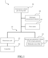
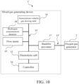
- FIG.1 illustrates a functional block diagram of the mixing generating device with oxygen gas generator 1 according to an embodiment of the present invention.
- the mixed gas generating device combined with oxygen gas generator 1 comprising an electrolytic cell 12, an oxygen gas generator 13, and a gas mixing tube 15.
- the electrolytic cell 12 is configured for electrolyzing water to produce a hydrogen gas-containing gas or the hydrogen gas.
- the gas mixing tube 15 is coupled to the electrolytic cell 12 and the atomization/volatile gas mixing tank 16 for transporting the hydrogen gas-containing gas or hydrogen gas generated by the electrolytic cell 12 to the atomizing gas/volatile gas mixing tank 16.
- the oxygen gas generator 13 comprises a molecular sieve filter 131 to filter the air and generate the oxygen gas, which is called a first oxygen gas hereafter.
- the oxygen gas generator 13 is coupled to the gas mixing tube 15 to dilute the hydrogen gas by inputting the first oxygen gas into the gas mixing tube 15 to form a mixed gas.
- the mixed gas generating device combined with oxygen gas generator 1 further comprises a hydrogen concentration detector 18 coupled with the gas mixing tube 15 to detect a gas volume concentration in the gas mixing tube 15.
- the hydrogen concentration detector 18, the electrolytic cell 12, and the oxygen gas generator 13 can be coupled to the controller 14 of mixed gas generating device combined with oxygen gas generator 1.
- the controller 14 can respectively adjust the hydrogen gas generation production quantity of the electrolytic cell 12 and the oxygen gas production quantity of the oxygen generator 13, according to the hydrogen concentration detected by the hydrogen concentration detector 18, so as to dilute and adjust the hydrogen concentration of the mixed gas in the gas mixing tube 15 to be less than a predetermined value for human inhalation.
- the predetermined value can be 1% to 7.5%, but not limited to, the inhalation of hydrogen concentration depends on user's body.
- the mixed gas generating device combined with oxygen gas generator 1 further comprises the flow meter 19.
- the flow meter19 coupled to the gas mixing tube 15 to detect the flow rate value of the mixed gas in the gas mixing tube 15.
- the flow meter 19 also can be coupled to the controller 14 as mentioned above, the controller 14 can respectively adjust the hydrogen gas generation volume of the electrolytic cell 12 and the oxygen gas generation volume of the oxygen generator 13 according to the flow rate value of the mixed gas detected by the flow meter19.
- the mixed gas generating device combined with the oxygen gas generator 1 generates the mixed gas at the predetermined flow value for the user inhalation.
- the predetermined flow value of the mixed gas can be 1.0 L/min to 6.0 L/min or above 6.0 L/min. In an embodiment, the predetermined flow value of the mixed gas can be between 3.0 L/min to 6.0 L/min.
- FIG.2 illustrates a partial graph of the mixing generating device with oxygen gas generator according to another embodiment of the present invention.
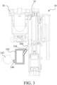
- FIG3 illustrates a cross-section of a mixing generating device with oxygen gas generator in FIG2 .
- the mixing generating device with oxygen gas generator 3 comprises the integrated water tank module30, the electrolytic cell 32, the oxygen gas generator 34, and the atomization/volatile gas mixing tank 36.
- the integrated water tank module 30 comprises the sink, the gas mixing tube 35, the hydrogen port 300, the oxygen port 302, and the water port 304.
- the hydrogen port 300 is coupled to the gas mixing tube 35 within the integrated water tank module 30, and the oxygen port 302 and water port 304 are coupled to the sink within the integrated water tank module 30.
- the hydrogen port 300, the oxygen port 302, and the water port 304 of the integrated water tank module 30 can be separately coupled to hydrogen gas output duct 320.
- the oxygen gas output duct 322 and the water input duct 324 of the electrolytic cell 32 are to respectively receive the hydrogen gas and the oxygen gas generated by the electrolytic cell 32 to supplement the electrolyzed water in the electrolytic cell 32.
- the second oxygen output of the electrolytic tank 32 may be mixed with little residual electrolyzed water, and the residual electrolyzed water remains in the water tank of the integrated water tank module 30 for recycling.
- the oxygen gas generator 34 further comprises the air conduit 340, the molecular sieve oxygen generator 342, the oxygen gas conduit 344, and the air pump 347.
- the molecular sieve filter unit 342 can be formed by a plurality of molecular sieves in the container, such as a molecular sieve filter to filter out oxygen gas in the air. Specifically, the molecular sieves adsorb gases other than oxygen gas into the air, and only allow oxygen gas to pass through.
- the air conduit 3 is coupled to the air pump 347 and the molecular sieve oxygen generator 342; the oxygen gas conduit 344 is coupled to the molecular sieve oxygen generator 342 and the gas mixing tube 35 of the integrated sink module 30.
- the air pump 347 sucks in air from the environment and passes the air through the air conduit 340 to the molecular sieve filter unit 342.
- the joint position between the supplemental gas conduit 306 and the gas mixing tube 35 has an angle, and the joint position must form an arc lead angle. In practice, the angle may be a sharp angle below 90 degrees, and a better angle range in the design is between 25 and 45 degrees.
- the molecular sieve filter unit 342 filters out the first oxygen gas in the air, and outputs the first oxygen gas to the supplemental gas conduit 306 through the oxygen gas conduit 344.
- the supplemental gas conduit 306 is designed with an angle so that the first oxygen gas in the oxygen gas conduit 344 enters into the gas mixing tube 35 to dilute the hydrogen gas in the gas mixing tube 35.
- the oxygen gas generator can be installed outside of the hydrogen generating device or inside it.
- the atomization/ volatile gas mixing tank 36 is coupled to the gas mixing tube 35 to receive the mixed gas including the hydrogen gas and oxygen gas.
- the atomization/ volatile gas mixing tank 36 generates an atomizing gas to be mixed with the mixed gas to form a healthy gas, wherein the atomizing gas is one or a combination selected from a group consisting of water vapor, anatomized drops, and essential oils.
- the atomization/volatile gas mixing tank 36 comprises an oscillator.
- the oscillator atomizes water, anatomized drops and essential oils in the atomization/volatile gas mixing tank 36 through oscillation to generate atomized gas, and to mix the gas with the atomized gas to form a health gas.
- the atomization/volatile gas mixing tank 36 can be selectively turned on or off according to users' needs to provide healthcare gas mixed with atomized gas or mixed gas (such as the hydrogen gas diluted by the second oxygen gas) for users to inhale.
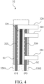
- FIG4 illustrates a cross-section of the electrolytic cell in FIG2 .
- the electrolytic cell 32 can be an ion membrane electrolytic cell. In practice, it is not limited to an ion membrane electrolytic cell. This present invention may also use other types of electrolytic cells.
- the electrolytic cell 32 comprises an ion membrane 321, a cathode chamber 325, an anode chamber 326, a first side S1, a second side S2, a hydrogen gas output duct 320, and an oxygen gas output duct 322.
- the ion membrane 321 is disposed between the first side S1 and the second side S2;
- the cathode 325 is disposed between the ion membrane 321 and the first side S1;
- the anode 326 is disposed between the ion membrane 321 and the second side S2.
- the cathode chamber 3201 the area of the first side S1 and the cathode 325 located is called the cathode chamber 3201
- the area of the second side S2 and the anode electrode 326 located is called the anode chamber 3202.
- the corresponding positions are shown by a dotted line in the FIG 3 .
- the hydrogen gas output duct 320 extends from between the ion membrane 321 and the first side S1 to the second side S2 and penetrates the second side S2
- the oxygen gas output duct 322 extends between the ion membrane 321 and the second side S2, and penetrates the second side S2.
- the cathode chamber generates the hydrogen gas and the anode chamber generates the second oxygen gas when the electrolytic cell electrolyzes water.
- the second oxygen gas contains oxygen, and may also contain the ozone that is not conducive to human inhalation, so the second oxygen gas and hydrogen gas are outputted separately.
- the hydrogen gas and the second oxygen gas generated by the electrolytic cell 32 electrolyzing water are outputted from the second side S2 of electrolytic cell 32 respectively through the hydrogen gas output duct 320 and oxygen gas output duct 322.
- the electrolytic cell 12 may comprise the water input duct 324 coupled to the anode chamber 3202 and penetrate the second side S2, to receive water to supplement the electrolyzed water lost after electrolysis. Therefore, the water input duct 324, the hydrogen gas output duct 320, and the oxygen gas output duct 322 are disposed on the second side S2 of the electrolytic cell 32.
- the hydrogen gas output duct 320, the oxygen gas output duct 322 and the water input duct 324 are disposed on one side of the anode chamber 3202 of the electrolytic cell 32 (the second side, S2), but it is not limited to this.
- the hydrogen gas output duct 320, the oxygen gas output duct 322 and the water input duct 324 can be disposed on one side of the cathode chamber 3201 of the electrolytic cell 32 (the first side S1).
- the mixing generating device with oxygen gas generator of the present invention can also include a backflow preventer device (The figure is not shown), disposed between the oxygen gas generator and the gas mixing tube, configured to prevent gas in the gas mixing tube from flowing through the oxygen generator.
- the backflow preventer device can be a flame arrester.
- the flame arrester comprises the non-return valve; therefore, the gas can pass through in one direction only.
- the backflow preventer device is disposed on the gas mixing tube and is close to the oxygen generator, so that the first oxygen gas in the oxygen gas duct can flow to the gas mixing tube through the backflow preventer device, and the gas in the gas mixing tube cannot flow into the oxygen gas duct.
- the backflow preventer device can prevent other gas in the gas mixing tube from returning back to the oxygen gas duct, thereby preventing the gas unfortunately ignited from spreading to the oxygen generator and then improving safety.
- the location of the backflow preventer device is not limited to the place mentioned above.
- the backflow preventer device can be disposed on the oxygen gas duct of the oxygen generator and close to the gas mixing tube.
- the backflow preventer device is disposed between the gas mixing tube and the atomizing gas/volatile gas mixing tank, and is disposed at the entrance of the atomizing gas/volatile gas mixing tank, to prevent the gas of the atomizing gas/volatile gas mixing tank from backflowing to the gas mixing tube.
- the flame arrester can contain at least one of a metal mesh filter and a corrugated filter.
- the metal mesh filter can be the stainless steel or the copper mesh with a diameter of 0.23 ⁇ 0.315mm and composed of multiple layers.
- the corrugated filter can be stainless steel, copper-nickel alloy, aluminum, and aluminum alloy which can be used to prevent the violent flame of deflagration and withstand the corresponding thermal and mechanical effects.
- the flame arrestor is used to block off the fire from flowing to the flame arrestor, thereby isolating the two spaces to avoid the fire spreading from one side of the flame arrester to the other side, which can cause the fire to spread through the gas flow path and make an explosion.
- the mixed gas generating device combined with an oxygen generator of the aforementioned embodiments further comprises a control panel coupled to the above-mentioned of the controller, thereby controlling the electrolytic cell and the oxygen generator and adjusting the hydrogen volume concentration and the flow rate of the mixed gas output.
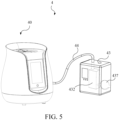
- FIG 5 illustrates a schematic diagram of a mixed gas generating device 4 according to an embodiment of the present invention.
- the difference between this embodiment and the aforementioned embodiment is that the oxygen generator 43 is coupled to hydrogen generating device 40 from the outside of the hydrogen generating device 40.
- the hydrogen generating device 40 comprises the casing, and the casing includes an accommodating space for the electrolytic cell, the integrated sink module, the atomization/ volatile gas mixing tank, and the gas mixing tube mentioned above.
- the oxygen generator 43 is disposed on the outside of the hydrogen generating device 40, comprising the molecular sieve filtering unit 432, the air pump 437 and the oxygen gas conduit 44 mentioned above (the molecular sieve filtering unit 432 and the air pump 437 are represented by the dashed lines in figure).
- the oxygen conduit 44 passes through the casing of the hydrogen generating device 40 from the outside of the hydrogen generating device 40 and coupled to the gas mixing tube located inside the casing of the hydrogen generating device 40, and the gas mixing tube is coupled to the atomization/ volatile gas mixing tank. Therefore, the oxygen generator 43, through the molecular sieve filter unit 432, inputs the first oxygen generated by the air pump 437 into the gas mixing tube to dilute the hydrogen gas to form a mixed gas.
- FIG 6 illustrates a schematic diagram of a mixed gas generating device according to another embodiment of the present invention.
- the difference between this embodiment and the aforementioned embodiment is that the gas mixing tube 55 and the oxygen generator 53 are both coupled to the hydrogen generating device 50 from the outside of the hydrogen generating device 50.
- the hydrogen generating device 50 comprises a casing, and the casing includes an accommodating space for the electrolytic cell, the integrated sink module, and the atomization/volatile gas mixing tank mentioned above.
- the atomization/ volatile gas mixing tank comprises a gas port, and the gas mixing tube 55, from the outside of the casing of the hydrogen generating device 50, is coupled to the gas port of the atomization/volatile gas mixing tank, the oxygen generating device 53, and the breathing mask 59.
- the oxygen generator 53 is disposed on the outside of the hydrogen generating device 50, and can comprise the molecular sieve filtering unit 532, the air pump 537 mentioned above (the figure is represented by a dashed line).
- the electrolytic cell of the hydrogen generating device 50 generates hydrogen gas or hydrogen-containing gas and outputs the hydrogen gas or hydrogen-containing gas to the gas mixing tube 55 through the atomization/volatile gas mixing tank.
- the oxygen generator 53, through the molecular sieve filter unit 532, inputs the first oxygen generated by the air pump 537 into the gas mixing tube 55 to form a mixed gas, so that users can inhale the mixed gas through the breathing mask 59.
- FIG 7 illustrates an explode diagram of a hydrogen gas generating device according to embodiment of the present invention.
- FIG. 8 illustrates a schematic diagram with different visual angles of a hydrogen gas generating device according in FIG.7 .
- the hydrogen gas generating device 60 comprises the electrolytic cell (the figure is not shown), the water tank 602, the humidification cup 603, the integrated flow channel 604, the condensing filter devices 605, hydrogen water cup 606 and the atomization/volatile gas mixing tank 607.
- the electrolytic cell can be an electrolytic cell of electrode type contained in the water tank 602, and receive the electrolyzed water from the water tank 602 for being electrolyzed to generate hydrogen-containing gas.
- the humidification cup 603 is vertically stacked on the water tank 602; the integrated flow channel 604 is vertically stacked on the humidification cup 603; and the condensing filter devices 605 is contained in the accommodation space of the integrated flow channel 604.
- the condensing filter devices 605 is used to filter the hydrogen gas and comprises the condensing flow channel 6051.
- the condensing filter devices 605 can be implanted to the integrated flow channel 604 and can be drawn out from the side of the integrated flow channel 604 for replacement without disassembling the entire gas generating device 60.
- the humidification cup 603 comprises the humidification space (the figure is not shown) and the connected space 6031.
- the humidification space comprises the supplemental water and can be used to humidify the hydrogen-containing gas.
- the connected space 6031 is coupled to the water tank 602 and the integrated flow channel 604; therefore, the hydrogen generated by the electrolytic cell disposed in the water tank 602 enters into the condensing flow channel 6051 of the condensing filter device 605.
- the hydrogen water cup 606 can be used to contain drinking water and input the hydrogen gas into the drinking water to form hydrogen-containing water.
- the integrated flow channel 604 comprises the enter gas flow channel 6041, the exit gas channel 6042, and the gas connecting flow channel 6043. Wherein the enter gas flow channel 6041 and the exit gas flow channel 6042 can be selectively coupled to the hydrogen water cup 606, and the gas connecting flow channel 6043 can be selectively coupled to the enter gas flow channel 6041 and the exit gas channel 6042.
- the atomization/volatile gas mixing tank 607 comprises the exit gas channel 6042 to receive the hydrogen gas, and produces the atomizing gas mixing with hydrogen gas to form a health-care gas.
- the humidification cup 603, the condensing filter device 605, the atomization/volatile gas mixing tank 607, and the hydrogen water cup 606 can be engaged with or coupled to the integrated flow channel device 604.
- the hydrogen gas generating device 60 also comprises the aforementioned flame arrestor (the figure is not shown), located at the entrance of the atomizing gas/volatile gas mixing tank 607.
- the hydrogen gas generated by the electrolytic cell leaves the water surface of the water tank 602 and quickly enters into the connected space 6031 of the humidification cup 603. Then the hydrogen gas flows through the connected space 6031 of the humidification bottle 603, the condensation flow channel 6051 of the condensation filter device 605, and the enter gas flow channel 6041, the exit gas flow channel 6042, and the atomization/volatile gas mixing tank 607 of the integrated flow channel 604. Wherein, the hydrogen gas can selectively flow through the hydrogen water cup 606.
- the above-mentioned flow direction of the hydrogen-containing gas is one of the embodiments of the hydrogen gas generator E of the present invention, those skilled in the art can adjust the order of the components according to their needs, and it is not limited to this.
- the hydrogen gas generating device 60 comprises the molecular sieve filter unit 632 and the air pump 673, and the molecular sieve filter unit 632 is used to filter the air sucked by the air pump 637 and generate oxygen.
- the gas mixing tube 65 can be connected to the exit gas channel 6042 of the integrated flow channel device 604 and receive the hydrogen output from the exit gas channel 6042, and the gas mixing tube 65 can be connected to the molecular sieve filter unit 632 and the air pump 637.
- the functions of the molecular sieve filter unit 632 and the air pump 637 of this embodiment are substantially the same as the functions of the molecular sieve filter unit and the air pump of the aforementioned embodiment, so that it is not repeated herein.
- the gas mixing tube 65 can receive the hydrogen gas output from the exit gas channel 6042, and the oxygen gas generates by the molecular sieve filter unit 632 to form a mixed gas.
- the atomizing/volatile gas mixing tank 607 of the hydrogen gas generating device 60 can be connected to the gas mixing tube 65 and receive the mixed gas in the gas mixing tube 65, and the atomizing/volatile gas mixing tank 607 can generate the atomizing gas and the mixed gas to form the health care gas.
- the oxygen generator 63 can be disposed outside the casing 601 of the hydrogen gas generating device 60, or disposed inside the casing 601.
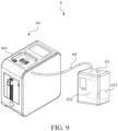
- FIG 9 illustrates a schematic diagram of a mixed gas generating device according to another embodiment of the present invention.
- the hydrogen gas generating device 60 comprises the casing 601; the gas mixing tube 65 is disposed in the casing 601 of the hydrogen gas generating device 60, and the oxygen generator 63 is disposed outside the hydrogen gas generating device 60.
- the oxygen gas generating device 63 comprises the aforementioned molecular sieve filter unit 632, the air pump 637, and an oxygen conduit 64 (the molecular sieve filter unit 632 and the air pump 637 in the figure are represented by dashed lines).
- the oxygen conduit 64 of the oxygen generator 63 passes through the casing 601 of the hydrogen generator 60 from the outside of hydrogen generator 60, and is coupled with the gas mixing tube 65 in the casing 601 of the hydrogen generator 60. Therefore, the oxygen generator 63, through the molecular sieve filter unit 632, inputs the first oxygen generated by the air pump 437 into the gas mixing tube 65 to dilute the hydrogen gas to form a mixed gas.
- the gas mixing tube and the oxygen generator both are disposed outside of the hydrogen gas generating device.
- the atomization/volatile gas mixing tank is coupled to the exit gas channel of the integrated flow channel device, and the gas mixing tube is coupled to the atomizing/volatile gas mixing tank.
- the mixed gas generating device or system comprise the oxygen generator such as molecular sieve filter to mix the hydrogen gas generated by the electrolytic cell with the oxygen gas generated by the oxygen generator to form the mixed gas for users to inhale.
- the mixed gas generating device can also be connected to an oxygen generator or an oxygen supply which is configured outside of the mixed gas generating device, such as the oxygen supply for the patient in hospital, so as to extend the use of the mixed gas generating device or system in the present invention.
- FIG 10 is a functional block diagram illustrating a mixed gas generating device connected with breathing tube and an oxygen gas generator according to an embodiment of the present invention.
- the mixed gas generating device connected with the breathing tube 1' comprises an electrolytic cell 12, a gas mixing tube 15 and the breathing tube 13'.
- the electrolytic cell 12 is configured for electrolyzing water to generate a gas comprising hydrogen or a hydrogen gas.
- the gas mixing tube 15 is coupled to the electrolytic cell 12 and the atomized/volatile gas mixing tank 16 for transporting the gas comprising hydrogen or the hydrogen gas generated by the electrolytic cell 12 to the atomized/volatile gas mixing tank 16.
- the breathing tube 13' is coupled to the gas mixing tube 15 and the oxygen gas generator 2, and is configured to receive the oxygen gas provided by the oxygen gas generator 2 and then inputs the oxygen to the gas mixing tube 15, so as to dilute the hydrogen gas or the gas comprising hydrogen in the gas mixing tube 15 to form the mixed gas.
- the oxygen gas inputted by the breathing tube 13' is called as the first oxygen hereafter.
- the mixed gas generating device connected with breathing tube 1 further comprises a hydrogen concentration detector 18.
- the hydrogen concentration detector 18 is coupled to the gas mixing tube 15 to detect a hydrogen volume concentration in the gas mixing tube 15.
- the hydrogen concentration detector 18 and the electrolytic cell 12 can be coupled to a controller 14 of the mixed gas generating device connected with breathing tube 1'.
- the controller 14 can respectively adjust the hydrogen gas generating quantity of the electrolytic cell 12 according to the hydrogen concentration detected by the hydrogen concentration detector 18, so as to dilute and adjust the hydrogen concentration of the mixed gas in the gas mixing tube 15 to be less than a predetermined value for human inhalation.
- the predetermined value can be 1%, 2%, 3%, 4%, 4.5%, 5%, 5.5%, 6%, 6.5%, 7% or 7.5%.
- the hydrogen concentration of the mixed gas is not limited to the above values but can be determined by the requirements of the user's body.
- the mixed gas generating device connected with breathing tube 1' further comprises a flow meter 19.
- the flow meter 19 is coupled to the gas mixing tube 15 to detect the flow rate value of the mixed gas in the gas mixing tube 15.
- the flow meter 19 also can be coupled to the controller 14.
- the controller 14 can adjust the quantity of the hydrogen gas generated by the electrolytic cell 12 according to the flow rate value of the mixed gas detected by the flow meter 19, so that the mixed gas generating device connected with breathing tube 1' generates the mixed gas with a predetermined flow value for the user to inhale.
- the predetermined flow value of the mixed gas can be 1.0 L/min, 2.0 L/min, 3.0 L/min, 4.0 L/min, 5.0 L/min, 6.0 L/min or above 6.0 L/min. In an embodiment, the predetermined flow value of the mixed gas can be between 3.0 L/min to 6.0 L/min.
- FIG 11a is a schematic diagram illustrating a mixed gas generating system according to an embodiment of the present invention.
- FIG 11b is a schematic diagram illustrating a mixed gas generating system according to another embodiment of the present invention.
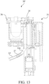
- FIG 12 is a partial schematic diagram illustrating the mixed gas generating device connected with the breathing tube 30' in FIG 11a .
- FIG 13 is a sectional diagram illustrating the mixed gas generating device 30' in FIG 11a . It should be noted that FIG 12 and FIG 13 show a part of the mixing generating device connected with the breathing tube 30', and the other parts, such as the casing or other units within the casing, are omitted from these figures for sake of brevity.
- the mixed gas generating device connected with breathing tube 30' further comprises an integrated water tank module 31, the electrolytic cell 32, the breathing tube 33', and the atomized/volatile gas mixing tank 36.
- the mixed gas generating device connected with breathing tube 30' is coupled to an oxygen generating device 38.
- the integrated water tank module 31 comprises a water tank and a gas mixing tube 35.
- One end of the breathing tube 33' is coupled to the gas mixing tube 35, and a part of breathing tube 33' extends to the outside of the casing of the mixed gas generating device connected with the breathing tube 30' to be coupled to the oxygen generating device 38, so as to input the first oxygen generated by oxygen generating device 38 through the breathing tube 33' into the gas mixing tube 35 of the mixed gas generating device connected with breathing tube 30' to dilute the hydrogen gas to form a mixed gas.
- the oxygen generating device 38 can be the equipment for hospital or medical use (as shown in FIG 11a , the oxygen equipment 38 corresponding to the hospital bed 4), the oxygen bottle or the ventilator 38' (as shown in FIG 11b ).
- the breathing tube 33' can be the oxygen tube for hospital or medical use, or the output tube of the ventilator.
- the integrated water tank module 31 further comprises a hydrogen gas port 310, an oxygen gas port 312, and a water port 314.
- the hydrogen gas port 310 coupled to the gas mixing tube 35 within the integrated water tank module 31 and the oxygen gas port 312, the water port 314 are coupled to the sink within the integrated water tank module 31.
- the hydrogen port 310, the oxygen port 312, and the water port 314 of the integrated water tank module 31 can be separately coupled to the hydrogen gas output duct 320, the oxygen gas output duct 322 and the water input duct 324, configured to respectively receive the hydrogen gas and the oxygen gas generating by the electrolytic cell 32, and output the water to supplement the electrolyzed water in the electrolytic cell 32.
- the integrated water tank module 31 comprises a supplement gas port 316 coupled to the breathing tube 33' and the gas mixing tube 35.
- the joint position between the supplement gas port 316 and the gas mixing tube 35 has an angle, and the joint position must form an arc lead angle. In practice, the angle may be a sharp angle below 90 degrees, and a better angle range in the design is between 25 and 45 degrees.
- the supplemental gas port 316 is designed with an angle so that the first oxygen in the breathing tube 33' enters into the gas mixing tube 35 to dilute the hydrogen in the gas mixing tube 35.
- the gas mixing tube within the integrated water tank module 31 is coupled to the atomized/volatile gas mixing tank 36, so that the hydrogen gas outputted from the electrolytic cell 32 enters into the gas mixing tube within the integrated water tank module 30 and then further goes into the atomized/volatile gas mixing tank 36.
- the oxygen gas (called as the second oxygen in the following) generated by the electrolytic cell 32 thought the oxygen gas output duct 322 and the oxygen port 312 is directly outputted to the integrated water tank module 31, and is discharged to the atmosphere.
- the second oxygen outputted by the electrolytic tank 32 may be mixed with little residual electrolyzed water, and the residual electrolyzed water remains in the water tank of the integrated water tank module 30 for recycling.
- the mixed gas generating device connected with the breathing tube 1' of the present invention further comprises a backfire preventer 17 disposed between the gas mixing tube 15 and the breathing tube 13'.
- the backfire preventer 37 is disposed in the breathing tube 33' and is configured to prevent gas in the gas mixing tube 15 from flowing to the breathing tube 33'.
- the backflow preventer 37 can be the flame arrester.
- the flame arrester comprises the non-return valve; therefore, the gas can pass through in one direction only.
- the backflow preventer 37 is disposed on the side of the gas mixing tube 35 and is close to the breathing tube 33'; therefore the first oxygen in the breathing tube 33' can flow to the gas mixing tube 35 through the backflow preventer 37, and the gas in the gas mixing tube 35 cannot flow into the breathing tube 33'.
- the gas mixing tube 30 may contain an inflammable gas (such as hydrogen)
- the backflow preventer 37 can prevent other gas in the gas mixing tube 35 from returning back to the breathing tube 33', to reduce or prevent the unfortunately ignited gas from spreading to the oxygen generator, thereby improving safety.
- the location of the backflow preventer in this present invention can be the location described in the aforementioned embodiment, it can also be disposed in other locations.
- the backflow preventer device is disposed between the gas mixing tube and the atomized/volatile gas mixing tank, and is disposed at the entrance of the atomized/volatile gas mixing tank, to prevent the gas in the atomized/volatile gas mixing tank from backflowing to the gas mixing tube.
- the atomized/volatile gas mixing tank is coupled to the gas mixing tube to receive the mixed gas comprising hydrogen gas and oxygen gas.
- the atomized/volatile gas mixing tank 36 generates an atomized gas mixed with the mixed gas to form a healthy gas, wherein the atomized gas is one or a combination selected from a group consist of water vapor, atomized drops, and essential oils.
- the atomized/volatile gas mixing tank 36 comprises the oscillator; the oscillator atomizes water, anatomized drops and essential oil in the atomized/volatile gas mixing tank 36 by oscillating to generate the atomized gas, and mixes the mixed gas with the atomized gas to form a health gas.
- the atomized/volatile gas mixing tank 36 can be selectively turned on or off to provide healthcare gas mixed with atomized gas or mixed gas (the hydrogen gas diluted by the second oxygen gas) for users to inhale.
- the mixed gas generating device connected with breathing tube in the aforementioned embodiments can further comprise a control panel coupled to the above-mentioned controller, thereby controlling the electrolytic cell and adjusting the hydrogen volume concentration and the output flow rate value of the mixed gas.
- FIG 14 is a schematic diagram illustrating a mixed gas generating system according to an embodiment of the present invention.
- the differences between this embodiment and the aforementioned embodiment are that the gas mixing tube 55, the backfire preventer 57, and the breathing tube 53' are coupled to the hydrogen generating device 50 from the outside of the hydrogen generating device 50, and the breathing tube 53' is coupled to the oxygen generating device 58 corresponding to the hospital bed 4.
- the hydrogen generating device 50 comprises a casing, and the casing comprises an accommodating space for accommodating the electrolytic cell, the integrated sink module and the atomized/volatile gas mixing tank mentioned above.
- the atomized/volatile gas mixing tank comprises a gas port, and the gas mixing tube 55 is coupled to the gas port of the atomized/volatile gas mixing tank disposed outside of the casing of the hydrogen generating device 50, the breathing tube 53', and the breathing mask 59 of the hydrogen generating device 50.
- the breathing tube 53' is coupled to the gas mixing tube 55 and the oxygen generating device 58, and the backfire preventer 57 is disposed in the side of the gas mixing tube 55 and close to the breathing tube 53'.
- the electrolytic cell of the hydrogen generating device 50 generates hydrogen or gas comprising hydrogen and outputs hydrogen or gas comprising hydrogen to the gas mixing tube 55 through the atomized/volatile gas mixing tank.
- the oxygen generator 58 generates the first oxygen, and the first oxygen is inputted to the gas mixing tube 55 through the breathing tube 53' to form the mixed gas. Then, the user can inhale the mixed gas through the breathing mask 59.
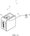
- FIG 15 is a schematic diagram illustrating a mixed gas generating system 6 according to another embodiment of the present invention.
- the internal structure of the mixed gas generating system 6 can refer to that in FIGs. 7 and 8 .
- the difference between the internal structure of the mixed gas generating system 6 with the internal structure in FIGs. 7 and 8 is that the mixed gas generating system 6 does not have the molecular sieve filtering unit and the air pump.
- the other portions in the mixed gas generating system 6 are substantially the same as those in FIGs. 7 and 8 , and then they would not be described again.
- the gas mixing tube 65 can be coupled to the exit gas channel 6042 of the integrated flow channel device 604 to receive the hydrogen gas outputted by the exit gas channel 6042.
- the gas mixing tube 65 is further coupled to the breathing tube 63' to receive the oxygen generated by oxygen generating device.
- the gas mixing tube 65 is configured to mix the hydrogen gas and the oxygen gas.
- the hydrogen gas generating device 60 comprises the casing 601; the gas mixing tube 65 is disposed in the casing 601 of the hydrogen gas generating device 60; and the oxygen generating device 68 is disposed outside the hydrogen gas generating device 60.
- the breathing tube 63' is coupled to the oxygen generating device 68 and the gas mixing tube 65 in the casing 601 of the hydrogen generator 60 by passing through the casing 601 of the hydrogen generator 60 from the outside of hydrogen generator 60. Therefore, the oxygen generated by the oxygen generating device 68 through the breathing tube 63' into the gas mixing tube 65 to dilute the hydrogen gas to form a mixed gas.
- the atomized/volatile gas mixing tank 607 of the hydrogen generator 60 can receive hydrogen and oxygen in the gas mixing tube 65, and generate the atomized gas to mixed with hydrogen and oxygen to form the mixed gas.
- the functions of the atomized/volatile gas mixing tank of this embodiment are substantially the same as the functions of the atomized/volatile gas mixing tank of the aforementioned embodiment, which are not repeated herein.
- the gas mixing tube and the oxygen generating device both are disposed outside of the hydrogen gas generating device.
- the atomized/volatile gas mixing tank is coupled to the exit gas channel of the integrated flow channel device, and the gas mixing tube is coupled to the atomizing/volatile gas mixing tank
- the mixing generating device with oxygen gas generator of the present invention is capable of generating oxygen gas by the oxygen gas generator and mixing the oxygen gas with the hydrogen gas produced by the electrolytic cell to dilute the hydrogen gas.
- the oxygen gas is mixed with the hydrogen gas to generate a mixed gas with a certain concentration of hydrogen gas for the patients with lung diseases to inhale, thus alleviating symptoms and reducing the burden on the lungs.
- the oxygen gas inputted by the oxygen gas generator makes the mixed gas have a higher oxygen concentration that is suitable for the patients with damaged lungs who requires high oxygen concentrations.
- the mixed gas produced by the device of the present invention may be mixed with the atomization gas with healing effects to form a healthy gas for human inhalation.
- the device of the present invention can prevent the backflow of gas by backfire device, thereby improving safety. Therefore, the mixed gas generating device combined with oxygen gas generator of the present invention can provide gas with multiple effects at the same time, which improves the symptoms of patients with lung diseases and also can be used for general healthcare.
Landscapes
- Health & Medical Sciences (AREA)
- Chemical & Material Sciences (AREA)
- Engineering & Computer Science (AREA)
- Organic Chemistry (AREA)
- Life Sciences & Earth Sciences (AREA)
- Emergency Medicine (AREA)
- Chemical Kinetics & Catalysis (AREA)
- Heart & Thoracic Surgery (AREA)
- Anesthesiology (AREA)
- Animal Behavior & Ethology (AREA)
- General Health & Medical Sciences (AREA)
- Public Health (AREA)
- Veterinary Medicine (AREA)
- Hematology (AREA)
- Pulmonology (AREA)
- Biomedical Technology (AREA)
- Electrochemistry (AREA)
- Materials Engineering (AREA)
- Metallurgy (AREA)
- Inorganic Chemistry (AREA)
- Analytical Chemistry (AREA)
- Geology (AREA)
- General Life Sciences & Earth Sciences (AREA)
- General Chemical & Material Sciences (AREA)
- Oil, Petroleum & Natural Gas (AREA)
- Electrolytic Production Of Non-Metals, Compounds, Apparatuses Therefor (AREA)
Abstract
Description
- The present invention relates to a mixed gas generating device combined with oxygen gas generator, and more particularly, relates to a mixed gas generating device collocating with an oxygen gas generator or connected to a breathing tube to generate a mixed gas of hydrogen gas and oxygen gas.
- People are always pay much attention to human life, so many medical technologies are developed to fight disease and keep people alive. Most of the past medical treatment methods are passive; namely, when a disease occurs, the medical treatment, such as surgery, medication and chemotherapy, radiation or recovery from chronic illness, rehabilitation and correction are given. However, in recent years, many medical experts have increasingly concentrated on preventive medical methods, such as healthy food research, genetic disease screening and disease prevention, which have taken the initiative to prevent potential future diseases. In addition, in order to extend human life, numerous anti-aging and anti-oxidant technologies have gradually developed and widely adopted by the public, including skin care products and foods/anti-oxidant drugs.
- Researches show that the body's unstable oxygen gas (O+), also known as free radicals (harmful free radicals), caused by various reasons (such as disease, diet, environment or living habits), can mix with inhaled hydrogen gas to form some of the water and be excreted by the body. Namely, by indirectly reducing the number of free radicals in the human body, the reduction of acidic physique is achieved to become healthy alkaline physique, which can resist oxidation and anti-aging, as well as achieve the effects of eliminating chronic diseases and beauty care. Moreover, by increasing the amount of hydrogen gas inhaled, the increase of the time spent on inhaling hydrogen gas (for example, inhaling hydrogen gas during sleeping time) may also efficiently improve the effect of hydrogen gas inhalation.
- In addition to the health care mentioned above, hydrogen gas is also used to provide inhalation for patients with lung diseases to relieve symptoms of lung damage. In the classical hydrogen gas generating device, the concentration of hydrogen gas in the gas produced by the electrolysis of the hydrogen gas generating device is relatively high. Therefore, the hydrogen gas generating device usually uses the method of adding air to dilute the hydrogen gas concentration before producing it for human inhalation. However, when the users are patients with lung disease, their lung functions are low and the patients need to inhale a higher concentration of oxygen gas. Although the previous hydrogen gas generating device can dilute the hydrogen gas concentration with air, it still cannot increase the oxygen gas concentration in the output gas.
- Therefore, the present invention provides a mixing generating device to solve the problems of the prior art. In one embodiment of the present invention, the mixed gas generating device comprises a hydrogen gas generating device and an oxygen gas generator. The hydrogen gas generating device further comprises an electrolytic cell and an integrated water tank module. The electrolytic cell is configured to generate a hydrogen gas and a second oxygen gas when electrolyzing water. The integrated water tank module comprises a hydrogen gas port, an oxygen gas port and an water port coupled to the electrolytic cell to receive the hydrogen gas and the second oxygen gas from the electrolytic cell and supply water to the electrolytic cell. Wherein, the hydrogen gas and the first oxygen gas are mixed to each other to form a mixed gas
- Wherein, the oxygen gas generator is configured outside of the hydrogen gas generating device, the oxygen gas generator comprises an oxygen gas conduit coupled to the hydrogen gas generating device to input the first oxygen gas into the hydrogen gas generating device, so as to mix the hydrogen gas and the first oxygen gas to form the mixed gas.
- Wherein, the oxygen gas generator comprises a molecular sieve filtering unit configured to filter an air to generate the first oxygen gas.
- Wherein, the mixed gas generating device further comprises a gas mixing tube coupled to the hydrogen gas generating device and the oxygen gas generator to receive the hydrogen gas and the first oxygen gas, so as to mix the hydrogen gas and the first oxygen gas to form the mixed gas.
- Wherein, the gas mixing tube is integrated in the integrated water tank module of the hydrogen gas generating device.
- Wherein, the gas mixing tube and the oxygen gas generator are configured outside of the hydrogen gas generating device.
- Wherein, the mixed gas generating device combined with oxygen gas generator further comprises a backfire preventer disposed between the oxygen gas generator and the gas mixing tube.
- Wherein, the hydrogen gas generating device further comprises an atomization/volatile gas mixing tank and a flame arrester. The atomization/volatile gas mixing tank is coupled to the integrated water tank module to receive the hydrogen gas from the integrated water tank module. The atomization/volatile gas mixing tank selectively generates an atomized gas to be mixed with the hydrogen gas, wherein the atomized gas is one or a combination selected from a group consisting of a water vapor, anatomized drops, and an essential oils. The flame arrester is coupled to an entrance of the atomization/volatile gas mixing tank.
- Wherein, the electrolytic cell further comprises a cathode chamber, a hydrogen gas output duct, an anode chamber, an oxygen gas output duct, a water input duct and an ion membrane. The cathode chamber is located on a first side of the electrolytic cell. The anode chamber is located on a second side of the electrolytic cell. The ion membrane is disposed between the anode chamber and the cathode chamber. The oxygen gas output duct is coupled to the oxygen gas port. The hydrogen gas output duct is coupled to the hydrogen gas port. The water input duct is coupled to the water port. The anode chamber generates the second oxygen gas and the cathode chamber generates the hydrogen gas when the electrolytic cell electrolyzes water. The oxygen gas output duct is coupled with the anode chamber and penetrates the second side to output the second oxygen gas at the second side, and the hydrogen gas output duct is coupled with the cathode chamber and extends toward the second side and penetrates the second side to output the hydrogen gas at the second side, so as to cause the hydrogen gas and the second oxygen gas to be outputted at the same side of the electrolytic cell
- Another scope of the present invention is to provide a mixed gas generating system.
- In one embodiment, the mixed gas generating system comprises a hydrogen gas generating device and an oxygen generator. The hydrogen gas generating device further comprises an electrolytic cell, an integrated flow channel module, a condensing filter, a humidification cup and a hydrogen water cup. The electrolytic cell is configured to generate a hydrogen gas when electrolyzing water. The integrated flow channel device is coupled to the electrolytic cell. The condensing filter is engaged with the integrated flow channel device and configured to filter the hydrogen gas generated by the electrolytic cell. The humidification cup is engaged with the integrated flow channel device and configured to humidify the hydrogen gas. The hydrogen water cup is engaged with the integrated flow channel device and configured to accommodate water and selectively receive the hydrogen gas. The hydrogen gas flows into the hydrogen water cup and is mixed with the water contained in the hydrogen water cup to form a hydrogen water. The oxygen gas generator is configured to generate a first oxygen gas. Wherein, the hydrogen gas and the first oxygen gas are mixed to each other to form a mixed gas
- Wherein, the oxygen gas generator is configured outside of the hydrogen gas generating device. The oxygen gas generator comprises an oxygen gas conduit coupled to the hydrogen gas generating device to input the first oxygen gas into the hydrogen gas generating device, so as to mix the hydrogen gas and the first oxygen gas to form the mixed gas.
- Wherein, the oxygen gas generator comprises a molecular sieve filtering unit configured to filter an air to generate the first oxygen gas.
- Wherein, the mixed gas generating system further comprises a gas mixing tube coupled to the hydrogen gas generating device and the oxygen gas generator to receive the hydrogen gas and the first oxygen gas, so as to mix the hydrogen gas and the first oxygen gas to form the mixed gas.
- Wherein, the gas mixing tube is integrated in the integrated water tank module of the hydrogen gas generating device.
- Wherein, the gas mixing tube and the oxygen gas generator are configured outside of the hydrogen gas generating device.
- Wherein, the mixed gas generating device further comprises a backfire preventer configured between the oxygen gas generator and the gas mixing tube.
- Wherein, the hydrogen gas generating device further comprises an atomization/volatile gas mixing tank and a flame arrester. The atomization/volatile gas mixing tank is coupled to the integrated water tank module to receive the hydrogen gas from the integrated water tank module. The atomization/volatile gas mixing tank selectively generates an atomized gas to be mixed with the hydrogen gas, wherein the atomized gas is one or a combination selected from a group consisting of a water vapor, anatomized drops, and an essential oils. The flame arrester is coupled to an entrance of the atomization/volatile gas mixing tank.
- Another scope of the present invention is to provide a mixed gas generating system.
- In one embodiment, the mixed gas generating system comprises a hydrogen gas generating device and a breathing tube. The hydrogen gas generating device further comprises an electrolytic cell and an integrated water tank module. The electrolytic cell is configured to generate a hydrogen gas and a second oxygen gas when electrolyzing water. The integrated water tank module comprises a hydrogen gas port, an oxygen gas port and a water port coupled to the electrolytic cell. The integrated water tank module is configured to receive the hydrogen gas and the second oxygen gas from the electrolytic cell and supply water to the electrolytic cell. The breathing tube is coupled to the oxygen gas generator and configured to receive a first oxygen gas generated by an oxygen generating device configured outside of the hydrogen generating device. Wherein, the hydrogen gas and the first oxygen gas are mixed to each other to form a mixed gas
- Wherein, the mixed gas generating system further comprises a gas mixing tube coupled to the breathing tube to mix the hydrogen gas and the first oxygen gas to form the mixed gas.
- Wherein, the gas mixing tube is integrated in the integrated water tank module of the hydrogen gas generating device.
- Wherein, the gas mixing tube is configured outside of the hydrogen gas generating device.
- Wherein, the mixed gas generating system further comprises a backfire preventer configured in the breathing tube.
- Wherein, the hydrogen gas generating device further comprises an atomization/volatile gas mixing tank and a flame arrester. The atomization/volatile gas mixing tank is coupled to the integrated water tank module to receive the hydrogen gas from the integrated water tank module. The atomization/volatile gas mixing tank selectively generates an atomized gas to be mixed with the hydrogen gas, wherein the atomized gas is one or a combination selected from a group consisting of a water vapor, anatomized drops, and an essential oils. The flame arrester is coupled to an entrance of the atomization/volatile gas mixing tank.
- Wherein, the electrolytic cell further comprises a cathode chamber, a hydrogen gas output duct, an anode chamber, an oxygen gas output duct, a water input duct and an ion membrane. The cathode chamber is located on a first side of the electrolytic cell. The anode chamber is located on a second side of the electrolytic cell. The ion membrane is disposed between the anode chamber and the cathode chamber. The oxygen gas output duct is coupled to the oxygen gas port. The hydrogen gas output duct is coupled to the hydrogen gas port. The water input duct is coupled to the water port. The anode chamber generates the second oxygen gas and the cathode chamber generates the hydrogen gas when the electrolytic cell electrolyzes water. The oxygen gas output duct is coupled with the anode chamber and penetrates the second side to output the second oxygen gas at the second side, and the hydrogen gas output duct is coupled with the cathode chamber and extends toward the second side and penetrates the second side to output the hydrogen gas at the second side, so as to cause the hydrogen gas and the second oxygen gas to be outputted at the same side of the electrolytic cell
- Another scope of the present invention is to provide a mixed gas generating system.
- In other embodiment, the mixed gas generating system comprises a hydrogen gas generation device and a breathing tube. The hydrogen gas generated device further comprises an electrolytic cell, an integrated flow channel device, a condensing filter, a humidification cup and a hydrogen water cup. The electrolytic cell is configured to generate a hydrogen gas when electrolyzing water. The integrated flow channel device is coupled to the electrolytic cell. The condensing filter is engaged with the integrated flow channel device. The condensing filter is configured to filter the hydrogen gas generated by the electrolytic cell. The humidification cup is engaged with the integrated flow channel device. The humidification cup is configured to humidify the hydrogen gas. The hydrogen water cup is engaged with the integrated flow channel device. The hydrogen water cup is configured to accommodate water and selectively receive the hydrogen gas. The hydrogen gas being mixed with the water contained in the hydrogen water cup to form a hydrogen water when the hydrogen gas flows into the hydrogen water cup. The breathing tube is coupled to the oxygen gas generator and configured to receive a first oxygen gas generated by an oxygen generating device which is configured outside of the hydrogen generating device. Wherein, the hydrogen gas and the first oxygen gas are mixed with each other to form a mixed gas.
- Wherein, the mixed gas generating system further comprises a gas mixing tube coupled to the hydrogen gas generating device and the oxygen gas generator to receive the hydrogen gas and the first oxygen gas, so as to mix the hydrogen gas and the first oxygen gas to form the mixed gas.
- Wherein, the gas mixing tube is integrated in the integrated water tank module of the hydrogen gas generating device.
- Wherein, the gas mixing tube is configured outside of the hydrogen gas generating device.
- Wherein, the mixed gas generating system further comprises a backfire preventer configured between the oxygen gas generator and the gas mixing tube
- Wherein, the hydrogen gas generating device further comprises an atomization/volatile gas mixing tank and a flame arrester. The atomization/volatile gas mixing tank is coupled to the integrated water tank module to receive the hydrogen gas from the integrated water tank module. The atomization/volatile gas mixing tank selectively generates an atomized gas to be mixed with the hydrogen gas, wherein the atomized gas is one or a combination selected from a group consisting of a water vapor, anatomized drops, and an essential oils. The flame arrester is coupled to an entrance of the atomization/volatile gas mixing tank
- In summary, the mixing generating device with oxygen gas generator of the present invention is capable of generating oxygen gas by the oxygen gas generator and mixing the oxygen gas with the hydrogen gas produced by the electrolytic cell to dilute the hydrogen. The oxygen gas is mixed with the hydrogen gas to generate a mixed gas with a certain concentration of hydrogen gas for the patients with lung diseases to inhale, thus alleviating symptoms and reducing the burden on the lungs. In addition, the oxygen gas inputted by the oxygen gas generator makes the mixed gas having a higher oxygen concentration that is suitable for the patients with damaged lungs who requires high oxygen concentrations. Furthermore, the mixed gas produced by the device of the present invention may be mixed with the atomization gas with healing effects to from a healthy gas for human inhalation. Moreover, the device of the present invention can prevent the backflow of gas by backfire device, thereby improving safety. Therefore, the mixed gas generating device combined with oxygen gas generator of the present invention can provide gas with multiple effects at the same time, improve the symptoms of patients with lung diseases, and also be used for general healthcare.
-
-
FIG 1 is a functional block diagram illustrating a mixing generating device with oxygen gas generator according to an embodiment of the present invention. -
FIG 2 is a partial schematic diagram illustrating a mixing generating device with oxygen gas generator according to another embodiment of the present invention. -
FIG 3 is a cross-section diagram illustrating the mixing generating device with oxygen gas generator inFIG 2 . -
FIG 4 is a sectional diagram illustrating the electrolytic cell inFIG 2 . -
FIG 5 is a schematic diagram illustrating a mixed gas generating device according to an embodiment of the present invention. -
FIG 6 is a schematic diagram illustrating a mixed gas generating device according to another embodiment of the present invention. -
FIG 7 is an explosion diagram illustrating a hydrogen gas generating device according to an embodiment of the present invention. -
FIG 8 is a schematic diagram illustrating the hydrogen gas generating device according inFIG 7 from another view angle. -
FIG 9 is a schematic diagram illustrating a mixed gas generating device according to another embodiment of the present invention. -
FIG 10 is a functional block diagram illustrating a mixed gas generating device connected with a breathing tube and an oxygen gas generator according to an embodiment of the present invention. -
FIG 11a is a schematic diagram illustrating a mixed gas generating system according to an embodiment of the present invention. -
FIG 11b is a schematic diagram illustrating a mixed gas generating system according to another embodiment of the present invention. -
FIG 12 is a partial schematic diagram illustrating the mixed gas generating device connected with the breathing tube inFIG 11a . -
FIG 13 is a sectional diagram illustrating the mixed gas generating device inFIG 11a . -
FIG 14 is a schematic diagram illustrating a mixed gas generating system according to another embodiment of the present invention. -
FIG 15 is a schematic diagram illustrating a mixed gas generating system according to another embodiment of the present invention. - For the sake of the advantages, spirits and features of the present invention can be understood more easily and clearly, the detailed descriptions and discussions will be made later by way of the embodiments and with reference of the diagrams. It is worth noting that these embodiments are merely representative embodiments of the present invention, wherein the specific methods, devices, conditions, materials and the like are not limited to the embodiments of the present invention or corresponding embodiments. Moreover, the devices in the figures are only used to express their corresponding positions and are not drawing according to their actual proportion.
- Please refer to
FIG 1. FIG.1 illustrates a functional block diagram of the mixing generating device with oxygen gas generator 1 according to an embodiment of the present invention. The mixed gas generating device combined with oxygen gas generator 1 comprising anelectrolytic cell 12, anoxygen gas generator 13, and agas mixing tube 15. Theelectrolytic cell 12 is configured for electrolyzing water to produce a hydrogen gas-containing gas or the hydrogen gas. Thegas mixing tube 15 is coupled to theelectrolytic cell 12 and the atomization/volatilegas mixing tank 16 for transporting the hydrogen gas-containing gas or hydrogen gas generated by theelectrolytic cell 12 to the atomizing gas/volatilegas mixing tank 16. Theoxygen gas generator 13 comprises amolecular sieve filter 131 to filter the air and generate the oxygen gas, which is called a first oxygen gas hereafter. Besides, theoxygen gas generator 13 is coupled to thegas mixing tube 15 to dilute the hydrogen gas by inputting the first oxygen gas into thegas mixing tube 15 to form a mixed gas. - In this embodiment, the mixed gas generating device combined with oxygen gas generator 1 further comprises a
hydrogen concentration detector 18 coupled with thegas mixing tube 15 to detect a gas volume concentration in thegas mixing tube 15. In practice, thehydrogen concentration detector 18, theelectrolytic cell 12, and theoxygen gas generator 13 can be coupled to thecontroller 14 of mixed gas generating device combined with oxygen gas generator 1. Thecontroller 14 can respectively adjust the hydrogen gas generation production quantity of theelectrolytic cell 12 and the oxygen gas production quantity of theoxygen generator 13, according to the hydrogen concentration detected by thehydrogen concentration detector 18, so as to dilute and adjust the hydrogen concentration of the mixed gas in thegas mixing tube 15 to be less than a predetermined value for human inhalation. In practice, the predetermined value can be 1% to 7.5%, but not limited to, the inhalation of hydrogen concentration depends on user's body. - In this embodiment, the mixed gas generating device combined with oxygen gas generator 1 further comprises the
flow meter 19. The flow meter19 coupled to thegas mixing tube 15 to detect the flow rate value of the mixed gas in thegas mixing tube 15. In practice, theflow meter 19 also can be coupled to thecontroller 14 as mentioned above, thecontroller 14 can respectively adjust the hydrogen gas generation volume of theelectrolytic cell 12 and the oxygen gas generation volume of theoxygen generator 13 according to the flow rate value of the mixed gas detected by the flow meter19. Furthermore, the mixed gas generating device combined with the oxygen gas generator 1 generates the mixed gas at the predetermined flow value for the user inhalation. In practice, the predetermined flow value of the mixed gas can be 1.0 L/min to 6.0 L/min or above 6.0 L/min. In an embodiment, the predetermined flow value of the mixed gas can be between 3.0 L/min to 6.0 L/min. - Please refer to
FIG.2 andFIG3 .FIG2 illustrates a partial graph of the mixing generating device with oxygen gas generator according to another embodiment of the present invention.FIG3 illustrates a cross-section of a mixing generating device with oxygen gas generator inFIG2 . Please notice that theFIG2 shows a partial of the mixing generating device with oxygen gas generator, and other parts are omitted for brevity, such as casing or other units within the casing. As shown inFIG 2 , the mixing generating device withoxygen gas generator 3 comprises the integrated water tank module30, theelectrolytic cell 32, theoxygen gas generator 34, and the atomization/volatilegas mixing tank 36. Furthermore, the integratedwater tank module 30 comprises the sink, thegas mixing tube 35, thehydrogen port 300, theoxygen port 302, and thewater port 304. Wherein, thehydrogen port 300 is coupled to thegas mixing tube 35 within the integratedwater tank module 30, and theoxygen port 302 andwater port 304 are coupled to the sink within the integratedwater tank module 30. Thehydrogen port 300, theoxygen port 302, and thewater port 304 of the integratedwater tank module 30 can be separately coupled to hydrogengas output duct 320. The oxygengas output duct 322 and thewater input duct 324 of theelectrolytic cell 32 are to respectively receive the hydrogen gas and the oxygen gas generated by theelectrolytic cell 32 to supplement the electrolyzed water in theelectrolytic cell 32. Furthermore, the second oxygen output of theelectrolytic tank 32 may be mixed with little residual electrolyzed water, and the residual electrolyzed water remains in the water tank of the integratedwater tank module 30 for recycling. - In this embodiment, the
oxygen gas generator 34 further comprises theair conduit 340, the molecularsieve oxygen generator 342, theoxygen gas conduit 344, and theair pump 347. In practice, the molecularsieve filter unit 342 can be formed by a plurality of molecular sieves in the container, such as a molecular sieve filter to filter out oxygen gas in the air. Specifically, the molecular sieves adsorb gases other than oxygen gas into the air, and only allow oxygen gas to pass through. In this embodiment, theair conduit 3 is coupled to theair pump 347 and the molecularsieve oxygen generator 342; theoxygen gas conduit 344 is coupled to the molecularsieve oxygen generator 342 and thegas mixing tube 35 of theintegrated sink module 30. Theair pump 347 sucks in air from the environment and passes the air through theair conduit 340 to the molecularsieve filter unit 342. The joint position between thesupplemental gas conduit 306 and thegas mixing tube 35 has an angle, and the joint position must form an arc lead angle. In practice, the angle may be a sharp angle below 90 degrees, and a better angle range in the design is between 25 and 45 degrees. When theair conduit 340 transmits the air sucked by theair pump 347 to the molecularsieve filter unit 342, the molecularsieve filter unit 342 filters out the first oxygen gas in the air, and outputs the first oxygen gas to thesupplemental gas conduit 306 through theoxygen gas conduit 344. Thesupplemental gas conduit 306 is designed with an angle so that the first oxygen gas in theoxygen gas conduit 344 enters into thegas mixing tube 35 to dilute the hydrogen gas in thegas mixing tube 35. The oxygen gas generator can be installed outside of the hydrogen generating device or inside it. - In this embodiment, the atomization/ volatile
gas mixing tank 36 is coupled to thegas mixing tube 35 to receive the mixed gas including the hydrogen gas and oxygen gas. The atomization/ volatilegas mixing tank 36 generates an atomizing gas to be mixed with the mixed gas to form a healthy gas, wherein the atomizing gas is one or a combination selected from a group consisting of water vapor, anatomized drops, and essential oils. In one embodiment, the atomization/volatilegas mixing tank 36 comprises an oscillator. The oscillator atomizes water, anatomized drops and essential oils in the atomization/volatilegas mixing tank 36 through oscillation to generate atomized gas, and to mix the gas with the atomized gas to form a health gas. The atomization/volatilegas mixing tank 36 can be selectively turned on or off according to users' needs to provide healthcare gas mixed with atomized gas or mixed gas (such as the hydrogen gas diluted by the second oxygen gas) for users to inhale. - Please refer to
FIG.2 andFIG4. FIG4 illustrates a cross-section of the electrolytic cell inFIG2 . In this embodiment, theelectrolytic cell 32 can be an ion membrane electrolytic cell. In practice, it is not limited to an ion membrane electrolytic cell. This present invention may also use other types of electrolytic cells. - As shown in
FIG 4 . Theelectrolytic cell 32 comprises anion membrane 321, acathode chamber 325, ananode chamber 326, a first side S1, a second side S2, a hydrogengas output duct 320, and an oxygengas output duct 322. Theion membrane 321 is disposed between the first side S1 and the second side S2; thecathode 325 is disposed between theion membrane 321 and the first side S1; and theanode 326 is disposed between theion membrane 321 and the second side S2. Wherein the area of the first side S1 and thecathode 325 located is called thecathode chamber 3201, and the area of the second side S2 and theanode electrode 326 located is called theanode chamber 3202. In order to better express the corresponding positions for thecathode chamber 3201 and theanode chamber 3202, the corresponding positions are shown by a dotted line in theFIG 3 . The hydrogengas output duct 320 extends from between theion membrane 321 and the first side S1 to the second side S2 and penetrates the second side S2, and the oxygengas output duct 322 extends between theion membrane 321 and the second side S2, and penetrates the second side S2. The cathode chamber generates the hydrogen gas and the anode chamber generates the second oxygen gas when the electrolytic cell electrolyzes water. In practice, the second oxygen gas contains oxygen, and may also contain the ozone that is not conducive to human inhalation, so the second oxygen gas and hydrogen gas are outputted separately. In this embodiment, the hydrogen gas and the second oxygen gas generated by theelectrolytic cell 32 electrolyzing water are outputted from the second side S2 ofelectrolytic cell 32 respectively through the hydrogengas output duct 320 and oxygengas output duct 322. Furthermore, theelectrolytic cell 12 may comprise thewater input duct 324 coupled to theanode chamber 3202 and penetrate the second side S2, to receive water to supplement the electrolyzed water lost after electrolysis. Therefore, thewater input duct 324, the hydrogengas output duct 320, and the oxygengas output duct 322 are disposed on the second side S2 of theelectrolytic cell 32. - In this embodiment, the hydrogen
gas output duct 320, the oxygengas output duct 322 and thewater input duct 324 are disposed on one side of theanode chamber 3202 of the electrolytic cell 32 (the second side, S2), but it is not limited to this. In one embodiment, the hydrogengas output duct 320, the oxygengas output duct 322 and thewater input duct 324 can be disposed on one side of thecathode chamber 3201 of the electrolytic cell 32 (the first side S1). - The mixing generating device with oxygen gas generator of the present invention can also include a backflow preventer device (The figure is not shown), disposed between the oxygen gas generator and the gas mixing tube, configured to prevent gas in the gas mixing tube from flowing through the oxygen generator. In practice, the backflow preventer device can be a flame arrester. The flame arrester comprises the non-return valve; therefore, the gas can pass through in one direction only. In another one of embodiment, the backflow preventer device is disposed on the gas mixing tube and is close to the oxygen generator, so that the first oxygen gas in the oxygen gas duct can flow to the gas mixing tube through the backflow preventer device, and the gas in the gas mixing tube cannot flow into the oxygen gas duct. Because the gas mixing tube may contain inflammable gas (such as hydrogen), the backflow preventer device can prevent other gas in the gas mixing tube from returning back to the oxygen gas duct, thereby preventing the gas unfortunately ignited from spreading to the oxygen generator and then improving safety. The location of the backflow preventer device is not limited to the place mentioned above. In one embodiment, the backflow preventer device can be disposed on the oxygen gas duct of the oxygen generator and close to the gas mixing tube. In another one of embodiment, the backflow preventer device is disposed between the gas mixing tube and the atomizing gas/volatile gas mixing tank, and is disposed at the entrance of the atomizing gas/volatile gas mixing tank, to prevent the gas of the atomizing gas/volatile gas mixing tank from backflowing to the gas mixing tube. In one embodiment, the flame arrester can contain at least one of a metal mesh filter and a corrugated filter. The metal mesh filter can be the stainless steel or the copper mesh with a diameter of 0.23~0.315mm and composed of multiple layers. The corrugated filter can be stainless steel, copper-nickel alloy, aluminum, and aluminum alloy which can be used to prevent the violent flame of deflagration and withstand the corresponding thermal and mechanical effects. The flame arrestor is used to block off the fire from flowing to the flame arrestor, thereby isolating the two spaces to avoid the fire spreading from one side of the flame arrester to the other side, which can cause the fire to spread through the gas flow path and make an explosion.
- In practice, the mixed gas generating device combined with an oxygen generator of the aforementioned embodiments further comprises a control panel coupled to the above-mentioned of the controller, thereby controlling the electrolytic cell and the oxygen generator and adjusting the hydrogen volume concentration and the flow rate of the mixed gas output.
- The mixing generating device with the oxygen gas generator of the present invention not only can be the aforementioned embodiments, but also can be other forms. Please refer to
FIG 5. FIG 5 illustrates a schematic diagram of a mixedgas generating device 4 according to an embodiment of the present invention. As shown inFIG 5 , the difference between this embodiment and the aforementioned embodiment is that theoxygen generator 43 is coupled tohydrogen generating device 40 from the outside of thehydrogen generating device 40. In this embodiment, thehydrogen generating device 40 comprises the casing, and the casing includes an accommodating space for the electrolytic cell, the integrated sink module, the atomization/ volatile gas mixing tank, and the gas mixing tube mentioned above. Theoxygen generator 43 is disposed on the outside of thehydrogen generating device 40, comprising the molecularsieve filtering unit 432, theair pump 437 and theoxygen gas conduit 44 mentioned above (the molecularsieve filtering unit 432 and theair pump 437 are represented by the dashed lines in figure). Theoxygen conduit 44 passes through the casing of thehydrogen generating device 40 from the outside of thehydrogen generating device 40 and coupled to the gas mixing tube located inside the casing of thehydrogen generating device 40, and the gas mixing tube is coupled to the atomization/ volatile gas mixing tank. Therefore, theoxygen generator 43, through the molecularsieve filter unit 432, inputs the first oxygen generated by theair pump 437 into the gas mixing tube to dilute the hydrogen gas to form a mixed gas. - Please refer to
FIG 6. FIG 6 illustrates a schematic diagram of a mixed gas generating device according to another embodiment of the present invention. As shown inFIG 6 , the difference between this embodiment and the aforementioned embodiment is that thegas mixing tube 55 and theoxygen generator 53 are both coupled to thehydrogen generating device 50 from the outside of thehydrogen generating device 50. In this embodiment, thehydrogen generating device 50 comprises a casing, and the casing includes an accommodating space for the electrolytic cell, the integrated sink module, and the atomization/volatile gas mixing tank mentioned above. The atomization/ volatile gas mixing tank comprises a gas port, and thegas mixing tube 55, from the outside of the casing of thehydrogen generating device 50, is coupled to the gas port of the atomization/volatile gas mixing tank, theoxygen generating device 53, and thebreathing mask 59. Theoxygen generator 53 is disposed on the outside of thehydrogen generating device 50, and can comprise the molecularsieve filtering unit 532, theair pump 537 mentioned above (the figure is represented by a dashed line). The electrolytic cell of thehydrogen generating device 50 generates hydrogen gas or hydrogen-containing gas and outputs the hydrogen gas or hydrogen-containing gas to thegas mixing tube 55 through the atomization/volatile gas mixing tank. Theoxygen generator 53, through the molecularsieve filter unit 532, inputs the first oxygen generated by theair pump 537 into thegas mixing tube 55 to form a mixed gas, so that users can inhale the mixed gas through thebreathing mask 59. - Please refer to
FIG 7 andFIG. 8 .FIG 7 illustrates an explode diagram of a hydrogen gas generating device according to embodiment of the present invention.FIG. 8 . illustrates a schematic diagram with different visual angles of a hydrogen gas generating device according inFIG.7 . As shown inFIG 7 andFIG 8 ., in the embodiment, the hydrogengas generating device 60 comprises the electrolytic cell (the figure is not shown), thewater tank 602, thehumidification cup 603, theintegrated flow channel 604, the condensingfilter devices 605,hydrogen water cup 606 and the atomization/volatilegas mixing tank 607. The electrolytic cell can be an electrolytic cell of electrode type contained in thewater tank 602, and receive the electrolyzed water from thewater tank 602 for being electrolyzed to generate hydrogen-containing gas. Thehumidification cup 603 is vertically stacked on thewater tank 602; theintegrated flow channel 604 is vertically stacked on thehumidification cup 603; and the condensingfilter devices 605 is contained in the accommodation space of theintegrated flow channel 604. - The condensing
filter devices 605 is used to filter the hydrogen gas and comprises the condensingflow channel 6051. In practice, the condensingfilter devices 605 can be implanted to theintegrated flow channel 604 and can be drawn out from the side of theintegrated flow channel 604 for replacement without disassembling the entiregas generating device 60. Thehumidification cup 603 comprises the humidification space (the figure is not shown) and the connectedspace 6031. The humidification space comprises the supplemental water and can be used to humidify the hydrogen-containing gas. The connectedspace 6031 is coupled to thewater tank 602 and theintegrated flow channel 604; therefore, the hydrogen generated by the electrolytic cell disposed in thewater tank 602 enters into the condensingflow channel 6051 of the condensingfilter device 605. Thehydrogen water cup 606 can be used to contain drinking water and input the hydrogen gas into the drinking water to form hydrogen-containing water. Theintegrated flow channel 604 comprises the entergas flow channel 6041, theexit gas channel 6042, and the gas connectingflow channel 6043. Wherein the entergas flow channel 6041 and the exitgas flow channel 6042 can be selectively coupled to thehydrogen water cup 606, and the gas connectingflow channel 6043 can be selectively coupled to the entergas flow channel 6041 and theexit gas channel 6042. The atomization/volatilegas mixing tank 607 comprises theexit gas channel 6042 to receive the hydrogen gas, and produces the atomizing gas mixing with hydrogen gas to form a health-care gas. In additional, thehumidification cup 603, the condensingfilter device 605, the atomization/volatilegas mixing tank 607, and thehydrogen water cup 606 can be engaged with or coupled to the integratedflow channel device 604. Furthermore, the hydrogengas generating device 60 also comprises the aforementioned flame arrestor (the figure is not shown), located at the entrance of the atomizing gas/volatilegas mixing tank 607. - Therefore, the hydrogen gas generated by the electrolytic cell leaves the water surface of the
water tank 602 and quickly enters into the connectedspace 6031 of thehumidification cup 603. Then the hydrogen gas flows through the connectedspace 6031 of thehumidification bottle 603, thecondensation flow channel 6051 of thecondensation filter device 605, and the entergas flow channel 6041, the exitgas flow channel 6042, and the atomization/volatilegas mixing tank 607 of theintegrated flow channel 604. Wherein, the hydrogen gas can selectively flow through thehydrogen water cup 606. However, it should be understood that the above-mentioned flow direction of the hydrogen-containing gas is one of the embodiments of the hydrogen gas generator E of the present invention, those skilled in the art can adjust the order of the components according to their needs, and it is not limited to this. - In this embodiment, the hydrogen
gas generating device 60 comprises the molecularsieve filter unit 632 and the air pump 673, and the molecularsieve filter unit 632 is used to filter the air sucked by theair pump 637 and generate oxygen. Thegas mixing tube 65 can be connected to theexit gas channel 6042 of the integratedflow channel device 604 and receive the hydrogen output from theexit gas channel 6042, and thegas mixing tube 65 can be connected to the molecularsieve filter unit 632 and theair pump 637. The functions of the molecularsieve filter unit 632 and theair pump 637 of this embodiment are substantially the same as the functions of the molecular sieve filter unit and the air pump of the aforementioned embodiment, so that it is not repeated herein. Thegas mixing tube 65 can receive the hydrogen gas output from theexit gas channel 6042, and the oxygen gas generates by the molecularsieve filter unit 632 to form a mixed gas. The atomizing/volatilegas mixing tank 607 of the hydrogengas generating device 60 can be connected to thegas mixing tube 65 and receive the mixed gas in thegas mixing tube 65, and the atomizing/volatilegas mixing tank 607 can generate the atomizing gas and the mixed gas to form the health care gas. Theoxygen generator 63 can be disposed outside thecasing 601 of the hydrogengas generating device 60, or disposed inside thecasing 601. - Please refer to
FIG 9. FIG 9 illustrates a schematic diagram of a mixed gas generating device according to another embodiment of the present invention. In this embodiment, the hydrogengas generating device 60 comprises thecasing 601; thegas mixing tube 65 is disposed in thecasing 601 of the hydrogengas generating device 60, and theoxygen generator 63 is disposed outside the hydrogengas generating device 60. The oxygengas generating device 63 comprises the aforementioned molecularsieve filter unit 632, theair pump 637, and an oxygen conduit 64 (the molecularsieve filter unit 632 and theair pump 637 in the figure are represented by dashed lines). Theoxygen conduit 64 of theoxygen generator 63 passes through thecasing 601 of thehydrogen generator 60 from the outside ofhydrogen generator 60, and is coupled with thegas mixing tube 65 in thecasing 601 of thehydrogen generator 60. Therefore, theoxygen generator 63, through the molecularsieve filter unit 632, inputs the first oxygen generated by theair pump 437 into thegas mixing tube 65 to dilute the hydrogen gas to form a mixed gas. In another embodiment, the gas mixing tube and the oxygen generator both are disposed outside of the hydrogen gas generating device. The atomization/volatile gas mixing tank is coupled to the exit gas channel of the integrated flow channel device, and the gas mixing tube is coupled to the atomizing/volatile gas mixing tank. - In the above-mentioned embodiments, the mixed gas generating device or system comprise the oxygen generator such as molecular sieve filter to mix the hydrogen gas generated by the electrolytic cell with the oxygen gas generated by the oxygen generator to form the mixed gas for users to inhale. However, the mixed gas generating device can also be connected to an oxygen generator or an oxygen supply which is configured outside of the mixed gas generating device, such as the oxygen supply for the patient in hospital, so as to extend the use of the mixed gas generating device or system in the present invention.
- Please refer to
FIG 10. FIG 10 is a functional block diagram illustrating a mixed gas generating device connected with breathing tube and an oxygen gas generator according to an embodiment of the present invention. As shown inFIG 10 , the mixed gas generating device connected with the breathing tube 1' comprises anelectrolytic cell 12, agas mixing tube 15 and the breathing tube 13'. Theelectrolytic cell 12 is configured for electrolyzing water to generate a gas comprising hydrogen or a hydrogen gas. Thegas mixing tube 15 is coupled to theelectrolytic cell 12 and the atomized/volatilegas mixing tank 16 for transporting the gas comprising hydrogen or the hydrogen gas generated by theelectrolytic cell 12 to the atomized/volatilegas mixing tank 16. The breathing tube 13' is coupled to thegas mixing tube 15 and theoxygen gas generator 2, and is configured to receive the oxygen gas provided by theoxygen gas generator 2 and then inputs the oxygen to thegas mixing tube 15, so as to dilute the hydrogen gas or the gas comprising hydrogen in thegas mixing tube 15 to form the mixed gas. The oxygen gas inputted by the breathing tube 13' is called as the first oxygen hereafter. - In this embodiment, the mixed gas generating device connected with breathing tube 1 further comprises a
hydrogen concentration detector 18. Thehydrogen concentration detector 18 is coupled to thegas mixing tube 15 to detect a hydrogen volume concentration in thegas mixing tube 15. In practice, thehydrogen concentration detector 18 and theelectrolytic cell 12 can be coupled to acontroller 14 of the mixed gas generating device connected with breathing tube 1'. Thecontroller 14 can respectively adjust the hydrogen gas generating quantity of theelectrolytic cell 12 according to the hydrogen concentration detected by thehydrogen concentration detector 18, so as to dilute and adjust the hydrogen concentration of the mixed gas in thegas mixing tube 15 to be less than a predetermined value for human inhalation. The predetermined value can be 1%, 2%, 3%, 4%, 4.5%, 5%, 5.5%, 6%, 6.5%, 7% or 7.5%. However, the hydrogen concentration of the mixed gas is not limited to the above values but can be determined by the requirements of the user's body. - In this embodiment, the mixed gas generating device connected with breathing tube 1' further comprises a
flow meter 19. Theflow meter 19 is coupled to thegas mixing tube 15 to detect the flow rate value of the mixed gas in thegas mixing tube 15. In practice, theflow meter 19 also can be coupled to thecontroller 14. Thecontroller 14 can adjust the quantity of the hydrogen gas generated by theelectrolytic cell 12 according to the flow rate value of the mixed gas detected by theflow meter 19, so that the mixed gas generating device connected with breathing tube 1' generates the mixed gas with a predetermined flow value for the user to inhale. In practice, the predetermined flow value of the mixed gas can be 1.0 L/min, 2.0 L/min, 3.0 L/min, 4.0 L/min, 5.0 L/min, 6.0 L/min or above 6.0 L/min. In an embodiment, the predetermined flow value of the mixed gas can be between 3.0 L/min to 6.0 L/min. - Please refer to
FIG 11a, FIG 11b ,FIG 12 andFIG 13 .FIG 11a is a schematic diagram illustrating a mixed gas generating system according to an embodiment of the present invention.FIG 11b is a schematic diagram illustrating a mixed gas generating system according to another embodiment of the present invention.FIG 12 is a partial schematic diagram illustrating the mixed gas generating device connected with the breathing tube 30' inFIG 11a .FIG 13 is a sectional diagram illustrating the mixed gas generating device 30' inFIG 11a . It should be noted thatFIG 12 andFIG 13 show a part of the mixing generating device connected with the breathing tube 30', and the other parts, such as the casing or other units within the casing, are omitted from these figures for sake of brevity. In this embodiment, the mixed gas generating device connected with breathing tube 30' further comprises an integratedwater tank module 31, theelectrolytic cell 32, the breathing tube 33', and the atomized/volatilegas mixing tank 36. The mixed gas generating device connected with breathing tube 30' is coupled to anoxygen generating device 38. Furthermore, the integratedwater tank module 31 comprises a water tank and agas mixing tube 35. One end of the breathing tube 33' is coupled to thegas mixing tube 35, and a part of breathing tube 33' extends to the outside of the casing of the mixed gas generating device connected with the breathing tube 30' to be coupled to theoxygen generating device 38, so as to input the first oxygen generated byoxygen generating device 38 through the breathing tube 33' into thegas mixing tube 35 of the mixed gas generating device connected with breathing tube 30' to dilute the hydrogen gas to form a mixed gas. In practice, theoxygen generating device 38 can be the equipment for hospital or medical use (as shown inFIG 11a , theoxygen equipment 38 corresponding to the hospital bed 4), the oxygen bottle or the ventilator 38' (as shown inFIG 11b ). The breathing tube 33' can be the oxygen tube for hospital or medical use, or the output tube of the ventilator. - As show in
FIG 12 andFIG 13 . The integratedwater tank module 31 further comprises ahydrogen gas port 310, anoxygen gas port 312, and awater port 314. Thehydrogen gas port 310 coupled to thegas mixing tube 35 within the integratedwater tank module 31 and theoxygen gas port 312, thewater port 314 are coupled to the sink within the integratedwater tank module 31. Thehydrogen port 310, theoxygen port 312, and thewater port 314 of the integratedwater tank module 31 can be separately coupled to the hydrogengas output duct 320, the oxygengas output duct 322 and thewater input duct 324, configured to respectively receive the hydrogen gas and the oxygen gas generating by theelectrolytic cell 32, and output the water to supplement the electrolyzed water in theelectrolytic cell 32. The detailed descriptions of the hydrogengas output duct 320, the oxygengas output duct 322 and thewater input duct 324 of theelectrolytic cell 32 will be made later. Furthermore, the integratedwater tank module 31 comprises asupplement gas port 316 coupled to the breathing tube 33' and thegas mixing tube 35. The joint position between thesupplement gas port 316 and thegas mixing tube 35 has an angle, and the joint position must form an arc lead angle. In practice, the angle may be a sharp angle below 90 degrees, and a better angle range in the design is between 25 and 45 degrees. Thesupplemental gas port 316 is designed with an angle so that the first oxygen in the breathing tube 33' enters into thegas mixing tube 35 to dilute the hydrogen in thegas mixing tube 35. - In addition, the gas mixing tube within the integrated
water tank module 31 is coupled to the atomized/volatilegas mixing tank 36, so that the hydrogen gas outputted from theelectrolytic cell 32 enters into the gas mixing tube within the integratedwater tank module 30 and then further goes into the atomized/volatilegas mixing tank 36. In practice, the oxygen gas (called as the second oxygen in the following) generated by theelectrolytic cell 32 thought the oxygengas output duct 322 and theoxygen port 312 is directly outputted to the integratedwater tank module 31, and is discharged to the atmosphere. Furthermore, the second oxygen outputted by theelectrolytic tank 32 may be mixed with little residual electrolyzed water, and the residual electrolyzed water remains in the water tank of the integratedwater tank module 30 for recycling. - Please refer to
FIG 10 andFIG 13 . The mixed gas generating device connected with the breathing tube 1' of the present invention further comprises a backfirepreventer 17 disposed between thegas mixing tube 15 and the breathing tube 13'. As shown inFIG 13 , in this embodiment, the backfirepreventer 37 is disposed in the breathing tube 33' and is configured to prevent gas in thegas mixing tube 15 from flowing to the breathing tube 33'. Thebackflow preventer 37 can be the flame arrester. The flame arrester comprises the non-return valve; therefore, the gas can pass through in one direction only. In this embodiment, thebackflow preventer 37 is disposed on the side of thegas mixing tube 35 and is close to the breathing tube 33'; therefore the first oxygen in the breathing tube 33' can flow to thegas mixing tube 35 through thebackflow preventer 37, and the gas in thegas mixing tube 35 cannot flow into the breathing tube 33'. Because thegas mixing tube 30 may contain an inflammable gas (such as hydrogen), thebackflow preventer 37 can prevent other gas in thegas mixing tube 35 from returning back to the breathing tube 33', to reduce or prevent the unfortunately ignited gas from spreading to the oxygen generator, thereby improving safety. - The location of the backflow preventer in this present invention can be the location described in the aforementioned embodiment, it can also be disposed in other locations. In another one of the embodiments, the backflow preventer device is disposed between the gas mixing tube and the atomized/volatile gas mixing tank, and is disposed at the entrance of the atomized/volatile gas mixing tank, to prevent the gas in the atomized/volatile gas mixing tank from backflowing to the gas mixing tube.
- In this embodiment, the atomized/volatile gas mixing tank is coupled to the gas mixing tube to receive the mixed gas comprising hydrogen gas and oxygen gas. The atomized/volatile
gas mixing tank 36 generates an atomized gas mixed with the mixed gas to form a healthy gas, wherein the atomized gas is one or a combination selected from a group consist of water vapor, atomized drops, and essential oils. In one embodiment, the atomized/volatilegas mixing tank 36 comprises the oscillator; the oscillator atomizes water, anatomized drops and essential oil in the atomized/volatilegas mixing tank 36 by oscillating to generate the atomized gas, and mixes the mixed gas with the atomized gas to form a health gas. According to a user's needs, the atomized/volatilegas mixing tank 36 can be selectively turned on or off to provide healthcare gas mixed with atomized gas or mixed gas (the hydrogen gas diluted by the second oxygen gas) for users to inhale. - In practice, the mixed gas generating device connected with breathing tube in the aforementioned embodiments can further comprise a control panel coupled to the above-mentioned controller, thereby controlling the electrolytic cell and adjusting the hydrogen volume concentration and the output flow rate value of the mixed gas.
- Please refer to
FIG 14. FIG 14 is a schematic diagram illustrating a mixed gas generating system according to an embodiment of the present invention. As shown inFIG 14 , the differences between this embodiment and the aforementioned embodiment are that thegas mixing tube 55, the backfirepreventer 57, and the breathing tube 53' are coupled to thehydrogen generating device 50 from the outside of thehydrogen generating device 50, and the breathing tube 53' is coupled to theoxygen generating device 58 corresponding to thehospital bed 4. In this embodiment, thehydrogen generating device 50 comprises a casing, and the casing comprises an accommodating space for accommodating the electrolytic cell, the integrated sink module and the atomized/volatile gas mixing tank mentioned above. The atomized/volatile gas mixing tank comprises a gas port, and thegas mixing tube 55 is coupled to the gas port of the atomized/volatile gas mixing tank disposed outside of the casing of thehydrogen generating device 50, the breathing tube 53', and thebreathing mask 59 of thehydrogen generating device 50. The breathing tube 53' is coupled to thegas mixing tube 55 and theoxygen generating device 58, and the backfirepreventer 57 is disposed in the side of thegas mixing tube 55 and close to the breathing tube 53'. The electrolytic cell of thehydrogen generating device 50 generates hydrogen or gas comprising hydrogen and outputs hydrogen or gas comprising hydrogen to thegas mixing tube 55 through the atomized/volatile gas mixing tank. Theoxygen generator 58 generates the first oxygen, and the first oxygen is inputted to thegas mixing tube 55 through the breathing tube 53' to form the mixed gas. Then, the user can inhale the mixed gas through thebreathing mask 59. - Please refer to
FIG 15. FIG 15 is a schematic diagram illustrating a mixedgas generating system 6 according to another embodiment of the present invention. The internal structure of the mixedgas generating system 6 can refer to that inFIGs. 7 and8 . However, the difference between the internal structure of the mixedgas generating system 6 with the internal structure inFIGs. 7 and8 is that the mixedgas generating system 6 does not have the molecular sieve filtering unit and the air pump. The other portions in the mixedgas generating system 6 are substantially the same as those inFIGs. 7 and8 , and then they would not be described again. - In this embodiment, the
gas mixing tube 65 can be coupled to theexit gas channel 6042 of the integratedflow channel device 604 to receive the hydrogen gas outputted by theexit gas channel 6042. Thegas mixing tube 65 is further coupled to the breathing tube 63' to receive the oxygen generated by oxygen generating device. Furthermore, thegas mixing tube 65 is configured to mix the hydrogen gas and the oxygen gas. In this embodiment, the hydrogengas generating device 60 comprises thecasing 601; thegas mixing tube 65 is disposed in thecasing 601 of the hydrogengas generating device 60; and theoxygen generating device 68 is disposed outside the hydrogengas generating device 60. The breathing tube 63' is coupled to theoxygen generating device 68 and thegas mixing tube 65 in thecasing 601 of thehydrogen generator 60 by passing through thecasing 601 of thehydrogen generator 60 from the outside ofhydrogen generator 60. Therefore, the oxygen generated by theoxygen generating device 68 through the breathing tube 63' into thegas mixing tube 65 to dilute the hydrogen gas to form a mixed gas. In addition, the atomized/volatilegas mixing tank 607 of thehydrogen generator 60 can receive hydrogen and oxygen in thegas mixing tube 65, and generate the atomized gas to mixed with hydrogen and oxygen to form the mixed gas. The functions of the atomized/volatile gas mixing tank of this embodiment are substantially the same as the functions of the atomized/volatile gas mixing tank of the aforementioned embodiment, which are not repeated herein. In another embodiment, the gas mixing tube and the oxygen generating device both are disposed outside of the hydrogen gas generating device. The atomized/volatile gas mixing tank is coupled to the exit gas channel of the integrated flow channel device, and the gas mixing tube is coupled to the atomizing/volatile gas mixing tank - In the summary, the mixing generating device with oxygen gas generator of the present invention is capable of generating oxygen gas by the oxygen gas generator and mixing the oxygen gas with the hydrogen gas produced by the electrolytic cell to dilute the hydrogen gas. The oxygen gas is mixed with the hydrogen gas to generate a mixed gas with a certain concentration of hydrogen gas for the patients with lung diseases to inhale, thus alleviating symptoms and reducing the burden on the lungs. In addition, the oxygen gas inputted by the oxygen gas generator makes the mixed gas have a higher oxygen concentration that is suitable for the patients with damaged lungs who requires high oxygen concentrations. Furthermore, the mixed gas produced by the device of the present invention may be mixed with the atomization gas with healing effects to form a healthy gas for human inhalation. Moreover, the device of the present invention can prevent the backflow of gas by backfire device, thereby improving safety. Therefore, the mixed gas generating device combined with oxygen gas generator of the present invention can provide gas with multiple effects at the same time, which improves the symptoms of patients with lung diseases and also can be used for general healthcare.
- With the examples and explanations mentioned above, the features and spirits of the invention are hopefully well described. More importantly, the present invention is not limited to the embodiment described herein. Those skilled in the art will readily observe that numerous modifications and alterations of the device may be made while retaining the teachings of the invention. Accordingly, the above disclosure should be construed as limited only by the metes and bounds of the appended claims.
Claims (30)
- A mixed gas generating system, comprising:a hydrogen gas generating device, further comprising:an electrolytic cell configured to produce a hydrogen gas and a second oxygen gas when electrolyzing water; andan integrated water tank module comprising a hydrogen gas port, an oxygen gas port and an water port coupled to the electrolytic cell, the integrated water tank module being configured to receive the hydrogen gas and the second oxygen gas from the electrolytic cell and supply water to the electrolytic cell; andan oxygen gas generator configured to generate a first oxygen gas;wherein the hydrogen gas and the first oxygen gas are mixed to each other to form a mixed gas.
- The mixed gas generating system of claim 1, wherein the oxygen gas generator is configured outside of the hydrogen gas generating device, the oxygen gas generator comprises an oxygen gas conduit coupled to the hydrogen gas generating device to input the first oxygen gas into the hydrogen gas generating device, so as to mix the hydrogen gas and the first oxygen gas to form the mixed gas.
- The mixed gas generating system of claim 1, wherein the oxygen gas generator comprises a molecular sieve filtering unit configured to filter an air to generate the first oxygen gas.
- The mixed gas generating system of claim 1, further comprising a gas mixing tube coupled to the hydrogen gas generating device and the oxygen gas generator to receive the hydrogen gas and the first oxygen gas, so as to mix the hydrogen gas and the first oxygen gas to form the mixed gas.
- The mixed gas generating system of claim 4, wherein the gas mixing tube is integrated in the integrated water tank module of the hydrogen gas generating device.
- The mixed gas generating system of claim 4, wherein the gas mixing tube and the oxygen gas generator are configured outside of the hydrogen gas generating device.
- The mixed gas generating system of claim 4, further comprising a backfire preventer disposed between the oxygen gas generator and the gas mixing tube.
- The mixed gas generating system of claim 1, wherein the hydrogen gas generating device further comprises an atomization/volatile gas mixing tank and a flame arrester, the atomization/volatile gas mixing tank is coupled to the integrated water tank module to receive the hydrogen gas from the integrated water tank module, the atomization/volatile gas mixing tank selectively generates an atomized gas to be mixed with the hydrogen gas, wherein the atomized gas is one or a combination selected from a group consisting of a water vapor, anatomized drops, and an essential oils, the flame arrester is coupled to an entrance of the atomization/volatile gas mixing tank.
- The mixed gas generating system of claim 1, wherein the electrolytic cell further comprises a cathode chamber, a hydrogen gas output duct, an anode chamber, an oxygen gas output duct, a water input duct and an ion membrane, the cathode chamber is located on a first side of the electrolytic cell, the anode chamber is located on a second side of the electrolytic cell, and the ion membrane is disposed between the anode chamber and the cathode chamber, the oxygen gas output duct is coupled to the oxygen gas port, the hydrogen gas output duct is coupled to the hydrogen gas port, and the water input duct is coupled to the water port, the anode chamber generates the second oxygen gas and the cathode chamber generates the hydrogen gas when the electrolytic cell electrolyzes water, the oxygen gas output duct is coupled with the anode chamber and penetrates the second side to output the second oxygen gas at the second side, the hydrogen gas output duct is coupled with the cathode chamber and extends toward the second side and penetrates the second side to output the hydrogen gas at the second side, so as to cause the hydrogen gas and the second oxygen gas to be outputted at the same side of the electrolytic cell.
- A mixed gas generating system, comprising:a hydrogen gas generating device, further comprising:an electrolytic cell configured to generate a hydrogen gas when electrolyzing water;an integrated flow channel device coupled to the electrolytic cell;a condensing filter engaged with the integrated flow channel device and configured to filter the hydrogen gas generated by the electrolytic cell;a humidification cup engaged with the integrated flow channel device and configured to humidify the hydrogen gas; anda hydrogen water cup engaged with the integrated flow channel device and configured to accommodate water and selectively receive the hydrogen gas; wherein the hydrogen gas flows into the hydrogen water cup to be mixed with the water contained in the hydrogen water cup to form a hydrogen water; andan oxygen gas generator configured to generate a first oxygen gas;wherein the hydrogen gas and the first oxygen gas are mixed to each other to form a mixed gas.
- The mixed gas generating system of claim 10, wherein the oxygen gas generator is configured outside of the hydrogen gas generating device, the oxygen gas generator comprises an oxygen gas conduit coupled to the hydrogen gas generating device to input the first oxygen gas into the hydrogen gas generating device, so as to mix the hydrogen gas and the first oxygen gas to form the mixed gas.
- The mixed gas generating system of claim 10, wherein the oxygen gas generator comprises a molecular sieve filtering unit configured to filter an air to generate the first oxygen gas.
- The mixed gas generating system of claim 10, further comprising a gas mixing tube coupled to the hydrogen gas generating device and the oxygen gas generator to receive the hydrogen gas and the first oxygen gas, so as to mix the hydrogen gas and the first oxygen gas to form the mixed gas.
- The mixed gas generating system of claim 13, wherein the gas mixing tube is integrated in the integrated water tank module of the hydrogen gas generating device.
- The mixed gas generating system of claim 13, wherein the gas mixing tube and the oxygen gas generator are configured outside of the hydrogen gas generating device.
- The mixed gas generating system of claim 13, further comprising a backfire preventer configured between the oxygen gas generator and the gas mixing tube.
- The mixed gas generating system of claim 10, wherein the hydrogen gas generating device further comprises an atomization/volatile gas mixing tank and a flame arrester, the atomization/volatile gas mixing tank is coupled to the integrated water tank module to receive the hydrogen gas from the integrated water tank module, the atomization/volatile gas mixing tank selectively generates an atomized gas to be mixed with the hydrogen gas, wherein the atomized gas is one or a combination selected from a group consisting of a water vapor, anatomized drops, and an essential oils, the flame arrester is coupled to an entrance of the atomization/volatile gas mixing tank.
- A mixed gas generating system, comprising:a hydrogen gas generating device, further comprising:an electrolytic cell configured to generate a hydrogen gas and a second oxygen gas when electrolyzing water; andan integrated water tank module comprising a hydrogen gas port, an oxygen gas port and a water port coupled to the electrolytic cell, the integrated water tank module being configured to receive the hydrogen gas and the second oxygen gas from the electrolytic cell and supply water to the electrolytic cell; anda breathing tube coupled to the oxygen gas generator and configured to receive a first oxygen gas generated by an oxygen generating device configured outside of the hydrogen generating device;wherein the hydrogen gas and the first oxygen gas are mixed to each other to form a mixed gas.
- The mixed gas generating system of claim 18, further comprising a gas mixing tube coupled to the breathing tube to mix the hydrogen gas and the first oxygen gas to form the mixed gas.
- The mixed gas generating system of claim 19, wherein the gas mixing tube is integrated in the integrated water tank module of the hydrogen gas generating device.
- The mixed gas generating system of claim 19, wherein the gas mixing tube is configured outside of the hydrogen gas generating device.
- The mixed gas generating system of claim 18, further comprising a backfire preventer configured in the breathing tube.
- The mixed gas generating system of claim 18, wherein the hydrogen gas generating device further comprises an atomization/volatile gas mixing tank and a flame arrester, the atomization/volatile gas mixing tank is coupled to the integrated water tank module to receive the hydrogen gas from the integrated water tank module, the atomization/volatile gas mixing tank selectively generates an atomized gas to be mixed with the hydrogen gas, wherein the atomized gas is one or a combination selected from a group consisting of a water vapor, anatomized drops, and an essential oils, the flame arrester is coupled to an entrance of the atomization/volatile gas mixing tank.
- The mixed gas generating system of claim 18, wherein the electrolytic cell further comprises a cathode chamber, a hydrogen gas output duct, an anode chamber, an oxygen gas output duct, a water input duct and an ion membrane, the cathode chamber is located on a first side of the electrolytic cell, the anode chamber is located on a second side of the electrolytic cell, and the ion membrane is disposed between the anode chamber and the cathode chamber, the oxygen gas output duct is coupled to the oxygen gas port, the hydrogen gas output duct is coupled to the hydrogen gas port, and the water input duct is coupled to the water port, the anode chamber generates the second oxygen gas and the cathode chamber generates the hydrogen gas when the electrolytic cell electrolyzes water, the oxygen gas output duct is coupled with the anode chamber and penetrates the second side to output the second oxygen gas at the second side, the hydrogen gas output duct is coupled with the cathode chamber and extends toward the second side and penetrates the second side to output the hydrogen gas at the second side, so as to cause the hydrogen gas and the second oxygen gas to be outputted at the same side of the electrolytic cell.
- A mixed gas generating system, comprising:a hydrogen gas generated device, further comprising:an electrolytic cell configured to generate a hydrogen gas when electrolyzing water;an integrated flow channel device coupled to the electrolytic cell;a condensing filter engaged with the integrated flow channel device, the condensing filter being configured to filter the hydrogen gas generated by the electrolytic cell;a humidification cup engaged with the integrated flow channel device, the humidification cup being configured to humidify the hydrogen gas; anda hydrogen water cup engaged with the integrated flow channel device, the hydrogen water cup being configured to accommodate water and selectively receive the hydrogen gas;the hydrogen gas being mixed with the water contained in the hydrogen water cup to form a hydrogen water when the hydrogen gas flows into the hydrogen water cup; anda breathing tube coupled to the oxygen gas generator and configured to receive a first oxygen gas generated by an oxygen generating device which is configured outside of the hydrogen generating device;wherein, the hydrogen gas and the first oxygen gas are mixed with each other to form a mixed gas.
- The mixed gas generating system claim 25, further comprising a gas mixing tube coupled to the hydrogen gas generating device and the oxygen gas generator to receive the hydrogen gas and the first oxygen gas, so as to mix the hydrogen gas and the first oxygen gas to form the mixed gas.
- The mixed gas generating system claim 25, wherein the gas mixing tube is integrated in the integrated water tank module of the hydrogen gas generating device.
- The mixed gas generating system claim 19, wherein the gas mixing tube is configured outside of the hydrogen gas generating device.
- The mixed gas generating system claim 18, further comprising a backfire preventer configured between the oxygen gas generator and the gas mixing tube.
- The mixed gas generating system claim 18, wherein the hydrogen gas generating device further comprises an atomization/volatile gas mixing tank and a flame arrester, the atomization/volatile gas mixing tank is coupled to the integrated water tank module to receive the hydrogen gas from the integrated water tank module, the atomization/volatile gas mixing tank selectively generates an atomized gas to be mixed with the hydrogen gas, wherein the atomized gas is one or a combination selected from a group consisting of a water vapor, anatomized drops, and an essential oils, the flame arrester is coupled to an entrance of the atomization/volatile gas mixing tank.
Applications Claiming Priority (3)
| Application Number | Priority Date | Filing Date | Title |
|---|---|---|---|
| CN202021464903.2U CN219430135U (en) | 2020-07-23 | 2020-07-23 | Mixed gas generating device capable of being externally connected with breathing tube and mixed gas generating system |
| CN202021468484.XU CN213911890U (en) | 2020-07-23 | 2020-07-23 | Mixed gas generating device combined with oxygen generator and mixed gas generating system |
| PCT/CN2021/107050 WO2022017311A1 (en) | 2020-07-23 | 2021-07-19 | Mixed gas generating system |
Publications (2)
| Publication Number | Publication Date |
|---|---|
| EP4186550A1 true EP4186550A1 (en) | 2023-05-31 |
| EP4186550A4 EP4186550A4 (en) | 2024-08-28 |
Family
ID=79728481
Family Applications (1)
| Application Number | Title | Priority Date | Filing Date |
|---|---|---|---|
| EP21847288.4A Pending EP4186550A4 (en) | 2020-07-23 | 2021-07-19 | Mixed gas generating system |
Country Status (4)
| Country | Link |
|---|---|
| US (1) | US20230347094A1 (en) |
| EP (1) | EP4186550A4 (en) |
| JP (1) | JP3243477U (en) |
| WO (1) | WO2022017311A1 (en) |
Families Citing this family (1)
| Publication number | Priority date | Publication date | Assignee | Title |
|---|---|---|---|---|
| CN116942985B (en) * | 2023-07-17 | 2024-03-22 | 康亦健(集团)有限公司 | Oxyhydrogen atomizer and application method thereof |
Family Cites Families (9)
| Publication number | Priority date | Publication date | Assignee | Title |
|---|---|---|---|---|
| KR100803966B1 (en) * | 2006-07-18 | 2008-02-20 | 주식회사 에너지마스타 | Apparatus of generation oxygen/hydrogen gas |
| CN102068743B (en) * | 2011-01-28 | 2013-05-08 | 重庆医科大学附属第一医院 | Hydrogen therapeutic apparatus |
| JP6461727B2 (en) * | 2015-06-23 | 2019-01-30 | 日本光電工業株式会社 | Treatment gas supply device |
| CN106435633B (en) * | 2015-08-11 | 2018-11-16 | 林信涌 | Gas generator |
| CN107773828A (en) * | 2016-08-24 | 2018-03-09 | 林信涌 | Gas generator |
| CN108531930B (en) * | 2017-03-06 | 2020-02-04 | 林信涌 | Gas generator |
| CN108220994B (en) * | 2018-02-11 | 2024-03-12 | 深圳市诺健生物科技有限公司 | Portable hydrogen-rich machine |
| CN208328128U (en) * | 2018-02-11 | 2019-01-04 | 深圳市量子氢生物技术有限公司 | A kind of portable hydrogen-rich machine |
| CN109568758A (en) * | 2018-12-19 | 2019-04-05 | 张建民 | Hydrogen-oxygen molecule suction-type therapeutic equipment |
-
2021
- 2021-07-19 WO PCT/CN2021/107050 patent/WO2022017311A1/en active Application Filing
- 2021-07-19 US US18/006,529 patent/US20230347094A1/en active Pending
- 2021-07-19 JP JP2023600007U patent/JP3243477U/en active Active
- 2021-07-19 EP EP21847288.4A patent/EP4186550A4/en active Pending
Also Published As
| Publication number | Publication date |
|---|---|
| JP3243477U (en) | 2023-08-30 |
| WO2022017311A1 (en) | 2022-01-27 |
| EP4186550A4 (en) | 2024-08-28 |
| US20230347094A1 (en) | 2023-11-02 |
Similar Documents
| Publication | Publication Date | Title |
|---|---|---|
| US11865265B2 (en) | Anti-explosion gas generator for health use | |
| US10010694B2 (en) | Gas generating system for health use | |
| US11918750B2 (en) | Healthy gas generating system | |
| US11214877B2 (en) | Gas generator | |
| TWM492749U (en) | Anti-explosion gas generator for health | |
| TWI606146B (en) | A gas generator | |
| CN213911890U (en) | Mixed gas generating device combined with oxygen generator and mixed gas generating system | |
| KR102330047B1 (en) | Water electrolysis device | |
| US11186914B2 (en) | Water electrolysis device | |
| EP4186550A1 (en) | Mixed gas generating system | |
| TWM554472U (en) | Water electrolysis device | |
| TWI681789B (en) | Gas generator | |
| CN219430135U (en) | Mixed gas generating device capable of being externally connected with breathing tube and mixed gas generating system | |
| TWI672397B (en) | Water electrolysis device |
Legal Events
| Date | Code | Title | Description |
|---|---|---|---|
| STAA | Information on the status of an ep patent application or granted ep patent |
Free format text: STATUS: THE INTERNATIONAL PUBLICATION HAS BEEN MADE |
|
| PUAI | Public reference made under article 153(3) epc to a published international application that has entered the european phase |
Free format text: ORIGINAL CODE: 0009012 |
|
| STAA | Information on the status of an ep patent application or granted ep patent |
Free format text: STATUS: REQUEST FOR EXAMINATION WAS MADE |
|
| 17P | Request for examination filed |
Effective date: 20230113 |
|
| AK | Designated contracting states |
Kind code of ref document: A1 Designated state(s): AL AT BE BG CH CY CZ DE DK EE ES FI FR GB GR HR HU IE IS IT LI LT LU LV MC MK MT NL NO PL PT RO RS SE SI SK SM TR |
|
| DAV | Request for validation of the european patent (deleted) | ||
| DAX | Request for extension of the european patent (deleted) | ||
| A4 | Supplementary search report drawn up and despatched |
Effective date: 20240729 |
|
| RIC1 | Information provided on ipc code assigned before grant |
Ipc: A61M 16/16 20060101ALI20240723BHEP Ipc: A61M 16/12 20060101AFI20240723BHEP |