EP4186544B1 - Syringe pump vibration module to reduce stopper friction - Google Patents
Syringe pump vibration module to reduce stopper friction Download PDFInfo
- Publication number
- EP4186544B1 EP4186544B1 EP22216572.2A EP22216572A EP4186544B1 EP 4186544 B1 EP4186544 B1 EP 4186544B1 EP 22216572 A EP22216572 A EP 22216572A EP 4186544 B1 EP4186544 B1 EP 4186544B1
- Authority
- EP
- European Patent Office
- Prior art keywords
- syringe
- vibrator
- plunger rod
- syringe assembly
- assembly
- Prior art date
- Legal status (The legal status is an assumption and is not a legal conclusion. Google has not performed a legal analysis and makes no representation as to the accuracy of the status listed.)
- Active
Links
- 238000001802 infusion Methods 0.000 claims description 22
- 239000012530 fluid Substances 0.000 claims description 20
- 230000033001 locomotion Effects 0.000 claims description 10
- 239000000853 adhesive Substances 0.000 claims description 5
- 230000001070 adhesive effect Effects 0.000 claims description 5
- 230000004044 response Effects 0.000 claims description 5
- 230000001939 inductive effect Effects 0.000 claims description 3
- 238000012360 testing method Methods 0.000 description 17
- 230000009467 reduction Effects 0.000 description 4
- 230000006835 compression Effects 0.000 description 3
- 238000007906 compression Methods 0.000 description 3
- 125000004122 cyclic group Chemical group 0.000 description 3
- 238000013016 damping Methods 0.000 description 2
- 230000006872 improvement Effects 0.000 description 2
- 238000012546 transfer Methods 0.000 description 2
- 230000001419 dependent effect Effects 0.000 description 1
- 230000000881 depressing effect Effects 0.000 description 1
- 238000013461 design Methods 0.000 description 1
- 238000010586 diagram Methods 0.000 description 1
- 238000005516 engineering process Methods 0.000 description 1
- 230000006870 function Effects 0.000 description 1
- 239000000314 lubricant Substances 0.000 description 1
- 238000004519 manufacturing process Methods 0.000 description 1
- 238000000034 method Methods 0.000 description 1
- 238000012986 modification Methods 0.000 description 1
- 230000004048 modification Effects 0.000 description 1
- 230000000135 prohibitive effect Effects 0.000 description 1
- 230000003068 static effect Effects 0.000 description 1
Images


Classifications
-
- A—HUMAN NECESSITIES
- A61—MEDICAL OR VETERINARY SCIENCE; HYGIENE
- A61M—DEVICES FOR INTRODUCING MEDIA INTO, OR ONTO, THE BODY; DEVICES FOR TRANSDUCING BODY MEDIA OR FOR TAKING MEDIA FROM THE BODY; DEVICES FOR PRODUCING OR ENDING SLEEP OR STUPOR
- A61M5/00—Devices for bringing media into the body in a subcutaneous, intra-vascular or intramuscular way; Accessories therefor, e.g. filling or cleaning devices, arm-rests
- A61M5/178—Syringes
-
- A—HUMAN NECESSITIES
- A61—MEDICAL OR VETERINARY SCIENCE; HYGIENE
- A61M—DEVICES FOR INTRODUCING MEDIA INTO, OR ONTO, THE BODY; DEVICES FOR TRANSDUCING BODY MEDIA OR FOR TAKING MEDIA FROM THE BODY; DEVICES FOR PRODUCING OR ENDING SLEEP OR STUPOR
- A61M5/00—Devices for bringing media into the body in a subcutaneous, intra-vascular or intramuscular way; Accessories therefor, e.g. filling or cleaning devices, arm-rests
- A61M5/14—Infusion devices, e.g. infusing by gravity; Blood infusion; Accessories therefor
- A61M5/142—Pressure infusion, e.g. using pumps
-
- A—HUMAN NECESSITIES
- A61—MEDICAL OR VETERINARY SCIENCE; HYGIENE
- A61M—DEVICES FOR INTRODUCING MEDIA INTO, OR ONTO, THE BODY; DEVICES FOR TRANSDUCING BODY MEDIA OR FOR TAKING MEDIA FROM THE BODY; DEVICES FOR PRODUCING OR ENDING SLEEP OR STUPOR
- A61M5/00—Devices for bringing media into the body in a subcutaneous, intra-vascular or intramuscular way; Accessories therefor, e.g. filling or cleaning devices, arm-rests
- A61M5/178—Syringes
- A61M5/31—Details
- A61M5/3129—Syringe barrels
-
- A—HUMAN NECESSITIES
- A61—MEDICAL OR VETERINARY SCIENCE; HYGIENE
- A61M—DEVICES FOR INTRODUCING MEDIA INTO, OR ONTO, THE BODY; DEVICES FOR TRANSDUCING BODY MEDIA OR FOR TAKING MEDIA FROM THE BODY; DEVICES FOR PRODUCING OR ENDING SLEEP OR STUPOR
- A61M5/00—Devices for bringing media into the body in a subcutaneous, intra-vascular or intramuscular way; Accessories therefor, e.g. filling or cleaning devices, arm-rests
- A61M5/178—Syringes
- A61M5/31—Details
- A61M5/315—Pistons; Piston-rods; Guiding, blocking or restricting the movement of the rod or piston; Appliances on the rod for facilitating dosing ; Dosing mechanisms
- A61M5/31511—Piston or piston-rod constructions, e.g. connection of piston with piston-rod
- A61M5/31513—Piston constructions to improve sealing or sliding
-
- A—HUMAN NECESSITIES
- A61—MEDICAL OR VETERINARY SCIENCE; HYGIENE
- A61M—DEVICES FOR INTRODUCING MEDIA INTO, OR ONTO, THE BODY; DEVICES FOR TRANSDUCING BODY MEDIA OR FOR TAKING MEDIA FROM THE BODY; DEVICES FOR PRODUCING OR ENDING SLEEP OR STUPOR
- A61M5/00—Devices for bringing media into the body in a subcutaneous, intra-vascular or intramuscular way; Accessories therefor, e.g. filling or cleaning devices, arm-rests
- A61M5/178—Syringes
- A61M5/31—Details
- A61M5/315—Pistons; Piston-rods; Guiding, blocking or restricting the movement of the rod or piston; Appliances on the rod for facilitating dosing ; Dosing mechanisms
- A61M5/31565—Administration mechanisms, i.e. constructional features, modes of administering a dose
- A61M5/31576—Constructional features or modes of drive mechanisms for piston rods
- A61M5/31578—Constructional features or modes of drive mechanisms for piston rods based on axial translation, i.e. components directly operatively associated and axially moved with plunger rod
-
- A—HUMAN NECESSITIES
- A61—MEDICAL OR VETERINARY SCIENCE; HYGIENE
- A61M—DEVICES FOR INTRODUCING MEDIA INTO, OR ONTO, THE BODY; DEVICES FOR TRANSDUCING BODY MEDIA OR FOR TAKING MEDIA FROM THE BODY; DEVICES FOR PRODUCING OR ENDING SLEEP OR STUPOR
- A61M2205/00—General characteristics of the apparatus
- A61M2205/02—General characteristics of the apparatus characterised by a particular materials
- A61M2205/0272—Electro-active or magneto-active materials
- A61M2205/0294—Piezoelectric materials
-
- A—HUMAN NECESSITIES
- A61—MEDICAL OR VETERINARY SCIENCE; HYGIENE
- A61M—DEVICES FOR INTRODUCING MEDIA INTO, OR ONTO, THE BODY; DEVICES FOR TRANSDUCING BODY MEDIA OR FOR TAKING MEDIA FROM THE BODY; DEVICES FOR PRODUCING OR ENDING SLEEP OR STUPOR
- A61M2205/00—General characteristics of the apparatus
- A61M2205/33—Controlling, regulating or measuring
- A61M2205/3327—Measuring
-
- A—HUMAN NECESSITIES
- A61—MEDICAL OR VETERINARY SCIENCE; HYGIENE
- A61M—DEVICES FOR INTRODUCING MEDIA INTO, OR ONTO, THE BODY; DEVICES FOR TRANSDUCING BODY MEDIA OR FOR TAKING MEDIA FROM THE BODY; DEVICES FOR PRODUCING OR ENDING SLEEP OR STUPOR
- A61M2205/00—General characteristics of the apparatus
- A61M2205/33—Controlling, regulating or measuring
- A61M2205/3331—Pressure; Flow
-
- A—HUMAN NECESSITIES
- A61—MEDICAL OR VETERINARY SCIENCE; HYGIENE
- A61M—DEVICES FOR INTRODUCING MEDIA INTO, OR ONTO, THE BODY; DEVICES FOR TRANSDUCING BODY MEDIA OR FOR TAKING MEDIA FROM THE BODY; DEVICES FOR PRODUCING OR ENDING SLEEP OR STUPOR
- A61M2205/00—General characteristics of the apparatus
- A61M2205/50—General characteristics of the apparatus with microprocessors or computers
- A61M2205/52—General characteristics of the apparatus with microprocessors or computers with memories providing a history of measured variating parameters of apparatus or patient
Definitions
- This invention relates generally to a syringe assembly and, more particularly, to a syringe assembly including a vibrator to reduce stopper friction during infusion.
- Stiction is the static friction that needs to be overcome to enable relative motion of stationary objects in contact. Stiction arises in syringes between the stopper and the inner wall of the syringe barrel. Syringe stiction reduction has typically been considered for ergonomic reasons, but also because it introduces a noise factor into the accuracy of conventional syringe pumps. Stiction control or reduction is typically approached in the context of lubricants or stopper design.
- syringe pumps designed to draw from the tip of a syringe, rather than depressing the plunger, the negative pressure required to draw from smaller syringe sizes can become prohibitive for any pump.
- Conventional syringe pumps are not as susceptible to stiction related problems as these "draw-from-the-tip" pumps.
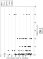
- Syringe break-loose force or stiction data illustrating the pressures required to draw from a range of syringe sizes is shown in Fig. 1 .
- a syringe assembly having the features defined within the preamble of claim 1 is for example known from US2013/242082 .
- the present invention is directed to a syringe assembly having the features defined within claim 1. Preferred embodiments defined within the dependent claims.
- the syringe assembly further comprises at least one pressure sensor configured to determine a vacuum pressure during fluid draw from the syringe by the infusion pump, wherein the vibrator is configured to vibrate based on the determined vacuum pressure.
- a vibration module attached to a syringe provides a solution to the high stiction (low pressure) problem.
- Vacuum pressure reductions for example, of about 30-70% have been demonstrated, and much better performance is expected.
- the plunger/rod system can be treated as a classical spring-mass-damper, with a cyclic driving force F d .
- x is the axial coordinate of the syringe plunger
- c is the damping coefficient
- k is the spring constant, or stiffness of the plunger rod
- m is the mass being oscillated
- F d is the cyclic driving force.
- Figs. 3A-C illustrate raw pressure traces over time for a 3 mL test syringe, a 10 mL test syringe, and a 20 mL test syringe, respectively, during an example test in which a syringe pump was plumbed to draw from the test syringes at flow rates selected to produce maximum stiction.
- a vibrator motor was affixed to the end of the plunger rod of each syringe with the motor axis perpendicular to the syringe axis.
- Each of the 3 test syringes were subjected to four test runs in an A-B-A-B-style (motor, no-motor, motor, no-motor) sequence.
- the motor When used, the motor was tuned to vibrate at a frequency substantially equal to the vibration frequency of the syringe system including the syringe and the vibration motor. Each syringe was left undisturbed for about five minutes prior to each test run. Each test run continued, and the pressure-trace was recorded up until the first "break-loose" event.
- Figs. 4A and 4B respectively summarize the minimum pressures achieved for each test run and the percent improvement for the vibration motor runs. Pressure reductions of 30-70% during fluid draw were demonstrated with the vibration motor, as well as the ability of a vibrator to break the stiction of the occasional worst-case syringe.
- a syringe assembly 10 according to preferred and non-limiting embodiments or aspects comprises a syringe 100 and a vibrator 150 configured to vibrate at at least one frequency.
- the vibrator 150 is attached to the syringe 100.
- the syringe assembly 10 may further comprise an infusion pump 170 configured to draw fluid from the syringe 100 with a negative pressure via a fluid line 180.
- the syringe 100 comprises a plunger rod 102 and a syringe barrel 104 that extends between a proximal end 104a and a distal end 104b.
- the proximal end 104a of the syringe barrel 104 includes an opening 105 configured to receive a distal end 102b of the plunger rod 102 including a stopper 107.
- the distal end 104a of the syringe barrel 104 can be connected to the infusion pump 170 via the fluid line 180 for fluid draw from the syringe 100 by the infusion pump 170.
- the distal end 104a of the syringe barrel 104 may comprise a needle cannula for fluid transfer from the syringe 100 in response to compression of the plunger rod 102.
- the vibrator 150 may include one of an eccentric weight on a motor shaft, a piezoelectric drive, and an inductive drive.
- the vibrator 150 may receive a supply of power from the infusion pump 170, another external power supply, or an internal battery (not shown).
- the vibrator can be configured to vibrate at any frequency including ultrasonic frequencies and lower frequencies.
- the vibrator 150 can include a controller including a processor and memory configured to control operation of the vibrator 150.
- the vibrator 150 can be connected to an external controller via a wired or wireless connection to control operation of the vibrator 150.
- the infusion pump 170 may include the external controller to control operation of the vibrator 150.
- the controller can control the vibrator to start or stop vibration, a frequency at which the vibrator vibrates, and/or a period or whether the vibrator 150 vibrates continuously, periodically, or based on sensor feedback as described in more detail herein. It is contemplated herein that the vibrator 150 could be rotational, linear uniaxial, or multiaxial. It is further contemplated herein that the vibrator 150 can include piezoelectric, inductive or other actuation technology.
- the vibrator 150 can be attached to the plunger rod 102.
- the vibrator 150 can be attached to the proximal end 102a of the plunger rod 102 as shown in Fig. 6 , e.g., on top of a finger flange or disc at the proximal end 102a of the plunger rod 102.
- the vibrator can be configured to impute motion to the plunger rod 102 in an axial direction of the syringe barrel 104 and/or the plunger rod 102.
- the vibrator 150 may be configured to vibrate back-and-forth in the proximal and distal directions of the syringe to impute motion in the axial direction thereof.
- the vibrator 150 can be attached between the proximal end 102a and the distal end 102b of the plunger rod 102 as shown in Fig. 7 , e.g., along or within the shaft of the plunger rod 102 and/or between cross-shaped cross sections thereof.
- the vibrator 150 can be attached to the syringe barrel 104 as shown in Fig. 8 , e.g., to an outer surface of the syringe barrel 104 between the proximal end 104a and the distal end 104b of the syringe barrel 104.
- the vibrator 150 can be configured to impute motion to the plunger rod 102 and/or the syringe barrel 104 in a direction transverse to the axial direction of the syringe barrel 104 and/or the plunger rod 102.
- the vibrator 150 when attached to the syringe barrel, the vibrator 150 may be configured to vibrate back-and-forth in a direction transverse to the axial direction of the syringe 100. It is noted herein that the vibrator 150 can be secured to any portion of the plunger rod 102, or a portion of the syringe barrel 104, as long as the vibrator is configured to impute axial motion to the syringe assembly.
- the vibrator 150 may be removably attached to the syringe 100.
- the vibrator 150 can be attached to the syringe by at least one of an adhesive connection, a mechanical connection, and a magnetic connection.
- An adhesive connection may comprise a permanent or removable and reusable adhesive pad on the vibrator 150 that forms an adhesive connection between the vibrator 150 and the syringe 100.
- a mechanical connection may comprise a band or clip configured to secure the vibrator 150 to the syringe barrel 104 or the plunger rod 102.
- a magnetic connection may comprise a magnet on each of the vibrator 150 and the syringe barrel 104 or plunger rod 102 to secure the vibrator 150 to the syringe 100.
- the vibrator 150 can be configured to vibrate at a natural frequency of a particular syringe 100, the syringe assembly 10, or a syringe system including the syringe 100 and the vibrator 150 itself. In another example, the vibrator 150 can be configured to vibrate at a plurality of different frequencies.
- the syringe assembly 10 may comprise at least one sensor 190, e.g., an accelerometer, configured to determine a natural frequency of the syringe 100, the syringe assembly 10, or a syringe system including the syringe 100 and the vibrator 150.
- the at least one sensor 190 can be connected to the vibrator 150 and/or the controller for the vibrator 150.
- the senor 190 can include an accelerometer.
- the at least one sensor 190 can be configured to determine a dynamic response of the syringe assembly 10 to the plurality of different frequencies and determine the natural frequency of the syringe assembly 10 based on the dynamic response of the syringe assembly 10 to the plurality of different frequencies. For example, when the frequency at which the vibrator 150 is vibrating is equal to the natural frequency of the syringe assembly 10, the amplitude of vibration increases exponentially, which is known as resonance.
- the at least one sensor 190 and/or the controller for the vibrator 150 can determine the frequency at which the syringe assembly 10 achieves maximum amplitude of vibration, i.e., resonance, and control the vibrator 150 to vibrate at the determined natural frequency during fluid draw from the syringe 100.
- the vibrator 150 can be configured to vibrate at the natural frequency of the syringe assembly 10 determined by the at least one sensor 190.
- the vibrator 150 has a predetermined mass configured to tune the natural frequency of the syringe assembly 10 to a preselected natural frequency.
- the mass of the vibrator 150 ca be designed to tune the natural frequency of the system including the syringe 100 and the vibrator 150 itself to a more desirable value, such as a preprogrammed vibration frequency of the vibrator 150.
- the vibrator 150 can be configured and/or controlled to vibrate one of continuously and periodically. For example, during fluid draw from the syringe 100 by the infusion pump 170, the vibrator 150 may vibrate one of continuously and periodically at the natural frequency of the syringe assembly 10.
- the syringe assembly 10 may further comprise at least one pressure sensor 195 configured to determine a vacuum pressure during fluid draw from the syringe 100 by the infusion pump 170.
- the at least one pressure sensor 195 may be located along and/or within the fluid line 180 connecting the infusion pump 170 to the syringe 100 to draw the fluid from the syringe 100.
- the at least one pressure sensor 195 can be connected to the vibrator 150 and/or the controller of the vibrator 150, and the vibrator 150 can be configured or controlled to vibrate based on the level of negative pressure determined by the at least one pressure sensor 195. For example, if the determined negative pressure violates a threshold pressure level, e.g., indicating a high stiction, the controller can control the vibrator 150 to vibrate based on the violated threshold to help reduce the stiction and the negative pressure required to continue fluid draw by the infusion pump 170. In operation, when pressure in the pump reaches a threshold pressure, the vibrator 150 may turn on thereby breaking the stiction and reducing the negative pressure in the syringe, and allow the pump to continue. In one example, the vibrator 150 may only need to be turned on periodically to keep the negative pressure above the set threshold.
- the vibrator 150 is connected to a housing of the infusion pump 170 via a line 172, such as a string or dongle, which can reduce occurrences of lost vibrators 150 in the case of a reusable vibrator 150 to be used with multiple different syringes 100 at the same infusion pump 170.
- a line 172 such as a string or dongle
Landscapes
- Health & Medical Sciences (AREA)
- Vascular Medicine (AREA)
- Engineering & Computer Science (AREA)
- Anesthesiology (AREA)
- Biomedical Technology (AREA)
- Heart & Thoracic Surgery (AREA)
- Hematology (AREA)
- Life Sciences & Earth Sciences (AREA)
- Animal Behavior & Ethology (AREA)
- General Health & Medical Sciences (AREA)
- Public Health (AREA)
- Veterinary Medicine (AREA)
- Infusion, Injection, And Reservoir Apparatuses (AREA)
- Reciprocating Pumps (AREA)
Applications Claiming Priority (3)
| Application Number | Priority Date | Filing Date | Title |
|---|---|---|---|
| US201862645423P | 2018-03-20 | 2018-03-20 | |
| EP19715310.9A EP3768354B1 (en) | 2018-03-20 | 2019-03-19 | Syringe pump vibration module to reduce stopper friction |
| PCT/US2019/022976 WO2019183098A1 (en) | 2018-03-20 | 2019-03-19 | Syringe pump vibration module to reduce stopper friction |
Related Parent Applications (1)
| Application Number | Title | Priority Date | Filing Date |
|---|---|---|---|
| EP19715310.9A Division EP3768354B1 (en) | 2018-03-20 | 2019-03-19 | Syringe pump vibration module to reduce stopper friction |
Publications (2)
| Publication Number | Publication Date |
|---|---|
| EP4186544A1 EP4186544A1 (en) | 2023-05-31 |
| EP4186544B1 true EP4186544B1 (en) | 2024-09-04 |
Family
ID=66001346
Family Applications (2)
| Application Number | Title | Priority Date | Filing Date |
|---|---|---|---|
| EP19715310.9A Active EP3768354B1 (en) | 2018-03-20 | 2019-03-19 | Syringe pump vibration module to reduce stopper friction |
| EP22216572.2A Active EP4186544B1 (en) | 2018-03-20 | 2019-03-19 | Syringe pump vibration module to reduce stopper friction |
Family Applications Before (1)
| Application Number | Title | Priority Date | Filing Date |
|---|---|---|---|
| EP19715310.9A Active EP3768354B1 (en) | 2018-03-20 | 2019-03-19 | Syringe pump vibration module to reduce stopper friction |
Country Status (6)
| Country | Link |
|---|---|
| US (1) | US12029883B2 (ja) |
| EP (2) | EP3768354B1 (ja) |
| JP (2) | JP7111824B2 (ja) |
| CN (1) | CN111902170B (ja) |
| ES (1) | ES2938221T3 (ja) |
| WO (1) | WO2019183098A1 (ja) |
Families Citing this family (1)
| Publication number | Priority date | Publication date | Assignee | Title |
|---|---|---|---|---|
| US11850395B2 (en) * | 2018-05-17 | 2023-12-26 | Carefusion 303, Inc. | Syringe driver for infusion |
Family Cites Families (14)
| Publication number | Priority date | Publication date | Assignee | Title |
|---|---|---|---|---|
| JPS5610357Y2 (ja) * | 1977-04-15 | 1981-03-09 | ||
| US5647851A (en) * | 1995-06-12 | 1997-07-15 | Pokras; Norman M. | Method and apparatus for vibrating an injection device |
| CA2422692A1 (en) | 2000-09-21 | 2002-03-28 | Elan Pharma International Limited | Reconstitution and injection system |
| WO2008086560A1 (en) * | 2007-01-15 | 2008-07-24 | John Alfred Marx | Vibrating medical device and method of performing medical procedures |
| DE102007044413A1 (de) | 2007-09-18 | 2009-03-19 | Fresenius Medical Care Deutschland Gmbh | Verfahren zur Überprüfung und/oder Überwachung der korrekten Funktion einer Zugabevorrichtung |
| US20100198141A1 (en) * | 2007-09-24 | 2010-08-05 | Laitenberger Peter G | Injection Monitor |
| JP5145177B2 (ja) * | 2008-09-12 | 2013-02-13 | 株式会社K&Y | 輸液ポンプシステム |
| CN102104674A (zh) * | 2009-12-18 | 2011-06-22 | 深圳富泰宏精密工业有限公司 | 手机及手机振动频率调整方法 |
| CA2827044A1 (en) * | 2011-02-10 | 2012-08-16 | Actuated Medical, Inc. | Medical tool with electromechanical control and feedback |
| US8913123B2 (en) * | 2012-03-19 | 2014-12-16 | West Pharmaceutical Services, Inc. | Needle shield positioning system and method |
| US20150283334A1 (en) * | 2012-10-29 | 2015-10-08 | Vibrovein Pty Ltd | Method of tuning a vibrating medical device and a connector for the same |
| US9486589B2 (en) * | 2013-11-01 | 2016-11-08 | Massachusetts Institute Of Technology | Automated method for simultaneous bubble detection and expulsion |
| US11730887B2 (en) * | 2017-10-26 | 2023-08-22 | Sanofi | Injection device with a vibration generator |
| US10940039B2 (en) * | 2017-10-31 | 2021-03-09 | Surgical Design Corporation | Automatic ultrasonic phacoemulsification control |
-
2019
- 2019-03-19 EP EP19715310.9A patent/EP3768354B1/en active Active
- 2019-03-19 JP JP2020546434A patent/JP7111824B2/ja active Active
- 2019-03-19 ES ES19715310T patent/ES2938221T3/es active Active
- 2019-03-19 CN CN201980020150.XA patent/CN111902170B/zh active Active
- 2019-03-19 EP EP22216572.2A patent/EP4186544B1/en active Active
- 2019-03-19 US US16/978,071 patent/US12029883B2/en active Active
- 2019-03-19 WO PCT/US2019/022976 patent/WO2019183098A1/en unknown
-
2022
- 2022-07-21 JP JP2022116398A patent/JP7309022B2/ja active Active
Also Published As
| Publication number | Publication date |
|---|---|
| JP7309022B2 (ja) | 2023-07-14 |
| EP3768354A1 (en) | 2021-01-27 |
| EP3768354B1 (en) | 2022-12-28 |
| JP7111824B2 (ja) | 2022-08-02 |
| CN111902170B (zh) | 2023-09-08 |
| WO2019183098A1 (en) | 2019-09-26 |
| EP4186544A1 (en) | 2023-05-31 |
| ES2938221T3 (es) | 2023-04-05 |
| US12029883B2 (en) | 2024-07-09 |
| JP2021517018A (ja) | 2021-07-15 |
| CN111902170A (zh) | 2020-11-06 |
| US20210016012A1 (en) | 2021-01-21 |
| JP2022132591A (ja) | 2022-09-08 |
Similar Documents
| Publication | Publication Date | Title |
|---|---|---|
| CN106163605B (zh) | 具有振动运动转换器的皮肤清洁装置 | |
| EP4186544B1 (en) | Syringe pump vibration module to reduce stopper friction | |
| US20110254782A1 (en) | Broadband Linear Vibrator and Mobile Terminal | |
| US9640512B2 (en) | Wire bonding apparatus comprising an oscillator mechanism | |
| US6723060B2 (en) | Vibrator | |
| CN107107353A (zh) | 线性马达及其支撑件 | |
| CN108884903A (zh) | 主动惯性阻尼器系统及方法 | |
| CN1642469A (zh) | 力反馈眼压计 | |
| KR101515136B1 (ko) | 피에조 엑츄에이터 | |
| US9745970B2 (en) | Linear piezoelectric compressor | |
| CN108895568A (zh) | 室外机及其控制方法、空调器 | |
| JP2006219986A (ja) | 振動式圧縮機 | |
| US20170211563A1 (en) | Hermetic compressor and refrigeration device | |
| KR20140103878A (ko) | 이동단말용 캔타입 압전소자 진동장치 | |
| MY195347A (en) | Acoustic transducer | |
| JPS6355349B2 (ja) | ||
| JP2016203126A (ja) | リニア振動モータ | |
| KR101652301B1 (ko) | 진동 발생장치 | |
| KR101140421B1 (ko) | 이방성 진동 가진장치 | |
| WO2024115901A1 (en) | Tattoo cartridge and device | |
| JP3475383B2 (ja) | レンズ装置 | |
| CN108130415A (zh) | 一种多振动臂通过齿轮传动耦合的振动时效装置 | |
| CN108060298A (zh) | 一种多振动臂通过连杆机构耦合的振动时效设备 | |
| JPS61224884A (ja) | 振動波モ−タ | |
| KR20050036570A (ko) | 왕복동식 압축기의 진동방지장치 |
Legal Events
| Date | Code | Title | Description |
|---|---|---|---|
| PUAI | Public reference made under article 153(3) epc to a published international application that has entered the european phase |
Free format text: ORIGINAL CODE: 0009012 |
|
| STAA | Information on the status of an ep patent application or granted ep patent |
Free format text: STATUS: THE APPLICATION HAS BEEN PUBLISHED |
|
| AC | Divisional application: reference to earlier application |
Ref document number: 3768354 Country of ref document: EP Kind code of ref document: P |
|
| AK | Designated contracting states |
Kind code of ref document: A1 Designated state(s): AL AT BE BG CH CY CZ DE DK EE ES FI FR GB GR HR HU IE IS IT LI LT LU LV MC MK MT NL NO PL PT RO RS SE SI SK SM TR |
|
| STAA | Information on the status of an ep patent application or granted ep patent |
Free format text: STATUS: REQUEST FOR EXAMINATION WAS MADE |
|
| 17P | Request for examination filed |
Effective date: 20231103 |
|
| RBV | Designated contracting states (corrected) |
Designated state(s): AL AT BE BG CH CY CZ DE DK EE ES FI FR GB GR HR HU IE IS IT LI LT LU LV MC MK MT NL NO PL PT RO RS SE SI SK SM TR |
|
| GRAP | Despatch of communication of intention to grant a patent |
Free format text: ORIGINAL CODE: EPIDOSNIGR1 |
|
| STAA | Information on the status of an ep patent application or granted ep patent |
Free format text: STATUS: GRANT OF PATENT IS INTENDED |
|
| INTG | Intention to grant announced |
Effective date: 20240403 |
|
| GRAS | Grant fee paid |
Free format text: ORIGINAL CODE: EPIDOSNIGR3 |
|
| GRAA | (expected) grant |
Free format text: ORIGINAL CODE: 0009210 |
|
| STAA | Information on the status of an ep patent application or granted ep patent |
Free format text: STATUS: THE PATENT HAS BEEN GRANTED |
|
| AC | Divisional application: reference to earlier application |
Ref document number: 3768354 Country of ref document: EP Kind code of ref document: P |
|
| AK | Designated contracting states |
Kind code of ref document: B1 Designated state(s): AL AT BE BG CH CY CZ DE DK EE ES FI FR GB GR HR HU IE IS IT LI LT LU LV MC MK MT NL NO PL PT RO RS SE SI SK SM TR |
|
| REG | Reference to a national code |
Ref country code: GB Ref legal event code: FG4D |
|
| REG | Reference to a national code |
Ref country code: CH Ref legal event code: EP |