EP4186542A1 - Multi-use drug-delivery device - Google Patents
Multi-use drug-delivery device Download PDFInfo
- Publication number
- EP4186542A1 EP4186542A1 EP23152260.8A EP23152260A EP4186542A1 EP 4186542 A1 EP4186542 A1 EP 4186542A1 EP 23152260 A EP23152260 A EP 23152260A EP 4186542 A1 EP4186542 A1 EP 4186542A1
- Authority
- EP
- European Patent Office
- Prior art keywords
- button
- springs
- needle
- actuation
- needle assembly
- Prior art date
- Legal status (The legal status is an assumption and is not a legal conclusion. Google has not performed a legal analysis and makes no representation as to the accuracy of the status listed.)
- Pending
Links
- 238000012377 drug delivery Methods 0.000 title claims abstract description 52
- 239000003814 drug Substances 0.000 claims abstract description 117
- 229940079593 drug Drugs 0.000 claims abstract description 115
- 238000002347 injection Methods 0.000 claims abstract description 67
- 239000007924 injection Substances 0.000 claims abstract description 67
- 239000012530 fluid Substances 0.000 claims abstract description 66
- 230000000712 assembly Effects 0.000 claims abstract description 46
- 238000000429 assembly Methods 0.000 claims abstract description 46
- 230000007246 mechanism Effects 0.000 claims description 67
- 238000004891 communication Methods 0.000 claims description 18
- 238000003780 insertion Methods 0.000 claims description 18
- 230000004044 response Effects 0.000 claims description 10
- 238000000034 method Methods 0.000 description 70
- 238000003825 pressing Methods 0.000 description 16
- 230000007935 neutral effect Effects 0.000 description 12
- 238000005381 potential energy Methods 0.000 description 12
- 230000037431 insertion Effects 0.000 description 11
- 230000006835 compression Effects 0.000 description 9
- 238000007906 compression Methods 0.000 description 9
- 230000000994 depressogenic effect Effects 0.000 description 8
- 230000000881 depressing effect Effects 0.000 description 7
- 238000013519 translation Methods 0.000 description 7
- 230000000903 blocking effect Effects 0.000 description 5
- 230000003993 interaction Effects 0.000 description 5
- 108010004460 Gastric Inhibitory Polypeptide Proteins 0.000 description 4
- 102100039994 Gastric inhibitory polypeptide Human genes 0.000 description 4
- 238000012546 transfer Methods 0.000 description 4
- 238000004804 winding Methods 0.000 description 4
- MASNOZXLGMXCHN-ZLPAWPGGSA-N glucagon Chemical compound C([C@@H](C(=O)N[C@H](C(=O)N[C@@H](CCC(N)=O)C(=O)N[C@@H](CC=1C2=CC=CC=C2NC=1)C(=O)N[C@@H](CC(C)C)C(=O)N[C@@H](CCSC)C(=O)N[C@@H](CC(N)=O)C(=O)N[C@@H]([C@@H](C)O)C(O)=O)C(C)C)NC(=O)[C@H](CC(O)=O)NC(=O)[C@H](CCC(N)=O)NC(=O)[C@H](C)NC(=O)[C@H](CCCNC(N)=N)NC(=O)[C@H](CCCNC(N)=N)NC(=O)[C@H](CO)NC(=O)[C@H](CC(O)=O)NC(=O)[C@H](CC(C)C)NC(=O)[C@H](CC=1C=CC(O)=CC=1)NC(=O)[C@H](CCCCN)NC(=O)[C@H](CO)NC(=O)[C@H](CC=1C=CC(O)=CC=1)NC(=O)[C@H](CC(O)=O)NC(=O)[C@H](CO)NC(=O)[C@@H](NC(=O)[C@H](CC=1C=CC=CC=1)NC(=O)[C@@H](NC(=O)CNC(=O)[C@H](CCC(N)=O)NC(=O)[C@H](CO)NC(=O)[C@@H](N)CC=1NC=NC=1)[C@@H](C)O)[C@@H](C)O)C1=CC=CC=C1 MASNOZXLGMXCHN-ZLPAWPGGSA-N 0.000 description 3
- 239000007788 liquid Substances 0.000 description 3
- 239000000463 material Substances 0.000 description 3
- 238000006243 chemical reaction Methods 0.000 description 2
- 230000003247 decreasing effect Effects 0.000 description 2
- 238000010586 diagram Methods 0.000 description 2
- 239000000446 fuel Substances 0.000 description 2
- NOESYZHRGYRDHS-UHFFFAOYSA-N insulin Chemical class N1C(=O)C(NC(=O)C(CCC(N)=O)NC(=O)C(CCC(O)=O)NC(=O)C(C(C)C)NC(=O)C(NC(=O)CN)C(C)CC)CSSCC(C(NC(CO)C(=O)NC(CC(C)C)C(=O)NC(CC=2C=CC(O)=CC=2)C(=O)NC(CCC(N)=O)C(=O)NC(CC(C)C)C(=O)NC(CCC(O)=O)C(=O)NC(CC(N)=O)C(=O)NC(CC=2C=CC(O)=CC=2)C(=O)NC(CSSCC(NC(=O)C(C(C)C)NC(=O)C(CC(C)C)NC(=O)C(CC=2C=CC(O)=CC=2)NC(=O)C(CC(C)C)NC(=O)C(C)NC(=O)C(CCC(O)=O)NC(=O)C(C(C)C)NC(=O)C(CC(C)C)NC(=O)C(CC=2NC=NC=2)NC(=O)C(CO)NC(=O)CNC2=O)C(=O)NCC(=O)NC(CCC(O)=O)C(=O)NC(CCCNC(N)=N)C(=O)NCC(=O)NC(CC=3C=CC=CC=3)C(=O)NC(CC=3C=CC=CC=3)C(=O)NC(CC=3C=CC(O)=CC=3)C(=O)NC(C(C)O)C(=O)N3C(CCC3)C(=O)NC(CCCCN)C(=O)NC(C)C(O)=O)C(=O)NC(CC(N)=O)C(O)=O)=O)NC(=O)C(C(C)CC)NC(=O)C(CO)NC(=O)C(C(C)O)NC(=O)C1CSSCC2NC(=O)C(CC(C)C)NC(=O)C(NC(=O)C(CCC(N)=O)NC(=O)C(CC(N)=O)NC(=O)C(NC(=O)C(N)CC=1C=CC=CC=1)C(C)C)CC1=CN=CN1 NOESYZHRGYRDHS-UHFFFAOYSA-N 0.000 description 2
- PXZWGQLGAKCNKD-DPNMSELWSA-N molport-023-276-326 Chemical class C([C@@H](C(=O)N[C@H](C(=O)N[C@@H](CCC(N)=O)C(=O)N[C@@H](CC=1C2=CC=CC=C2NC=1)C(=O)N[C@@H](CC(C)C)C(=O)N[C@@H](CCSC)C(=O)N[C@@H](CC(N)=O)C(=O)N[C@H](C(=O)N[C@@H](CCCCN)C(=O)N[C@@H](CCCNC(N)=N)C(=O)N[C@@H](CC(N)=O)C(=O)N[C@@H](CCCCN)C(=O)N[C@@H](CC(N)=O)C(=O)N[C@@H](CC(N)=O)C(=O)N[C@@H]([C@@H](C)CC)C(=O)N[C@@H](C)C(O)=O)[C@@H](C)O)C(C)C)NC(=O)[C@H](CC(O)=O)NC(=O)[C@H](CCC(N)=O)NC(=O)[C@H](C)NC(=O)[C@H](CCCNC(N)=N)NC(=O)[C@H](CCCNC(N)=N)NC(=O)[C@H](CO)NC(=O)[C@H](CC(O)=O)NC(=O)[C@H](CC(C)C)NC(=O)[C@H](CC=1C=CC(O)=CC=1)NC(=O)[C@H](CCCCN)NC(=O)[C@H](CO)NC(=O)[C@H](CC=1C=CC(O)=CC=1)NC(=O)[C@H](CC(O)=O)NC(=O)[C@H](CO)NC(=O)[C@@H](NC(=O)[C@H](CC=1C=CC=CC=1)NC(=O)[C@@H](NC(=O)CNC(=O)[C@H](CCC(N)=O)NC(=O)[C@H](CO)NC(=O)[C@@H](N)CC=1NC=NC=1)[C@@H](C)O)[C@@H](C)O)C1=CC=CC=C1 PXZWGQLGAKCNKD-DPNMSELWSA-N 0.000 description 2
- 238000005086 pumping Methods 0.000 description 2
- 229940124597 therapeutic agent Drugs 0.000 description 2
- 229920000089 Cyclic olefin copolymer Polymers 0.000 description 1
- 239000004713 Cyclic olefin copolymer Substances 0.000 description 1
- 102000051325 Glucagon Human genes 0.000 description 1
- 108060003199 Glucagon Proteins 0.000 description 1
- 229940089838 Glucagon-like peptide 1 receptor agonist Drugs 0.000 description 1
- 108090001061 Insulin Proteins 0.000 description 1
- 102000004877 Insulin Human genes 0.000 description 1
- 108010057186 Insulin Glargine Proteins 0.000 description 1
- 108010065920 Insulin Lispro Proteins 0.000 description 1
- COCFEDIXXNGUNL-RFKWWTKHSA-N Insulin glargine Chemical compound C([C@@H](C(=O)N[C@@H](CC(C)C)C(=O)N[C@H]1CSSC[C@H]2C(=O)N[C@H](C(=O)N[C@@H](CO)C(=O)N[C@H](C(=O)N[C@H](C(N[C@@H](CO)C(=O)N[C@@H](CC(C)C)C(=O)N[C@@H](CC=3C=CC(O)=CC=3)C(=O)N[C@@H](CCC(N)=O)C(=O)N[C@@H](CC(C)C)C(=O)N[C@@H](CCC(O)=O)C(=O)N[C@@H](CC(N)=O)C(=O)N[C@@H](CC=3C=CC(O)=CC=3)C(=O)N[C@@H](CSSC[C@H](NC(=O)[C@H](C(C)C)NC(=O)[C@H](CC(C)C)NC(=O)[C@H](CC=3C=CC(O)=CC=3)NC(=O)[C@H](CC(C)C)NC(=O)[C@H](C)NC(=O)[C@H](CCC(O)=O)NC(=O)[C@H](C(C)C)NC(=O)[C@H](CC(C)C)NC(=O)[C@H](CC=3NC=NC=3)NC(=O)[C@H](CO)NC(=O)CNC1=O)C(=O)NCC(=O)N[C@@H](CCC(O)=O)C(=O)N[C@@H](CCCNC(N)=N)C(=O)NCC(=O)N[C@@H](CC=1C=CC=CC=1)C(=O)N[C@@H](CC=1C=CC=CC=1)C(=O)N[C@@H](CC=1C=CC(O)=CC=1)C(=O)N[C@@H]([C@@H](C)O)C(=O)N1[C@@H](CCC1)C(=O)N[C@@H](CCCCN)C(=O)N[C@@H]([C@@H](C)O)C(=O)N[C@@H](CCCNC(N)=N)C(=O)N[C@@H](CCCNC(N)=N)C(O)=O)C(=O)NCC(O)=O)=O)CSSC[C@@H](C(N2)=O)NC(=O)[C@H](CCC(N)=O)NC(=O)[C@H](CCC(O)=O)NC(=O)[C@H](C(C)C)NC(=O)[C@@H](NC(=O)CN)[C@@H](C)CC)[C@@H](C)CC)[C@@H](C)O)NC(=O)[C@H](CCC(N)=O)NC(=O)[C@H](CC(N)=O)NC(=O)[C@@H](NC(=O)[C@@H](N)CC=1C=CC=CC=1)C(C)C)C1=CN=CN1 COCFEDIXXNGUNL-RFKWWTKHSA-N 0.000 description 1
- YSDQQAXHVYUZIW-QCIJIYAXSA-N Liraglutide Chemical compound C([C@@H](C(=O)N[C@@H](CC(C)C)C(=O)N[C@@H](CCC(O)=O)C(=O)NCC(=O)N[C@@H](CCC(N)=O)C(=O)N[C@@H](C)C(=O)N[C@@H](C)C(=O)N[C@@H](CCCCNC(=O)CC[C@H](NC(=O)CCCCCCCCCCCCCCC)C(O)=O)C(=O)N[C@@H](CCC(O)=O)C(=O)N[C@@H](CC=1C=CC=CC=1)C(=O)N[C@@H]([C@@H](C)CC)C(=O)N[C@@H](C)C(=O)N[C@@H](CC=1C2=CC=CC=C2NC=1)C(=O)N[C@@H](CC(C)C)C(=O)N[C@@H](C(C)C)C(=O)N[C@@H](CCCNC(N)=N)C(=O)NCC(=O)N[C@@H](CCCNC(N)=N)C(=O)NCC(O)=O)NC(=O)[C@H](CO)NC(=O)[C@H](CO)NC(=O)[C@@H](NC(=O)[C@H](CC(O)=O)NC(=O)[C@H](CO)NC(=O)[C@@H](NC(=O)[C@H](CC=1C=CC=CC=1)NC(=O)[C@@H](NC(=O)CNC(=O)[C@H](CCC(O)=O)NC(=O)[C@H](C)NC(=O)[C@@H](N)CC=1NC=NC=1)[C@@H](C)O)[C@@H](C)O)C(C)C)C1=CC=C(O)C=C1 YSDQQAXHVYUZIW-QCIJIYAXSA-N 0.000 description 1
- 108010019598 Liraglutide Proteins 0.000 description 1
- 239000004743 Polypropylene Substances 0.000 description 1
- 230000006978 adaptation Effects 0.000 description 1
- 150000001336 alkenes Chemical class 0.000 description 1
- 238000002485 combustion reaction Methods 0.000 description 1
- 230000008878 coupling Effects 0.000 description 1
- 238000010168 coupling process Methods 0.000 description 1
- 238000005859 coupling reaction Methods 0.000 description 1
- 230000007423 decrease Effects 0.000 description 1
- 229960005175 dulaglutide Drugs 0.000 description 1
- 108010005794 dulaglutide Proteins 0.000 description 1
- 229960004666 glucagon Drugs 0.000 description 1
- WNRQPCUGRUFHED-DETKDSODSA-N humalog Chemical compound C([C@H](NC(=O)[C@H](CC(C)C)NC(=O)[C@H](CO)NC(=O)[C@H](CS)NC(=O)[C@H]([C@@H](C)CC)NC(=O)[C@H](CO)NC(=O)[C@H]([C@@H](C)O)NC(=O)[C@H](CS)NC(=O)[C@H](CS)NC(=O)[C@H](CCC(N)=O)NC(=O)[C@H](CCC(O)=O)NC(=O)[C@H](C(C)C)NC(=O)[C@@H](NC(=O)CN)[C@@H](C)CC)C(=O)N[C@@H](CCC(N)=O)C(=O)N[C@@H](CC(C)C)C(=O)N[C@@H](CCC(O)=O)C(=O)N[C@@H](CC(N)=O)C(=O)N[C@@H](CC=1C=CC(O)=CC=1)C(=O)N[C@@H](CS)C(=O)N[C@@H](CC(N)=O)C(O)=O)C1=CC=C(O)C=C1.C([C@@H](C(=O)N[C@@H](CC(C)C)C(=O)N[C@H](C(=O)N[C@@H](CCC(O)=O)C(=O)N[C@@H](C)C(=O)N[C@@H](CC(C)C)C(=O)N[C@@H](CC=1C=CC(O)=CC=1)C(=O)N[C@@H](CC(C)C)C(=O)N[C@@H](C(C)C)C(=O)N[C@@H](CS)C(=O)NCC(=O)N[C@@H](CCC(O)=O)C(=O)N[C@@H](CCCNC(N)=N)C(=O)NCC(=O)N[C@@H](CC=1C=CC=CC=1)C(=O)N[C@@H](CC=1C=CC=CC=1)C(=O)N[C@@H](CC=1C=CC(O)=CC=1)C(=O)N[C@@H]([C@@H](C)O)C(=O)N[C@@H](CCCCN)C(=O)N1[C@@H](CCC1)C(=O)N[C@@H]([C@@H](C)O)C(O)=O)C(C)C)NC(=O)[C@H](CO)NC(=O)CNC(=O)[C@H](CS)NC(=O)[C@H](CC(C)C)NC(=O)[C@H](CC=1NC=NC=1)NC(=O)[C@H](CCC(N)=O)NC(=O)[C@H](CC(N)=O)NC(=O)[C@@H](NC(=O)[C@@H](N)CC=1C=CC=CC=1)C(C)C)C1=CN=CN1 WNRQPCUGRUFHED-DETKDSODSA-N 0.000 description 1
- 239000004026 insulin derivative Substances 0.000 description 1
- 229960002869 insulin glargine Drugs 0.000 description 1
- 229960002068 insulin lispro Drugs 0.000 description 1
- 238000007918 intramuscular administration Methods 0.000 description 1
- 230000000670 limiting effect Effects 0.000 description 1
- 229960002701 liraglutide Drugs 0.000 description 1
- 230000007774 longterm Effects 0.000 description 1
- 239000000314 lubricant Substances 0.000 description 1
- JRZJOMJEPLMPRA-UHFFFAOYSA-N olefin Natural products CCCCCCCC=C JRZJOMJEPLMPRA-UHFFFAOYSA-N 0.000 description 1
- 230000037361 pathway Effects 0.000 description 1
- 230000002572 peristaltic effect Effects 0.000 description 1
- 239000000546 pharmaceutical excipient Substances 0.000 description 1
- 239000004033 plastic Substances 0.000 description 1
- -1 polypropylene Polymers 0.000 description 1
- 229920001155 polypropylene Polymers 0.000 description 1
- 238000002360 preparation method Methods 0.000 description 1
- 230000002829 reductive effect Effects 0.000 description 1
- 229920002545 silicone oil Polymers 0.000 description 1
- 238000007920 subcutaneous administration Methods 0.000 description 1
- 239000000126 substance Substances 0.000 description 1
- 230000001225 therapeutic effect Effects 0.000 description 1
Images


Classifications
-
- A—HUMAN NECESSITIES
- A61—MEDICAL OR VETERINARY SCIENCE; HYGIENE
- A61M—DEVICES FOR INTRODUCING MEDIA INTO, OR ONTO, THE BODY; DEVICES FOR TRANSDUCING BODY MEDIA OR FOR TAKING MEDIA FROM THE BODY; DEVICES FOR PRODUCING OR ENDING SLEEP OR STUPOR
- A61M5/00—Devices for bringing media into the body in a subcutaneous, intra-vascular or intramuscular way; Accessories therefor, e.g. filling or cleaning devices, arm-rests
- A61M5/14—Infusion devices, e.g. infusing by gravity; Blood infusion; Accessories therefor
- A61M5/158—Needles for infusions; Accessories therefor, e.g. for inserting infusion needles, or for holding them on the body
-
- A—HUMAN NECESSITIES
- A61—MEDICAL OR VETERINARY SCIENCE; HYGIENE
- A61M—DEVICES FOR INTRODUCING MEDIA INTO, OR ONTO, THE BODY; DEVICES FOR TRANSDUCING BODY MEDIA OR FOR TAKING MEDIA FROM THE BODY; DEVICES FOR PRODUCING OR ENDING SLEEP OR STUPOR
- A61M5/00—Devices for bringing media into the body in a subcutaneous, intra-vascular or intramuscular way; Accessories therefor, e.g. filling or cleaning devices, arm-rests
- A61M5/14—Infusion devices, e.g. infusing by gravity; Blood infusion; Accessories therefor
- A61M5/142—Pressure infusion, e.g. using pumps
- A61M5/14244—Pressure infusion, e.g. using pumps adapted to be carried by the patient, e.g. portable on the body
- A61M5/14248—Pressure infusion, e.g. using pumps adapted to be carried by the patient, e.g. portable on the body of the skin patch type
-
- A—HUMAN NECESSITIES
- A61—MEDICAL OR VETERINARY SCIENCE; HYGIENE
- A61M—DEVICES FOR INTRODUCING MEDIA INTO, OR ONTO, THE BODY; DEVICES FOR TRANSDUCING BODY MEDIA OR FOR TAKING MEDIA FROM THE BODY; DEVICES FOR PRODUCING OR ENDING SLEEP OR STUPOR
- A61M5/00—Devices for bringing media into the body in a subcutaneous, intra-vascular or intramuscular way; Accessories therefor, e.g. filling or cleaning devices, arm-rests
- A61M5/14—Infusion devices, e.g. infusing by gravity; Blood infusion; Accessories therefor
- A61M5/142—Pressure infusion, e.g. using pumps
-
- A—HUMAN NECESSITIES
- A61—MEDICAL OR VETERINARY SCIENCE; HYGIENE
- A61M—DEVICES FOR INTRODUCING MEDIA INTO, OR ONTO, THE BODY; DEVICES FOR TRANSDUCING BODY MEDIA OR FOR TAKING MEDIA FROM THE BODY; DEVICES FOR PRODUCING OR ENDING SLEEP OR STUPOR
- A61M5/00—Devices for bringing media into the body in a subcutaneous, intra-vascular or intramuscular way; Accessories therefor, e.g. filling or cleaning devices, arm-rests
- A61M5/14—Infusion devices, e.g. infusing by gravity; Blood infusion; Accessories therefor
- A61M5/168—Means for controlling media flow to the body or for metering media to the body, e.g. drip meters, counters ; Monitoring media flow to the body
-
- A—HUMAN NECESSITIES
- A61—MEDICAL OR VETERINARY SCIENCE; HYGIENE
- A61M—DEVICES FOR INTRODUCING MEDIA INTO, OR ONTO, THE BODY; DEVICES FOR TRANSDUCING BODY MEDIA OR FOR TAKING MEDIA FROM THE BODY; DEVICES FOR PRODUCING OR ENDING SLEEP OR STUPOR
- A61M5/00—Devices for bringing media into the body in a subcutaneous, intra-vascular or intramuscular way; Accessories therefor, e.g. filling or cleaning devices, arm-rests
- A61M5/14—Infusion devices, e.g. infusing by gravity; Blood infusion; Accessories therefor
- A61M5/142—Pressure infusion, e.g. using pumps
- A61M5/14244—Pressure infusion, e.g. using pumps adapted to be carried by the patient, e.g. portable on the body
- A61M5/14248—Pressure infusion, e.g. using pumps adapted to be carried by the patient, e.g. portable on the body of the skin patch type
- A61M2005/14252—Pressure infusion, e.g. using pumps adapted to be carried by the patient, e.g. portable on the body of the skin patch type with needle insertion means
- A61M2005/14256—Pressure infusion, e.g. using pumps adapted to be carried by the patient, e.g. portable on the body of the skin patch type with needle insertion means with means for preventing access to the needle after use
-
- A—HUMAN NECESSITIES
- A61—MEDICAL OR VETERINARY SCIENCE; HYGIENE
- A61M—DEVICES FOR INTRODUCING MEDIA INTO, OR ONTO, THE BODY; DEVICES FOR TRANSDUCING BODY MEDIA OR FOR TAKING MEDIA FROM THE BODY; DEVICES FOR PRODUCING OR ENDING SLEEP OR STUPOR
- A61M5/00—Devices for bringing media into the body in a subcutaneous, intra-vascular or intramuscular way; Accessories therefor, e.g. filling or cleaning devices, arm-rests
- A61M5/14—Infusion devices, e.g. infusing by gravity; Blood infusion; Accessories therefor
- A61M5/142—Pressure infusion, e.g. using pumps
- A61M5/145—Pressure infusion, e.g. using pumps using pressurised reservoirs, e.g. pressurised by means of pistons
- A61M2005/14506—Pressure infusion, e.g. using pumps using pressurised reservoirs, e.g. pressurised by means of pistons mechanically driven, e.g. spring or clockwork
-
- A—HUMAN NECESSITIES
- A61—MEDICAL OR VETERINARY SCIENCE; HYGIENE
- A61M—DEVICES FOR INTRODUCING MEDIA INTO, OR ONTO, THE BODY; DEVICES FOR TRANSDUCING BODY MEDIA OR FOR TAKING MEDIA FROM THE BODY; DEVICES FOR PRODUCING OR ENDING SLEEP OR STUPOR
- A61M5/00—Devices for bringing media into the body in a subcutaneous, intra-vascular or intramuscular way; Accessories therefor, e.g. filling or cleaning devices, arm-rests
- A61M5/14—Infusion devices, e.g. infusing by gravity; Blood infusion; Accessories therefor
- A61M5/158—Needles for infusions; Accessories therefor, e.g. for inserting infusion needles, or for holding them on the body
- A61M2005/1585—Needle inserters
Abstract
Description
- The present disclosure relates to devices and methods for delivering drugs. More particularly, the present disclosure relates to a multi-use drug-delivery device.
- Some drug-delivery devices, such as autoinjectors, store potential energy in compression springs which are released at the time of device actuation. This stored energy is used to drive various functions of such drug-delivery devices, such as needle insertion into the patient and ejection of fluid from a drug reservoir. However, long-term potential energy storage in springs can be problematic because resultant forces from compressed springs can cause device material deformation over the shelf life of a device. Furthermore, basic physics and material properties require that springs adequate for storing sufficient potential energy to drive the previously-mentioned functions in a drug-delivery device over the shelf life of the device be of a certain minimum size, which can increase device size. Ideally, springs should remain unstressed or minimally stressed over the shelf life of a device, and then be loaded and released in a relatively short period of time during device use.
- Various aspects are described in this disclosure, which include, but are not limited to, the following aspects:
- 1. A drug-delivery device, comprising: a housing; a drug reservoir within the housing configured to contain a drug fluid; a drive member; a needle assembly disposed in a retracted position within the housing; a pump in fluid communication with the drug reservoir; one or more springs; a loading button coupled to the housing configured to be manually actuated to load the one or more springs using work done through actuation of the loading button; and a dosing button coupled to the housing configured to be manually actuated after actuation of the loading button to release the one or more loaded springs to: operate the drive member to drive the needle assembly from the retracted position to an injection position, drive the pump to pump the drug fluid from the drug reservoir through the driven needle assembly, and retract the driven needle assembly from the injection position to the retracted position.
- 2. The device of
aspect 1, further comprising the drug fluid contained within the drug reservoir. - 3. The device of any of aspects 1-2, wherein the needle assembly includes a first needle assembly of a plurality of needle assemblies, and the plurality of needle assemblies is disposed in a needle cartridge within the housing.
- 4. The device of
aspect 3, wherein actuation of the loading button advances the needle cartridge so that a second needle assembly of the plurality of needle assemblies is moved out of operational alignment with the drive member and the first needle assembly is moved into operational alignment with the drive member. - 5. The device of any of aspects 1-4, further comprising an unlocking button configured to prevent actuation of the dosing button until the unlocking button is moved to an unlocked configuration.
- 6. The device of any of aspects 1-5, wherein: the one or more springs comprise one or more linear springs movable between an axially expanded configuration and an axially compressed configuration; actuation of the loading button loads the one or more linear springs by moving the one or more linear springs to the axially compressed configuration; and actuation of the dosing button after actuation of the loading button releases the one or more linear springs by moving the one or more linear springs to the axially expanded configuration to operate the drive member.
- 7. The device of any of aspects 1-6, wherein: the one or more springs comprise one or more clock springs movable between an unwound configuration and a wound configuration; actuation of the loading button loads the one or more clock springs by moving the one or more clock springs to the wound configuration using work done through actuation of the loading button, and actuation of the dosing button after actuation of the loading button releases the one or more clock springs by moving the one or more clock springs to the unwound configuration to drive the pump.
- 8. The device of any of aspects 1-7, wherein: the one or more springs comprise a first linear spring and a second linear spring, each movable between an axially expanded configuration and an axially compressed configuration; the device further comprises a primary slide and a secondary slide, wherein: the primary slide is configured to slidably move parallel to a linear axis of the device between a first primary slide position and a second primary slide position, the secondary slide is configured to slidably move parallel to the linear axis between a first secondary slide position and a second secondary slide position, the primary slide is coupled to the first linear spring, and the secondary slide is coupled to both of the first linear spring and the second linear spring; the device further comprises a blocker that, until released, is configured to prevent the primary slide from moving from the first primary slide position to the second primary slide position; actuation of the loading button moves the secondary slide from the first secondary slide position to the second secondary slide position to move both of the first linear spring and the second linear spring to the axially compressed configuration; and actuation of the dosing button after actuation of the loading button releases the blocker to allow the first linear spring to move to the axially expanded configuration, wherein movement of the first linear spring to the axially expanded configuration moves the primary slide from the first primary slide position to the second primary slide position, and wherein movement of the primary slide to the second primary slide position operates the drive member.
- 9. The device of aspect 8, further comprising a latch that, until released, is configured to prevent the secondary slide from moving from the second secondary slide position to the first secondary slide position after actuation of the loading button; wherein the latch is configured to be released a predetermined time after the blocker is released to allow the second linear spring to move to the axially expanded configuration, wherein movement of the second linear spring to the axially expanded configuration moves the secondary slide from the second secondary slide position to the first secondary slide position.
- 10. The device of aspect 9, wherein the primary slide and the secondary slide are coupled such that movement of the secondary slide from the second secondary slide position to the first secondary slide position causes the primary slide to move from the second primary slide position to the first primary slide position, wherein movement of the primary slide to the first primary slide position retracts the driven needle assembly from the injection position to the retracted position.
- 11. The device of any of aspects 9-10, wherein the device is a re-usable device that, when the primary slide returns to the first primary slide position and the secondary slide returns to the first secondary slide position, is configured to allow a second actuation of the loading button, and then a second actuation of the dosing button after the second actuation of the loading button, to deliver a second dose of the drug fluid.
- 12. The device of any of aspects 9-11, further comprising a clock spring rotatable between an unwound configuration and a wound configuration, a face gear rotationally locked with the clock spring, and a pawl configured to engage with the face gear, wherein actuation of the loading button loads the clock spring by rotating the face gear in a first rotational direction, wherein rotation of the face gear in the first rotational direction rotates the clock spring to the wound configuration; wherein the pawl is configured to engage with the face gear after rotation of the clock spring to the wound configuration to prevent rotation of the face gear in a second rotational direction opposite the first rotational direction, and to prevent rotation of the clock spring to the unwound configuration; wherein actuation of the dosing button after actuation of the loading button dis-engages the pawl from the face gear to allow the face gear to rotate in the second rotational direction, wherein rotation of the face gear in the second rotational direction rotates the clock spring to the unwound configuration; and wherein rotation of the face gear in the second rotational direction by a predetermined rotational angle releases the latch to allow the second linear spring to move to the axially expanded configuration, wherein movement of the second linear spring to the axially expanded configuration moves the secondary slide from the second secondary slide position to the first secondary slide position.
- 13. The device of any of aspects 1-12, wherein the pump is a rotary plunger pump.
- 14. The device of any of aspects 1-13, wherein the device is configured to use only energy released from the one or more loaded springs to operate the drive member, to drive the pump, and to retract the driven needle assembly.
- 15. A method for operating a drug-delivery device comprising: actuating a loading button of the device to load one or more springs of the device using work done through actuation of the loading button; actuating a dosing button of the device after actuating the loading button to release the one or more loaded springs, wherein releasing the one or more loaded springs: operates a drive member of the device to drive a needle assembly within the device from a retracted position to an injection position, drives a pump of the device to pump drug fluid from a drug reservoir through the driven needle assembly, and retracts the driven needle assembly from the injection position to the retracted position.
- 16. The method of aspect 15, wherein the drug reservoir is disposed within the device and contains a drug fluid.
- 17. The method of any of aspects 15-16, wherein the needle assembly is a first needle assembly of a plurality of needle assemblies, and the plurality of needle assemblies is disposed in a needle cartridge.
- 18. The method of aspect 17, further comprising advancing the needle cartridge in response to actuation by the user of the loading button so that a second needle assembly of the plurality of needle assemblies is moved out of operational alignment with the drive member and the first needle assembly is moved into operational alignment with the drive member.
- 19. The method of any of aspects 15-18, further comprising actuating an unlocking button of the device to unlock the dosing button for actuation.
- 20. The method of any of aspects 15-19, wherein only energy released from the one or more loaded springs is used to operate the drive member, drive the pump, and retract the driven needle assembly.
- 21. A needle-insertion mechanism for a drug-delivery device, the mechanism comprising: a drive member; a needle assembly disposed in a retracted position within a housing of the drug-delivery device; a primary linear spring; a secondary linear spring; a primary slide configured to slidably move parallel to a linear axis of the device between a first primary slide position and a second primary slide position, wherein the primary slide is coupled to the first linear spring; a secondary slide configured to slidably move parallel to the linear axis of the device between a first secondary slide position and a second secondary slide position, wherein the secondary slide is coupled to the first linear spring and the second linear spring; a blocker that, until released, is configured to prevent the primary slide from moving from the first primary slide position to the second primary slide position; a loading button configured to be manually actuated to move the secondary slide from the first secondary slide position to the second secondary slide position using work done through actuation of the loading button to compress both the first linear spring and the second linear spring; and a dosing button configured to be manually actuated after actuation of the loading button to release the blocker to allow the primary slide to move from the first primary slide position to the second primary slide position under biasing pressure from the compressed first linear spring, wherein movement of the primary slide to the second primary slide position operates the drive member to drive the needle assembly from the retracted position to an injection position.
- 22. The mechanism of aspect 21, wherein: the mechanism further comprises a latch that, until released, is configured to prevent the secondary slide from moving from the second secondary slide position to the first secondary slide position after actuation of the loading button; and the mechanism is configured to release the latch a predetermined time after the release of the blocker to allow the secondary slide to move from the second secondary slide position to the first secondary slide position under biasing pressure from the compressed second linear spring.
- 23. The mechanism of aspect 22, wherein the primary slide and the secondary slide are coupled such that movement of the secondary slide from the second secondary slide position to the first secondary slide position causes the primary slide to move from the second primary slide position to the first primary slide position, wherein movement of the primary slide to the first primary slide position retracts the driven needle assembly from the injection position to the retracted position.
- 24. The mechanism of any of aspects 22-23, wherein: the device further comprises a clock spring rotatable between an unwound configuration and a wound configuration, a face gear rotationally locked with the clock spring, and a pawl configured to engage with the face gear; actuation of the loading button loads the clock spring by rotating the face gear in a first rotational direction, wherein rotation of the face gear in the first rotational direction rotates the clock spring to the wound configuration; the pawl is configured to engage with the face gear after rotation of the clock spring to the wound configuration to prevent rotation of the face gear in a second rotational direction opposite the first rotational direction, and to prevent rotation of the clock spring to the unwound configuration; actuation of the dosing button after actuation of the loading button dis-engages the pawl from the face gear to allow the face gear to rotate in the second rotational direction, wherein rotation of the face gear in the second rotational direction rotates the clock spring to the unwound configuration; and rotation of the face gear in the second rotational direction by a predetermined rotational angle, releases the latch to allow the secondary slide to move from the second secondary slide position to the first secondary slide position under biasing pressure from the compressed second linear spring.
- 25. A method for operating a needle-insertion mechanism for a drug-delivery device, the needle-insertion mechanism comprising a primary slide coupled to a first linear spring, a secondary slide coupled to the first linear spring and a second linear spring, and a blocker that, until released, is configured to prevent the primary slide from moving from a first primary slide position to a second primary slide position, the method comprising: actuating a loading button of the device to move the secondary slide from a first secondary slide position to a second secondary slide position, wherein the movement of the secondary slide axially compresses both the first linear spring and the second linear spring; and actuating a dosing button of the device after actuating the loading button to release the blocker to allow the primary slide to move from the first primary slide position to the second primary slide position under biasing pressure from the compressed first linear spring, wherein movement of the primary slide to the second primary slide position operates a drive member to drive a needle assembly disposed within the device from a retracted position to an injection position.
- 26. The method of aspect 25, wherein the device further comprises a latch that, until released, prevents the secondary slide from moving from the second secondary slide position to the first secondary slide position after the user has actuated the loading button, the method further comprising: releasing the latch a predetermined time after releasing the blocker so as to allow the secondary slide to move from the second secondary slide position to the first secondary slide position under biasing pressure from the compressed second linear spring.
- 27. The method of aspect 26, wherein the primary slide and the secondary slide are coupled such that movement of the secondary slide from the second secondary slide position to the first secondary slide position causes the primary slide to move from the second primary slide position to the first primary slide position, wherein movement of the primary slide to the first primary slide position retracts the driven needle assembly from the injection position to the retracted position.
- 28. The method of any of aspects 25-27, wherein the needle-handling mechanism further comprises a clock spring, a face gear coupled with the clock spring, and a pawl configured to engage with the face gear, the method further comprising: during actuation of the loading button, loading the clock spring by rotationally winding the face gear and the clock spring in a first rotational direction using work done through actuation of the loading button; after loading the clock spring, engaging the pawl with the face gear to prevent the clock spring from unwinding by rotating in a second rotational direction opposite to the first rotational direction; during actuation of the dosing button, dis-engaging the pawl from the face gear to allow the clock spring to unwind by rotating in the second rotational direction; and when the clock spring unwinds by a predetermined rotational angle, releasing the latch so as to allow the secondary slide to move from the second secondary slide position to the first secondary slide position under biasing pressure from the compressed second linear spring.
- 29. A device for storing and handling needles, the device comprising: a housing; a drive member; a needle cartridge holding a plurality of needle assemblies, each needle assembly disposed in a separate retracted position within the needle cartridge; one or more springs; a loading button coupled to the housing configured to be manually actuated to load the one or more springs using work done through actuation of the loading button, and to advance the needle cartridge so a first needle assembly of the plurality of needle assemblies is moved out of operational alignment with the drive member and a second needle assembly of the plurality of needle assemblies is moved into operational alignment with the drive member; and a dosing button coupled to the housing configured to be manually actuated after actuation of the loading button to release the one or more loaded springs to operate the drive member to drive the second needle assembly from its retracted position within the needle cartridge to an injection position.
- 30. The device of aspect 29, wherein the device is further configured to, after operating the drive member to drive the second needle assembly to the injection position, retract the second needle assembly to its retracted position using energy released from the one or more springs.
- 31. The device of any of aspects 29-30, wherein: the needle cartridge comprises a plurality of Geneva wheel members; the device further comprises a Geneva wheel configured to engage with the Geneva wheel members; and the Geneva wheel is configured to rotate in response to actuation of the loading button, wherein engagement between the Geneva wheel and the Geneva wheel members causes the needle cartridge to rotate such that the first needle assembly is moved out of operational alignment with the drive member and the second needle assembly is moved into operational alignment with the drive member.
- 32. The device of any of aspects 29-31, wherein the device further comprises a drug reservoir configured to contain a drug fluid, and a pump in fluid communication with the drug reservoir.
- 33. The device of aspect 32, wherein the device is configured to, after operating the drive member to drive the second needle assembly to the injection position, drive the pump to pump the drug fluid from the drug reservoir through the second needle assembly using energy released from the one or more springs.
- 34. The device of any of aspects 32-33, wherein the pump is a rotary plunger pump.
- 35. The device of any of aspects 29-34, further comprising an unlocking button configured to prevent actuation of the dosing button until the unlocking button is moved to an unlocked configuration.
- 36. The device of any of aspects 29-35, wherein the device is configured to use only energy released from the one or more loaded springs to operate the drive member.
- 37. The device of any of aspects 30-35, wherein the device is configured to use only energy released from the one or more loaded springs to operate the drive member and to retract the second needle assembly.
- 38. The device of any of aspects 33-35, wherein the device is configured to use only energy released from the one or more loaded springs to operate the drive member and to drive the pump.
- 39. A method for operating a drug-delivery device comprising one or more springs, a loading button, a dosing button, a drive member, and a needle cartridge holding a plurality of needle assemblies, each needle assembly disposed in a retracted position within the needle cartridge, the method comprising: actuating a loading button of the device to: advance the needle cartridge using work done through actuation of the loading button, such that a first needle assembly of the plurality of needle assemblies is moved out of operational alignment with the drive member and a second needle assembly of the plurality of needle assemblies is moved into operational alignment with the drive member, and load the one or more springs using work done through actuation of the loading button; and actuating a dosing button of the device after actuation of the loading button to release the one or more loaded springs, wherein releasing the one or more loaded springs operates the drive member using energy released from the one or more loaded springs to drive the second needle assembly from its retracted position within the needle cartridge to an injection position.
- 40. The method of aspect 39, wherein releasing the one or more loaded springs retracts the second needle assembly to its retracted position using energy released from the one or more loaded springs after driving the second needle assembly to the injection position.
- 41. The method of any of aspects 39-40, wherein: the needle cartridge comprises a plurality of Geneva wheel members; the device further comprises a Geneva wheel configured to engage with the Geneva wheel members; and the Geneva wheel rotates in response to actuation of the loading button, wherein engagement between the Geneva wheel and the Geneva wheel members causes the needle cartridge to rotate such that the first needle assembly is moved out of operational alignment with the drive member and the second needle assembly is moved into operational alignment with the drive member.
- 42. The method of any of aspects 39-41, wherein the device further comprises a drug reservoir configured to contain a drug fluid, and a pump in fluid communication with the drug reservoir.
- 43. The method of aspect 42, wherein releasing the one or more loaded springs drives the pump to pump the drug fluid from the drug reservoir through the second needle assembly using energy released from the one or more loaded springs.
- 44. The method of any of aspects 42-43, wherein the pump is a rotary plunger pump.
- 45. The method of any of aspects 39-44, further comprising actuation of an unlocking button for unlocking the dosing button.
- 46. The method of any of aspects 39-45, wherein only energy released from the one or more loaded springs is used to operate the drive member.
- 47. The method of any of aspects 40-45, wherein only energy released from the one or more loaded springs is used to operate the drive member and to retract the second needle assembly.
- 48. The method of any of aspects 43-45, wherein only energy released from the one or more loaded springs is used to operate the drive member and to drive the pump.
- 49. A drug-delivery device, comprising: a housing; a drug reservoir within the housing configured to contain a drug fluid; a pump in fluid communication with the drug reservoir; a needle cartridge holding a plurality of needle assemblies; one or more springs; a loading button coupled to the housing configured to be manually actuated to load the one or more springs using work done through actuation of the loading button and to advance the needle cartridge so a first needle assembly of the plurality of needle assemblies is moved out of a dosing position within the device, and a second needle assembly of the plurality of needle assemblies is moved into the dosing position; and a dosing button coupled to the housing configured to be manually actuated after actuation of the loading button to release the one or more loaded springs to drive the pump to pump the drug fluid from the drug reservoir through the second needle assembly.
- 50. The device of aspect 49, further comprising a drive member, wherein the dosing position is in operational alignment with the drive member, wherein: actuation of the dosing button after actuation of the loading button releases the one or more loaded springs to operate the drive member to drive the second needle assembly to an injection position.
- 51. The device of aspect 50, wherein the device is further configured to, after operating the drive member to drive the second needle assembly to the injection position, use energy released from the one or more springs to retract the second needle assembly to the dosing position.
- 52. The device of any of aspects 49-51, wherein the pump is a rotary plunger pump.
- 53. The device of any of aspects 49-52, further comprising an unlocking button configured to prevent actuation of the dosing button until the unlocking button is moved to an unlocked configuration.
- 54. The device of any of aspects 49-53, wherein: the one or more springs comprise one or more clock springs movable between an unwound configuration and a wound configuration; and actuation of the loading button loads the one or more clock springs by moving the one or more clock springs to the wound configuration using work done through actuation of the loading button, and actuation of the dosing button after actuation of the loading button releases the one or more clock springs by moving the one or more clock springs to the unwound configuration to drive the pump.
- 55. The device of any of aspects 50-54, wherein: the one or more springs comprise one or more linear springs each movable between an axially expanded configuration and an axially compressed configuration; actuation of the loading button moves the one or more linear springs to the axially compressed configuration using work done through actuation of the loading button; and actuation of the dosing button after actuation of the loading button releases the one or more linear springs by allowing them to move to the axially expanded configuration, wherein movement of the one or more linear springs to the axially expanded configuration operates the drive member.
- 56. The device of any of aspects 49-55, wherein the device is configured to use only energy released from the one or more loaded springs to drive the pump.
- 57. The device of any of aspects 50-55, wherein the device is configured to use only energy released from the one or more loaded springs to drive the pump and operate the drive member.
- 58. The device of any of aspects 51-55, wherein the device is configured to use only energy released from the one or more loaded springs to drive the pump, operate the drive member, and retract the second needle assembly.
- 59. A method for operating a drug-delivery device comprising: actuating a loading button of the device to: advance a needle cartridge of the device using work through actuation of the loading button so a first needle assembly of a plurality of needle assemblies stored within the needle cartridge is moved out of a dosing position within the device and a second needle assembly of the plurality of needle assemblies is moved into the dosing position, and load one or more springs in the device using work done through actuation of the loading button; actuating a dosing button of the device after actuation of the loading button to release the one or more loaded springs to drive a pump using energy released from the one or more loaded springs to pump a drug fluid from a drug reservoir of the device through the second needle assembly.
- 60. The method of aspect 59, wherein: the device further comprises a drive member; the dosing position is in operational alignment with the drive member; and releasing the one or more loaded springs operates the drive member to drive the second needle assembly to an injection position.
- 61. The method of aspect 60, wherein releasing the one or more loaded springs retracts the second needle assembly to the dosing position after operating the drive member to drive the second needle assembly to the injection position.
- 62. The method of any of aspects 59-61, wherein the pump is a rotary plunger pump.
- 63. The method of any of aspects 59-62, further comprising actuating an unlocking button for unlocking the dosing button.
- 64. The method of any of aspects 59-63, wherein: the one or more springs comprise one or more clock springs; loading the one or more springs comprise rotationally winding the one or more clock springs; and releasing the one or more loaded springs comprises allowing the one or more clock springs to unwind, and using energy released by the one or more unwinding clock springs to drive the pump.
- 65. The method of any of aspects 60-64, wherein: the one or more springs comprise one or more linear springs; loading the one or more springs comprise compressing the one or more linear springs; and releasing the one or more springs comprises allowing the one or more linear springs to expand, and using energy released by the one or more expanding linear springs to operate the drive member.
- 66. The method of any of aspects 59-65, wherein only energy released from the one or more loaded springs is used to drive the pump.
- 67. The method of any of aspects 60-65, wherein only energy released from the one or more loaded springs is used to drive the pump and to operate the drive member.
- 68. The method of any of aspects 61-65, wherein only energy released from the one or more loaded springs is used to drive the pump, operate the drive member, and retract the second needle assembly.
- The above-mentioned and other features and advantages of this disclosure, and the manner of attaining them, will become more apparent and will be better understood by reference to the following description of embodiments of the invention taken in conjunction with the accompanying drawings, wherein:
-
FIG. 1 is a block diagram providing a system-level overview of a multi-use drug-delivery device, according to some embodiments. -
FIG. 2 provides a top perspective view of the external appearance of an exemplary drug-delivery device. -
FIG. 3 provides a bottom perspective view of the external appearance of the exemplary drug-delivery device. -
FIG. 4 provides a top-down view of internal components of the exemplary drug-delivery device. -
FIG. 5 provides a top perspective view of internal components of the exemplary drug-delivery device. -
FIG. 6 provides an exploded, perspective view of the exemplary drug-delivery device. -
FIG. 7A provides a first cross-sectional perspective view of the exemplary drug-delivery device. -
FIG. 7B provides a second cross-sectional perspective view of the exemplary drug-delivery device. -
FIG. 8 provides a first top perspective view of internal components of the exemplary drug-delivery device, in which certain components have been omitted for simplicity and clarity. -
FIG. 9 provides a second top perspective view of internal components of the exemplary drug-delivery device, in which certain components have been omitted for simplicity and clarity. -
FIG. 10 provides a bottom perspective view of internal components of the exemplary drug-delivery device. -
FIG. 11 provides a detailed close-up view of a secondary slide component, according to some embodiments. -
FIG. 12 provides a detailed close-up view of a primary slide component, according to some embodiments. -
FIG. 13A and FIG. 13B provide detailed close-up views of a dosing button lock component, according to some embodiments. -
FIG. 14A and FIG. 14B provide detailed close-up views of a blocker component, according to some embodiments. -
FIG. 15A ,FIG. 15B ,FIG. 15C , andFIG. 15D depict a series of states of the exemplary drug-delivery device in operation when the user presses a loading button. -
FIG. 16A and FIG. 16B show proximal movement of the secondary slide component caused by depression of the loading button on the exemplary drug-delivery device. -
FIG. 17A and FIG. 17B show rotation of a face gear component within the exemplary drug-delivery device. -
FIG. 18A, FIG. 18B, and FIG. 18C show dis-engagement of a side-facing slide rack component from a pinion coupler component in the exemplary drug-delivery device. -
FIG. 19A, FIG. 19B, and FIG. 19C show dis-engagement of a downward-facing slide rack component from a gear component in the exemplary drug-delivery device. -
FIG. 20A and FIG. 20B show how pressing the exemplary drug-delivery device against a patient's body unlocks a dosing button component. -
FIG. 21A and FIG. 21B show how pressing the dosing button component releases a primary slide component to translate proximally in the exemplary drug-delivery device. -
FIG. 22A and FIG. 22B show how proximal translation of the primary slide component drives insertion of a needle in the exemplary drug-delivery device. -
FIG. 23A, FIG. 23B, and FIG. 23C show the interaction between the dosing button component, a blocker component, and a latch assembly component in the exemplary drug-delivery device. -
FIG. 24A, FIG. 24B, and FIG. 24C show how actuation of the dosing button releases unwinding of the face gear component in the exemplary drug-delivery device. -
FIG. 25A, 25B, and 25C show how unwinding of the face gear component releases a slide latch component in the exemplary drug-delivery device. -
FIG. 26A, 26B, and 26C show how release of the slide latch component releases distal movement of the secondary slide component and the primary slide component in the exemplary drug-delivery device. -
FIG. 27A, 27B, and 27C show how distal movement of the primary slide component drives retraction of the inserted needle in the exemplary drug-delivery device. -
FIG. 28 shows one potential embodiment of a drug pump. -
FIG. 29 shows an exploded view of the drug pump embodiment. -
FIGS. 30A, 30B, 30C, and 30D show different profile views of a rotating plunger component within the drug pump embodiment. -
FIG. 31 shows a perspective view of the rotating plunger component within the drug pump embodiment. -
FIG. 32 shows a perspective view of a pump housing component of the drug pump embodiment. -
FIG. 33 shows a cutaway view of the drug pump housing component. -
FIGS. 34A, 34B, 34C, and 34D show different cutaway profile views of the drug pump embodiment in operation. -
FIGS 35A, 35B, 35C, and 35D show different top-down cutaway views of the drug pump embodiment in operation. - Corresponding reference characters indicate corresponding parts throughout the several views. The exemplifications set out herein illustrate exemplary embodiments of the invention and such exemplifications are not to be construed as limiting the scope of the invention in any manner.
- The present disclosure relates to drug-delivery devices that store energy as a result of work done by the user to perform steps such as needle cartridge indexing, needle insertion, needle retraction, dosing button unlock, fluid path creation from a reservoir to a patient, and pumping.
- According to one aspect of the present disclosure, the devices disclosed herein uses work done by a user in a first actuation step (e.g., by pressing a button) to load one or more springs and to index a needle holding cartridge. A second actuation step by the user releases one or more of the loaded springs (e.g., linear compression springs) to drive a needle into a patient's subcutaneous/intramuscular tissue. This step also releases one or more of the loaded springs (e.g., one or more coiled clock springs) to drive a gear train, whose output torque rotates a pump (e.g., a rotary plunger pump). This pump in turn draws fluid from a reservoir and delivers it to the patient. At the end of the dose, further energy from the one or more loaded springs is released to retract the needle and reset the device. An on-body sensing button and associated lock mechanism decreases the chances of the user inadvertently triggering the second actuation step by mechanically locking out the device and preventing the user from triggering the second actuation step until the device is pressed against the patient's body.
- The devices disclosed herein may be configured to be filled by a user at the time of use (e.g., in which the user fills the device drug reservoir at the time the device is to be used), assembled at the time of use (e.g., in which a user assembles a pre-filled drug reservoir at the time the device is to be used), or pre-filled and pre-assembled (e.g., in which the device is provided to the user already pre-filled and pre-assembled).
-
FIG. 1 is a block diagram providing a system-level overview of an exemplary multi-use drug-delivery device 100, according to some embodiments.Device 100 comprises aloading button 102, adosing button 104, and an optional on-body sensing button 106. -
Device 100 also comprises adrug reservoir 150.Reservoir 150 may be a rigid or elastomeric container configured to store a drug.Device 100 may further comprise a drug stored withinreservoir 150. In another embodiment, a system may comprise one or moredevices including device 100 and a drug. The term "drug" refers to one or more therapeutic agents including but not limited to insulins, insulin analogs such as insulin lispro or insulin glargine, insulin derivatives, GLP-1 receptor agonists such as dulaglutide or liraglutide, glucagon, glucagon analogs, glucagon derivatives, gastric inhibitory polypeptide (GIP), GIP analogs, GIP derivatives, oxyntomodulin analogs, oxyntomodulin derivatives, therapeutic antibodies and any therapeutic agent that is capable of delivery bydevice 100. The drug as used in the device may be formulated with one or more excipients. The device is operated in a manner generally as described herein by a patient, caregiver or healthcare professional to deliver drug to a person. -
Device 100 also comprises apump 180. Pump 180 may comprise any suitable pump that draws fluid drug fromreservoir 150 and delivers said fluid drug through a fluid pathway and into the patient's body. One example of asuitable pump 180 is a rotary plunger pump. Other examples of suitable pumps include piston pumps, peristaltic pumps, diaphragm pumps, rotary vane pumps, and screw pumps. -
Device 100 also comprises aneedle cartridge 300 holding a plurality of needle assemblies. Each individual needle assembly withincartridge 300 may comprise an injection needle and a support hub that holds said needle and provides gripping and/or pushing surfaces that allow the needle assembly to be individually handled by an insertion / retraction mechanism. Each needle assembly may be configured to be used for a single injection. After a needle assembly has been used, the needle assembly may be retracted into theneedle cartridge 300. After every needle assembly in thecartridge 300 has been used, the entire cartridge may be replaced and/or disposed of. In some disposable embodiments ofdevice 100, theentire device 100 may be disposed of once every needle incartridge 300 has been used. -
Device 100 also comprises a needle insertion /retraction mechanism 500 that, when actuated by the user, drives an individual needle assembly withincartridge 300 that is operationally aligned withmechanism 500 from a retracted position into an injection position, and then retracts said individual needle assembly from the injection position back to the retracted position after the injection is complete.Mechanism 500 may comprise a single hammer or arm that both drives and retracts the individual needle assembly; alternately,mechanism 500 may comprise a plurality of hammers / arms, one/some of which drive the needle assembly, and one/some of which retract the needle assembly.Device 100 also comprises acartridge indexing mechanism 400 that, when actuated, advances orindexes cartridge 300 to move a spent or used needle assembly out of operational alignment withmechanism 500 and positions a new, unused needle assembly into operational alignment withmechanism 500. -
Device 100 may be used by a user to inject fluid drug stored withinreservoir 150 into a patient's body. As used herein, a "user" may refer to aperson operating device 100, e.g., by pressing its buttons and/or placing the device against the patient's body for an injection. A "patient" may refer to a person receiving the injection. In some embodiments, the "user" and the "patient" may be the same person, e.g., when the device is used by a patient to inject him or herself. In some embodiments, the "user" and the "patient" may be different persons, e.g., when the device is used by a caregiver to inject the patient. -
Device 100 may be operated by a user by first pressing theloading button 102 to "load" the device. When a user presses theloading button 102, the work done by the user in pressing thebutton 102 is captured and/or harvested by an energy transfer, storage, andrelease mechanism 200.Mechanism 200 may comprise one or more mechanical components, such as gears, gear trains, slide racks, pinion couplers, wires, and/or other mechanical linkages, that transfer the work done by the user to other parts ofdevice 100. For example, the work done by the user may be transferred to thecartridge indexing mechanism 400 that advances orindexes cartridge 300.Mechanism 200 may also comprise one or more springs (e.g., linear springs, torsion springs, clock springs, and the like) that store the work done by the user as potential energy that may be released at a later point in time to drive other parts ofdevice 100. - After the
loading button 102 has been pressed, the user may trigger the device to initiate an injection by pressingdosing button 104. In some embodiments, however, thedosing button 104 is initially locked such that the user cannot depress it. Thedosing button 104 can be unlocked subsequently, such as, e.g., by a button or another unlocking component. In such embodiments, the user can unlock thedosing button 104 by actuating the unlockingbutton 106. For example, the user may press unlockingbutton 106 with his or her fingers. Alternately, the user may actuate unlockingbutton 106 by pressing thedevice 100 against the patient's body in preparation for an injection (e.g., the unlockingbutton 106 takes the form of an on-body sensing button 106). In such embodiments, whendevice 100 is pressed against the patient's body, the unlockingbutton 106 is depressed, thus unlockingdosing button 104. While the balance of this disclosure refers to an on-body sensing button 106, it should be understood that the that is only one embodiment ofdevice 100. The principal function ofbutton 106 is to unlock thedosing button 104, andbutton 106 need not take the form of an on-body sensing button. - When the user subsequently presses the
dosing button 104, potential energy stored by the energy transfer, storage, and release mechanism 200 (e.g., by one or more springs) is released to drive the needle insertion /retraction mechanism 500 to insert an individual needle assembly for an injection. The energy stored bymechanism 200 is also released to drivepump 180 to pump liquid drug fromreservoir 150 through the inserted needle assembly and into the patient. In other embodiments, in addition to, or separate from, the driving of the needle assembly, the driven needle assembly may be retracted back into the device after the injection is complete. For example, after the injection is complete, additional energy stored bymechanism 200 is released to drive the needle insertion /retraction mechanism 500 to retract the inserted needle assembly back intocartridge 300. In some embodiments, no means for converting or storing electrical energy (e.g., batteries, electrical motors) or chemical energy (e.g., fuel cells, combustion engines, fuel storage reservoirs, or reaction chambers for chemical reactions that produce heat or gas) are needed. Instead, all the energy required for drivingdevice 100, includingindexing cartridge 300, inserting and retracting a needle, and pumping the drug, are provided by the user. -
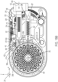
FIGS. 2 and3 provide a top and a bottom perspective view (respectively) of the external appearance of anexemplary device 100. Solely for ease of explication,FIGS. 2 to FIGS. 27A ,27B, and 27C will use the x, y, z directional system depicted byarrows 201. The symbol ⊙ shall represent an arrow coming out of the page, while the symbol ⊗ shall represent an arrow going into the page. In the specification and claims, references to the "up," "upward," "upper," or "top" direction shall mean the positive z direction; references to the "down," "downward," "lower," or "bottom" direction shall mean the negative z direction; references to the "proximal" direction shall mean the negative x direction; references to the "distal" direction shall mean the positive x direction; references to the "left" direction shall mean the positive y direction; references to the "right" direction shall mean the negative y direction; references to the "horizontal" plane shall mean the x-y plane; and references to the "vertical" plane shall mean the x-z or y-z plane, as appropriate. -
Device 100 comprises anupper housing 101 and alower housing 103 that house the internal components of the device.Loading button 102 protrudes from a distal end of the device,dosing button 104 protrudes upward fromupper housing 101, while on-body sensor button 106 (e.g., unlocking button 106) protrudes downward fromlower housing 103.Lower housing 103 also defines a needle aperture 108 (seeFIG. 3 ) through which a needle of a needle assembly may protrude when it is inserted into the patient. -
FIGS. 4 ,5 , and6 display the internal components ofdevice 100 whenupper housing 101 has been removed.FIG. 4 provides a top-down view ofdevice 100;FIG. 5 provides a perspective view ofdevice 100; andFIG. 6 provides an exploded, perspective view ofdevice 100. - In the embodiment depicted in
FIGS. 4-6 ,cartridge 300 may take the form of a round carousel having a generally planartop surface 301 and a generally planar bottom surface 303 (seeFIG. 6 ).Cartridge 300 has acentral shaft 310 extending through a central, vertical axis of the cartridge from the top surface to the bottom surface. Thecentral shaft 310 may be configured to accommodate acentral spindle 302 that extends vertically upward from the inner surface of lower housing 103 (seeFIG. 6 ). Whencentral spindle 302 is inserted throughcentral shaft 310,carousel 300 is configured to rotate aboutcentral spindle 302.Carousel 300 defines a plurality of cavities 304a, b, c, etc. (collectively or individually referred to herein as a "cavity" or "cavities" 304, as appropriate). Eachcavity 304 extends radially outward from thecentral shaft 310 towards the radial perimeter of the cartridge and includes an opening in thetop surface 301 and an opening in thebottom surface 303. - Each
cavity 304 houses aneedle assembly 306a, b, c (collectively or individually referred to herein as a "needle assembly" or "needle assemblies" 306, as appropriate). One exemplary embodiment of aneedle assembly 306 is depicted inFIGS. 22A and 22B . In this embodiment,needle assembly 306 comprises a J-shaped needle orcannula 312 having afirst leg segment 324 which is configured to penetratedrug septum 182 and draw fluid drug therefrom, as described below, and asecond leg segment 326 which is configured to be driven into a patient's body to inject the drug.Needle 312 is held within asupport hub 314 having aneedle supporting base 316. In addition to holding and supportingneedle 312,needle supporting base 316 also mounts aledge 328.Needle supporting base 316 also mounts anupstanding arm part 320 topped with atang 322. Additionaldetails regarding cartridge 300,cavities 304, and/orneedle assemblies 306 are further described inU.S. Patent No. 9,149,578, filed Nov. 17, 2011 - Returning to
FIGS. 4-6 ,cartridge 300 includes an intermittently rotating drive. For example,cartridge 300 comprises a plurality ofGeneva wheel members 308a, b, c (collectively or individually referred to herein as a "Geneva wheel member" or "Geneva wheel members" 308, as appropriate) which interact with aGeneva wheel 410 to index oradvance cartridge 300 one increment at a time, as described in further detail below. Each Geneva wheel member comprises a substantially planar member that extends radially outward in the horizontal plane fromcartridge 300. Each respective Geneva wheel member may comprise a vertical, concave, arcuate wall 309 (seeFIG. 5 ) at the furthest extent of such respective wheel member away fromcentral shaft 310. When a Geneva wheel member is aligned withGeneva wheel 410, this vertical,concave wall 309 fits againstinner hub 411 of Geneva wheel 410 (seeFIG. 5 ).Geneva wheel 410 further comprises aGeneva pin 412 that extends vertically upward from a horizontal plane ofGeneva wheel 410. Every pair of adjacent Geneva wheel members (e.g., 308a and 308b) define a gap in-between said wheel members into whichGeneva pin 412 may fit. - Reservoir 150 (best seen in
FIG. 6 ), which in this embodiment takes the form of an elastomeric container, is configured to contain a drug.Reservoir 150 may be provided to users pre-filled with drug or may be configured to be filled by users. Pump 180 (also best seen inFIG. 6 ) in this embodiment takes the form of a rotary plunger pump. Examples of suitable rotary plunger pumps are disclosed inU.S. Prov. App. No. 62/891,600, entitled "ROTARY PLUNGER PUMP SUBSYSTEMS" and filed on August 26, 2019 reservoir 150 towardsdrug septum 182, where it can be pushed into an individual needle and from there into a patient. - Energy transfer, storage, and
release mechanism 200, shown inFIGS. 5-6 , includes asecondary slide 202, aprimary slide 210, alatch 216, adosing button lock 224, ablocker 226, aface gear 230, a geartrain comprising gears latch assembly 250. Each of these components shall now be discussed in turn. -
Secondary slide 202 is attached or mechanically joined via one or more intermediate mechanical components (e.g., gears, rods, wires, or the like) toloading button 102.Slide 202 is configured to slidably move parallel to the x-axis ofdevice 100 between a secondary slide distal position and a secondary slide proximal position, as described in further detail below.FIG. 11 provides a more detailed view of one embodiment ofsecondary slide 202. In this embodiment,secondary slide 202 takes the form of a hollow and substantially rectangular-shaped member having its long axis aligned with the x-axis ofdevice 100.Slide 202 comprises a firstleft wall 201, a secondright wall 203, abottom wall 205, adistal wall 207, an opentop channel 209 defined between body portions of the left andright walls proximal channel 211 defined at the proximal end of the slide between ends of the left andright walls Slide 202 also comprises aloading button support 213 extending fromdistal wall 207, which is configured to be attached or mechanically joined via one or more intermediate components toloading button 102.Secondary slide 202 also comprises alocking tab 206 extending horizontally outward from theleft wall 201 ofslide 202 and acompression tab 208 extending horizontally outward from theright wall 203 ofslide 202.Secondary slide 202 houses a spring 204 (seeFIGS 4-6 ) within thechannel 209. A distal end ofspring 204 abuts an interior surface ofdistal wall 207, and a proximal end ofspring 204 abuts a tab (not shown) extending downwards from an interior surface ofupper housing 101. -
FIG. 8 depicts a perspective view ofdevice 100 from a different angle. For simplicity and clarity, certain components have been removed from the view ofdevice 100 inFIG. 8 . As depicted inFIG. 8 ,secondary slide 202 also includes one or more slide racks (two shown): a downward-facingslide rack 241 and a side-facingslide rack 243. Downward-facingslide rack 241 projects horizontally outward from theleft wall 201 of secondary slide 202 (i.e., on the +y side of slide 202) and has teeth that face downwards (i.e., in the -z direction) which interact with gear 232 (described in more detail below). Side-facingslide rack 243 projects proximally from the proximal end of secondary slide 202 (shown coupled to the proximal end portion of the left wall 201) and has teeth that face in the +y direction. The teeth from the side-facing slide rack interact withteeth 408 ofpinion coupler 406, as described in more detail below. - Returning to
FIGS. 4-6 ,primary slide 210 is configured to slidably move parallel to the x-axis ofdevice 100 between a primary slide distal position and a primary slide proximal position, as described in further detail below.FIG. 12 provides a more detailed view of one embodiment ofprimary slide 210. In this embodiment,primary slide 210 takes the form of a hollow and substantially rectangular-shaped member that also has its long axis aligned with the x-axis ofdevice 100.Primary slide 210 comprises a firstleft wall 215, a secondright wall 217, abottom wall 219, adistal wall 221, aproximal wall 225, and an opentop channel 223 defined between the body portions of the left andrights walls Primary slide 210 also comprises alocking tab 214 extending horizontally outward from theright wall 217 of slide 210 (i.e., the -y side), and a pair offins 227 that extend proximally fromproximal wall 225.Left wall 215 andright wall 217 defineslots 211 extending laterally (y-direction) therethrough, andfins 227 definechannels 220 extending laterally (y-direction) therethrough. Whendevice 100 is fully assembled (seeFIGS. 4-6 ),compression tab 208 ofsecondary slide 202 is configured to extend throughslots 211 and through the interior volume ofprimary slide 210.Primary slide 210 also houses aspring 212 within itschannel 223. A distal end ofspring 212 abuts a proximal surface ofcompression tab 208 ofsecondary slide 202, and a proximal end ofspring 212 abuts an interior surface ofproximal wall 225 ofprimary slide 210. -
Latch 216 is configured to rotate in the horizontal plane aroundaxis 229 and comprises alatch tab 218. Whenlatch 216 is rotated in a counter-clockwise direction (when viewed from the top down), an anti-over-rotation mechanism (shown as a spring 222) preventslatch 216 from over-rotating and also biases latch 216 in a clockwise direction back to its neutral position (i.e., as shown inFIGS. 4-5 ), where a long axis oflatch 216 is parallel to the x-axis ofdevice 100. The anti-over-rotation mechanism may also include a pin or plate with a spring configured to function as described above. -
Dosing button lock 224 interacts with other components to prevent the depressing ofdosing button 104 by the user until the on-body sensing button 106 is depressed.Dosing button lock 224 is depicted in greater detail inFIGS. 13A and 13B . In this embodiment,lock 224 comprises avertical panel 232 that defines apin slot 244.Slot 244 may extend diagonally in a +x/+z direction.Lock 224 also comprises ahorizontal panel 237 extending from thevertical panel 232, such as, for example, in an orthogonal manner.Horizontal panel 237 defines anotherpin slot 247, which extends in a +x direction.Horizontal panel 237 also comprises ablocker member 236, which takes the form of a substantially flat tab aligned with the horizontal plane, extending from a distal end ofhorizontal panel 237 beyond thevertical panel 232.Member 236 is also shown extending laterally beyond thevertical panel 232 in the -y direction. -
FIG. 7A provides a cross-sectional, perspective view ofdevice 100 when cut along plane 1-1 (seeFIGS. 4-5 ), and best depicts howdosing button lock 224 interacts with on-body sensing button 106 whendevice 100 is fully assembled. For clarity,lower housing 103 has been rendered transparent. On-body sensing button 106 can translate up and down into or out of asensing button cavity 120, which is defined withinlower housing 103.Button 106 also comprises a verticalsensing button shaft 116 and around which is coaxially surrounded by asensing button spring 114. A top end ofspring 114 abuts an interior surface ofcavity 120, while a bottom end ofspring 114 abuts an interior, top surface ofbutton 106.Spring 114biases button 106 downward out ofcavity 120. When the user presses the bottom side ofdevice 100 against his/her body, the user's pressing force overcomes the biasing force ofspring 114 and causesbutton 106 to translate upward intocavity 120. When the pressing force is removed, the spring force allows thebutton 106 to return to its biased-out position. Apin 118 is configured to extend in a horizontal direction from the left side ofshaft 116. Whendevice 100 is assembled,pin 118 is configured to ride withinpin slot 244 ofdosing button lock 224. As discussed in further detail below, the interaction ofpin 118 withpin slot 244 ofdosing button lock 224 causesdosing button lock 224 to translate proximally (i.e., in the -x direction) whenbutton 106 is pushed upward intocavity 120. - Returning to
FIGS. 4-6 ,blocker 226 interacts withdosing button lock 224 to prevent the user fromdepressing dosing button 104 until it has been unlocked, i.e., until the on-body sensing button 106 is depressed. When thedosing button 104 is unlocked and depressed,blocker 226 also interacts with latch assembly 250 (described in further detail below) to release energy stored bymechanism 200.Blocker 226 is depicted in greater detail inFIGS. 14A and 14B . In this embodiment,blocker 226 comprises three parts: a blockingtab 242, abutton seat 239, and anarm 275.Button seat 239 takes the form of a substantially planar surface or member (in this embodiment, having the shape of a circle, but other shapes are also possible) oriented parallel to the horizontal plane ofdevice 100. Blockingtab 242 is attached to the left side (i.e., the +y side) ofbutton seat 239 and takes the form of a substantially planar surface or member oriented parallel to the vertical plane ofdevice 100 that extends in both of the +y/+z directions away from theseat 239.Arm 275 is also attached tobutton seat 239, circumferentially spaced away from thetab 242, extending approximately in the +x direction.Arm 275 comprises afin 232 disposed on a distal end thereof, extending in the +y direction.Fin 232 comprises atop surface 260, abottom surface 262, aproximal surface 266, and adistal surface 268. As best seen inFIG. 14B ,top surface 260 andbottom surface 262 are angled diagonally; that is, they are parallel to a plane oriented in a -x/+z direction. -
FIG. 7B provides a perspective, cross-sectional view ofdevice 100 when cut along plane 2-2 (seeFIGS. 4-5 ). BothFIG. 7B andFIG. 6 best depict howblocker 226 interacts withdosing button 104 and withdosing button lock 224 whendevice 100 is fully assembled. As depicted inFIG. 6 , when the user has not yet depressed the on-body sensing button 106,blocker member 236 ofdosing button lock 224 is disposed beneathbutton seat 239 ofblocker 226. The position ofblocker member 236 beneathbutton seat 239 ofblocker 226 preventsblocker 226 from translating downwards. As discussed in further detail below, when the user presses the on-body sensing button 106 upwards, the interaction betweenpin 118 andpin slot 244 ofdosing button lock 224 causesdosing button lock 224 to translate in a proximal direction (i.e., in the -x direction) such thatblocker member 236 clearsbutton seat 239, thus unlockingblocker 226 and allowingblocker 226 to translate downwards. -
Dosing button 104 can translate up and down into or out of adosing button cavity 121, which is defined within upper housing 101 (seeFIG. 7B ).Dosing button 104 comprises a verticaldosing button shaft 112 which is coupled withblocker 226 such thatbutton 104 andblocker 226 translate up and down together. In the embodiment depicted inFIG. 7B ,dosing button shaft 112 is coupled withblocker 226 using a screw, though any suitable method of fixed attachment may be used (e.g., heat staking, one-way snaps, etc.). Adosing button spring 110 coaxially surroundsdosing button shaft 112. A top end ofspring 110 abuts a bottom surface ofbutton 104, while a bottom end ofspring 110 abuts an interior, upward-facing surface ofdosing button cavity 121.Spring 110 biases button 104 (andblocker 226, which is attached to button 104) upwards. When a user presses down onbutton 104,shaft 112 transmits the user's downward pressing force ofbutton 104 tobutton seat 239 ofblocker 226. Whenblocker 226 is unlocked as described previously, the user's downward pressing force causesbutton 104 and blocker 226 (including button seat 239) to translate downward. -
Mechanism 200 also comprisesface gear 230 and a geartrain comprising gears FIG. 6 .Face gear 230 takes the form of a circular-shaped gear that includes a plurality of upward-facingteeth 231.Face gear 230 is coupled to aclock spring 228. Bothface gear 230 andclock spring 228 are disposed parallel to the horizontal plane and are configured to rotate about acentral axis 233.Clock spring 228 resists rotational movement offace gear 230 aroundcentral axis 233. Put another way, rotatingface gear 230 aroundcentral axis 233 in a first rotational direction adds tension toclock spring 228, thus storing potential energy withinclock spring 228.Face gear 230 interacts with and drives gear 240, which in turn interacts with and drives gear 232.Gear 232 also interacts and drivessmall gear 234 which is rotationally coupled withgear 235 such that gears 234 and 235 rotate together.Gear 235 in turn interacts withgear 238, which provides rotational torque to pump 180. The number of gears, relative sizes of gears and teeth, and configuration may be selected to provide the rotational speed and torque needed to drive the pump. -
FIGS. 9 and10 provide additional, more detailed views offace gear 230 andclock spring 228, and how they interact withlatch 216.FIG. 9 provides a top perspective view in which certain components (e.g., slides 202, 210,blocker 226,dosing button lock 224, and latch assembly 250) have been removed to exposeface gear 230 andclock spring 228, andFIG. 10 provides a bottom perspective view in whichbottom housing 103 has been rendered transparent to better view the underside offace gear 230. As can be seen inFIG. 9 , the top surface offace gear 230 defines a plurality ofnotches 270a, b, c, d, e (collectively or individually referred to herein as "notch" or "notches" 270, as appropriate). While the embodiment offace gear 230 depicted inFIG. 9 defines five notches (notch 270c is obscured beneathgear 240 inFIG. 9 ), other embodiments are also possible in which facegear 230 defines fewer or more notches. Notches are shown spaced radially from one another and may be spaced equi-radially. Each notch is shaped to accommodate apawl 256, as described in further detail below in reference toFIG. 23A . As best seen inFIG. 10 ,face gear 230 also comprises a plurality offins 272a, b, c, d, e (collectively or individually referred to herein as "fins" or "fin" 272, as appropriate). Once again, while the embodiment offace gear 230 depicted inFIGS. 9 and10 comprises five fins, other embodiments are also possible in which facegear 230 comprises fewer or more fins. Fins are shown spaced radially from one another and may be spaced equi-radially. Each fin extends radially outward in the horizontal plane from the outer circumference offace gear 230 and comprises a sloped leading edge and a trailing straight edge. As shown, the fins may be radially offset from the notches. Also as best seen inFIG. 10 ,latch 216 further comprises a downward-extendingarm 274 that extends down from the horizontal plane oflatch tab 218 to the horizontal plane offace gear 230. Each fin 272 is sized and placed such that they will push against and displacearm 274 radially outward whenface gear 230 rotates to a position in which such fin 272 is aligned witharm 274, as discussed in further detail below. -
Latch assembly 250 is visible in the distal-right corner ofdevice 100 inFIGS. 4-5 and depicted in greater detail inFIGS. 23A-C . Latch assembly comprises alatch support 254 that secureslatch assembly 250 tobottom housing 103.Latch support 254 has a first end 255 and asecond end 257. First end 255 ofsupport 254 is attached to an interior surface ofbottom housing 103, whilesecond end 257 ofsupport 254 supports alatch pin 252 and apawl 256. Bothlatch pin 252 andpawl 256 may rotate in the horizontal plane aboutaxis 264. A torsion v-spring 258 is disposed betweenlatch pin 252 andpawl 256 and coupled to both components such that rotation oflatch pin 252 aroundaxis 264 also imparts rotational forces onpawl 256, and vice versa. Whendevice 100 is fully assembled,latch pin 252 is configured to interact withfin 232 ofblocker 226 andpawl 256 is configured to interact withface gear 230, as described in further detail below. -
Cartridge indexing mechanism 400 is depicted inFIGS. 4-5 .Mechanism 400 includes apinion coupler 406 havingteeth 408 that interact and are driven to rotate with teeth of side-facingslide rack 243 whenrack 243 is linearly translated.Pinion coupler 406 is rotationally coupled withGeneva wheel 410 such that rotation ofpinion coupler 406 drives rotation ofGeneva wheel 410.Geneva wheel 410 may be shaped as a substantially planar disc having a first circumference, and aninner hub 411 having a second circumference smaller than the first circumference stacked on top of said planar disc. AGeneva pin 412 extends vertically upwards from a top surface of the planar disc.Geneva pin 412 interacts with Geneva wheel members 308 ofcartridge 300 by fitting in the gaps between adjacent wheel members, as best seen inFIG. 4 . - Needle insertion /
retraction mechanism 500 is depicted inFIGS. 4-6 and inFIGS. 22A and 22B .Mechanism 500 comprises a drive member orhammer 502. A proximal end ofhammer 502 includes ahead 503 which interacts withneedle assemblies 306 withincartridge 300 that are operationally aligned to engage withhammer 502, as discussed in further detail below. A distal end ofhammer 502 includespins 504 and 506 (seeFIGS. 22A and 22B ). Whendevice 100 is fully assembled,hammer 502 is configured to rotate aboutpin 506, which is secured to eitherupper housing 101 or lower housing 103 (not shown inFIGS. 22A and 22B ). Whendevice 100 is assembled, pin 504 ofhammer 502 is also configured to slot intochannel 220 defined withinfins 227 of primary slide 210 (seeFIG. 5 ). Proximal or distal translation ofprimary slide 210 therefore exerts a force onpin 504 ofhammer 502, thus causinghammer 502 to rotate aboutpin 506. - The operation of
device 100 will now be described.FIGS. 15A-D depict a series of states ofdevice 100 in operation, according to some embodiments.FIG. 15A depictsdevice 100 in an initial neutral state, before the user beginsdepressing loading button 102. While in this neutral state,spring 204 ofsecondary slide 202 biases slide 202 in the distal direction to hit a stop (e.g., a surface ofsecondary slide 202 hits a stop in theupper housing 101 orlower housing 103, or when a distal surface ofcompression tab 208 hitsdistal wall 221 of primary slide 210). The position ofsecondary slide 202 in this initial neutral state ofdevice 100 is referred to herein as the secondary slide distal position. Similarly, while in this neutral state,spring 212 ofprimary slide 210 biases slide 210 in the distal direction until it hits a stop in theupper housing 101 or lower housing 103 (not shown). The position ofprimary slide 210 in this initial neutral state ofdevice 100 is referred to herein as the primary slide distal position.Geneva pin 412 is initially engaged between two Geneva wheel members 308 ofcartridge 300, labeled 308a and 308b inFIG. 15A . -
FIG. 15B depicts what happens when a user begins to apply a force in the proximal direction onloading button 102, as depicted byarrow 606. Movement ofloading button 102 in the proximal direction causessecondary slide 202 to translate in the proximal direction parallel to the x-axis ofdevice 100, thus compressingspring 204 against the tab (not shown) extending downwards from the interior surface ofupper housing 101.Compression tab 208 ofsecondary slide 202 also translates in the proximal direction withinprimary slide 210, thus compressingspring 212 against the interior surface ofproximal wall 225 ofprimary slide 210. In this way, movement ofsecondary slide 202 in the proximal direction compresses bothspring 204 andspring 212. Assecondary slide 202 translates in the proximal direction, lockingtab 206 eventually pushes againstlatch tab 218 oflatch 216. Both lockingtab 206 andlatch tab 218 comprise sloped surfaces that, when pushed together, causes latch 216 to rotate counter-clockwise (when viewed from the top down) aboutaxis 229, as shown byarrow 608 inFIG. 15C . Eventually, assecondary slide 202 continues to translate proximally, lockingtab 206 clearslatch tab 218, at whichpoint latch 216 rotates clockwise (when viewed from the top down) aboutaxis 229, as shown byarrow 610 inFIG. 15D , due to the biasing pressure ofspring 222. As depicted inFIG. 15D ,latch tab 218 slides into place behind (i.e., distal to)locking tab 206, thus preventingsecondary slide 202 from translating distally. The position ofsecondary slide 202 depicted inFIG. 15D is referred to herein as the secondary slide proximal position. - Proximal movement of
secondary slide 202 also causes side-facingslide rack 243 to translate in the proximal direction, as shown byarrow 604 inFIGS. 15B-D . Due to the engagement between the teeth of side-facingslide rack 243 andteeth 408 ofpinion coupler 406, proximal movement of side-facingslide rack 243 causespinion coupler 406 to rotate in the clockwise direction (when viewed from the top down), as shown byarrow 602. Due to the rotational coupling betweenpinion coupler 406 andGeneva wheel 410,Geneva wheel 410 also rotates in the direction ofarrow 602. Rotation ofGeneva wheel 410 causesGeneva pin 412 to disengage from the gap between the twoGeneva wheel members pin 412 was initially engaged, as shown inFIG. 15B . AsGeneva wheel 410 continues to rotate, pin 412 re-engages with the next gap defined between two Geneva wheel members (308b, 308c) oncartridge 300 in the clockwise direction, as shown inFIG. 15D . This disengagement and re-engagement ofpin 412 within the next gap between Geneva wheel members allowscartridge 300 to advance or index one increment in the counter-clockwise direction (when viewed from the top down), as depicted byarrow 612. When thepin 412 is in re-engagement, thepin 412 maintain its position so that the cartridge does not rotate, and theGeneva wheel 410 is inhibited from further rotation as there is disengagement of side-facingrack 243 fromteeth 408, which is depicted inFIG. 18C . - By the end of the sequence of states depicted by
FIGS. 15A-D , work done by the user in pressingloading button 102 has been converted into potential energy stored in thecompressed springs latch tab 218, which preventssecondary slide 202 from translating distally and releasing the springs. This potential energy is also prevented from being released byblocker 226, which preventsprimary slide 210 from translating proximally (as described below). The work done by the user has also been used to index or advance thecartridge 300 by one increment, thus moving one spent or used needle assembly out of operational alignment with drive member orhammer 502, and placing a new, unused needle assembly into operational alignment withhammer 502. -
FIGS. 16A and 16B show the proximal movement ofsecondary slide 202 caused by depression ofloading button 102 from the +y side ofdevice 100.FIG. 16A shows the state ofdevice 100 in its neutral state, beforeloading button 102 is pressed.FIG. 16B depicts the proximal movement ofbutton 102 as the user depresses it, as shown byarrow 606. Proximal movement ofbutton 102 causessecondary slide 202 to translate proximally, which in turn causes downward-facingslide rack 241 to also translate proximally (sinceslide rack 241 is mounted to secondary slide 202). Due to the engagement between the downward-facing teeth of downward-facingslide rack 241 andgear 232, proximal movement of downward-facingslide rack 241 causes gear 232 to rotate in the direction indicated byarrow 614. -
FIGS. 17A and 17B show the results ofrotating gear 232 in the direction ofarrow 614. For clarity, certain components (e.g.,primary slide 210 and drug reservoir 150) have not been depicted to better show the movement of other components. Due to the engagement betweengears gear 232 in the direction ofarrow 614 causes gear 240 to rotate in the direction ofarrow 616. Rotation ofgear 240 in the direction ofarrow 616 in turn drives facegear 230 to rotate in the direction ofarrow 618. Asface gear 230 is rotated in the direction ofarrow 618, tension is added toclock spring 228. As previously discussed,face gear 230 defines a plurality ofnotches 270 on the top surface thereof. Asface gear 230 rotates in the direction ofarrow 618, one of thesenotches 270 eventually aligns withpawl 256 oflatch assembly 250. When this alignment occurs,pawl 256 slides intonotch 270 under the biasing pressure of torsion v-spring 258, thus preventingface gear 230 from rotating counter to the direction indicated byarrow 618. - By the end of the sequence of states depicted by
FIGS. 16A-B andFIGS. 17A-B , the work done by the user in pressingloading button 102 has also been converted into potential energy stored in the rotational tension ofclock spring 228. This potential energy is prevented from being released bypawl 256, which interacts with one of thenotches 270 offace gear 230 to preventface gear 230 andclock spring 228 from unwinding. - After
cartridge 300 has been advanced one increment (as described above inFIGS. 15A-D ) and afterface gear 230 has been rotated and locked (as described above inFIGS. 16A-B and17A-B ), side-facingslide rack 243 may be disengaged fromteeth 408 ofpinion coupler 406, and downward-facingslide rack 241 may be disengaged fromgear 232. Disengagement of side-facingrack 243 fromteeth 408 is depicted inFIGS. 18A-C , which depict a top-down view ofdevice 100. For clarity,secondary slide 202 has been rendered transparent using dashed lines in order to reveal the components underneath it. As apparent from this view, both side-facingslide rack 243 and downward-facingslide rack 241 are mounted to a commonslide rack platform 249.Slide rack platform 249 is a substantially planar structure that lies in the horizontal plane ofdevice 100 and is in turn mounted belowsecondary slide 202.Platform 249 defines twoslide rack slots underside pins bottom wall 205 ofsecondary slide 202 fit into theslide rack slots -
FIG. 18A depicts an initial, neutral state ofdevice 100 in whichsecondary slide 202 is positioned at its furthest distal extent (i.e., in the secondary slide distal position such as inFIG. 15A ). InFIG. 18B ,secondary slide 202 translates proximally in the direction ofarrow 604 in response to the user depressingloading button 102, as previously described. Assecondary slide 202 translates proximally,underside pins slide rack slots platform 249, downward-facingslide rack 241, and side-facingslide rack 243 to also translate proximally. Whensecondary slide 202 completes its proximal translation,platform 249 may continue to slide in the proximal direction such that underside pins 274a, 274b now engage the distal edges ofslide rack slots FIG. 18C . Sinceslide rack slots platform 249 in the -x direction causesplatform 249 to also translate in the -y direction, as illustrated byarrow 607, radially away from thepinion coupler 406. This translation in the -y direction causes the teeth of side-facingslide rack 243 to disengage fromteeth 408 ofpinion coupler 406. -
FIGS. 19A-C depict the same sequence of states ofdevice 100 from a different angle, and best illustrates how downward-facingslide rack 241 disengages fromgear 232. Similar toFIG. 18A ,FIG. 19A depicts the initial neutral state ofdevice 100.FIG. 19B shows how the downward-facingslide rack 241 translates proximally (in the -x direction, as indicated by arrow 605) in response to the user depressingloading button 102, as previously described. Whenplatform 249 translates in the -x/-y direction, as previously described and illustrated inFIG. 18C , downward-facingslide rack 241 also translates in the -x/-y direction, as shown byarrow 609 inFIG. 19C . This causes the teeth of downward-facingslide rack 241 to disengage from the teeth ofgear 232. - After
device 100 has been loaded by pressingloading button 102 andslide racks gear 232 andpinion coupler 406, respectively,device 100 is ready to be placed onto the patient's body for an injection.FIG. 20A shows the configuration ofdevice 100 after it has been loaded, but before it has been pressed against the patient's body. In this configuration,blocker member 236 ofdosing button lock 224 is positioned underneathblocker 226, thus preventingblocker 226 from translating downwards. This prevents the user from triggeringdevice 100 prematurely.FIG. 20B depicts what happens when the user pressesdevice 100 against the patient's body.Pressing device 100 against the patient's body exerts an upward force on the on-body sensing button 106, which overcomes the downward biasing pressure ofsensing button spring 114 and causesbutton 106 to translate upwards intosensing button cavity 120 in the direction ofarrow 620. As on-body sensing button 106 translates upwards, pin 118 rides withinpin slot 244 ofdosing button lock 224, as previously described. Sincepin slot 244 invertical panel 232 extends diagonally in the +x/+z direction, the movement ofpin 118 upwards withinpin slot 244 also causesdosing button lock 224 to translate in the proximal direction (i.e., in the -x direction), as illustrated byarrow 622. Asdosing button lock 224 translates proximally,blocker member 236 clearsblocker 226, thus allowingblocker 226 to translate downwards (i.e., in the direction of arrow 624). This unlocksdosing button 104, thus readyingdevice 100 for an injection. -
FIG. 21A depicts the configuration ofdevice 100 after it has been pressed against the patient's body (thus unlocking dosing button 104), but before thedosing button 104 has been depressed. In this state, blockingtab 242 ofblocker 226 is positioned in front of lockingtab 214 ofprimary slide 210, thus preventingprimary slide 210 from translating proximally in the -x direction. As previously discussed, this position ofprimary slide 210 is referred to herein as the primary slide distal position.FIG. 21B depicts what happens when the user depressesdosing button 104. Asdosing button 104 is depressed downward in the direction ofarrow 624, the downward force provided by the user overcomes the upward biasing pressure ofdosing button spring 110 and causesbutton 104 to translate downwards. The downward force onbutton 104 is transmitted toblocker 226 viadosing button shaft 112. This causesblocker 226 to also translate downwards in the direction ofarrow 626. Asblocker 226 translates downwards, blockingtab 242 clears thelocking tab 214 ofprimary slide 210, thus allowingprimary slide 210 to translate proximally in the direction of arrow 628 (i.e., in the -x direction). Sincespring 212 has been previously compressed by proximal movement ofcompression tab 208 of secondary slide 202 (as previously described),primary slide 210 is propelled proximally by the loadedspring 212 once blockingtab 226 clears lockingtab 214. The position ofprimary slide 210 when it has translated to its maximum proximal extent is referred to herein as the primary slide proximal position. -
FIGS. 22A-B provide profile views ofdevice 100 showing how proximal movement ofprimary slide 210 drives aneedle assembly 306 withincartridge 300 from a retracted position to an injection position.FIG. 22A shows the configuration ofdevice 100 before the user pressesdosing button 104. In this state,needle assembly 306 is disposed in a retracted position withincavity 304 ofcartridge 300. Whenprimary slide 210 is propelled forward byspring 212,primary slide 210 exerts a proximal force in the direction ofarrow 630 onpin 504 ofhammer 502. This proximal force causes hammer 502 to rotate aroundpin 506 in the direction ofarrow 631. Ashammer 502 rotates in the direction ofarrow 631,hammer head 503 pushes down onledge 328 of aneedle assembly 306 withincartridge 300 that is in operational alignment withhammer 502, thus driving that needle assembly downwards in the direction ofarrow 632 to an injection position, as shown inFIG. 22B . Asneedle assembly 306 translates downwards,first leg segment 324 ofneedle 312 penetratesdrug septum 182, whilesecond leg segment 326 ofneedle 312 projects downward out ofneedle aperture 108 inlower housing 103, punctures the patient's skin and into the patient's body. In this way, whenneedle assembly 306 is in its injection position,needle 312 establishes a fluid path fromdrug septum 182 into the patient's body. When the needle assembly is disposed in the injection position, the biasing force ofspring 212 biasesprimary slide 210 in the proximal direction, thus causinghammer head 503 to maintain downward pressure onledge 328 until the needle assembly is retracted (as described below). This ensures the needle assembly maintains its proper depth within the patient's body and in thedrug septum 182. - In addition to unlocking
primary slide 210, downward translation ofblocker 226 also driveslatch assembly 250 to unlockface gear 230. The interaction betweenblocker 226 and latchassembly 250 is best depicted inFIGS. 23A-C. FIG. 23A shows the spatial position ofblocker 226 relative to latchassembly 250 before the user presses down ondosing button 104. In this initial position,fin 232 ofblocker 226 is positioned just abovelatch pin 252 oflatch assembly 250. Asblocker 226 is driven downwards when the user depressesbutton 104,bottom surface 262 offin 232 contacts latchpin 252. Sincebottom surface 262 is angled diagonally in a -x/+z direction, downward movement ofbottom surface 262 causespin 252 to rotate horizontally in the direction indicated by arrow 638 around axis 264 (seeFIGS. 23B and 23C ). Aspin 252 rotates in the direction of arrow 638, torsion v-spring 258 transmits rotational torque onpawl 256 in the direction of arrow 640 (again around axis 264). -
FIGS. 24A-C show the interaction betweenblocker 226 and latch assembly 250 from another angle.FIG. 24A shows the state ofdevice 100 after the user has loaded the device by depressingloading button 102, but before the user has depressedbutton 104. In this state, work done by the user indepressing loading button 102 is stored in the form of potential energy within coiledclock spring 228, which is coupled to facegear 230. However,face gear 230 andclock spring 228 are prevented from unwinding bypawl 256, which fits within one of thenotches 270 defined onface gear 230. As the user depressesdosing button 104,button 104 translates downward in the direction ofarrow 624. This downward force onbutton 104 causesblocker 226 to also translate downward and, as previously discussed, causeslatch pin 252 to rotate in the direction of arrow 638, andpawl 256 to rotate in the direction ofarrow 640. Rotation ofpawl 256 in the direction ofarrow 640 causes pawl 256 to disengage fromnotch 270, thus allowingface gear 230 andclock spring 228 to unwind in the direction ofarrow 642, as depicted inFIG. 24B . - Referring back to
FIG. 23C , as the user continues to push downward onloading button 104, and asblocker 226 continues to translate downward,latch pin 252 eventually leaves contact withbottom surface 262 offin 232, and instead contactsproximal surface 266 offin 232. At this point,latch pin 252 stops rotating in the direction of arrow 638. Asblocker 226 continues to translate downward,latch pin 252 clearsproximal surface 266 as theentire fin 232 slips underneathlatch pin 252. When the user stops pushing downward onbutton 104,button 104 andblocker 226 rise upward again due to the biasing pressure ofdosing button spring 110. At this point,latch pin 252 contactstop surface 260 offin 232. Sincetop surface 260 offin 232 is also angled diagonally in a -x/+z direction,top surface 260 now forceslatch pin 252 to rotate in the opposite direction aroundaxis 264, i.e., in the direction ofarrow 644. Aspin 252 rotates in the direction ofarrow 644, torsion v-spring transmits rotational torque onpawl 256 in the direction ofarrow 646. -
FIGS. 25A-C provide a view ofdevice 100 from below, in whichlower housing 103 has been rendered transparent to better show how the unwinding offace gear 230 unlatcheslatch 216.FIG. 25A depictsdevice 100 afterpawl 256 has been disengaged from one of thenotches 270 inface gear 230 andface gear 230 andclock spring 228 begin unwinding in the direction ofarrow 642. Whileface gear 230 andclock gear 228 are unwinding, the needle insertion /retraction mechanism 500 drives aneedle assembly 306 into the injection position, as previously discussed and depicted inFIGS. 22A-B . Also, whileface gear 230 unwinds, it drives rotation ofgears FIG. 6 ). Rotation ofgear 238, in turn, provides rotational input to pump 180, causingpump 180 to pump liquid drug fromreservoir 150, throughseptum 182 and the drivenneedle 312 and into the patient. -
FIGS. 28 through 35A-D depict one potential embodiment ofpump 180.Pump 180 includes mountingframe 602,rotary drive shaft 604,rotating plunger 802, pumphousing 702, and returnspring 624. A first end offrame 602 supports arotary drive shaft 604, which is in turn connected torotating plunger 802.Rotary drive shaft 604 may be connected to gear 238, which provides rotational input to pump 180 that causesrotary drive shaft 604 to rotate aboutlongitudinal axis 701 in the direction of arrow 705 (e.g., in a clockwise direction), as shown inFIG. 29 . -
FIGS. 30A-30D and31 depict therotating plunger 802 in more detail, according to some embodiments.FIGS. 30A-30D depictplunger 802 from four separate profile views, whileFIG. 31 provides a perspective view.Plunger 802 comprises a substantially cylindrical elongated body having afirst end 812 and asecond end 814 connected by curved,cylindrical side wall 820.Plunger pin 804 protrudes radially outward fromside wall 820 ofplunger 802 and may be rigidly affixed thereto. In some embodiments,pin 804 andside wall 820 may be formed of one monolithic piece; in other embodiments, pin 804 may be a separate part that is adhered, joined, inserted, or molded intoside wall 820. As depicted,pin 804 may be disposed adjacent to thefirst end 812 ofplunger 802. However, the pin may be disposed at any point along the length ofplunger 802. As best seen inFIG. 31 ,plunger 802 may include a reduced cross-sectional area portion that may be defined by acutout 810 disposed adjacent to thesecond end 814.Cutout 810 is defined by a substantially planarlongitudinal portion 816 recessed below theside wall 820 and connected to alip 818 which steps inwards from thecylindrical side wall 820 ofplunger 802.Portion 816 andlip 818 may intersect in a transverse relationship. In one embodiment,planar portion 816 ofcutout 810 faces a first radial direction, and thepin 804 extends in a second radial direction that is perpendicular to the first radial direction of the placement of the cutout. -
Plunger 802 is received withinpump housing 702. One exemplary embodiment ofhousing 702 is depicted in greater detail inFIGS. 32 and33 ;FIG. 32 provides a perspective view ofhousing 702, whileFIG. 33 provides a cross-sectional view ofhousing 202 when cut along line 3-3.Housing 702 may be constructed from any suitable and relatively rigid material, such as an olefin plastic (e.g., cyclic olefin copolymer and/or polypropylene). The interface betweenhousing 702 andplunger 802 may be lubricated with an appropriate pharmaceutical container lubricant, such as silicone oil. -
Housing 702 comprises three sections: afirst section 708, anintermediate section 710, and athird section 712, each disposed along acommon axis 701.First section 708 comprises aside wall 722 that defines anangled pin track 718.Pin track 718 is angled such that a plane defined bytrack 718 is not perpendicular tolongitudinal axis 718 but is angularly offset such that afirst end 754 oftrack 718 is further fromintermediate section 710 than the opposite,second end 750 oftrack 718.Second end 750 is connected tofirst end 754 oftrack 718 via an upwardly-slopingportion 752, and a downwardly-slopingportion 756.First section 708 also comprises twotabs support plunger 802. -
Intermediate section 710 comprises aside wall 724, and one or moreaxial ridges 714 projecting radially outward fromside wall 724. One or more of theridges 714 have a radiallyinward step 716 oriented towards thethird section 712 ofhousing 702. As best shown inFIG. 33 ,side wall 724 defines a cavity 730 internally along theaxis 701 having an openfirst end 760 and a closed second end 762.Side wall 724 also defines aninlet port 726 and anoutlet port 728, shown defined by radially extending arms. In one embodiment, theports ports transverse axis 703 that extends orthogonal to thelongitudinal axis 701.Inlet port 726 andoutlet port 728 pass throughside wall 724 and are in fluid communication with cavity 730. Ducts are shown disposed on the arms in a fluid tight seal.Inlet port 726 is fluidically connected with aninlet duct 704, whileoutlet port 728 is fluidically connected to anoutlet duct 706. During operation of the pump subsystem, fluid is sucked in throughinlet port 726 /inlet duct 704 and into the cavity 730 and expelled throughoutlet port 728 /outlet duct 706. - Returning to
FIG. 32 ,third section 712 ofhousing 702 comprises a substantially cylindrical body having a smaller cross-sectional area compared tofirst section 708 andintermediate section 710.Third section 712 may also take the form of other shapes.Return spring 724 may be wrapped aroundthird section 712 such that a first end ofspring 624 abuts theinward step 716 of one or more of theridges 714, and a second end ofspring 624 abuts and/or is received within a receptacle on mounting frame 602 (seeFIG. 28 ). Thus mounted,return spring 624 provides biasing pressure againsthousing 702. - When
plunger 802 is received withinhousing 702,plunger 802 is configured to rotate aboutlongitudinal axis 701 within cavity 730.Plunger 802 is also configured to translate longitudinally alonglongitudinal axis 701 within cavity 730. The biasing pressure ofreturn spring 624 causes thepin track 718 to abut and/or engage against the underside ofplunger pin 804 at all times whileplunger 802 rotates within cavity 730. Whenplunger 802 is received within cavity 730, the surfaces that define cutout 810 (that is, surfaces 816, 818) and the interior wall of cavity 730 (i.e., the interior surface of side wall 724) together define a working chamber 902 (seeFIGS. 34A-34D ) that is brought into repeated and sequential fluid-flow communication with no port, then the inlet port, then no port, and then the outlet port as the plunger moves within the cavity. - In operation, rotational input from
gear 238 provides a rotary force to driveshaft 604. The rotary force causesshaft 604 andplunger 802 to rotate aboutlongitudinal axis 701 in the direction of arrow 705 (seeFIG. 29 ,FIGS. 34A-34D ). Asplunger 802 rotates withincavity 802, theplunger 802 andhousing 702 successively move through the series of configurations depicted inFIGS. 34A-34D , and35A-35D . Each ofFIGS. 34A-34D show a profile, cross-sectional view ofpump subsystem 108 along line 3-3. Each ofFIGS. 35A-35D show a top-down, cross-sectional view ofpump subsystem 108 along line 4-4. For clarity, the position ofplunger pin 804 is outlined in phantom inFIGS. 35A-35D . - In
FIG. 34A andFIG. 35A ,plunger 802 is rotated such thatplunger pin 804 is pointed towards the left inFIG. 34A andFIG. 35A . Whenplunger pin 304 is pointed in this direction,spring 624 causespin 804 to engage against the lowest portion (i.e., second end 750) ofpin track 718, thus causingplunger 802 to translate longitudinally to its furthest position within cavity 730 relative tohousing 702. Whileplunger 802 is at this furthest position,distal end 814 ofplunger 802 may come into contact with the closed end 762 of cavity 730 (or be located close to the closed end 762 of cavity 730), such that workingchamber 902 has the smallest volume of any of the four configurations depicted inFIGS. 34A-34D and35A-35D . Also, whileplunger 802 is at this furthest position,cutout 810 is oriented out of the page inFIG. 34A , and downwards inFIG. 35A . As previously mentioned,cutout 810 and the interior wall of cavity 730 (i.e., the interior surface of side wall 724) define a workingchamber 902. When cutout 810 is so oriented, thecurved side wall 820 ofplunger 802 presses tightly against the interior surfaces ofside wall 724 surroundinginlet port 726 andoutlet port 728, respectively, so as to establish a fluid-tight seal that blocks both ports. As a result, workingchamber 902 is not in fluid communication with either port while in this configuration. - In
FIG. 34B andFIG. 35B ,plunger 802 is rotated such thatplunger pin 804 is pointed into the page inFIG. 34B , and upwards inFIG. 35B . Whenplunger pin 804 is pointed in this direction,spring 624 causespin 804 to engage against upwardly-slopingportion 752 ofpin track 718. This causesplunger 802 to translate longitudinally out ofhousing 702 asplunger 802 rotates, thus increasing the volume of workingchamber 902. Also, in this configuration,cutout 810 is oriented to the left inFIG. 34B andFIG. 35B , thus opening fluid communication between workingchamber 902 andinlet port 726. The opened fluid communication and the increasing volume of workingchamber 902 causes fluid to be sucked into workingchamber 902 frominlet port 726 aspin 804 rotates (or, if the fluid is stored under pressure in the drug reservoir, allows fluid to enter working chamber 902). - In
FIG. 34C andFIG. 35C ,plunger 802 is rotated such thatplunger pin 804 is pointed to the right inFIG. 34C andFIG. 35C . Whenplunger pin 804 is pointed in this direction,spring 624 causespin 804 to engage against the highest portion (i.e., first portion 754) ofpin track 718, thus allowingplunger 802 to translate longitudinally to its furthest position out of cavity 730 relative tohousing 702. When in this configuration,distal end 814 ofplunger 802 is located at its shallowest position within cavity 730 such that workingchamber 902 is at its largest volume of any of the four configurations depicted inFIGS. 34A-34D and35A-35D . Also, when in this configuration,cutout 810 is oriented into the page inFIG. 34C , or upwards inFIG. 35C . When cutout 802 is so oriented, thecurved side wall 820 ofplunger 802 again establishes a fluid-tight seal against bothinlet port 726 andoutlet port 728, which means the workingchamber 902 is not in fluid communication with either port. - In
FIG. 34D andFIG. 35D ,plunger 802 is rotated such thatplunger pin 804 is pointed out of the page inFIG. 34D , or downwards inFIG. 35D . Whenplunger pin 804 is pointed in this direction,spring 624 causespin 804 to engage against the downwardly-slopingportion 756 ofpin track 718. This causesplunger 802 to translate longitudinally intohousing 702 asplunger 802 rotates, thus decreasing the volume of workingchamber 902. Also, in this configuration, cutout 910 is oriented towards the right inFIG. 34D and35D , thus opening fluid communication between workingchamber 902 andoutlet port 728. The opened fluid communication and the decreasing volume of workingchamber 902 causes fluid to be expelled from workingchamber 902 and out throughoutlet port 728 aspin 804 rotates. In this configuration,curved side wall 820 ofplunger 802 continues to press tightly against inwardly offset segment 732, thus maintaining the fluid-tight seal that blocksinlet port 726. - A complete pump cycle comprises the four configurations described above in
FIGS. 34A-34D and35A-35D . For further details regarding the operation and/or configuration ofpump 180, or for alternative embodiments ofpump 180 that may be used, refer toU.S. Prov. App. No. 62/891,600, entitled "ROTARY PLUNGER PUMP SUBSYSTEMS" and filed on August 26, 2019 - Now that operation of
pump 180 has been described, attention is directed back toFIGS. 25A-C . After a predetermined time (during which the drug is being pumped into the patient),face gear 230 eventually rotates into a position where one of its fins 272 come into alignment witharm 274 oflatch 216. The sloped leading edge of fin 272 comes into contact witharm 274, thus pushinglatch 216 to rotate in the direction ofarrow 644, as depicted inFIG. 25B . This causeslatch 216 to unlocksecondary slide 202, as described below. Asgear 232 continues to rotate, fin 272 eventually clearsarm 274 oflatch 216, and latch 216 moves back in the direction ofarrow 646 into its neutral position under the biasing pressure ofspring 222. -
FIGS. 26A-C depict the same sequence of states ofdevice 100 asFIGS. 25A-C from above to better show how slides 202 and 210 move in response to unlocking oflatch 216.FIG. 26A depictsdevice 100 afterpawl 256 has been disengaged andface gear 230 begins unwinding, but beforelatch 216 is unlocked. In this state,latch tab 218 oflatch 216 is positioned distal to lockingtab 206 ofsecondary slide 202, thus preventingsecondary slide 202 from translating distally under the biasing pressure ofspring 204. InFIG. 26B ,latch 216 rotates in the direction ofarrow 644, thus clearinglocking tab 206. This allowssecondary slide 202 to translate distally in the direction of arrow 648 (i.e., in the +x direction) due to the biasing pressure ofcompressed spring 204. Assecondary slide 202 translates distally,compression tab 208 contactsdistal wall 221 ofprimary slide 210 and causesprimary slide 210 to also translate distally in the direction of arrow 650 (i.e., in the +x direction). Eventually,latch 216 rotates in the direction ofarrow 646 back to its neutral position (FIG. 26C ) under the biasing pressure ofspring 222. However, since lockingtab 206 is now distal to latchtab 218, rotation oflatch 216 back to its neutral position does not stopsecondary slide 202 from translating distally until it hits a stop.Secondary slide 202 eventually translates back to its secondary slide distal position, andprimary slide 210 eventually translates back to its primary slide distal position, as depicted inFIG. 26C . -
FIGS. 27A-C depict the same sequence of states ofdevice 100 asFIGS. 25A-C and26A-C from the side to better show how distal translation ofprimary slide 210 causes the needle insertion /retraction mechanism 500 to retract theneedle 312.FIG. 27A depictsdevice 100 afterpawl 256 has been disengaged andface gear 230 begins unwinding, but beforelatch 216 is unlocked. In this state,needle assembly 306 is in its injection position andhead 503 ofhammer 502 is in contact withledge 328 ofneedle assembly 306. InFIG. 27B ,primary slide 210 begins translating distally, thus causinghammer 502 to rotate aboutpin 506 in the direction ofarrow 654. This rotation ofhammer 502 causes head 503 to contact the underside oftang 322 ofneedle assembly 306 and pull the entire needle assembly upwards in the direction ofarrow 652. This upwards motion retractsneedle assembly 306 from its injection position back to its retracted position. In particular,first leg segment 324 ofneedle 312 is drawn out ofdrug septum 182 andsecond leg segment 326 is drawn out of the patient's body, thus breaking the fluid path betweendrug septum 182 and the patient's body. Asprimary slide 210 continues to translate distally and hammer 502 continues to rotate aboutpin 506 in the direction ofarrow 654,head 503 ofhammer 502 eventually disengages fromtang 322 ofneedle assembly 306, as depicted inFIG. 27C . - The terms "first", "second", "third", "primary", "secondary", and the like, whether used in the description or in the claims, are provided for distinguishing between similar elements and not necessarily for describing a sequential or chronological order. It is to be understood that the terms so used are interchangeable under appropriate circumstances (unless clearly disclosed otherwise) and that the embodiments of the disclosure described herein are capable of operation in other sequences and/or arrangements than are described or illustrated herein.
- While this invention has been described as having exemplary designs, the present invention can be further modified within the scope of this disclosure. This application is therefore intended to cover any variations, uses, or adaptations of the invention using its general principles. Further, this application is intended to cover such departures from the present disclosure as come within known or customary practice in the art to which this invention pertains.
- For example, in some embodiments, the drug-delivery device may not comprise a needle cartridge holding a plurality of needle assemblies; instead, the device may comprise only a single needle assembly. Such a device may be configured for single-use only, rather than for multiple uses. This single needle assembly may be configured to be inserted and/or retracted using the insertion / retraction mechanisms discussed above.
- In at least some of the above-described embodiments, one or more springs in the drug-delivery device are loaded when the user actuates a loading button. When the user then actuates a dosing button, the one or more loaded springs are released to (i) operate a drive member to drive a needle assembly in operational alignment with the drive member from a retracted position to an injection position, (ii) drive a pump to pump drug fluid from a drug reservoir through the driven needle assembly, and (iii) retract the driven needle assembly from the injection position back to the retracted position. In other embodiments however, releasing the one or more loaded springs need not drive all of functions (i) through (iii) listed above. For example, in some embodiments, releasing the one or more loaded springs (upon actuation of the dosing button) may drive only function (i) but not functions (ii) and (iii). In other embodiments, releasing the one or more loaded springs upon actuation of the dosing button may drive only functions (i) and (ii) but not (iii). In yet other embodiments, releasing the one or more loaded springs upon actuation of the dosing button may drive functions (ii) and (iii), but not function (i). In general, embodiments in which releasing the one or more springs (upon actuation of the dosing button) accomplishes any one or more of functions (i) through (iii) listed above are also within the scope of this disclosure.
- Furthermore, in at least some of the above-described embodiments, the needle cartridge is indexed when the user actuates the loading button, and not when the one or more loaded springs are released when the user actuates the dosing button. In other embodiments, however, the needle cartridge may be indexed when the one or more loaded springs are released when the user actuates the dosing button.
- The 68 claims of the parent application are reproduced immediately below as clauses. These clauses define preferred embodiments. The applicant reserves the right to pursue protection for the combinations of features set out in these clauses, and/or for any other subject-matter contained in the parent application as filed, either in the present divisional application or in a further application divided from the present divisional application.
- 1. A drug-delivery device, comprising:
- a housing;
- a drug reservoir within the housing configured to contain a drug fluid;
- a drive member;
- a needle assembly disposed in a retracted position within the housing;
- a pump in fluid communication with the drug reservoir;
- one or more springs;
- a loading button coupled to the housing configured to be manually actuated to load the one or more springs using work done through actuation of the loading button; and
- a dosing button coupled to the housing configured to be manually actuated after actuation of the loading button to release the one or more loaded springs to:
- operate the drive member to drive the needle assembly from the retracted position to an injection position,
- drive the pump to pump the drug fluid from the drug reservoir through the driven needle assembly, and
- retract the driven needle assembly from the injection position to the retracted position.
- 2. The device of
clause 1, further comprising the drug fluid contained within the drug reservoir. - 3. The device of any of clauses 1-2, wherein the needle assembly includes a first needle assembly of a plurality of needle assemblies, and the plurality of needle assemblies is disposed in a needle cartridge within the housing.
- 4. The device of
clause 3, wherein actuation of the loading button advances the needle cartridge so that a second needle assembly of the plurality of needle assemblies is moved out of operational alignment with the drive member and the first needle assembly is moved into operational alignment with the drive member. - 5. The device of any of clauses 1-4, further comprising an unlocking button configured to prevent actuation of the dosing button until the unlocking button is moved to an unlocked configuration.
- 6. The device of any of clauses 1-5, wherein:
- the one or more springs comprise one or more linear springs movable between an axially expanded configuration and an axially compressed configuration;
- actuation of the loading button loads the one or more linear springs by moving the one or more linear springs to the axially compressed configuration; and
- actuation of the dosing button after actuation of the loading button releases the one or more linear springs by moving the one or more linear springs to the axially expanded configuration to operate the drive member.
- 7. The device of any of clauses 1-6, wherein:
- the one or more springs comprise one or more clock springs movable between an unwound configuration and a wound configuration;
- actuation of the loading button loads the one or more clock springs by moving the one or more clock springs to the wound configuration using work done through actuation of the loading button, and
- actuation of the dosing button after actuation of the loading button releases the one or more clock springs by moving the one or more clock springs to the unwound configuration to drive the pump.
- 8. The device of any of clauses 1-7, wherein:
- the one or more springs comprise a first linear spring and a second linear spring, each movable between an axially expanded configuration and an axially compressed configuration;
- the device further comprises a primary slide and a secondary slide, wherein:
- the primary slide is configured to slidably move parallel to a linear axis of the device between a first primary slide position and a second primary slide position,
- the secondary slide is configured to slidably move parallel to the linear axis between a first secondary slide position and a second secondary slide position,
- the primary slide is coupled to the first linear spring, and
- the secondary slide is coupled to both of the first linear spring and the second linear spring;
- the device further comprises a blocker that, until released, is configured to prevent the primary slide from moving from the first primary slide position to the second primary slide position;
- actuation of the loading button moves the secondary slide from the first secondary slide position to the second secondary slide position to move both of the first linear spring and the second linear spring to the axially compressed configuration; and
- actuation of the dosing button after actuation of the loading button releases the blocker to allow the first linear spring to move to the axially expanded configuration, wherein movement of the first linear spring to the axially expanded configuration moves the primary slide from the first primary slide position to the second primary slide position, and wherein movement of the primary slide to the second primary slide position operates the drive member.
- 9. The device of clause 8,
- further comprising a latch that, until released, is configured to prevent the secondary slide from moving from the second secondary slide position to the first secondary slide position after actuation of the loading button;
- wherein the latch is configured to be released a predetermined time after the blocker is released to allow the second linear spring to move to the axially expanded configuration, wherein movement of the second linear spring to the axially expanded configuration moves the secondary slide from the second secondary slide position to the first secondary slide position.
- 10. The device of clause 9, wherein the primary slide and the secondary slide are coupled such that movement of the secondary slide from the second secondary slide position to the first secondary slide position causes the primary slide to move from the second primary slide position to the first primary slide position, wherein movement of the primary slide to the first primary slide position retracts the driven needle assembly from the injection position to the retracted position.
- 11. The device of any of clauses 9-10, wherein the device is a re-usable device that, when the primary slide returns to the first primary slide position and the secondary slide returns to the first secondary slide position, is configured to allow a second actuation of the loading button, and then a second actuation of the dosing button after the second actuation of the loading button, to deliver a second dose of the drug fluid.
- 12. The device of any of clauses 9-11,
- further comprising a clock spring rotatable between an unwound configuration and a wound configuration, a face gear rotationally locked with the clock spring, and a pawl configured to engage with the face gear,
- wherein actuation of the loading button loads the clock spring by rotating the face gear in a first rotational direction, wherein rotation of the face gear in the first rotational direction rotates the clock spring to the wound configuration;
- wherein the pawl is configured to engage with the face gear after rotation of the clock spring to the wound configuration to prevent rotation of the face gear in a second rotational direction opposite the first rotational direction, and to prevent rotation of the clock spring to the unwound configuration;
- wherein actuation of the dosing button after actuation of the loading button dis-engages the pawl from the face gear to allow the face gear to rotate in the second rotational direction, wherein rotation of the face gear in the second rotational direction rotates the clock spring to the unwound configuration; and
- wherein rotation of the face gear in the second rotational direction by a predetermined rotational angle releases the latch to allow the second linear spring to move to the axially expanded configuration, wherein movement of the second linear spring to the axially expanded configuration moves the secondary slide from the second secondary slide position to the first secondary slide position.
- 13. The device of any of clauses 1-12, wherein the pump is a rotary plunger pump.
- 14. The device of any of clauses 1-13, wherein the device is configured to use only energy released from the one or more loaded springs to operate the drive member, to drive the pump, and to retract the driven needle assembly.
- 15. A method for operating a drug-delivery device comprising:
- actuating a loading button of the device to load one or more springs of the device using work done through actuation of the loading button;
- actuating a dosing button of the device after actuating the loading button to release the one or more loaded springs, wherein releasing the one or more loaded springs:
- operates a drive member of the device to drive a needle assembly within the device from a retracted position to an injection position,
- drives a pump of the device to pump drug fluid from a drug reservoir through the driven needle assembly, and
- retracts the driven needle assembly from the injection position to the retracted position.
- 16. The method of clause 15, wherein the drug reservoir is disposed within the device and contains a drug fluid.
- 17. The method of any of clauses 15-16, wherein the needle assembly is a first needle assembly of a plurality of needle assemblies, and the plurality of needle assemblies is disposed in a needle cartridge.
- 18. The method of clause 17, further comprising advancing the needle cartridge in response to actuation by the user of the loading button so that a second needle assembly of the plurality of needle assemblies is moved out of operational alignment with the drive member and the first needle assembly is moved into operational alignment with the drive member.
- 19. The method of any of clauses 15-18, further comprising actuating an unlocking button of the device to unlock the dosing button for actuation.
- 20. The method of any of clauses 15-19, wherein only energy released from the one or more loaded springs is used to operate the drive member, drive the pump, and retract the driven needle assembly.
- 21. A needle-insertion mechanism for a drug-delivery device, the mechanism comprising:
- a drive member;
- a needle assembly disposed in a retracted position within a housing of the drug-delivery device;
- a primary linear spring;
- a secondary linear spring;
- a primary slide configured to slidably move parallel to a linear axis of the device between a first primary slide position and a second primary slide position, wherein the primary slide is coupled to the first linear spring;
- a secondary slide configured to slidably move parallel to the linear axis of the device between a first secondary slide position and a second secondary slide position, wherein the secondary slide is coupled to the first linear spring and the second linear spring;
- a blocker that, until released, is configured to prevent the primary slide from moving from the first primary slide position to the second primary slide position;
- a loading button configured to be manually actuated to move the secondary slide from the first secondary slide position to the second secondary slide position using work done through actuation of the loading button to compress both the first linear spring and the second linear spring; and
- a dosing button configured to be manually actuated after actuation of the loading button to release the blocker to allow the primary slide to move from the first primary slide position to the second primary slide position under biasing pressure from the compressed first linear spring, wherein movement of the primary slide to the second primary slide position operates the drive member to drive the needle assembly from the retracted position to an injection position.
- 22. The mechanism of clause 21, wherein:
- the mechanism further comprises a latch that, until released, is configured to prevent the secondary slide from moving from the second secondary slide position to the first secondary slide position after actuation of the loading button; and
- the mechanism is configured to release the latch a predetermined time after the release of the blocker to allow the secondary slide to move from the second secondary slide position to the first secondary slide position under biasing pressure from the compressed second linear spring.
- 23. The mechanism of clause 22, wherein the primary slide and the secondary slide are coupled such that movement of the secondary slide from the second secondary slide position to the first secondary slide position causes the primary slide to move from the second primary slide position to the first primary slide position, wherein movement of the primary slide to the first primary slide position retracts the driven needle assembly from the injection position to the retracted position.
- 24. The mechanism of any of clauses 22-23, wherein:
- the device further comprises a clock spring rotatable between an unwound configuration and a wound configuration, a face gear rotationally locked with the clock spring, and a pawl configured to engage with the face gear;
- actuation of the loading button loads the clock spring by rotating the face gear in a first rotational direction, wherein rotation of the face gear in the first rotational direction rotates the clock spring to the wound configuration;
- the pawl is configured to engage with the face gear after rotation of the clock spring to the wound configuration to prevent rotation of the face gear in a second rotational direction opposite the first rotational direction, and to prevent rotation of the clock spring to the unwound configuration;
- actuation of the dosing button after actuation of the loading button dis-engages the pawl from the face gear to allow the face gear to rotate in the second rotational direction, wherein rotation of the face gear in the second rotational direction rotates the clock spring to the unwound configuration; and
- rotation of the face gear in the second rotational direction by a predetermined rotational angle, releases the latch to allow the secondary slide to move from the second secondary slide position to the first secondary slide position under biasing pressure from the compressed second linear spring.
- 25. A method for operating a needle-insertion mechanism for a drug-delivery device, the needle-insertion mechanism comprising a primary slide coupled to a first linear spring, a secondary slide coupled to the first linear spring and a second linear spring, and a blocker that, until released, is configured to prevent the primary slide from moving from a first primary slide position to a second primary slide position, the method comprising:
- actuating a loading button of the device to move the secondary slide from a first secondary slide position to a second secondary slide position, wherein the movement of the secondary slide axially compresses both the first linear spring and the second linear spring; and
- actuating a dosing button of the device after actuating the loading button to release the blocker to allow the primary slide to move from the first primary slide position to the second primary slide position under biasing pressure from the compressed first linear spring, wherein movement of the primary slide to the second primary slide position operates a drive member to drive a needle assembly disposed within the device from a retracted position to an injection position.
- 26. The method of clause 25, wherein the device further comprises a latch that, until released, prevents the secondary slide from moving from the second secondary slide position to the first secondary slide position after the user has actuated the loading button, the method further comprising:
- releasing the latch a predetermined time after releasing the blocker so as to allow the secondary slide to move from the second secondary slide position to the first secondary slide position under biasing pressure from the compressed second linear spring.
- 27. The method of clause 26, wherein the primary slide and the secondary slide are coupled such that movement of the secondary slide from the second secondary slide position to the first secondary slide position causes the primary slide to move from the second primary slide position to the first primary slide position, wherein movement of the primary slide to the first primary slide position retracts the driven needle assembly from the injection position to the retracted position.
- 28. The method of any of clauses 25-27, wherein the needle-handling mechanism further comprises a clock spring, a face gear coupled with the clock spring, and a pawl configured to engage with the face gear, the method further comprising:
- during actuation of the loading button, loading the clock spring by rotationally winding the face gear and the clock spring in a first rotational direction using work done through actuation of the loading button;
- after loading the clock spring, engaging the pawl with the face gear to prevent the clock spring from unwinding by rotating in a second rotational direction opposite to the first rotational direction;
- during actuation of the dosing button, dis-engaging the pawl from the face gear to allow the clock spring to unwind by rotating in the second rotational direction; and
- when the clock spring unwinds by a predetermined rotational angle, releasing the latch so as to allow the secondary slide to move from the second secondary slide position to the first secondary slide position under biasing pressure from the compressed second linear spring.
- 29. A device for storing and handling needles, the device comprising:
- a housing;
- a drive member;
- a needle cartridge holding a plurality of needle assemblies, each needle assembly disposed in a separate retracted position within the needle cartridge;
- one or more springs;
- a loading button coupled to the housing configured to be manually actuated to load the one or more springs using work done through actuation of the loading button, and to advance the needle cartridge so a first needle assembly of the plurality of needle assemblies is moved out of operational alignment with the drive member and a second needle assembly of the plurality of needle assemblies is moved into operational alignment with the drive member; and
- a dosing button coupled to the housing configured to be manually actuated after actuation of the loading button to release the one or more loaded springs to operate the drive member to drive the second needle assembly from its retracted position within the needle cartridge to an injection position.
- 30. The device of clause 29, wherein the device is further configured to, after operating the drive member to drive the second needle assembly to the injection position, retract the second needle assembly to its retracted position using energy released from the one or more springs.
- 31. The device of any of clauses 29-30, wherein:
- the needle cartridge comprises a plurality of Geneva wheel members;
- the device further comprises a Geneva wheel configured to engage with the Geneva wheel members; and
- the Geneva wheel is configured to rotate in response to actuation of the loading button, wherein engagement between the Geneva wheel and the Geneva wheel members causes the needle cartridge to rotate such that the first needle assembly is moved out of operational alignment with the drive member and the second needle assembly is moved into operational alignment with the drive member.
- 32. The device of any of clauses 29-31, wherein the device further comprises a drug reservoir configured to contain a drug fluid, and a pump in fluid communication with the drug reservoir.
- 33. The device of clause 32, wherein the device is configured to, after operating the drive member to drive the second needle assembly to the injection position, drive the pump to pump the drug fluid from the drug reservoir through the second needle assembly using energy released from the one or more springs.
- 34. The device of any of clauses 32-33, wherein the pump is a rotary plunger pump.
- 35. The device of any of clauses 29-34, further comprising an unlocking button configured to prevent actuation of the dosing button until the unlocking button is moved to an unlocked configuration.
- 36. The device of any of clauses 29-35, wherein the device is configured to use only energy released from the one or more loaded springs to operate the drive member.
- 37. The device of any of clauses 30-35, wherein the device is configured to use only energy released from the one or more loaded springs to operate the drive member and to retract the second needle assembly.
- 38. The device of any of clauses 33-35, wherein the device is configured to use only energy released from the one or more loaded springs to operate the drive member and to drive the pump.
- 39. A method for operating a drug-delivery device comprising one or more springs, a loading button, a dosing button, a drive member, and a needle cartridge holding a plurality of needle assemblies, each needle assembly disposed in a retracted position within the needle cartridge, the method comprising:
- actuating a loading button of the device to:
- advance the needle cartridge using work done through actuation of the loading button, such that a first needle assembly of the plurality of needle assemblies is moved out of operational alignment with the drive member and a second needle assembly of the plurality of needle assemblies is moved into operational alignment with the drive member, and
- load the one or more springs using work done through actuation of the loading button; and
- actuating a dosing button of the device after actuation of the loading button to release the one or more loaded springs, wherein releasing the one or more loaded springs operates the drive member using energy released from the one or more loaded springs to drive the second needle assembly from its retracted position within the needle cartridge to an injection position.
- actuating a loading button of the device to:
- 40. The method of clause 39, wherein releasing the one or more loaded springs retracts the second needle assembly to its retracted position using energy released from the one or more loaded springs after driving the second needle assembly to the injection position.
- 41. The method of any of clauses 39-40, wherein:
- the needle cartridge comprises a plurality of Geneva wheel members;
- the device further comprises a Geneva wheel configured to engage with the Geneva wheel members; and
- the Geneva wheel rotates in response to actuation of the loading button, wherein engagement between the Geneva wheel and the Geneva wheel members causes the needle cartridge to rotate such that the first needle assembly is moved out of operational alignment with the drive member and the second needle assembly is moved into operational alignment with the drive member.
- 42. The method of any of clauses 39-41, wherein the device further comprises a drug reservoir configured to contain a drug fluid, and a pump in fluid communication with the drug reservoir.
- 43. The method of clause 42, wherein releasing the one or more loaded springs drives the pump to pump the drug fluid from the drug reservoir through the second needle assembly using energy released from the one or more loaded springs.
- 44. The method of any of clauses 42-43, wherein the pump is a rotary plunger pump.
- 45. The method of any of clauses 39-44, further comprising actuation of an unlocking button for unlocking the dosing button.
- 46. The method of any of clauses 39-45, wherein only energy released from the one or more loaded springs is used to operate the drive member.
- 47. The method of any of clauses 40-45, wherein only energy released from the one or more loaded springs is used to operate the drive member and to retract the second needle assembly.
- 48. The method of any of clauses 43-45, wherein only energy released from the one or more loaded springs is used to operate the drive member and to drive the pump.
- 49. A drug-delivery device, comprising:
- a housing;
- a drug reservoir within the housing configured to contain a drug fluid;
- a pump in fluid communication with the drug reservoir;
- a needle cartridge holding a plurality of needle assemblies;
- one or more springs;
- a loading button coupled to the housing configured to be manually actuated to load the one or more springs using work done through actuation of the loading button and to advance the needle cartridge so a first needle assembly of the plurality of needle assemblies is moved out of a dosing position within the device, and a second needle assembly of the plurality of needle assemblies is moved into the dosing position; and
- a dosing button coupled to the housing configured to be manually actuated after actuation of the loading button to release the one or more loaded springs to drive the pump to pump the drug fluid from the drug reservoir through the second needle assembly.
- 50. The device of clause 49, further comprising a drive member, wherein the dosing position is in operational alignment with the drive member, wherein:
- actuation of the dosing button after actuation of the loading button releases the one or more loaded springs to operate the drive member to drive the second needle assembly to an injection position.
- 51. The device of clause 50, wherein the device is further configured to, after operating the drive member to drive the second needle assembly to the injection position, use energy released from the one or more springs to retract the second needle assembly to the dosing position.
- 52. The device of any of clauses 49-51, wherein the pump is a rotary plunger pump.
- 53. The device of any of clauses 49-52, further comprising an unlocking button configured to prevent actuation of the dosing button until the unlocking button is moved to an unlocked configuration.
- 54. The device of any of clauses 49-53, wherein:
- the one or more springs comprise one or more clock springs movable between an unwound configuration and a wound configuration; and
- actuation of the loading button loads the one or more clock springs by moving the one or more clock springs to the wound configuration using work done through actuation of the loading button, and
- actuation of the dosing button after actuation of the loading button releases the one or more clock springs by moving the one or more clock springs to the unwound configuration to drive the pump.
- 55. The device of any of clauses 50-54, wherein:
- the one or more springs comprise one or more linear springs each movable between an axially expanded configuration and an axially compressed configuration;
- actuation of the loading button moves the one or more linear springs to the axially compressed configuration using work done through actuation of the loading button; and
- actuation of the dosing button after actuation of the loading button releases the one or more linear springs by allowing them to move to the axially expanded configuration, wherein movement of the one or more linear springs to the axially expanded configuration operates the drive member.
- 56. The device of any of clauses 49-55, wherein the device is configured to use only energy released from the one or more loaded springs to drive the pump.
- 57. The device of any of clauses 50-55, wherein the device is configured to use only energy released from the one or more loaded springs to drive the pump and operate the drive member.
- 58. The device of any of clauses 51-55, wherein the device is configured to use only energy released from the one or more loaded springs to drive the pump, operate the drive member, and retract the second needle assembly.
- 59. A method for operating a drug-delivery device comprising:
- actuating a loading button of the device to:
- advance a needle cartridge of the device using work through actuation of the loading button so a first needle assembly of a plurality of needle assemblies stored within the needle cartridge is moved out of a dosing position within the device and a second needle assembly of the plurality of needle assemblies is moved into the dosing position, and
- load one or more springs in the device using work done through actuation of the loading button;
- actuating a dosing button of the device after actuation of the loading button to release the one or more loaded springs to drive a pump using energy released from the one or more loaded springs to pump a drug fluid from a drug reservoir of the device through the second needle assembly.
- actuating a loading button of the device to:
- 60. The method of clause 59, wherein:
- the device further comprises a drive member;
- the dosing position is in operational alignment with the drive member; and
- releasing the one or more loaded springs operates the drive member to drive the second needle assembly to an injection position.
- 61. The method of clause 60, wherein releasing the one or more loaded springs retracts the second needle assembly to the dosing position after operating the drive member to drive the second needle assembly to the injection position.
- 62. The method of any of clauses 59-61, wherein the pump is a rotary plunger pump.
- 63. The method of any of clauses 59-62, further comprising actuating an unlocking button for unlocking the dosing button.
- 64. The method of any of clauses 59-63, wherein:
- the one or more springs comprise one or more clock springs;
- loading the one or more springs comprise rotationally winding the one or more clock springs; and
- releasing the one or more loaded springs comprises allowing the one or more clock springs to unwind, and using energy released by the one or more unwinding clock springs to drive the pump.
- 65. The method of any of clauses 60-64, wherein:
- the one or more springs comprise one or more linear springs;
- loading the one or more springs comprise compressing the one or more linear springs; and
- releasing the one or more springs comprises allowing the one or more linear springs to expand, and using energy released by the one or more expanding linear springs to operate the drive member.
- 66. The method of any of clauses 59-65, wherein only energy released from the one or more loaded springs is used to drive the pump.
- 67. The method of any of clauses 60-65, wherein only energy released from the one or more loaded springs is used to drive the pump and to operate the drive member.
- 68. The method of any of clauses 61-65, wherein only energy released from the one or more loaded springs is used to drive the pump, operate the drive member, and retract the second needle assembly.
Claims (20)
- A needle-insertion mechanism (500) for a drug-delivery device (100), the mechanism comprising:a housing (101, 103);a drive member (502);a needle cartridge (300) holding a plurality of needle assemblies (306), each needle assembly disposed in a separate retracted position within the needle cartridge;one or more springs (204, 212, 228);a loading button (102) coupled to the housing configured to be manually actuated to load the one or more springs using work done through actuation of the loading button, and to advance the needle cartridge so a first needle assembly of the plurality of needle assemblies is moved out of operational alignment with the drive member and a second needle assembly of the plurality of needle assemblies is moved into operational alignment with the drive member; anda dosing button (104) coupled to the housing configured to be manually actuated after actuation of the loading button to release the one or more loaded springs to operate the drive member to drive the second needle assembly from its retracted position within the needle cartridge to an injection position.
- The mechanism of claim 1, wherein the mechanism is further configured to, after operating the drive member to drive the second needle assembly to the injection position, retract the second needle assembly to its retracted position using energy released from the one or more springs.
- The mechanism of any one of claims 1-2, wherein:the needle cartridge (300) comprises a plurality of Geneva wheel members (308);the device further comprises a Geneva wheel (410) configured to engage with the Geneva wheel members; andthe Geneva wheel is configured to rotate in response to actuation of the loading button (102), wherein engagement between the Geneva wheel and the Geneva wheel members causes the needle cartridge (300) to rotate such that the first needle assembly is moved out of operational alignment with the drive member (502) and the second needle assembly is moved into operational alignment with the drive member.
- The mechanism of any one of claims 1-3, wherein the mechanism further comprises a drug reservoir (150) configured to contain a drug fluid, and a pump (180) in fluid communication with the drug reservoir.
- The mechanism of claim 4, wherein the mechanism is configured to, after operating the drive member (502) to drive the second needle assembly to the injection position, drive the pump (180) to pump the drug fluid from the drug reservoir (150) through the second needle assembly using energy released from the one or more springs.
- The mechanism of any one of claims 4-5, wherein the pump (180) is a rotary plunger pump.
- The mechanism of any one of claims 1-6, further comprising an unlocking button (106) configured to prevent actuation of the dosing button (104) until the unlocking button is moved to an unlocked configuration.
- The mechanism of any one of claims 1-7, wherein the mechanism is configured to use only energy released from the one or more loaded springs to operate the drive member (502).
- The mechanism of any one of claims 2-7, wherein the mechanism is configured to use only energy released from the one or more loaded springs to operate the drive member (502) and to retract the second needle assembly.
- The mechanism of any one of claims 5-7, wherein the mechanism is configured to use only energy released from the one or more loaded springs to operate the drive member (502) and to drive the pump (180).
- A drug-delivery device (100), comprising:a housing (101, 103);a drug reservoir (150) within the housing configured to contain a drug fluid;a pump (180) in fluid communication with the drug reservoir;a needle cartridge (300) holding a plurality of needle assemblies (306);springs (204, 212, 228);a loading button (102) coupled to the housing configured to be manually actuated to load the springs using work done through actuation of the loading button and to advance the needle cartridge so a first needle assembly of the plurality of needle assemblies is moved out of a dosing position within the device, and a second needle assembly of the plurality of needle assemblies is moved into the dosing position; anda dosing button (104) coupled to the housing configured to be manually actuated after actuation of the loading button to release the loaded springs to drive the pump to pump the drug fluid from the drug reservoir through the second needle assembly.
- The device of claim 11, further comprising a drive member (502), wherein the dosing position is in operational alignment with the drive member, wherein:
actuation of the dosing button after actuation of the loading button releases the loaded springs to operate the drive member to drive the second needle assembly to an injection position. - The device of claim 12, wherein the device is further configured to, after operating the drive member to drive the second needle assembly to the injection position, use energy released from the springs to retract the second needle assembly to the dosing position.
- The device of any one of claims 11-13, wherein the pump is a rotary plunger pump.
- The device of any one of claims 11-14, further comprising an unlocking button (106) configured to prevent actuation of the dosing button until the unlocking button is moved to an unlocked configuration.
- The device of any one of claims 11-15, wherein:the springs comprise one or more clock springs (228) movable between an unwound configuration and a wound configuration; andactuation of the loading button loads the one or more clock springs by moving the one or more clock springs to the wound configuration using work done through actuation of the loading button, andactuation of the dosing button after actuation of the loading button releases the one or more clock springs by moving the one or more clock springs to the unwound configuration to drive the pump.
- The device of any one of claims 12-16, wherein:the springs comprise one or more linear springs (204, 212) each movable between an axially expanded configuration and an axially compressed configuration;actuation of the loading button moves the one or more linear springs to the axially compressed configuration using work done through actuation of the loading button; andactuation of the dosing button after actuation of the loading button releases the one or more linear springs by allowing them to move to the axially expanded configuration, wherein movement of the one or more linear springs to the axially expanded configuration operates the drive member.
- The device of any one of claims 11-17, wherein the device is configured to use only energy released from the loaded springs to drive the pump.
- The device of any one of claims 12-17, wherein the device is configured to use only energy released from the loaded springs to drive the pump and operate the drive member.
- The device of any one of claims 13-17, wherein the device is configured to use only energy released from the loaded springs to drive the pump, operate the drive member, and retract the second needle assembly.
Applications Claiming Priority (3)
| Application Number | Priority Date | Filing Date | Title |
|---|---|---|---|
| US201962947836P | 2019-12-13 | 2019-12-13 | |
| EP20829122.9A EP4072619A1 (en) | 2019-12-13 | 2020-12-04 | Multi-use drug-delivery device |
| PCT/US2020/063405 WO2021118888A1 (en) | 2019-12-13 | 2020-12-04 | Multi-use drug-delivery device |
Related Parent Applications (1)
| Application Number | Title | Priority Date | Filing Date |
|---|---|---|---|
| EP20829122.9A Division EP4072619A1 (en) | 2019-12-13 | 2020-12-04 | Multi-use drug-delivery device |
Publications (1)
| Publication Number | Publication Date |
|---|---|
| EP4186542A1 true EP4186542A1 (en) | 2023-05-31 |
Family
ID=74003931
Family Applications (2)
| Application Number | Title | Priority Date | Filing Date |
|---|---|---|---|
| EP23152260.8A Pending EP4186542A1 (en) | 2019-12-13 | 2020-12-04 | Multi-use drug-delivery device |
| EP20829122.9A Pending EP4072619A1 (en) | 2019-12-13 | 2020-12-04 | Multi-use drug-delivery device |
Family Applications After (1)
| Application Number | Title | Priority Date | Filing Date |
|---|---|---|---|
| EP20829122.9A Pending EP4072619A1 (en) | 2019-12-13 | 2020-12-04 | Multi-use drug-delivery device |
Country Status (7)
| Country | Link |
|---|---|
| US (1) | US20230009541A1 (en) |
| EP (2) | EP4186542A1 (en) |
| JP (2) | JP7415003B2 (en) |
| CN (1) | CN114828913A (en) |
| AU (1) | AU2020401960B2 (en) |
| CA (1) | CA3161476A1 (en) |
| WO (1) | WO2021118888A1 (en) |
Citations (4)
| Publication number | Priority date | Publication date | Assignee | Title |
|---|---|---|---|---|
| WO2006003130A1 (en) * | 2004-07-05 | 2006-01-12 | Novo Nordisk A/S | A credit card sized injection device |
| US20090062747A1 (en) * | 2007-08-29 | 2009-03-05 | Seattle Medical Technologies | Systems and methods for metered delivery of medication using stored energy |
| US9149578B2 (en) | 2010-11-19 | 2015-10-06 | Eli Lilly And Company | Needle cartridge for medication injection device |
| US20160051755A1 (en) * | 2014-08-25 | 2016-02-25 | Medtronic Minimed, Inc. | Low cost fluid delivery device |
Family Cites Families (8)
| Publication number | Priority date | Publication date | Assignee | Title |
|---|---|---|---|---|
| CN100571801C (en) * | 2004-03-31 | 2009-12-23 | 伊莱利利公司 | Injection device with the box for needle or pin that is used to carry pharmaceutical liquid |
| US10195340B2 (en) * | 2009-12-16 | 2019-02-05 | Becton, Dickinson And Company | Self-injection device |
| EP2468341A1 (en) | 2010-12-21 | 2012-06-27 | Sanofi-Aventis Deutschland GmbH | Auto-injector |
| EP2583705A1 (en) | 2011-10-21 | 2013-04-24 | Sanofi-Aventis Deutschland GmbH | Indicator arrangement for an auto-injector |
| GB201402261D0 (en) * | 2014-02-10 | 2014-03-26 | Owen Mumford Ltd | Injector apparatus |
| JP7074684B2 (en) | 2016-04-08 | 2022-05-24 | アムジエン・インコーポレーテツド | Drug delivery device, manufacturing method, and usage |
| EP3687601B1 (en) * | 2017-09-25 | 2023-12-27 | Insulet Corporation | Pre-filled cartridge-based drug delivery device |
| CN112218669B (en) * | 2018-04-11 | 2024-03-05 | 赛诺菲 | Drug delivery device |
-
2020
- 2020-12-04 JP JP2022535951A patent/JP7415003B2/en active Active
- 2020-12-04 AU AU2020401960A patent/AU2020401960B2/en active Active
- 2020-12-04 CN CN202080086823.4A patent/CN114828913A/en active Pending
- 2020-12-04 EP EP23152260.8A patent/EP4186542A1/en active Pending
- 2020-12-04 WO PCT/US2020/063405 patent/WO2021118888A1/en unknown
- 2020-12-04 EP EP20829122.9A patent/EP4072619A1/en active Pending
- 2020-12-04 US US17/783,833 patent/US20230009541A1/en active Pending
- 2020-12-04 CA CA3161476A patent/CA3161476A1/en active Pending
-
2023
- 2023-12-28 JP JP2023223302A patent/JP2024024037A/en active Pending
Patent Citations (4)
| Publication number | Priority date | Publication date | Assignee | Title |
|---|---|---|---|---|
| WO2006003130A1 (en) * | 2004-07-05 | 2006-01-12 | Novo Nordisk A/S | A credit card sized injection device |
| US20090062747A1 (en) * | 2007-08-29 | 2009-03-05 | Seattle Medical Technologies | Systems and methods for metered delivery of medication using stored energy |
| US9149578B2 (en) | 2010-11-19 | 2015-10-06 | Eli Lilly And Company | Needle cartridge for medication injection device |
| US20160051755A1 (en) * | 2014-08-25 | 2016-02-25 | Medtronic Minimed, Inc. | Low cost fluid delivery device |
Also Published As
| Publication number | Publication date |
|---|---|
| AU2020401960B2 (en) | 2023-12-07 |
| US20230009541A1 (en) | 2023-01-12 |
| JP2023506221A (en) | 2023-02-15 |
| AU2020401960A1 (en) | 2022-06-30 |
| JP2024024037A (en) | 2024-02-21 |
| JP7415003B2 (en) | 2024-01-16 |
| CN114828913A (en) | 2022-07-29 |
| EP4072619A1 (en) | 2022-10-19 |
| WO2021118888A1 (en) | 2021-06-17 |
| CA3161476A1 (en) | 2021-06-17 |
Similar Documents
| Publication | Publication Date | Title |
|---|---|---|
| JP6800270B2 (en) | Fluid delivery device | |
| TW458790B (en) | Injection device and method for its operation | |
| RU2491102C2 (en) | Device for injection of set dose of liquid preparation | |
| JP2020096945A (en) | Automatic drug delivery device | |
| EP2750738B1 (en) | Injection device | |
| CN106075662B (en) | Auto-injector with single needle insertion | |
| ES2258469T3 (en) | MEDICATION ADMINISTRATION PENCIL. | |
| CN107073199B (en) | Automatic injection device for variable dose of medication | |
| EP2420269A2 (en) | User-actuated storage assembly for injection device | |
| ITFI20110193A1 (en) | DEVICE FOR AUTOMATIC INJECTION OF TWO DRUG DOSES | |
| WO2009016161A1 (en) | A needle magazine | |
| JP2016508402A (en) | Automatic injection device | |
| JP2012502761A (en) | Medical syringe having a rotatable main body | |
| WO2011083055A1 (en) | Method for forming collapsible reservoir | |
| CN108472448B (en) | Mechanism for sequential dose delivery | |
| AU2020401960B2 (en) | Multi-use drug-delivery device | |
| CN108430548B (en) | Mechanism for reducing the risk of contamination of a medicament | |
| CN115382050A (en) | Syringe structure and injection device | |
| RU2575549C2 (en) | Preset liquid drug dose injector (versions) |
Legal Events
| Date | Code | Title | Description |
|---|---|---|---|
| PUAI | Public reference made under article 153(3) epc to a published international application that has entered the european phase |
Free format text: ORIGINAL CODE: 0009012 |
|
| STAA | Information on the status of an ep patent application or granted ep patent |
Free format text: STATUS: THE APPLICATION HAS BEEN PUBLISHED |
|
| AC | Divisional application: reference to earlier application |
Ref document number: 4072619 Country of ref document: EP Kind code of ref document: P |
|
| AK | Designated contracting states |
Kind code of ref document: A1 Designated state(s): AL AT BE BG CH CY CZ DE DK EE ES FI FR GB GR HR HU IE IS IT LI LT LU LV MC MK MT NL NO PL PT RO RS SE SI SK SM TR |
|
| P01 | Opt-out of the competence of the unified patent court (upc) registered |
Effective date: 20230630 |
|
| STAA | Information on the status of an ep patent application or granted ep patent |
Free format text: STATUS: REQUEST FOR EXAMINATION WAS MADE |
|
| 17P | Request for examination filed |
Effective date: 20231103 |
|
| RBV | Designated contracting states (corrected) |
Designated state(s): AL AT BE BG CH CY CZ DE DK EE ES FI FR GB GR HR HU IE IS IT LI LT LU LV MC MK MT NL NO PL PT RO RS SE SI SK SM TR |
|
| GRAP | Despatch of communication of intention to grant a patent |
Free format text: ORIGINAL CODE: EPIDOSNIGR1 |
|
| STAA | Information on the status of an ep patent application or granted ep patent |
Free format text: STATUS: GRANT OF PATENT IS INTENDED |